Effects of Wet-Pressing and Cross-Linking on the Tensile Properties of Carbon Nanotube Fibers
by
 ,
,
Hyunjung Cho
1, 
Jinwoo Lee
1,
Haemin Lee
1,
Sung-Hyun Lee
2,
Junbeom Park
2,
Cheol-Hun Lee
1 and
Kun-Hong Lee
1,* 1
Department of Chemical Engineering, Pohang University of Science and Technology, Pohang 37673, Korea
2
Advanced Composite Materials, Korea Institute of Science and Technology, Jeonbuk 55324, Korea
*
Author to whom correspondence should be addressed.
Materials 2018, 11(11), 2170; https://doi.org/10.3390/ma11112170
Submission received: 26 September 2018
/
Revised: 24 October 2018
/
Accepted: 30 October 2018
/
Published: 2 November 2018
(This article belongs to the Section Carbon Materials)
Abstract
:To increase the strength of carbon nanotube (CNT) fibers (CNTFs), the mean size of voids between bundles of CNTs was reduced by wet-pressing, and the CNTs were cross-linked. Separate and simultaneous physical (roller pressing) and chemical methods (cross-linking) were tested to confirm each method’s effects on the CNTF strength. By reducing the fraction of pores, roller pressing decreased the cross-sectional area from 160 μm2 to 66 μm2 and increased the average load-at-break from 2.83 ± 0.25 cN to 4.41 ± 0.16 cN. Simultaneous injection of crosslinker and roller pressing augmented the cross-linking effect by increasing the infiltration of the crosslinker solution into the CNTF, so the specific strength increased from 0.40 ± 0.05 N/tex to 0.67 ± 0.04 N/tex. To increase the strength by cross-linking, it was necessary that the size of the pores inside the CNTF were reduced, and the infiltration of the solution was increased. These results suggest that combined physical and chemical treatment is effective to increase the strength of CNTFs.
1. Introduction
Carbon nanotube fibers (CNTFs) can be used as 1-dimensional reinforcements of composite materials and could be the next generation of carbon fibers (CFs), which are already used as commercialized reinforcements [1]. CNTFs have several advantages over CF. First, CNTFs have extraordinarily strong (~100 GPa, [2]) building blocks (CNTs). Second, CNTFs are cheaper to synthesize because the synthesis temperature and time of direct spun CNTF (~1000 °C, s, [3]) are lower and shorter than those of CF (>1500 °C, h, [4]); and CNTFs do not require an oxidative stabilization step. Lastly, CNTF is more flexible than CF judging by the high knot efficiency of 100% than that of CF [5,6]. Therefore, the development of strong CNTF would replace the use of CF to CNTF for composite materials.
If the strength of CNTs can be achieved in CNTFs, i.e., if CNTFs that have ~90% of the strength of CNTs can be achieved [7], CNTFs would be a revolutionary addition to the palette of light and strong materials, and would have wide applications in aerospace, architecture, automotive manufacturing, and the military [8]. Currently, the strength of CNTFs (~3.5 GPa [9]) is far less than that of individual CNTs (~100 GPa [2]), so various methods to strengthen CNTFs have been studied.
Post-treatment methods to improve the strength of CNTFs can be divided into physical approaches and chemical approaches. Physical approaches reduce the volume of voids, increase the alignment of CNTs [10,11], and aim to increase the van der Waals (vdW) force (2–10 kJ/mol) between adjacent CNTs. This strategy is used because voids reduce load transfer and weaken CNTFs. Physical approaches that have been tested include torsion [12,13,14], tension [15,16,17,18], and capillary densification [12,14]. Chemical approaches exploit strong covalent bonds (125–500 kJ/mol) between the CNTs [19]. Methods include cross-linking using diazonium salt [20,21,22], radical reactions [23,24,25], [2+1] cycloaddition [26], esterification [27], and plasma treatment [28].
The covalent bonds between CNTs (cross-linked CNTs) strengthened CNTFs, in addition to the vdW force. In practice, the maximization of the strength of CNTs requires a combination of both the physical removal of pores and chemical cross-linking. However, the removal of voids impedes subsequent infiltration of crosslinker chemicals into the CNT bundle, and the chemical reaction impedes the subsequent physical removal of voids because fibers become brittle after cross-linking.
Here, we propose a strategy to increase the strength of CNTFs by removing pores and cross-linking CNTs simultaneously. CNTFs were roller pressed while the crosslinker solution was injected (wet-pressing) and the Friedel–Craft acylation reaction was used to cross-link the CNTs (Figure 1a–c). Roller pressure and capillary pressure effectively reduced the porosity and increased the infiltration of the crosslinker solution into CNTFs. This approach enabled the identification of the effects of each treatment (i.e., roller pressing, capillary pressure, cross-linking) and increased the strength of CNTFs.
2. Materials and Methods
2.1. Materials
CNTFs were synthesized by the chemical vapor reaction [29] and were composed of single-walled carbon nanotubes (SWCNTs). The average diameter of SWCNT was 1.2 nm (n = 30) (Figure S1a,b). Thermogravimetric analysis (TGA) results (Figure S1c) showed that CNTFs contained an amorphous carbon impurity and absorbed water of 20.6 wt% and a catalytic impurity of 21.2 wt%. The IG/ID ratio was 7.9 ± 0.3 (n = 4) judging by the Raman spectra (Figure S1d). The tubes were compressed using a custom-made roller machine (Figure 1a and Figure S2) composed of nip rollers (diameter = 9.2 cm) and a take-up roller (diameter = 4 cm). The straight distance between the center of the nip rollers and the surface of the take-up roller was 0.3 m. Rollers were made of Teflon, and the nip rollers were wrapped in Teflon tape (width: 10 cm) to reduce damage to the CNTFs while pressing.
2.2. Methods
Pristine CNTFs were compared with CNTFs that had been treated in one of four ways (Table 1). (1) Simple cross-linking (CL): CNTFs were merely immersed in crosslinker solution (azelaic acid dichloride (AAD), 98%, Aldrich) for 10 min and were taken out, then heated in an Ar atmosphere for 1 h at 100 °C (CL100), 130 °C (CL130), or 160 °C (CL160). After the reaction, samples for Fourier transform infrared (FT-IR) and x-ray photoelectron spectroscopy (XPS) were washed several times with acetone during filtration and dried in an oven at 60 °C. (2) Pressed fibers: CNTFs were passed between nip rollers under an applied load of 510 kPa. The velocities of the nip rollers were ~2 m/min and the take-up roller always rotated ~3 mm/min faster than the nip rollers. (3) Acetone Pressed: CNTFs were passed through the nip rollers while acetone (99.5%, Sigma-Aldrich) was dropped at 0.6 mL/min on the top of them. The acetone-containing sample was then dried at room temperature for 1 h. (4) AAD pressed and CL: CNTFs were passed through the nip rollers while AAD crosslinker was dropped on them at 0.6 mL/min, then the fibers were heated in an Ar atmosphere for 1 h at 160 °C to induce the covalent cross-linking between CNTs.
2.3. Characterization
The morphology of CNTFs was determined using field emission scanning electron microscopy (FE-SEM, Philips, XL30 FEG, Amsterdam, The Netherlands). The cross-section was observed using a focused ion beam (FIB, Helios-Pegasus, FEI company, Hillsboro, OR, USA), SEM, and transmission electron microscopy (TEM, JEM-2200FS, JEOL, Tokyo, Japan) [18]. The length or the cross-sectional area A (μm2) in the SEM images were measured using the ImageJ program (LOCI, University of Wisconsin, Madison, WI, USA). The contact angle of the liquid and the CNT film were measured using SmartDrop (SmartDrop Lab, Seongnam, Gyeonggi, Korea). CNT film (width: 9 cm, height: 4 cm) for the measurement of the contact angle was obtained by repeatedly collecting the CNTFs on a bobbin made of Teflon, then pressing them using the nip rollers while acetone was injected. The results of the chemical reactions were confirmed using FT-IR (Varian, 670/620, Varian, Palo Alto, CA, USA), and XPS (ESCALAB 250, VG Scientific, East Grinstead, Sussex, UK). TGA (STA7300, Hitachi, Tokyo, Japan) was operated at air (heating rate: 5 °C/min). Raman spectra (Horiba Jobin-Yvon LabRam Aramis spectrometer, Edison, NJ, USA) were recorded at the 514 nm line of the Ar-ion laser as the excitation source. The load-at-break LB (cN) of CNTFs was measured using a FAVIMAT single-fiber tester (FAVIMAT-AIROBOT2, Textechno, Mönchengladbach, NRW, Germany) at an elongation rate of 2 mm·min−1 (the number of measurements per sample n = 6–8) and a gauge length of 20 mm. The linear density (tex) of CNTFs were measured by the vibroscopic method using the FAVIMAT, and the specific strength SS (N/tex) was calculated [29]. Tensile strength TS (GPa) was calculated as LB/A.
3. Results and Discussions
3.1. Physical Effects of Roller Pressing and Liquid Injection
We observed the cross-section of CNTFs and investigated the physical effects of roller pressing and the injected liquid (Figure 2a–h). Pristine CNTF produced by the direct spinning method had irregular cross-sectional shapes and had macroscopic voids, including one >10 μm (Figure 2a,b, white arrows); they occur when CNTFs are synthesized using direct spinning. CNT agglomeration is produced only at a certain radius of the reactor and hence forms CNT sock having a doughnut-shape in cross-section [30]. The voids reduce the load transfer and LB of the fibers; moreover, A increases as the total volume of the pores increases, so TS decreases. Therefore, direct spun CNTFs require post-treatment to reduce porosity and increase strength.
The first purpose of roller pressing is to reduce the voids between the bundles. Roller pressing decreased the number of micrometer-size pores, A, and bundle-to-bundle distance db (nm) (Figure 2a–h and Figure 3d). Compaction eliminated several micrometer-size voids (Figure 2e,g) compared to the uncompacted samples (Figure 2a,c). As a result, A of CNTF decreased significantly after roller pressing. Pristine samples had A = 160 μm2, CL160 samples had A = 110 μm2, and the Pressed sample had A = 66 μm2 (41% of A in pristine samples). Acetone pressed samples had A = 85 μm2 and AAD pressed and CL samples had A = 96 μm2 which were slightly increased compared to the pressed sample. Judging by the shape change of the cross-section from flat (Figure 2e) to oval (Figure 2g), the increase of A is presumed to be caused by the surface tension of AAD (36.5 mN·m−1), which caused the rearrangement of CNTs inside the CNTFs after passing the pressing rollers with the solution.
Physical compression reduced db from hundreds of nanometers to tens of nanometers. The db of CNTFs (schematic: Figure 3a; TEM images: Figure 3b) were measured (n = 1000) (Figure 3d). In pristine CNTFs, the distribution of db was wide (range, 20 nm to 160 nm). In the CL160 samples, the most frequent range of db was 20–40 nm, but the high end of db (of CL160) still reached 140 nm; i.e., the porosity was lower than in the pristine samples, but the pore distribution remained wide. On the other hand, pressed fibers showed a narrow db distribution, mostly <40 nm. Moreover, both the median (179 to 65 nm) and mean values (206 to 71 nm) decreased to about one third after pressing. When the solution was dropped on the samples during pressing, the overall distribution of db increased slightly compared with the case where the solution was not used, probably due to the surface tension of the liquid caused aforementioned rearrangement, but most db were <40 nm.
The second purpose of roller pressing was to increase the infiltration of the liquid (acetone or AAD). In this experiment, the liquid (AAD) had two functions: as a capillary-pressure inducer and as a crosslinker. CNTFs can be strengthened by capillary densification [12,14] or cross-linking methods [15,16,17,18,19,20,21,22,23]. However, the liquid cannot smoothly infiltrate the CNTF [18] (Figure 1b top), because CNTs are generally insoluble and difficult to disperse [31]. The process of roller pressing while injecting the liquid was designed to increase the infiltration of the solution. Pore reduction and the infiltration of the liquid were facilitated by the external force of the nip rollers (Figure 1b bottom); these changes would increase the effects of AAD, i.e., the CNT bundle aggregation by capillary pressure and cross-linking.
If the volume and surface area of the pores in CNTFs are constant, the driving force of capillary pressure is γLV·cosθ, where γLV (mN·m−1) is the surface tension of the liquid on the liquid/vapor surface, θ (°) is the contact angle of the liquid and CNTFs [18]. Here, we measured the contact angle of the CNT films, which provided easier measuring environments than CNTFs. The measured θ of acetone (9°) and AAD (27.3°) were much lower than water (106.7°) (Table 2, Figure 4a–e). γLV·cosθ of AAD (32.8 mN·m−1) was slightly higher than acetone (22.6 mN·m−1), but both were much higher than that of water (−20.7 mN·m−1). Therefore, acetone and AAD are better than water to aggregate CNT bundles by capillary pressure.
Diameters D (nm) of bundles (Figure 2a–h and Figure 3a,c) were measured (n = 200) and their distributions (Figure 3e) showed the degree of bundle aggregation by capillary pressure. Pristine CNTFs usually had 20 ≤ D ≤ 80 nm (average = 61 nm); after roller pressing, most bundles had 40 ≤ D ≤ 80 nm (average = 64 nm). This result shows that simple roller pressing did not increase the bundle aggregation significantly, although the process decreased the void sizes to tens of nanometers.
In acetone-pressed and AAD pressed and CL specimens, most of the bundles had D > 60 nm (average ~94 nm) (Figure 3e). This increase compared to roller-pressed CNTFs may be a result of capillary pressure and roller pressing. Capillary pressure is a microscopic phenomenon that occurs between CNTs or between CNT bundles and is considered to be effective for bundle aggregation [14,18], whereas roller pressing is a macroscopic phenomenon that effectively reduces the distances between bundles.
Simple immersion of the CNTF in liquid could not effectively induce capillary pressure. In CL160 specimens, which were simply dipped in AAD and cross-linked, D was almost identical to that of pristine CNTFs, i.e., bundles in CL160 did not aggregate, as bundles in acetone pressed or AAD pressed and CL did. This failure may be due to the insufficient infiltration of AAD molecules into the fibers. This result confirms that the concurrent roller pressing and dropping of liquid improved its infiltration effectively.
To summarize, external pressure by roller pressing effectively reduced the voids by several micrometers in size; and internal pressure by the capillary effect caused the aggregation of bundles. Therefore, simultaneous roller pressing and crosslinker liquid infiltration could (i) reduce the void fraction, (ii) aggregate bundles, and (iii) increase the infiltration of the crosslinker.
3.2. Chemical Cross-Linking
The vdW force (2–10 kJ/mol) acts between CNTs, but is relatively weak compared to covalent bonds (150–500 kJ/mol) [19]. Therefore, a method to introduce covalent bonds between the CNTs was attempted using the 1-step Friedel-Craft reaction (Figure 1c) with AAD. Among the chemicals having acyl-chloride functional groups at both ends of the chain, AAD was chosen for the following criteria: whether it is liquid at room temperature (for easier handling than vapor and better infiltration than solid), the length of the chain, and the price of the chemicals. The reaction was confirmed by FT-IR spectroscopy and XPS.
The cross-linking reaction was successfully performed at temperatures ≥130 °C. In the pristine sample and CL100 samples, the FT-IR and XP spectra showed no peaks. In the CL130 and CL160 samples, a ketone peak (C=O) occurred at 1710 cm−1 and the C–Cl peak was barely observed (Figure 5a); this result means that the C–Cl bond broke and a ketone formed on the CNT surface. The peaks with very low intensities at 721 cm−1 (C–Cl) would be caused by the one-end reacted crosslinker. Raman spectra results showed that the IG/ID ratio decreased by about 10% from 7.9 ± 0.3 (pristine) to 7.1 ± 0.5 (CL160) (n = 4) (Figure 5b). The decreased intensity of the G-peak at 1588 cm−1 represents the increased defects after the chemical reaction. The increased defects on the surface of CNTs provides indirect evidence that the chemical reaction has occurred. The XPS C1s spectrum results also confirmed the success of the reaction at 160 °C (Figure 5c,d). In the pristine sample, the ratio of the sp2 carbons, which represent C = C bonds in CNTs, was dominant (Figure 5c). After the chemical reaction, the ratio of sp2 carbon decreased and that of sp3 carbon increased (Figure 5d). Additionally, a ketone peak at 289.1 eV appeared; which was almost absent in the pristine sample. Lastly, TGA curves also showed the indirect evidence of the successful chemical reaction judging by the decreased thermal stability of CNTs (Figure S3).
3.3. Tensile Properties
Pressing increased LB of CNTF from 2.83 ± 0.25 cN to 4.41 ± 0.16 cN (Table 3). This change was a result of the elimination of the micrometer-size pores and the reduction in db. However, roller compression does not always increase LB. The effect of roller pressing on LB was affected by the number of pressings, and on the material used to perform them. For example, when the fibers were repetitively pressed, LB was instead reduced (Figure S4). Additionally, the roller pressing of CNT film between two metal plates decreases LB but increases TS by greatly decreasing A [32]. In the present study, the increase of SS was small (from 0.40 ± 0.05 N/tex to 0.47 ± 0.01 N/tex after pressing), but the increase in Lb is meaningful (Figure 6a, Table 3).
The combination of physical compression and chemical cross-linking increased the strength of the CNTF. In the Pressed sample, the distribution of SS narrowed (Figure 6a); i.e., the structure and strength of the CNTF became uniform along its length. Uniformity is important in the fiber because it is directly related to its strength [33]. Therefore, roller pressing has the advantage that it imparts uniformity. The Acetone pressed sample had an SS = 0.49 ± 0.03 N/tex, which was similar to that of the pressed sample (Figure 6a), but the AAD pressed and CL sample had SS = 0.67 N/tex, which was 67% higher than the SS of the pristine sample, 43% higher than the SS of the Pressed CNTFs, and 37% higher than the SS of Acetone pressed. The strength of the CL160 sample, which was cross-linked only without pressing, did not increase compared to that of pristine CNTFs (Figure 6a). This failure of strengthening may be due to the lack of infiltration of the AAD in the CL160 sample. Therefore, the reduction of the void fraction and increase in the crosslinker molecules’ infiltration are both important factors in the cross-linking method to increase strength.
The stress-strain curve shows the effect of physical and chemical treatments on strain-at-break SB (%) and toughness (Figure 6b). SB increased from 3.4 ± 0.5% to 4.3 ± 0.2% after pressing by rollers, then decreased to 3.5 ± 0.4% in the AAD pressed and CL sample. Toughness showed a similar trend: it increased from 0.74 ± 0.05 N/tex to 1.43 ± 0.09 N/tex after pressing and became 1.36 ± 0.22 N/tex after AAD pressing and cross-linking. The ductility and the energy absorbed by CNTF before fracture, i.e., toughness, increased after roller pressing; this change may be due to the reduced void fraction and increased shear force. Due to van der Waals forces, CNTFs break as bundles slip and result in the tapered broken end [21]. Therefore, increased van der Waals forces would increase a slip range, which increases the strain-at-break. Generally, after the cross-linking reaction, CNTFs become strong but also become brittle [21,22,25,34,35]. However, in this study, physical properties such as SB or the toughness of the AAD pressed and CL sample were similar or improved compared to the pristine CNTF because chemical treatments were conducted after the structural change by roller pressing.
The maximum tangent modulus was 0.26 N/tex in the pristine CNTFs, 0.32 N/tex in the pressed samples, and 0.37 N/tex in the AAD pressed and CL samples. (Figure 7a–c). The slight increase in the maximum tangent modulus after roller pressing may be a result of the increase in shear force as the pore size decreased (Figure 7a,b). In the pristine and pressed samples, the modulus remained low (<0.1 N/tex) at a strain of >1.5%, whereas in the AAD pressed and CL samples, it was >0.1 N/tex until the strain reached 3%, then it tended to decrease linearly; this result means that the resistance of the CNTF to deformation increased after chemical cross-linking, i.e., a covalent bond formed (Figure 7c). The shape of the modulus-strain curve changes depending on the internal structure of CNTFs [36]; i.e., when the individual CNTs in the CNTF do not act independently but act en masse, the modulus-strain curve changes from a sigmoid decay after the peak at low strain (Figure 7a,b) to a linear decay after the peak (Figure 7c). This change supports the hypothesis that roller pressing reduced the void fraction in the CNTF and that a reaction cross-linked the CNTs.
4. Conclusions
The strength of a CNTF can be increased by introducing covalent bonds among CNTs in the CNTF. The prerequisite for this approach, however, is the deep infiltration of crosslinker molecules into the voids in the CNTF. In this paper, we demonstrated that wet-pressing using two rollers is an effective method for this purpose. Deep infiltration was achieved because the average size of the voids is reduced by the physical pressing, resulting in a higher capillary force acting on the narrower gaps. The chance of cross-linking also increases due to the reduction in distance between CNTs and/or CNT bundles. Therefore, wet-pressing and cross-linking, which is the combination of void reduction by the physical method and increase in covalent bonds by the chemical method, effectively increases the strength of CNTFs.
Supplementary Materials
The following are available online at https://www.mdpi.com/1996-1944/11/11/2170/s1, Figure S1: Morphology of pristine CNTF, Figure S2: Custom-made roller machine, Figure S3: TGA curve of pristine CNTs (purchased) and CL160, Figure S4: Load-at-break vs. the number of pressing times, the contact angle of CNT film and GIF S1: water, GIF S2: acetone, GIF S3: AAD.
Author Contributions
Conceptualization, H.C. and K.-H.L.; methodology, H.C., S.-H.L. and K.-H.L.; investigation, H.C., J.L., H.L., S.-H.L. and J.P.; validation, H.C., J.L.; resources, H.C., J.L., and H.L.; data curation, J.P.; writing—original draft preparation, H.C.; writing—review and editing, H.C., J.L., H.L., C.-H.L., and K.-H.L.; visualization, H.C.; supervision, K.-H.L.; funding acquisition, H.C., J.L., H.L., C.-H.L., and K.-H.L.
Funding
This work was funded by a grant from the Korea Institute of Science and Technology Open Research Program [Grant No. 2E27820].
Acknowledgments
The authors are very grateful to Hyun Jin Park of NINT for his expertise and technical assistance.
Conflicts of Interest
The authors declare no conflict of interest.
References
- Thostenson, E.T.; Ren, Z.; Chou, T.-W. Advances in the science and technology of carbon nanotubes and their composites: A review. Compos. Sci. Technol. 2001, 61, 1899–1912. [Google Scholar] [CrossRef]
- Peng, B.; Locascio, M.; Zapol, P.; Li, S.; Mielke, S.L.; Schatz, G.C.; Espinosa, H.D. Measurements of near-ultimate strength for multiwalled carbon nanotubes and irradiation-induced crosslinking improvements. Nat. Nanotechnol. 2008, 3, 626–631. [Google Scholar] [CrossRef] [PubMed]
- Li, Y.-L.; Kinloch, I.A.; Windle, A.H. Direct spinning of carbon nanotube fibers from chemical vapor deposition synthesis. Science 2004, 304, 276–278. [Google Scholar] [CrossRef] [PubMed]
- Yusof, N.; Ismail, A. Post spinning and pyrolysis processes of polyacrylonitrile (PAN)-based carbon fiber and activated carbon fiber: A review. J. Anal. Appl. Pyrolysis 2012, 93, 1–13. [Google Scholar] [CrossRef]
- Vilatela, J.J.; Windle, A.H. Yarn-like carbon nanotube fibers. Adv. Mater. 2010, 22, 4959–4963. [Google Scholar] [CrossRef] [PubMed]
- Tran, T.Q.; Fan, Z.; Liu, P.; Myint, S.M.; Duong, H.M. Super-strong and highly conductive carbon nanotube ribbons from post-treatment methods. Carbon 2016, 99, 407–415. [Google Scholar] [CrossRef]
- Hearle, J. Theoretical analysis of the mechanics of twisted staple fiber yarns. Text. Res. J. 1965, 35, 1060–1071. [Google Scholar] [CrossRef]
- Park, J.; Lee, K.-H. Carbon nanotube yarns. Korean J. Chem. Eng. 2012, 29, 277–287. [Google Scholar] [CrossRef]
- Beese, A.M.; Wei, X.; Sarkar, S.; Ramachandramoorthy, R.; Roenbeck, M.R.; Moravsky, A.; Ford, M.; Yavari, F.; Keane, D.T.; Loutfy, R.O. Key factors limiting carbon nanotube yarn strength: Exploring processing-structure-property relationships. ACS Nano 2014, 8, 11454–11466. [Google Scholar] [CrossRef] [PubMed]
- Duong, H.M.; Gong, F.; Liu, P.; Tran, T.Q. Advanced fabrication and properties of aligned carbon nanotube composites: Experiments and modeling. In Carbon Nanotubes-Current Progress of Their Polymer Composites; IntechOpen: London, UK, 2016. [Google Scholar]
- Khoshnevis, H.; Tran, T.Q.; Mint, S.M.; Zadhoush, A.; Duong, H.M.; Youssefi, M. Effect of alignment and packing density on the stress relaxation process of carbon nanotube fibers spun from floating catalyst chemical vapor deposition method. Colloid Surf. A Physicochem. Eng. Asp. 2018, 558, 570–578. [Google Scholar] [CrossRef]
- Hill, F.A.; Havel, T.F.; Hart, A.J.; Livermore, C. Enhancing the tensile properties of continuous millimeter-scale carbon nanotube fibers by densification. ACS Appl. Mater. Interfaces 2013, 5, 7198–7207. [Google Scholar] [CrossRef] [PubMed]
- Miao, M. The role of twist in dry spun carbon nanotube yarns. Carbon 2016, 96, 819–826. [Google Scholar] [CrossRef]
- Liu, K.; Sun, Y.; Zhou, R.; Zhu, H.; Wang, J.; Liu, L.; Fan, S.; Jiang, K. Carbon nanotube yarns with high tensile strength made by a twisting and shrinkingmethod. Nanotechnology 2009, 21, 045708. [Google Scholar] [CrossRef] [PubMed]
- Di, J.; Fang, S.; Moura, F.A.; Galvão, D.S.; Bykova, J.; Aliev, A.; de Andrade, M.J.; Lepró, X.; Li, N.; Haines, C. Strong, Twist-Stable Carbon Nanotube Yarns and Muscles by Tension Annealing at Extreme Temperatures. Adv. Mater. 2016, 28, 6598–6605. [Google Scholar] [CrossRef] [PubMed]
- Tran, C.-D.; Humphries, W.; Smith, S.M.; Huynh, C.; Lucas, S. Improving the tensile strength of carbon nanotube spun yarns using a modified spinning process. Carbon 2009, 47, 2662–2670. [Google Scholar] [CrossRef] [Green Version]
- Miaudet, P.; Badaire, S.; Maugey, M.; Derre, A.; Pichot, V.; Launois, P.; Poulin, P.; Zakri, C. Hot-drawing of single and multiwall carbon nanotube fibers for high toughness and alignment. Nano Lett. 2005, 5, 2212–2215. [Google Scholar] [CrossRef] [PubMed]
- Cho, H.; Lee, H.; Oh, E.; Lee, S.-H.; Park, J.; Park, H.J.; Yoon, S.-B.; Lee, C.-H.; Kwak, G.-H.; Lee, W.J. Hierarchical structure of carbon nanotube fibers, and the change of structure during densification by wet stretching. Carbon 2018, 136, 409–416. [Google Scholar] [CrossRef]
- Bishop, R. Crystal Engineering. In Kirk-Othmer Encyclopedia of Chemical Technology; John Wiley & Sons, Inc.: Hoboken, NJ, USA, 2000. [Google Scholar]
- Cai, J.Y.; Min, J.; McDonnell, J.; Church, J.S.; Easton, C.D.; Humphries, W.; Lucas, S.; Woodhead, A.L. An improved method for functionalisation of carbon nanotube spun yarns with aryldiazonium compounds. Carbon 2012, 50, 4655–4662. [Google Scholar] [CrossRef]
- Min, J.; Cai, J.Y.; Sridhar, M.; Easton, C.D.; Gengenbach, T.R.; McDonnell, J.; Humphries, W.; Lucas, S. High performance carbon nanotube spun yarns from a crosslinked network. Carbon 2013, 52, 520–527. [Google Scholar] [CrossRef]
- Park, O.-K.; Choi, H.; Jeong, H.; Jung, Y.; Yu, J.; Lee, J.K.; Hwang, J.Y.; Kim, S.M.; Jeong, Y.; Park, C.R. High-modulus and strength carbon nanotube fibers using molecular cross-linking. Carbon 2017, 118, 413–421. [Google Scholar] [CrossRef]
- Boncel, S.; Sundaram, R.M.; Windle, A.H.; Koziol, K.K. Enhancement of the mechanical properties of directly spun CNT fibers by chemical treatment. ACS Nano 2011, 5, 9339–9344. [Google Scholar] [CrossRef] [PubMed]
- Gao, Y.; Chen, H.; Ge, J.; Zhao, J.; Li, Q.; Tang, J.; Cui, Y.; Chen, L. Direct Intertube Cross-Linking of Carbon Nanotubes at Room Temperature. Nano Lett. 2016, 16, 6541–6547. [Google Scholar] [CrossRef] [PubMed]
- Park, O.-K.; Lee, W.; Hwang, J.Y.; You, N.-H.; Jeong, Y.; Kim, S.M.; Ku, B.-C. Mechanical and electrical properties of thermochemically cross-linked polymer carbon nanotube fibers. Compos. Part A Appl. Sci. Manuf. 2016, 91, 222–228. [Google Scholar] [CrossRef]
- Kim, H.; Lee, J.; Park, B.; Sa, J.-H.; Jung, A.; Kim, T.; Park, J.; Hwang, W.; Lee, K.-H. Improving the tensile strength of carbon nanotube yarn via one-step double [2 + 1] cycloadditions. Korean J. Chem. Eng. 2016, 33, 299–304. [Google Scholar] [CrossRef]
- Im, Y.-O.; Lee, S.-H.; Kim, T.; Park, J.; Lee, J.; Lee, K.-H. Utilization of carboxylic functional groups generated during purification of carbon nanotube fiber for its strength improvement. Appl. Surf. Sci. 2017, 392, 342–349. [Google Scholar] [CrossRef]
- Wei, H.; Wei, Y.; Wu, Y.; Liu, L.; Fan, S.; Jiang, K. High-strength composite yarns derived from oxygen plasma modified super-aligned carbon nanotube arrays. Nano Res. 2013, 6, 208–215. [Google Scholar] [CrossRef]
- Park, J.; Lee, S.-H.; Lee, J.; Lee, D.-M.; Yu, H.; Jeong, H.S.; Kim, S.M.; Lee, K.-H. Accurate measurement of specific tensile strength of carbon nanotube fibers with hierarchical structures by vibroscopic method. RSC Adv. 2017, 7, 8575–8580. [Google Scholar] [CrossRef] [Green Version]
- Conroy, D.; Moisala, A.; Cardoso, S.; Windle, A.; Davidson, J. Carbon nanotube reactor: Ferrocene decomposition, iron particle growth, nanotube aggregation and scale-up. Chem. Eng. Sci. 2010, 65, 2965–2977. [Google Scholar] [CrossRef]
- Ma, P.-C.; Siddiqui, N.A.; Marom, G.; Kim, J.-K. Dispersion and functionalization of carbon nanotubes for polymer-based nanocomposites: A review. Compos. Part A Appl. Sci. Manuf. 2010, 41, 1345–1367. [Google Scholar] [CrossRef]
- Xu, W.; Chen, Y.; Zhan, H.; Wang, J.N. High-strength carbon nanotube film from improving alignment and densification. Nano Lett. 2016, 16, 946–952. [Google Scholar] [CrossRef] [PubMed]
- Oxtoby, E. Spun Yarn Technology; Butterworth-Heinemann: Oxford, UK, 2013. [Google Scholar]
- Kim, H.J.; Choo, H.; Park, O.-K.; You, N.-H.; Jeong, Y.; Kim, H.C.; Lee, J.K.; Ku, B.-C. Mechanical properties enhanced by solid-state coupling reaction for molecular covalent bridges of carbon nanotube fibers. Mater. Lett. 2018, 211, 243–246. [Google Scholar] [CrossRef]
- Lu, X.; Hiremath, N.; Hong, K.; Evora, M.C.; Ranson, V.H.; Naskar, A.K.; Bhat, G.S.; Kang, N.-G.; Mays, J.W. Improving mechanical properties of carbon nanotube fibers through simultaneous solid-state cycloaddition and crosslinking. Nanotechnology 2017, 28, 145603. [Google Scholar] [CrossRef] [PubMed]
- Park, J.; Lee, J.; Lee, D.-M.; Lee, S.-H.; Jeong, H.S.; Lee, K.-H.; Kim, S.M. Mathematical model for dynamic mechanical behavior of carbon nanotube yarn in analogy with hierarchically structured bio-materials. 2018; Manuscript in preparation. [Google Scholar]
Figure 1.
The schematic diagrams of (a) experimental procedure, (b) effect of roller pressing on solvent infiltration: (up) no pressing, and (down) while pressing; and (c) cross-linking reaction.
Figure 1.
The schematic diagrams of (a) experimental procedure, (b) effect of roller pressing on solvent infiltration: (up) no pressing, and (down) while pressing; and (c) cross-linking reaction.

Figure 2.
The cross-section of CNTFs: (a,b) pristine, (c,d) CL160, (e,f) pressed, (g,h) AAD pressed and cross-linked. Pressing eliminated several micrometer-size voids and AAD injection while pressing aggregated bundles. White arrows in (a,b) indicate the micrometer-size voids > 10 μm.
Figure 2.
The cross-section of CNTFs: (a,b) pristine, (c,d) CL160, (e,f) pressed, (g,h) AAD pressed and cross-linked. Pressing eliminated several micrometer-size voids and AAD injection while pressing aggregated bundles. White arrows in (a,b) indicate the micrometer-size voids > 10 μm.
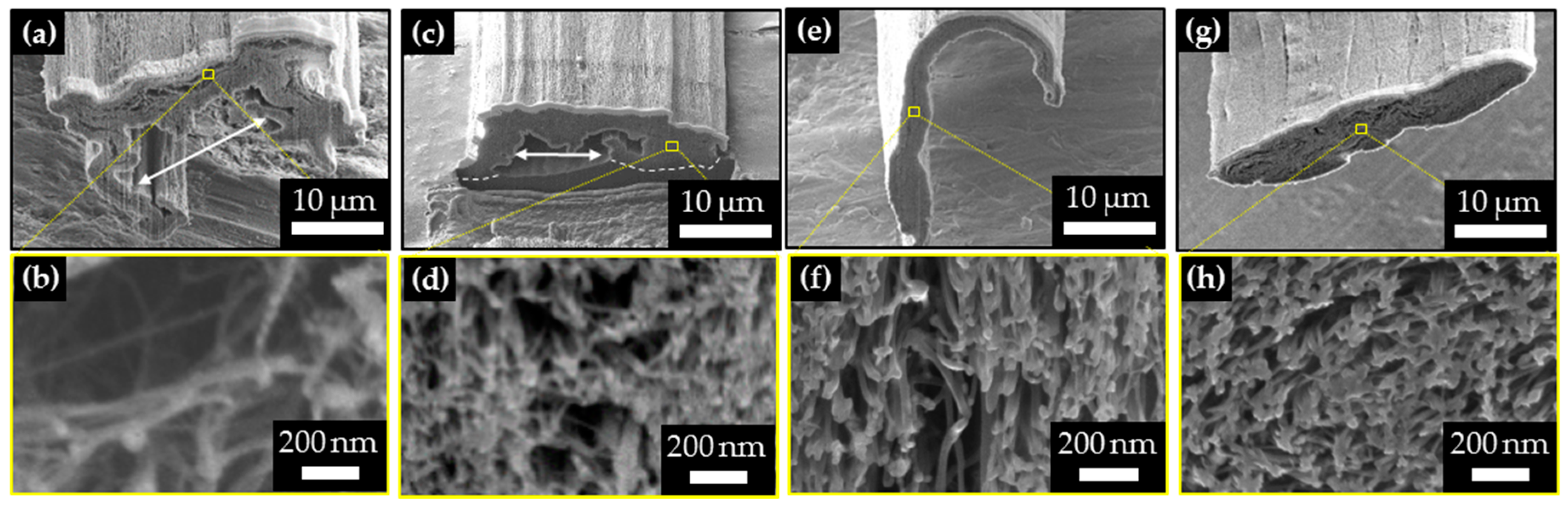
Figure 3.
(a) The schematic diagram and (b,c) TEM images of the hierarchical structure of CNTF. The effects of pressing on the distribution of the structures of CNTF: (d) bundle-to-bundle distances db of CNTF and (e) bundle diameters D.
Figure 3.
(a) The schematic diagram and (b,c) TEM images of the hierarchical structure of CNTF. The effects of pressing on the distribution of the structures of CNTF: (d) bundle-to-bundle distances db of CNTF and (e) bundle diameters D.
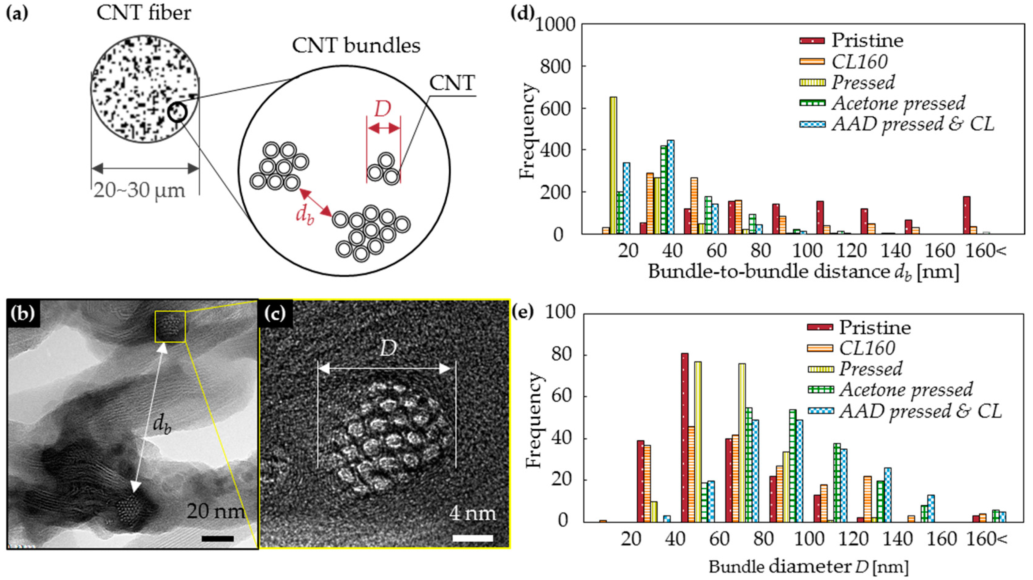
Figure 4.
The contact angle to the CNT films of liquid: (a) water, (b) acetone, and (c) azelaic acid dichloride (AAD). (d) Schematic diagram of contact angle measurements method. (e) The contact angle of liquids vs. time. Slow-motion videos available (Supporting materials).
Figure 4.
The contact angle to the CNT films of liquid: (a) water, (b) acetone, and (c) azelaic acid dichloride (AAD). (d) Schematic diagram of contact angle measurements method. (e) The contact angle of liquids vs. time. Slow-motion videos available (Supporting materials).

Figure 5.
(a) The FT-IR spectroscopy of CNTs after cross-linking reactions at various temperatures. (b) Representative Raman spectra of the pristine CNTF and CL160. XPS of (c) pristine CNTs and (d) CL160. Cross-linking reaction was successful at 160 °C.
Figure 5.
(a) The FT-IR spectroscopy of CNTs after cross-linking reactions at various temperatures. (b) Representative Raman spectra of the pristine CNTF and CL160. XPS of (c) pristine CNTs and (d) CL160. Cross-linking reaction was successful at 160 °C.
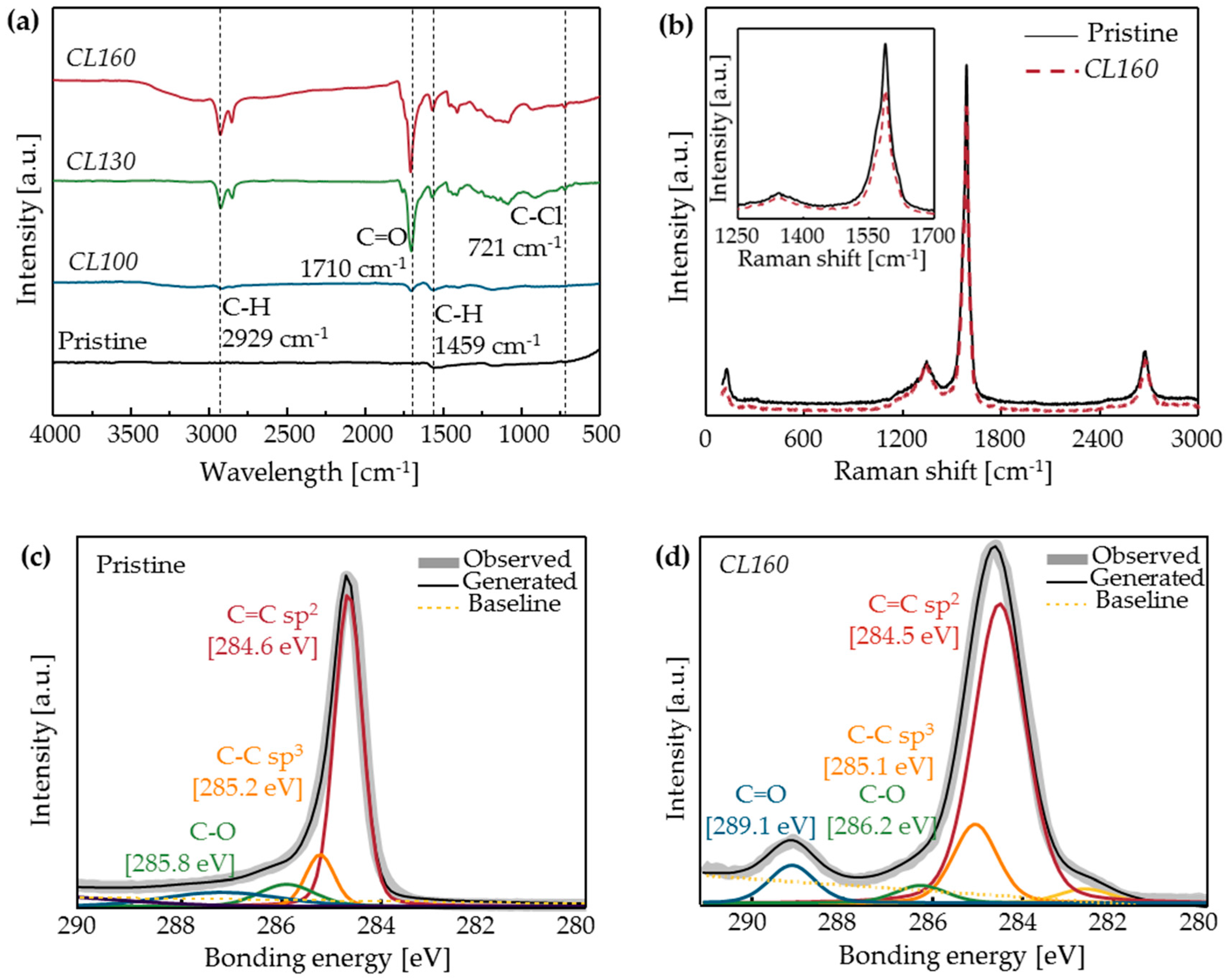
Figure 6.
(a) The specific strength (bars) and linear density (circles) Error bars: minimum to maximum; and (b) Representative stress-strain curve of CNTFs.
Figure 6.
(a) The specific strength (bars) and linear density (circles) Error bars: minimum to maximum; and (b) Representative stress-strain curve of CNTFs.

Figure 7.
The modulus-strain curves: (a) Pristine, (b) pressed, and (c) AAD pressed and CL. Maximum modulus increased after the fibers were treated.
Figure 7.
The modulus-strain curves: (a) Pristine, (b) pressed, and (c) AAD pressed and CL. Maximum modulus increased after the fibers were treated.


Table 1.
The sample name and treated methods.
| Code | Sample Name | Roller Pressing | Solvent Infiltration | Cross-Linking Reaction (Temperature) | Related Figures |
|---|---|---|---|---|---|
| 0 | Pristine | no | no | no | – |
| 1 | CL100 | no | yes (AAD) | yes (100 °C) | Figure 1b (up) |
| 1 | CL130 | no | yes (AAD) | yes (130 °C) | Figure 1b (up) |
| 1 | CL160 | no | yes (AAD) | yes (160 °C) | Figure 1b (up) |
| 2 | Pressed | yes | no | no | – |
| 3 | Acetone pressed | yes | yes (Acetone) | no | – |
| 4 | AAD pressed and CL | yes | yes (AAD) | yes (160 °C) | Figure 1a,b (down) |
Table 2.
The surface tension at 25 °C and 1 atm, and the contact angle to the CNT films of three solvents.
Table 2.
The surface tension at 25 °C and 1 atm, and the contact angle to the CNT films of three solvents.
| Liquid | Surface Tension (mN·m−1) | Contact Angle θ (°) | (mN·m−1) |
|---|---|---|---|
| Water | 72.0 | 106.7 | −20.7 |
| Acetone | 22.9 | 9.0 | 22.6 |
| AAD | 36.5 | 27.3 | 32.4 |
Table 3.
The average ± s.d. (6 ≤ n ≤ 8) mechanical properties of CNTFs.
| Factors | Unit | Sample Name | ||||
|---|---|---|---|---|---|---|
| Pristine | CL160 | Pressed | Acetone Pressed | AAD Pressed and CL | ||
| Specific strength | N/tex | 0.40 ± 0.05 | 0.36 ± 0.04 | 0.47 ± 0.01 | 0.49 ±0.03 | 0.67 ± 0.04 |
| Tensile strength | MPa | 180 ± 20 | 180 ± 10 | 680 ± 20 | 350 ± 20 | 380 ± 20 |
| Load at break | cN | 2.83 ± 0.25 | 1.94 ± 0.15 | 4.41 ± 0.16 | 2.98 ± 0.18 | 3.61 ± 0.22 |
| Linear density | tex | 0.07 ± 0.01 | 0.06 ± 0.00 | 0.07 ± 0.01 | 0.06 ± 0.00 | 0.05 ± 0.00 |
| Cross-sectional area | μm2 | 160 | 110 | 66 | 85 | 96 |
| Strain at break | % | 3.4 ± 0.6 | 3.6 ± 0.6 | 4.3 ± 0.2 | 3.7 ± 0.4 | 3.5 ± 0.4 |
| Toughness | N/tex | 0.74 ± 0.05 | 0.90 ± 0.29 | 1.43 ± 0.09 | 1.31 ± 0.20 | 1.36 ± 0.22 |
| Maximum tangent modulus | N/tex | 0.26 ± 0.01 | 0.25 ± 0.02 | 0.32 ±0.02 | 0.31 ± 0.02 | 0.37 ± 0.03 |
© 2018 by the authors. Licensee MDPI, Basel, Switzerland. This article is an open access article distributed under the terms and conditions of the Creative Commons Attribution (CC BY) license (http://creativecommons.org/licenses/by/4.0/).
Share and Cite
MDPI and ACS Style
Cho, H.; Lee, J.; Lee, H.; Lee, S.-H.; Park, J.; Lee, C.-H.; Lee, K.-H. Effects of Wet-Pressing and Cross-Linking on the Tensile Properties of Carbon Nanotube Fibers. Materials 2018, 11, 2170. https://doi.org/10.3390/ma11112170
AMA Style
Cho H, Lee J, Lee H, Lee S-H, Park J, Lee C-H, Lee K-H. Effects of Wet-Pressing and Cross-Linking on the Tensile Properties of Carbon Nanotube Fibers. Materials. 2018; 11(11):2170. https://doi.org/10.3390/ma11112170
Chicago/Turabian StyleCho, Hyunjung, Jinwoo Lee, Haemin Lee, Sung-Hyun Lee, Junbeom Park, Cheol-Hun Lee, and Kun-Hong Lee. 2018. "Effects of Wet-Pressing and Cross-Linking on the Tensile Properties of Carbon Nanotube Fibers" Materials 11, no. 11: 2170. https://doi.org/10.3390/ma11112170
Note that from the first issue of 2016, this journal uses article numbers instead of page numbers. See further details here.