Strengthening of Existing Bridge Structures for Shear and Bending with Carbon Textile-Reinforced Mortar


Abstract
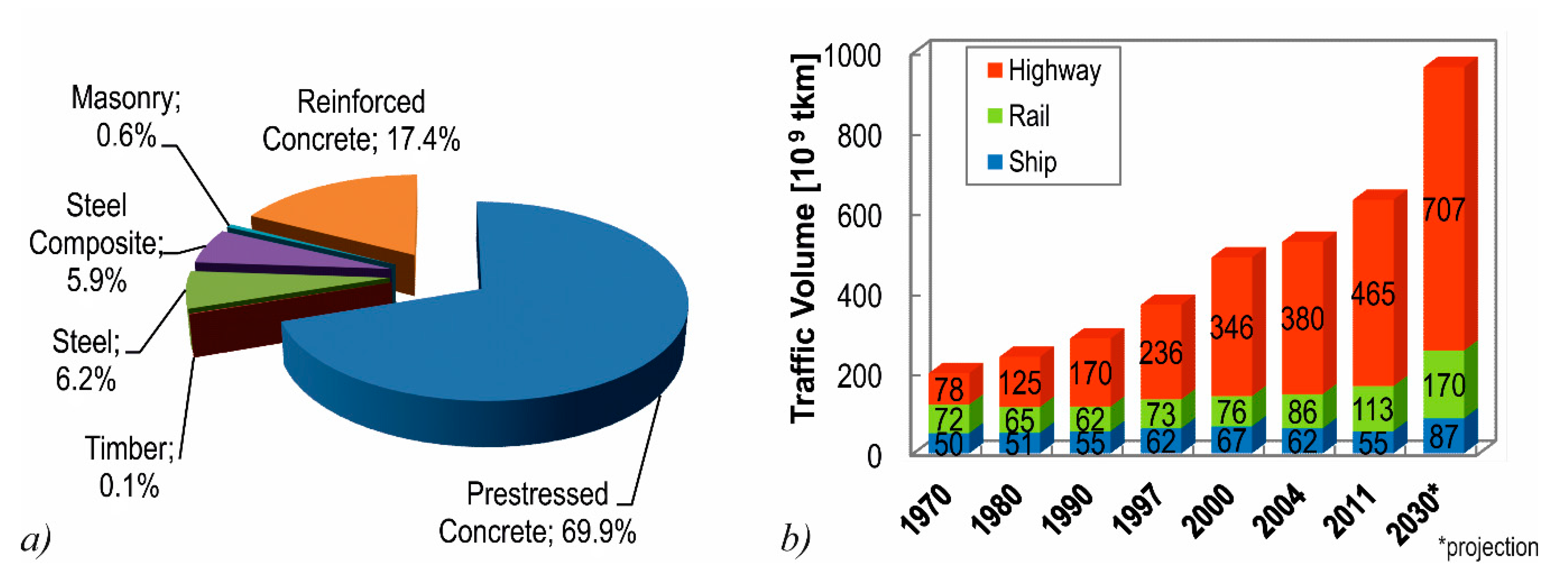
:1. Introduction
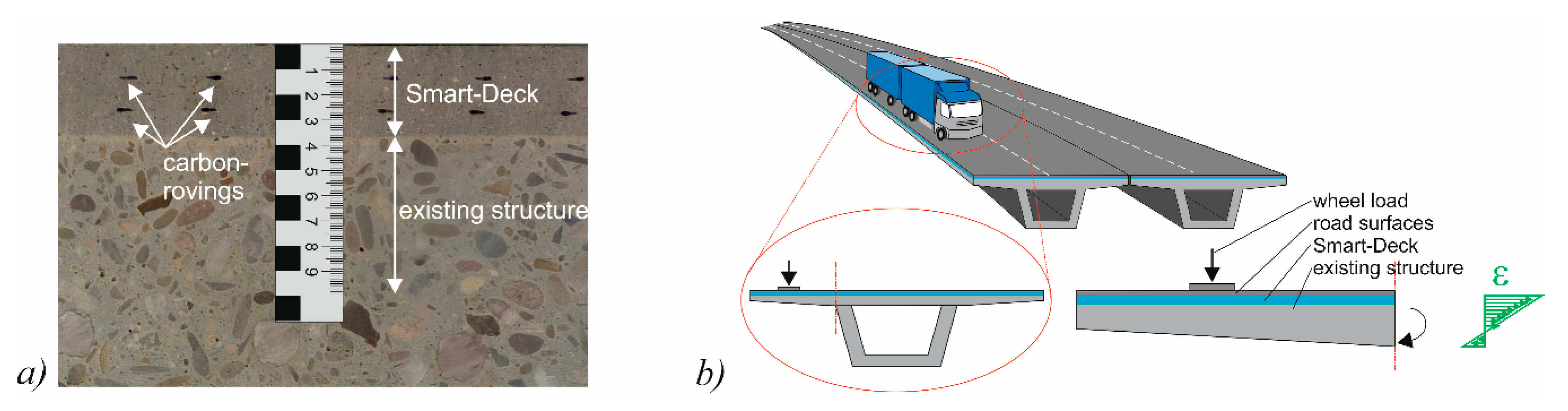
2. CTRM Layer for Bridge Deck Slabs
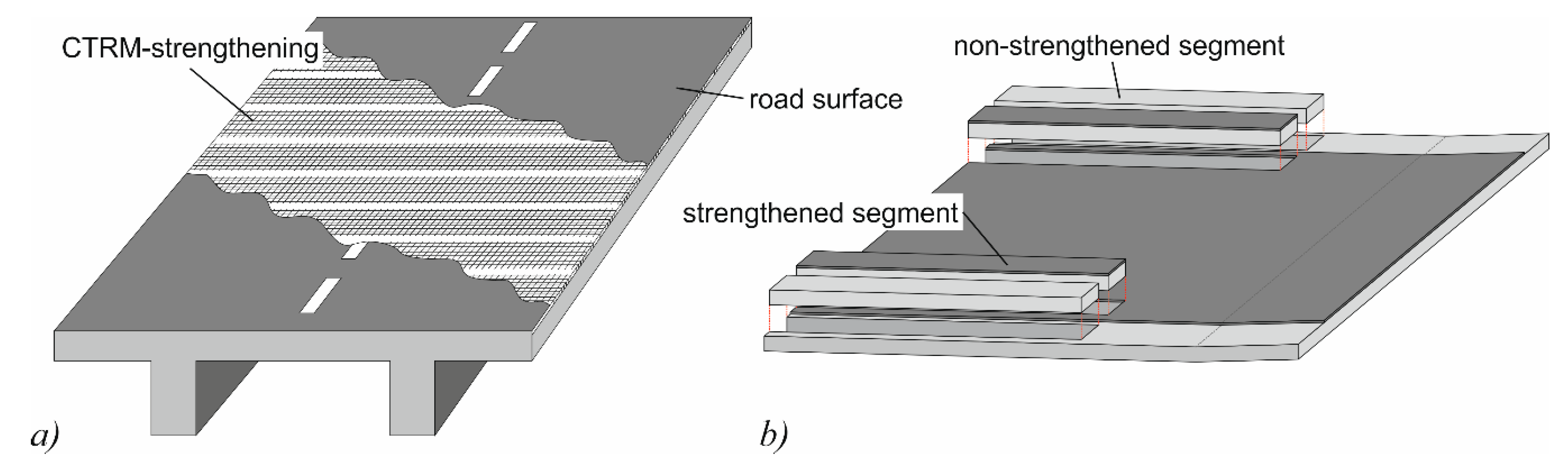
2.1. Concept
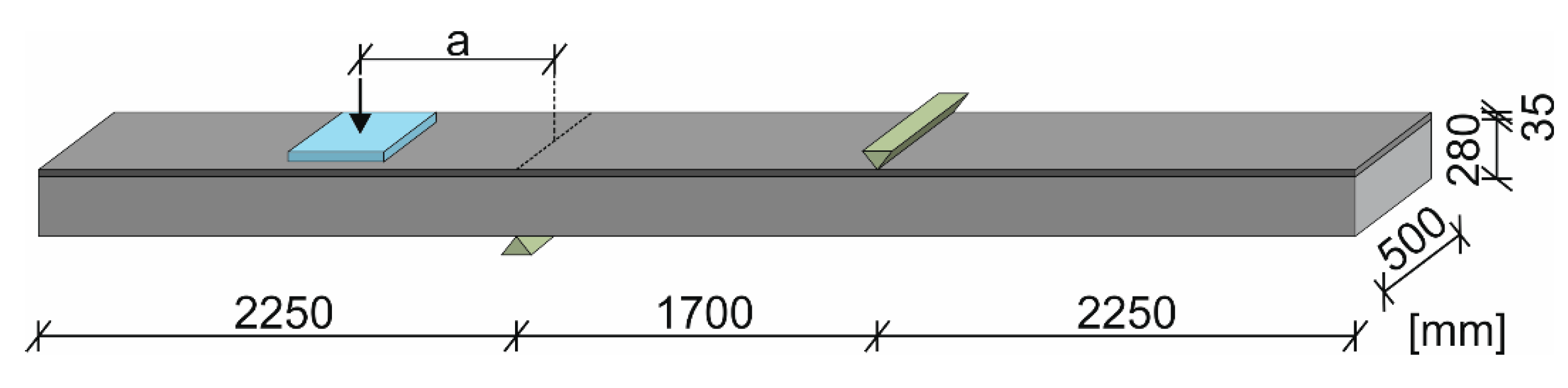
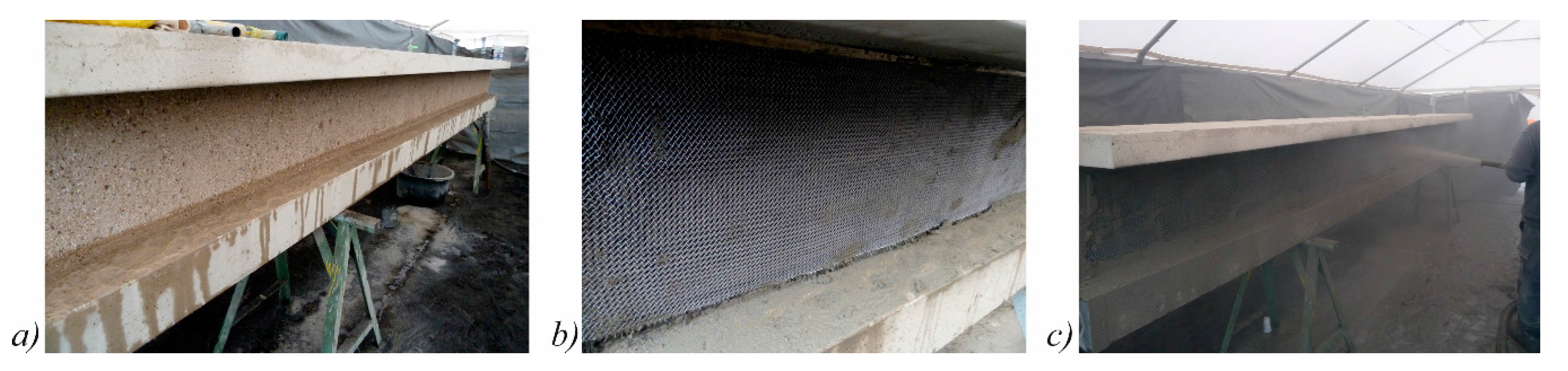
2.2. Preparation of the Test Specimens
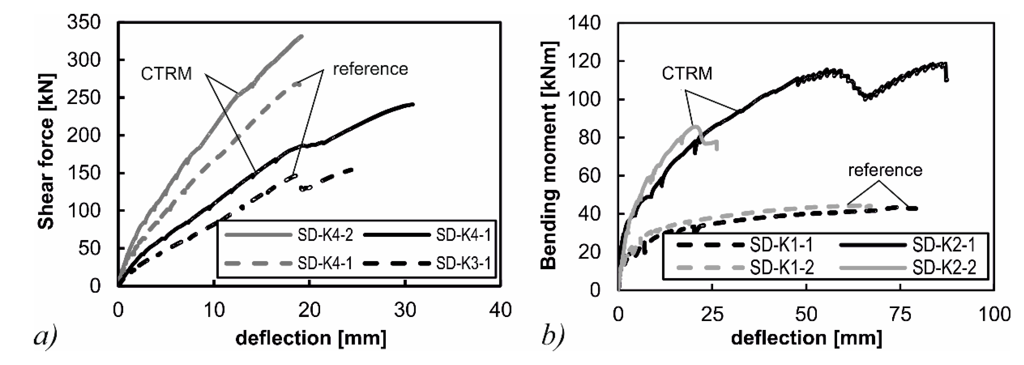
2.3. Investigation of the Strengthening Effect
3. Strengthening of Webs with a CTRM layer
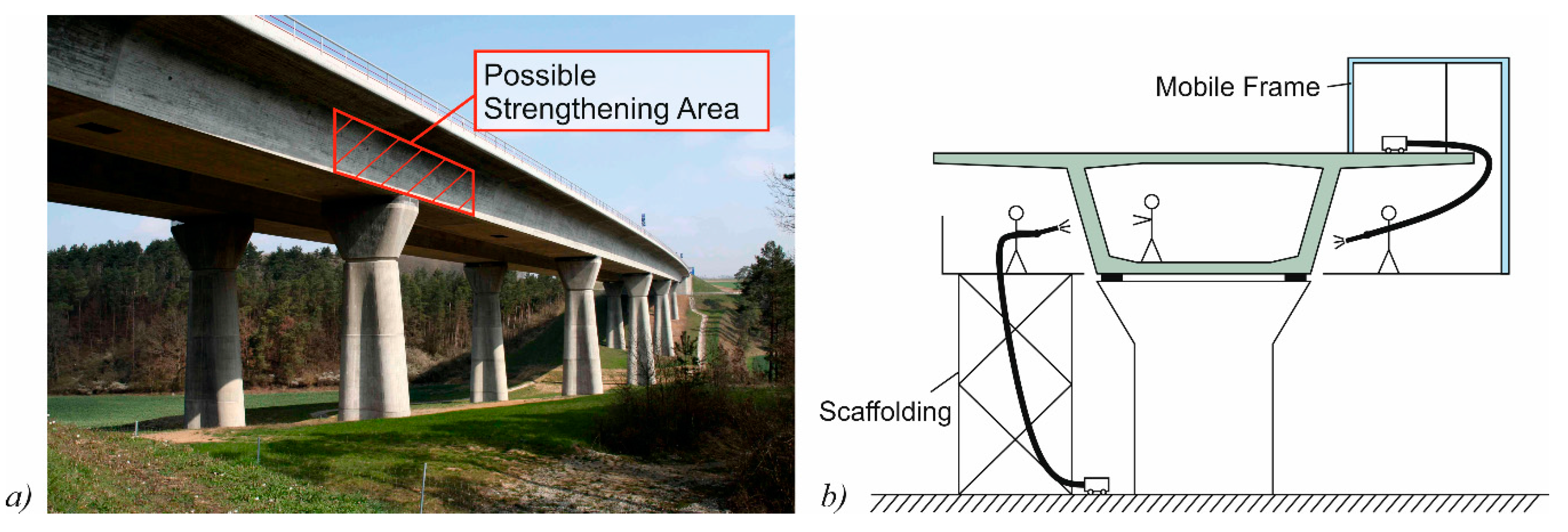
3.1. Concept and Preliminary Investigations
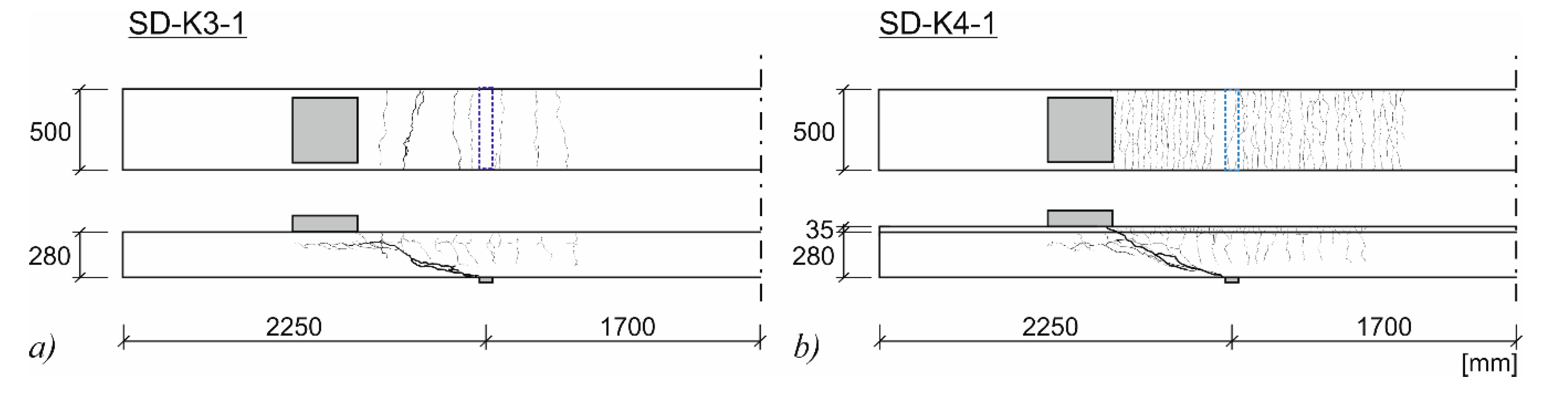
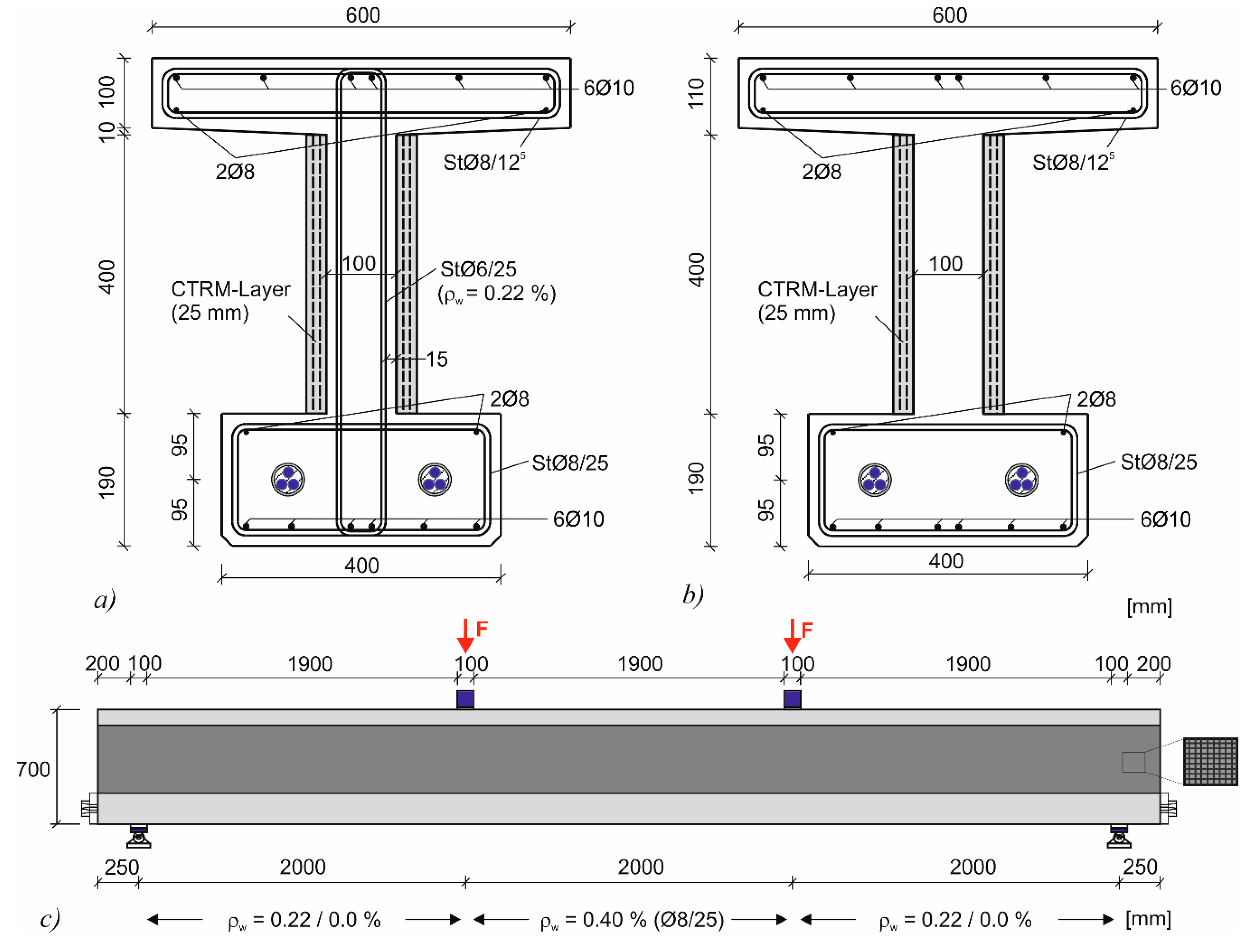
3.2. Test Specimens and Test Setup
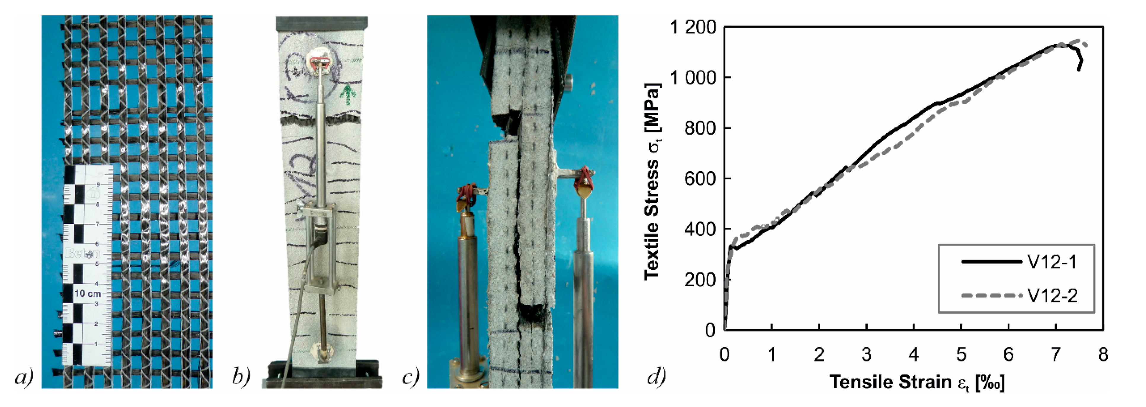
3.3. Material Properties
3.4. Test Specimens and Test Setup
3.5. Test Results
3.5.1. Load Regime
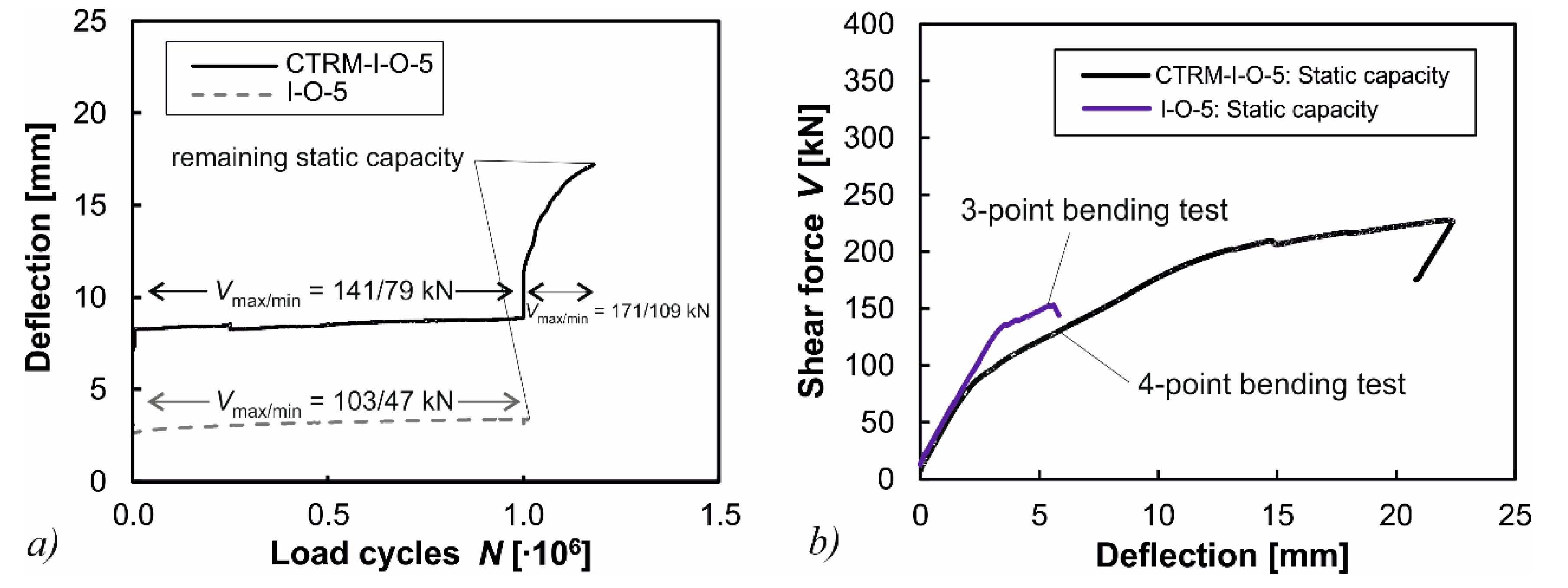
3.5.2. Specimen CTRM-I-O-5
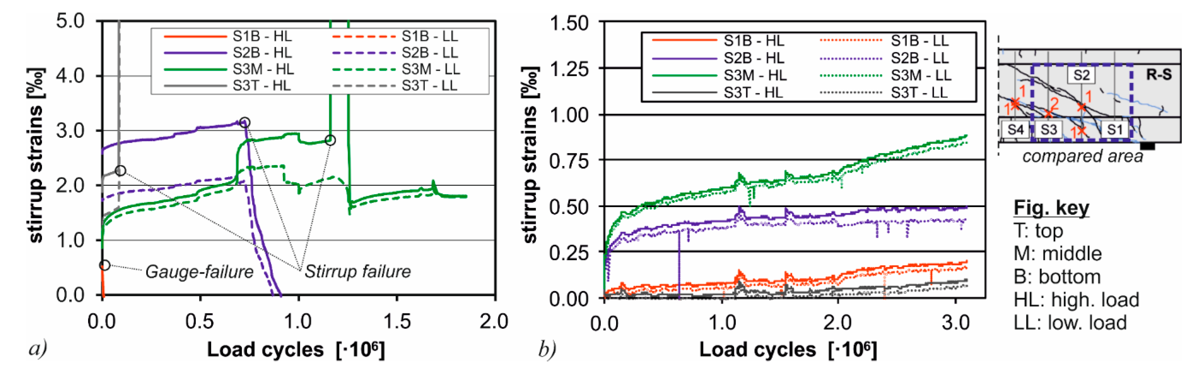
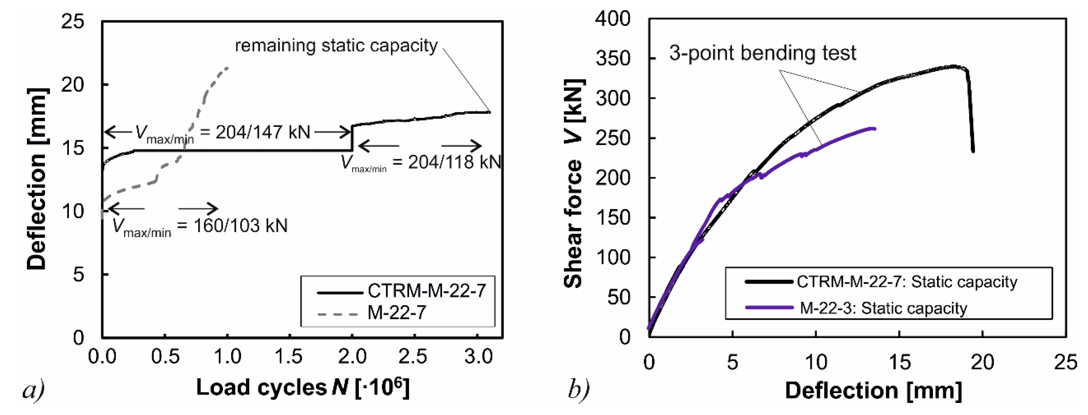
3.5.3. Specimen CTRM-M-22-7
3.5.4. Summary
- Although the strengthening layer was not anchored in the compression or tension chord, a significant strengthening effect was observed. This effect can be explained by the contribution of the horizontal rovings which are activated at crack opening.
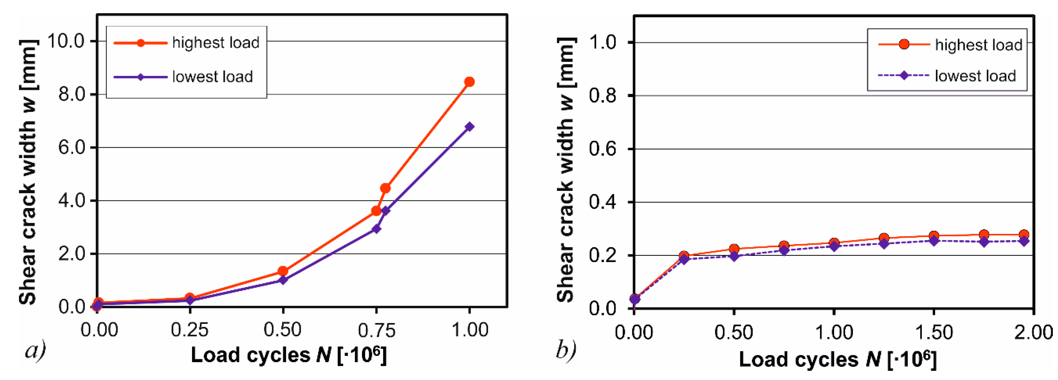
- For the specimen without shear reinforcement, additional 180,000 load cycles could be sustained after shear crack formation which results in a much more ductile behavior in comparison to non-strengthened specimens.
- For the specimen with shear reinforcement a significant reduction of stirrup strains was observed, as well as significantly smaller shear crack widths. By this, a progressive fatigue failure was prevented by the CTRM-strengthening.
- A bond failure between old concrete and strengthening layer could not be observed in any of the tests as the surface was sufficiently roughened and cleaned prior to strengthening. However, if the surface is not prepared according to the applicable standards [49], bond failure might occur, neutralizing a potential strengthening effect.
4. Conclusions
Acknowledgments
Author Contributions
Conflicts of Interest
References
- BMVI. Strategie zur Ertuechtigung der Strassenbruecken im Bestand der Bundesfernstrassen; German Federal Ministry of Transport and Digital Infrastructure: Berlin, Germany, 22 May 2013.
- Naumann, J. Bridges and heavy goods traffic—An inventory. Bauingenieur 2010, 85, 1–9. [Google Scholar]
- Freundt, U.; Böning, S.; Kaschner, R. Road bridges between actual and future heavy load traffic-Road traffic loads according to DIN EN 1991-2/NA. Beton Stahlbetonbau 2011, 106, 736–746. [Google Scholar] [CrossRef]
- Ickert, L.; Matthes, U.; Rommerskirchen, S.; Weyand, E.; Schlesinger, M.; Limbers, J. Abschaetzung der langfristigen Entwicklung des Gueterverkehrs in Deutschland bis 2050; Project for the BMVI, Report: 26.0185/2006; BMVI: Basel, Switzerland, 31 May 2007. [Google Scholar]
- Naumann, J. Bridges and heavy goods vehicle traffic—A strategy for strengthening existing bridges on federal trunk roads. Bauingenieur 2010, 85, 210–216. [Google Scholar]
- Curbach, M.; Garibaldi, M.P.; Steinbock, O. Dealing with the bridge inventory—A comparison between Germany and the USA. Bauingenieur 2016, 91, 215–226. [Google Scholar]
- Chen, W.; Xie, Z.; Yan, B. Research on the general method for extrapolating traffic load effects for highway bridges. Stahlbau 2014, 83, 186–198. [Google Scholar] [CrossRef]
- Lantsoght, E.O.L.; van der Veen, C.; Walraven, J.C.; de Boer, A. Recommendations for the shear assessment of reinforced concrete slab bridges from experiments. Struct. Eng. Int. 2013, 23, 418–426. [Google Scholar] [CrossRef]
- Schellenberg, K.; Vogel, T.; Chèvre, M.; Alvarez, M. Assessment of bridges on the Swiss national roads. Struct. Eng. Int. 2013, 4, 402–410. [Google Scholar] [CrossRef]
- Fischer, O.; Müller, A.; Lechner, T.; Wild, M.; Kessner, K. Findings and insights concerning the results of re-analyzed concrete bridges in Germany. Beton Stahlbetonbau 2014, 109, 107–127. [Google Scholar] [CrossRef]
- Hegger, J.; Herbrand, M.; Stark, A.; Classen, M. The future of structural concrete: Light, filigree and sustainable. Bauingenieur 2015, 90, 337–344. [Google Scholar]
- Teworte, F.; Herbrand, M. Structural shear assessment of an existing concrete bridge under static and fatigue loading. Bauingenieur 2014, 89, 531–536. [Google Scholar]
- Hegger, J.; Marzahn, G.; Teworte, F.; Herbrand, M. Principal tensile stress criterion for the shear assessment of existing concrete bridges. Beton Stahlbetonbau 2015, 110, 82–95. [Google Scholar] [CrossRef]
- Herbrand, M.; Classen, M. Shear tests on continuous pre-stressed concrete beams with external prestressing. Struct. Concr. 2015, 16, 428–437. [Google Scholar] [CrossRef]
- Teworte, F.; Herbrand, M.; Hegger, J. Structural assessment of concrete bridges in Germany-Shear resistance under static and fatigue loading. Struct. Eng. Int. 2015, 25, 266–274. [Google Scholar] [CrossRef]
- Hegger, J.; Maurer, R.; Zilch, K.; Herbrand, M.; Kolodzieiczyk, A.; Dunkelberg, D. Assessment of the shear capacity of existing prestressed concrete bridge girders. Bauingenieur 2014, 89, 500–509. [Google Scholar]
- Herbrand, M. Shear Strength Models for Reinforced and Prestressed Concrete Members. Ph.D. Thesis, RWTH Aachen University, Aachen, Germany, 9 June 2017. [Google Scholar]
- Herbrand, M.; Kueres, D.; Classen, M.; Hegger, J. Uniform shear design method for existing reinforced and prestressed concrete bridges. Beton Stahlbetonbau 2016, 111, 58–67. [Google Scholar] [CrossRef]
- Herbrand, M.; Classen, M.; Stark, A.; Kueres, D. Uniform shear design method for existing reinforced and pre-stressed concrete bridges–extended background. Bauingenieur 2016, 91, 487–495. [Google Scholar]
- Welsch, T.; Reissen, K.; Schnellenbach-Held, M.; Hegger, J.; von Weschpfennig, D.; Haardt, P. Experiences on the strengthening of concrete bridges. Beton Stahlbetonbau 2016, 111, 241–252. [Google Scholar] [CrossRef]
- Haveresch, K.H. Checking and strengthening older pre-stressed concrete bridges. Beton Stahlbetonbau 2011, 106, 89–102. [Google Scholar] [CrossRef]
- Herbrand, M.; Hegger, J. Experimental investigations on the influence of an external prestressing on the shear capacity of pre-stressed continuous beams. Bauingenieur 2013, 88, 509–517. [Google Scholar]
- Hegger, J.; Voss, S. Investigation of the load-bearing behavior and potential of textile-reinforced concrete. Eng. Struct. 2008, 30, 2050–2056. [Google Scholar] [CrossRef]
- Hegger, J.; Horstmann, M.; Voss, S.; Will, N. Textile-reinforced concrete load-bearing behaviour, design and application. Beton Stahlbetonbau 2007, 102, 362–370. [Google Scholar] [CrossRef]
- Hegger, J.; Will, N.; Bruckermann, O.; Voss, S. Load-bearing behaviour and simulation of textile-reinforced concrete. Mater. Struct. 2006, 39, 765–776. [Google Scholar] [CrossRef]
- Shams, A.; Hegger, J.; Horstmann, M. An analytical model for sandwich panels made of textile-reinforced concrete. Constr. Build. Mater. 2014, 64, 451–459. [Google Scholar] [CrossRef]
- Kulas, C.; Rempel, S. Bending bearing behavior of impregnated textile reinforcement for concrete elements. Bauingenieur 2015, 90, 248–251. [Google Scholar]
- Tietze, M.; Kahnt, A.; Schladitz, F.; Scheerer, S.; Curbach, M. C3—Carbon reinforced concrete construction of the future. In Proceedings of the fib Symposium, Copenhagen, Denmark, 18 May 2015. [Google Scholar]
- Hegger, J.; Kulas, C.; Raupach, M.; Büttner, T. Load-Bearing behavior and durability of a slender textile-reinforced concrete bridge. Beton Stahlbetonbau 2011, 106, 72–80. [Google Scholar] [CrossRef]
- Scholzen, A.; Chudoba, R.; Hegger, J. Thin-walled shell structure made of textile-reinforced concrete: Design, dimensioning and realization. Beton Stahlbetonbau 2012, 107, 767–775. [Google Scholar] [CrossRef]
- Kromoser, B.; Ritt, M. Optimized shapes for textile-reinforced concrete structures. Bauingenieur 2016, 91, 425–433. [Google Scholar]
- Horstmann, M.; Hegger, J. Sandwich facades made of textile-reinforced concrete-experimental investigations. Bautechnik 2011, 88, 281–291. [Google Scholar] [CrossRef]
- Scholzen, A.; Chudoba, R.; Hegger, J. Thin-walled shell structures made of textile-reinforced concrete, Part I: Structural design and construction. Struct. Concr. 2015, 16, 106–114. [Google Scholar] [CrossRef]
- Scholzen, A.; Chudoba, R.; Hegger, J. Thin-walled shell structures made of textile-reinforced concrete, Part II: Experimental characterization, ultimate limit state assessment and numerical simulation. Struct. Concr. 2015, 16, 115–124. [Google Scholar] [CrossRef]
- Rempel, S.; Will, N.; Hegger, J.; Beul, P. Filigree textile-reinforced concrete constructions performance and potential application of innovative composite material. Beton Stahlbetonbau 2015, 110, 83–93. [Google Scholar] [CrossRef]
- Brückner, A.; Ortlepp, R.; Curbach, M. Textile-reinforced concrete for strengthening in bending and shear. Mater. Struct. 2006, 39, 741–748. [Google Scholar] [CrossRef]
- Brückner, A.; Ortlepp, R.; Curbach, M. Anchoring of shear strengthening for T-beams made of TRC. Mater. Struct. 2008, 41, 407–418. [Google Scholar] [CrossRef]
- Barhum, R.; Büllesbach, J.; Müller, A. Textile-reinforced concrete for repair of a balcony panels made of reinforced concrete. Bauingenieur 2015, 90, 241–247. [Google Scholar]
- Erhard, E.; Weiland, S.; Lorenz, E.; Schladitz, F.; Beckmann, B.; Curbach, M. Applications of textile-reinforced concrete strengthening. Beton Stahlbetonbau 2015, 110, 74–82. [Google Scholar] [CrossRef]
- Herbrand, M.; Classen, M.; Hegger, J. Shear tests on pre-stressed concrete beams strengthened with carbon textile-reinforced spray mortar under cyclic loading. Beton Stahlbetonbau 2016, 109, 576–587. [Google Scholar] [CrossRef]
- Herbrand, M.; Adam, V.; Hegger, J. Investigations on the strengthening of existing highway bridges under shear and flexural loading with textile-reinforced Mortar. In Proceedings of the fib Symposium, Maastricht, The Netherlands, 14 June 2017. [Google Scholar]
- Brückner, A.; Wellner, S.; Ortlepp, R.; Scheerer, S.; Curbach, M. T-beams strengthened with TRC under non predominantly static loading. Beton Stahlbetonbau 2013, 108, 169–178. [Google Scholar] [CrossRef]
- Solidian GmbH. Available online: https://www.solidian.com/en/ (accessed on 11 September 2017).
- Eurocode 1: Actions on Structures–Part 2: Traffic Loads on Bridges; EN 1991-2; CEN European Committee for Standardisation: Brussels, Belgium, 2010.
- Fisker, J.; Hagsten, L.G. Mechanical model for the shear capacity of R/C beams without stirrups: A proposal based on limit analysis. Eng. Struct. 2016, 115, 220–231. [Google Scholar] [CrossRef]
- Lorenz, E.; Schütze, E.; Schladitz, F.; Curbach, M. Textile-reinforced concrete–Overview of standard test methods. Beton Stahlbetonbau 2013, 108, 711–722. [Google Scholar] [CrossRef]
- Teworte, F.; Hegger, J. Fatigue of prestressed beams without web reinforcement under cyclic shear. Beton Stahlbetonbau 2013, 108, 34–46. [Google Scholar] [CrossRef]
- Teworte, F.; Hegger, J. Fatigue of prestressed beams with web reinforcement under cyclic shear. Beton Stahlbetonbau 2013, 108, 475–486. [Google Scholar] [CrossRef]
- Momber, A.W.; Schulz, R.R. Handbuch der Oberflächenbearbeitung Beton; Birkhäuser Verlag: Basel, Switzerland, 2006; ISBN 978-3-7643-6218-8. [Google Scholar]
- Hegger, J.; Sherif, A.; Görtz, S. Investigation of pre- and postcracking shear behavior of pre-stressed concrete beams using innovative measuring techniques. ACI Struct. J. 2004, 101, 183–192. [Google Scholar]
- Herbrand, M.; Classen, M.; Adam, V. Shear tests on pre-stressed concrete continuous beams with rectangular and I-shaped cross-sections. Bauingenieur 2017, 92. [Google Scholar] [CrossRef]
- Aramis, version 5.4; User Information Manual; GOM GmbH: Braunschweig, Germany, 2005.


| Specimen | CTRM (mm²/m) | Rebar (cm²/m) | ds (m) | a (m) |
|---|---|---|---|---|
| SD-K1-1 | 0 | 5.24 | 0.21 | 1.3 |
| SD-K1-2 | 0 | 5.24 | 0.21 | 1.0 |
| SD-K2-1 | 280 | 5.24 | 0.215 | 1.3 |
| SD-K2-2 | 280 | 5.24 | 0.205 | 1.0 |
| SD-K3-1 | 0 | 25.13 | 0.215 | 1.0 |
| SD-K3-2 | 0 | 25.13 | 0.205 | 0.7 |
| SD-K4-1 | 280 | 25.13 | 0.235 | 1.0 |
| SD-K4-2 | 280 | 25.13 | 0.22 | 0.7 |
| Specimen | CTRM (mm²/m) | wmax (mm) | Mmax (kNm) | Vmax (Kn) | η (%) |
|---|---|---|---|---|---|
| SD-K1-1 | 0 | 89 | 43.4 | - | - |
| SD-K1-2 | 0 | 71 | 44.9 | - | - |
| SD-K2-1 | 280 | 73 | 118.7 | - | 174 |
| SD-K2-2 | 280 | 22 | 85.7 | - | 91 |
| SD-K3-1 | 0 | 26 | - | 154 | - |
| SD-K3-2 | 0 | 32 | - | 268.5 | - |
| SD-K4-1 | 280 | 24 | - | 240.9 | 56 |
| SD-K4-2 | 280 | 22 | - | 331.5 | 23 |
| Textile | Shotcrete; dag = 4 mm | SPCC; dag = 2 mm |
|---|---|---|
| carbon fiber + epoxy resin | 2397 MPa | 2928 MPa |
| AR-glass fiber + epoxy resin | 1640 MPa | 2076 MPa |
| carbon + styrol-butadien (type 1) | 935 MPa | 1198 MPa |
| carbon + styrol-butadien (type 2) | 362 MPa | 276 MPa |
| unimpregnated carbon | - | 1136 MPa |
| Specimen | Concrete | Shot Mortar (SPCC) | |||||
|---|---|---|---|---|---|---|---|
| fcm,cyl (MPa) | fcm,cube (MPa) | fct,ax (MPa) | fct,split (MPa) | Ecm (MPa) | fcm,prism (MPa) | fct,flex (MPa) | |
| I-O-5 | 29.4 (6) | 34.9 (10) | 2.80 (10) | 2.54 (3) | 22,200 (6) | - | - |
| CTRM-I-O-5 | 42.3 (6) | 47.0 (6) | 2.98 (13) | 3.44 (6) | 26,790 (6) | 53.8 (10) | 6.30 (5) |
| M-22-3 | 35.3 (6) | 38.6 (9) | 2.68 (15) | 2.43 (4) | 24,833 (6) | - | - |
| M-22-7 | 32.0 (7) | 35.4 (9) | 2.55 (15) | 2.59 (5) | 23,900 (7) | - | - |
| CTRM-M-22-7 | 43.0 (6) | 47.2 (4) | 3.10 (14) | 3.25 (6) | 25,140 (6) | 44.6 (8) | 7.12 (4) |
| Specimen | fy;0,2 (MPa) | ft (MPa) | Es (MPa) |
|---|---|---|---|
| M-22-3 | 587 | 626 | 200,777 |
| M-22-7 | 587 | 626 | 200,777 |
| CTRM-M-22-7 | 595 | 633 | 203,800 |
| Specimen | Pmt (kN) | σcp,mt (MPa) | fp0,2 (MPa) | fpt (MPa) | Ep (MPa) |
|---|---|---|---|---|---|
| I-O-5 | 320 | 1.78 | 1764 | 1950 | 190,000 |
| CTRM-I-O-5 | 327 | 1.82 | 1764 | 1950 | 190,000 |
| M-22-3 | 320 | 1.78 | 1764 | 1950 | 190,000 |
| M-22-7 | 314 | 1.75 | 1764 | 1950 | 190,000 |
| CTRM-M-22-7 | 329 | 1.83 | 1764 | 1950 | 190,000 |
| Specimen | Vcrack (kN) | Load Cycles × 10³ | Vmax (kN) | Vmin (kN) | ΔV (kN) | |
|---|---|---|---|---|---|---|
| Ni | ΣNi | |||||
| I-O-5 | 176 | 1000 | 1000 | 103 | 47 | 56 |
| 1011 | 2011 | 102 | 35 | 67 | ||
| CTRM-I-O-5 | 188 | 1000 | 1000 | 141 | 79 | 62 |
| 180 | 1180 | 171 | 109 | 62 | ||
| M-22-7 | 145 | 1853 | 1853 | 160 | 103 | 57 |
| CTRM-M-22-7 | 185 | 2000 | 2000 | 204 | 147 | 60 |
| 1100 | 3100 | 204 | 118 | 86 | ||
© 2017 by the authors. Licensee MDPI, Basel, Switzerland. This article is an open access article distributed under the terms and conditions of the Creative Commons Attribution (CC BY) license (http://creativecommons.org/licenses/by/4.0/).
Share and Cite
Herbrand, M.; Adam, V.; Classen, M.; Kueres, D.; Hegger, J. Strengthening of Existing Bridge Structures for Shear and Bending with Carbon Textile-Reinforced Mortar. Materials 2017, 10, 1099. https://doi.org/10.3390/ma10091099
Herbrand M, Adam V, Classen M, Kueres D, Hegger J. Strengthening of Existing Bridge Structures for Shear and Bending with Carbon Textile-Reinforced Mortar. Materials. 2017; 10(9):1099. https://doi.org/10.3390/ma10091099
Chicago/Turabian StyleHerbrand, Martin, Viviane Adam, Martin Classen, Dominik Kueres, and Josef Hegger. 2017. "Strengthening of Existing Bridge Structures for Shear and Bending with Carbon Textile-Reinforced Mortar" Materials 10, no. 9: 1099. https://doi.org/10.3390/ma10091099