1. Introduction
Photovoltaic thermal (PVT) systems utilize heat which is exhausted from building integrated photovoltaic (BIPV) modules, occurring together with electricity generation, for domestic hot water and space heating. In other words, electrical efficiency is enhanced through BIPV arrays, and the resulting waste heat is reused as a source of energy for buildings. Air-type PVT systems can use fans to introduce air heated in the air channel at the back side of photovoltaic (PV) modules into buildings, to be used as a source of energy for heating purposes. The PV efficiency is enhanced by releasing the heated air, and building envelopes integrated with PVT collectors contribute to reducing the cooling load even in the summer by the cooling of the envelope. By generating both thermal and electrical energy at the same time, PVT systems can improve the utilization of solar energy while enhancing the energy performance of buildings. Air-type PVT systems, which use air as the heat transfer medium, offer several advantages. First, they are less susceptible to leakage and corrosion and are less likely to freeze compared to liquid-based solar thermal collectors, which require water or antifreeze. Because air has a lower specific heat value than water, it is inefficient to apply these types of collectors directly for heating applications and domestic hot water production. In order to ensure the efficient integration of air-type PVT systems into existing buildings, their system designs and operations must be carefully considered. Air-type PVT systems must be properly integrated into existing facilities to support the maximum utilization of air acquired from collectors. Given that air is used as the heat-transfer medium, the heated air can be directly used in buildings without storage or without passing through a heat exchanger. The easiest and most efficient means of using heated air from PVT collectors is to use it as a source of energy for space heating.
A considerable amount of research has been conducted regarding the performance of air-type PVT collectors and systems. One study focusing on such collectors [
1] involved various designs of PVT air collectors (e.g., air channel above PV, air channel below PV, PV in a single-pass design and PV in a double-pass design); these were designed and their overall electrical and thermal performances were evaluated through numerical modeling. In another study [
2], various types of PVT air collectors were suggested to improve performance levels. These included the use of a single cover, the absence of a glass cover, the attachment of metal fins and the incorporation of a metal sheet. In addition, researchers have proposed improved models of PVT air collectors that incorporate a corrugated sheet, a wire mesh (RIB) and metal air tubes [
3]. Solanki et al. reported the design, fabrication and performance assessment of a PVT air collector [
4]. Sopian et al. compared the performances under normal conditions of single and double-pass PVT air collectors [
5]. They concluded that the double-pass type of PVT air collector outperformed other types during the cooling of a solar cell. A study of PVT air collectors with numerical calculations was published by Garg and Adhikari [
6], dealing with the modeling and simulation of a PVT air collector. They described the algorithm of a simulation model for making quantitative predictions regarding the performance of the system. In other studies, numerical models of a PVT air collector were presented in order to assess the effect of factors such as the air flow, air channel depth and length, and the use of an absorber plate [
7,
8].
Other studies evaluated the efficiency of PVT air collectors depending on the utilization conditions and links to facilities [
9,
10,
11,
12]. Crawford et al. compared the energy payback time (EPBT) of a conventional BIPV system with BIPV systems incorporating heat recovery units [
13]. They reported that with the integration of a heat recovery unit, the EPBT can be reduced by nearly half. Chow et al. [
14] investigated the building integrated photovoltaic thermal air (BIPVT/a) options of a hotel building for which a PVT Façade was attached to a 24-h air-conditioned services room. The effectiveness of PV cooling by means of the natural flow of air behind the PV was investigated with two options: free openings at all sides of an air gap, and an enclosed air gap that served as a solar chimney to preheat the air.
In a study which focused on an air-type PVT system, Aste et al. designed a roof-integrated air-type PVT system in which theoretical and experimental performances were evaluated. In their study, the thermal and electrical efficiency levels of the PVT system were confirmed to be 20%–40% and 9%–10%, respectively [
15]. In another study conducted by Crawford et al., BIPVs with heat recovery units were designed and the EPBT (Energy payback time) values were analyzed. This study found that the EPBT of BIPV (a C-Si PV cell) without and with a heat recovery unit ranged from 12 to 16.5 years and from 6 to 14 years, respectively [
16]. One study used TRNSYS (Version 16.00.038) to compare the performance of an air-source heat pump (ASHP) to that of an ASHP coupled with a building integrated photovoltaic thermal (BIPVT) collector [
17]. The study found that the coefficient of performance (COP) improved when the outdoor temperature was between −3 and 10 °C (Hailu et al.). Kamel et al. [
18] integrated BIPVT collectors with an ASHP and thermal energy storage (TES), storing heat from collectors in the TES unit and using it as a source of energy for the ASHP. This led to an improved COP and a 20% decrease in the electric energy consumed. Another study integrated air-type PVT collectors on building roofs, with the design of a HVAC-supporting model created by coupling the collectors with phase change material (PCM) thermal storage [
19]. During the heating period, the air released from the back of the BIPVT collectors was used directly for heating or in the PCM thermal storage unit. During the non-heating period, a fan was used to release the heat outside of the system so as to prevent overheating and maintain good electrical efficiency. Another study designed a theoretical model of an air-type PVT collector and PCM and predicted the heat transfer rate and heat loss of the relevant systems [
20]. Lin et al. [
21] employed the TRNSYS program to analyze existing PCM and PVT-integrated PCMs, with a focus on indoor thermal comfort.
Experimental studies were also conducted in an effort to utilize heat from PVT collectors for greenhouses and for the drying of crops [
22,
23]. A solar dryer was proposed to dry grains and fruits using heat collected by PVT collectors. Direct sunlight was blocked, and the heat generated from the back was used to dry the grains and fruits. Moreover, overheating was addressed through a fan installed at the back of the dryer. A PVT-based solar greenhouse was designed and a one-year empirical study was conducted from June 2006 to May 2007. Barnwal et al. [
24] analyzed the power needed to operate a fan and determined the convective heat transfer coefficient. Another study proposed a system of air-type PVT collectors coupled with compression refrigerators [
25]. The heated air from the air-type PVT collectors was combined with heat released from condensers, and the air (a gaseous refrigerant) was dehumidified to achieve a high temperature. This led to 18% decrease in the amount of energy used by the air conditioners. Beccali et al. developed a desiccant cooling system based on air-type PVT collectors, finding a decrease in primary energy use due to the PVT collectors [
26].
Ventilation is necessary to ensure high indoor air quality levels, and outside air is introduced to maintain a supply of fresh air. Heat recovery ventilator (HRV) systems provide fresh air by recovering waste heat generated from the exchange of outside air and indoor air. This saves heat energy for ventilation during winter. If air heated from air-type PVT collectors is used instead of outside air entering the HRV system during the heating season, the HRV system efficiency can be improved, and less heat energy will be required for ventilation.
This study designed an air-type PVT system coupled to a HRV system and carried out experiments to analyze the performance of the proposed system and building energy. The air-type PVT collector coupled with the HRV was installed in an experimental house. Based on the experimental results, the thermal and electrical efficiency of the PVT system during the heating season were analyzed.
3. Experiment
3.1. Experimental Method
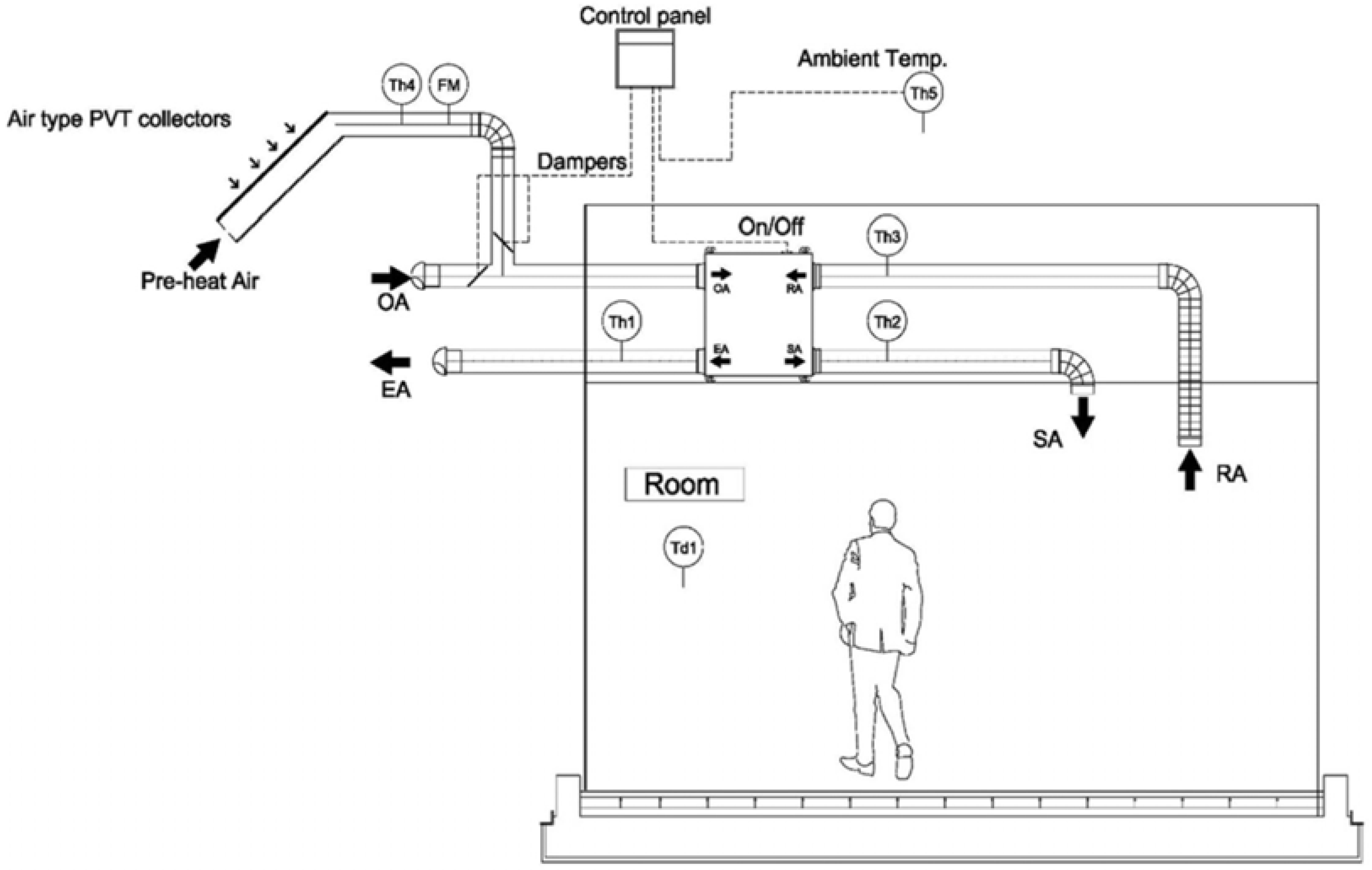
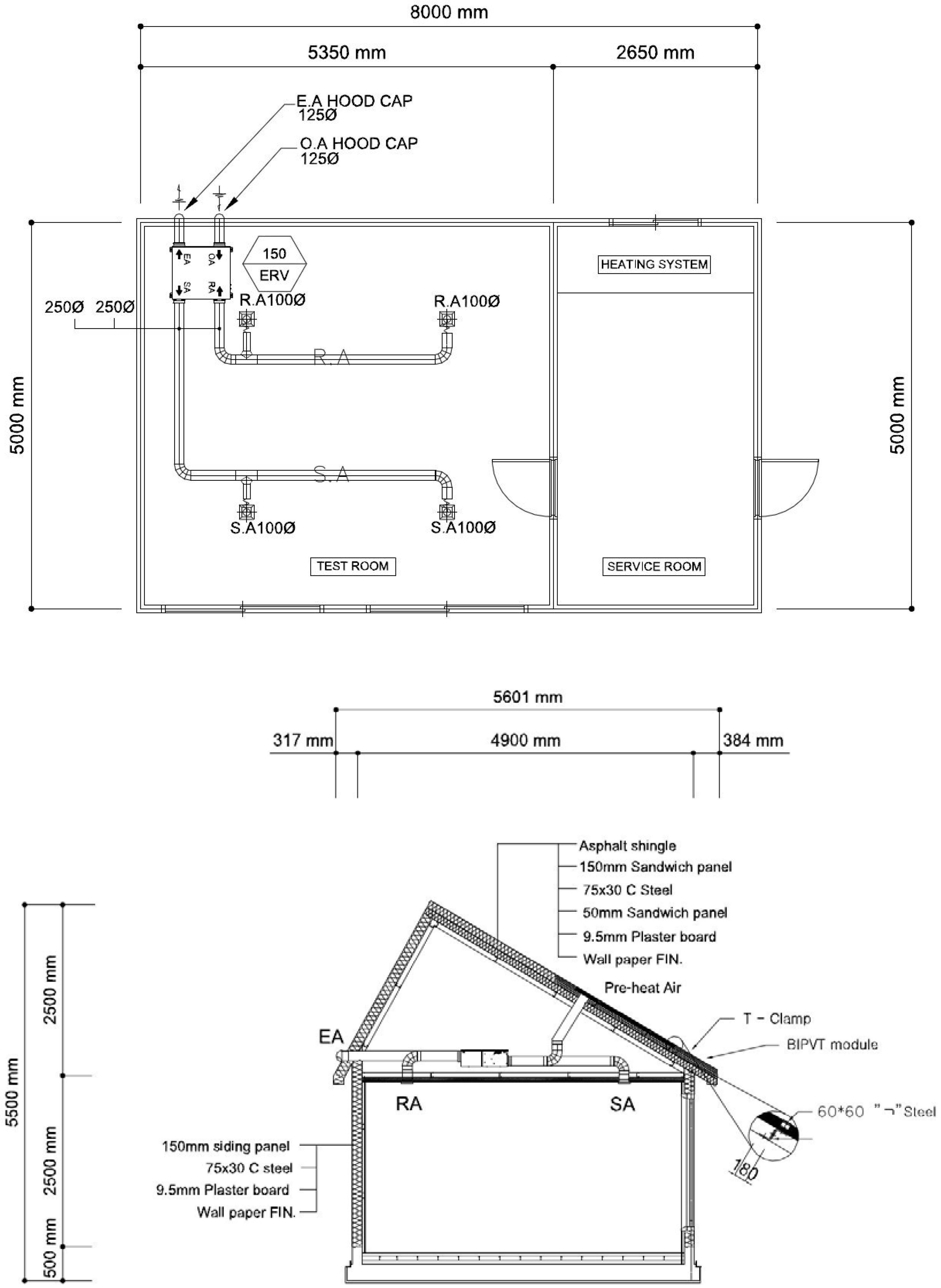
The test bed for the experiment on the PVT system coupled with the HRV was an experimental house which included a test room and a service room (see
Figure 4,
Figure 5,
Figure 6 and
Figure 7). The slope of the roof is 30°, and it was orientated toward the south. The experimental house included an electric heating system and an air-conditioning system.
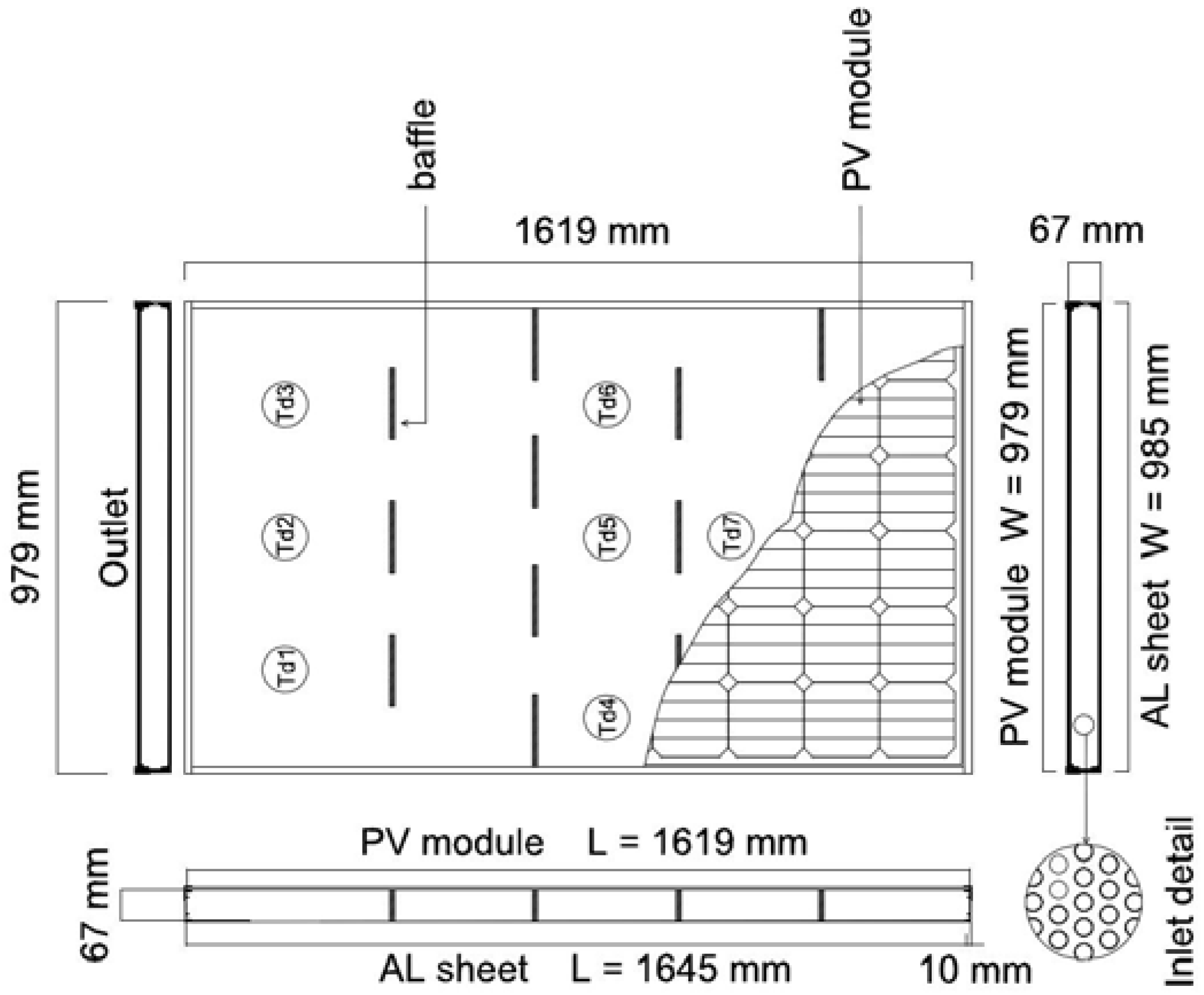
Four air-type PVT collectors were integrated into the roof of the experimental house as a substitute for the typical asphalt shingle roofing (
Figure 5). The power generation capacity was 1.0 kW
p, and the collecting area was 6.4 m
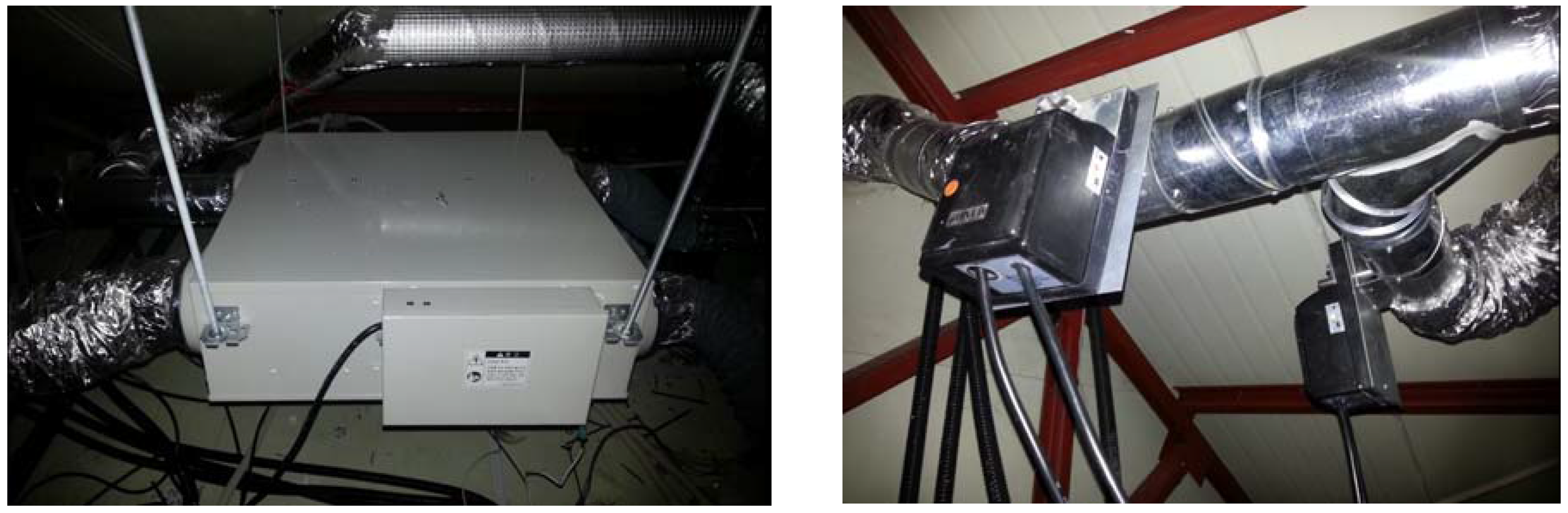
2. The PVT system consisted of one array composed of four serially connected modules with a maximum current of 8.23 A and a maximum voltage of 126.4 V. The air-to-air heat exchanger of the HRV system was installed in the space below the roof, together with the controller (
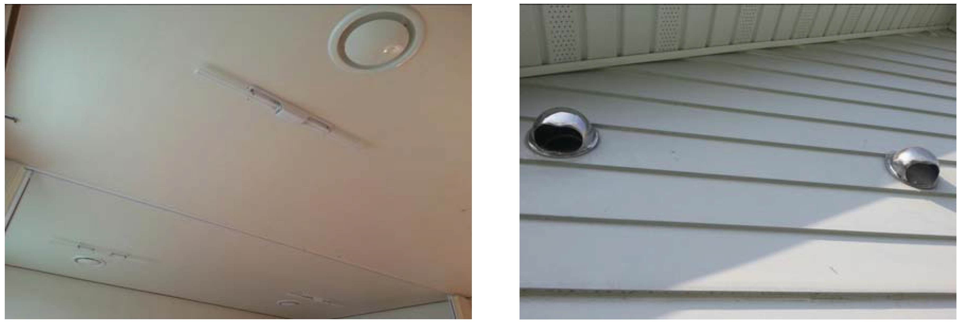
Figure 6). The four PVT collector outlets were combined into a single duct and connected to a duct branching out from the OA duct. The PVT collectors were coupled with the HRV system and operated using a control panel. Two supply air (SA) ducts and return air (RA) ducts were installed in the test room, while the OA duct and an exhaust air (EA) duct were installed on the back wall of the experimental house (
Figure 7). To prevent overheating of the collectors during the non-heating season, an additional duct was installed to vent the heated air to the outside of the house.
The two experimental modes used for the performance analysis of the PVT system coupled with the HRV were the PVT mode and the OA mode.
Similar to existing HRV systems, the OA mode introduces outside air into the heat exchanger and exchanges it with returned air to maintain a supply of fresh air indoors. Outside air enters the heat exchanger when dampers installed between ducts connecting collectors and the heat exchanger close while those near the OA duct remain open. For the PVT mode, air heated from the PVT collector is used as fresh air instead of outdoor air in the system. Heated air from the collectors enters the heat exchanger when the dampers near the OA duct close, while those installed between the ducts connecting the collectors and the heat exchanger remain open. A constant air flow rate (80 CMH) into the system and room temperature (20 °C) were maintained.
Measurements were taken of the radiation, outdoor temperature, indoor temperature, internal temperature of the PVT collectors, and the outlet temperature. The outdoor temperature and PVT outlet temperature were measured as the dry-bulb temperature (DBT) and the wet-bulb temperature (WBT), respectively. A flowmeter (FM), dry-bulb thermometers (Td), and temperature-humidity sensors (Th) were installed in the ducts, and a pyrheliometer was installed on the roof. An electrical load resistor (7.36 A, 17.3 Ω) and a power meter (Yokogawa WT230, Yokogawa Electric Corporation, Tokyo, Japan) were installed in order to measure the electrical performance of the PVT system. All data related to the thermal and electrical performance of the PVT system were monitored and recorded at 10s intervals through a data acquisition system (Agilent 34970A, Agilent Technologies , Santa Clara, CA,USA).
The experiment on the PVT system coupled with the HRV was conducted in March 2015. The electric floor panel heating system was activated to heat the test room, and the energy consumption of the heating system was measured to calculate the heating energy.
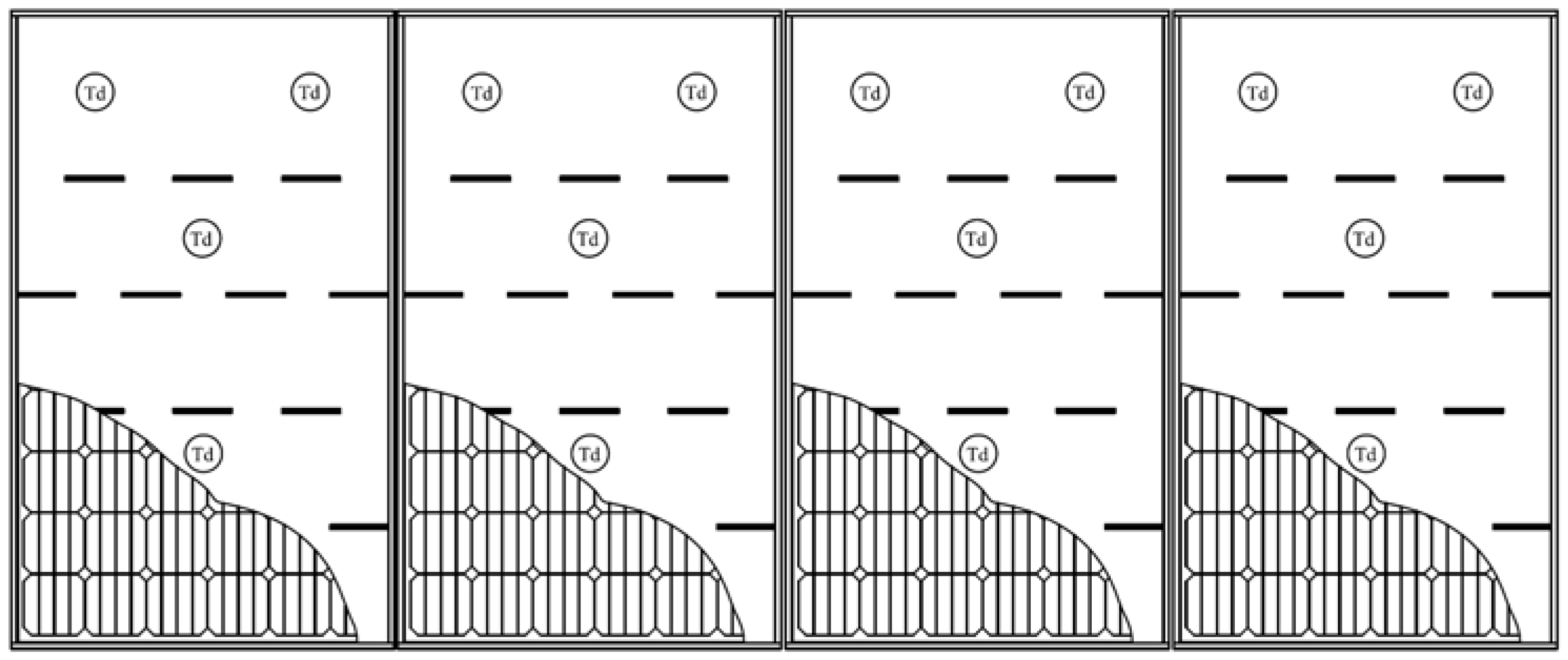
The air heated by the PVT collectors during the non-heating season must be released outside of the house to prevent overheating of the PV modules. An exhaust duct and a fan were installed for this purpose. The PV temperature was measured using a temperature sensor installed on each of the four PVT collectors (
Figure 8). The same experiment was conducted with and without operation of the fan to release the heated air.
3.2. Results and Analysis
3.2.1. Temperature Characteristics of the PVT Collector
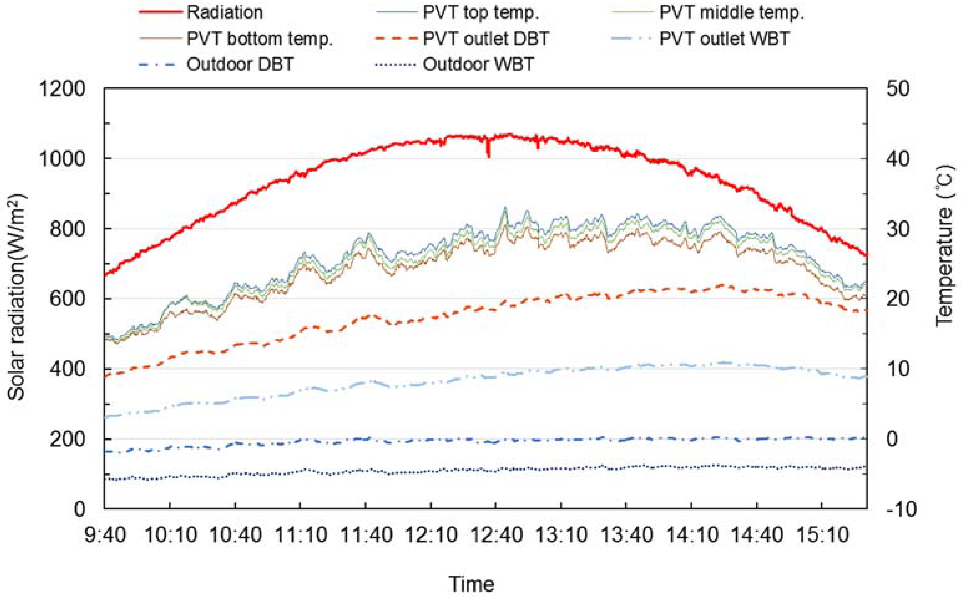
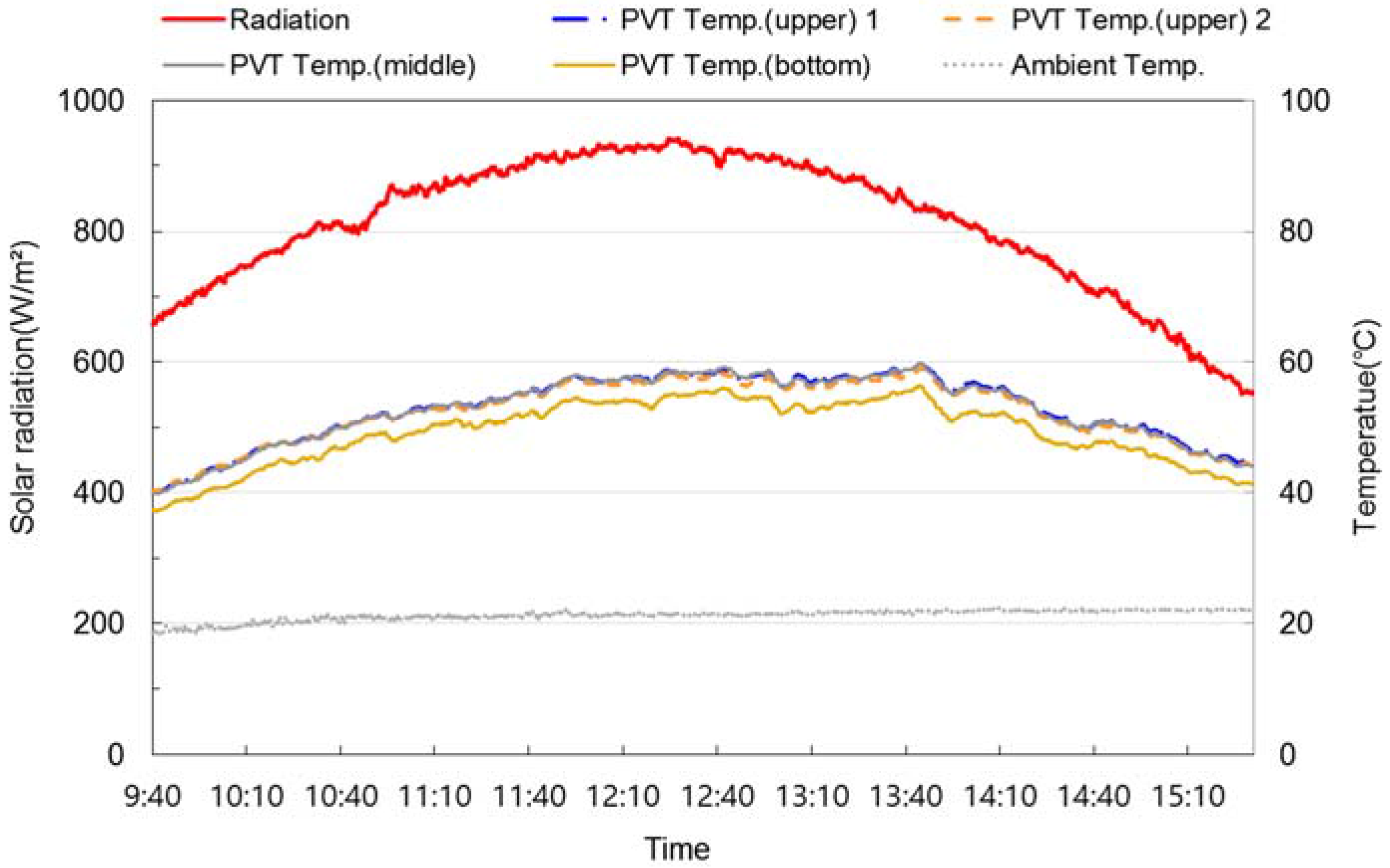
Figure 9 shows the temperature characteristics of the PVT system with the HRV on a clear day. The graph presents details of the solar radiation, outdoor temperature, the PVT DBT and the PVT WBT. The outdoor DBT was −2–0 °C, the outdoor WBT was approximately −5 °C and the solar radiation reached a maximum of 1080 W/m2. The temperature range of the air space (bottom, middle and top) in the PVT collector was 14–22 °C. The outlet DBT and WBT components had temperature ranges of 9–22 °C and 3–10 °C, respectively. The temperature difference between the PVT outlet air and the outdoor air was in the approximate range of 10–20 °C. The cold outdoor air was heated through the collector during the heating season. Therefore, problems with the HRV, such as freezing and dew condensation caused by the cold outdoor air, could be prevented with the air pre-heated by the PVT collector. In addition, the required heating energy could be reduced and efficient ventilation was ensured with the high-temperature supply air.
3.2.2. Thermal and Electrical Performance of the PVT System with the HRV
Regarding the experimental results of the PVT system with the HRV, the thermal and electrical performances of the PVT system were analyzed. The thermal efficiency is calculated as ratio of the heat gain energy from the PVT collector (
Q2) to the incoming solar radiation on the PVT collector (
Q1) by the equation given below. The thermal and electrical efficiency levels were calculated using Equations (2) and (3), respectively:
Apvt: Surface area of the collector (m
2);
Cp: Specific heat of air at a constant pressure (J/kg·°C);
G: Solar radiation (W/m
2);
ṁ: Mass flow rate (kg/h);
To: Outlet air temperature of PVT (°C);
Ti: Inlet air temperature of PVT (°C); η
th: Thermal efficiency (-).
η
el: Electrical efficiency (-);
Im: Maximum current (A);
Vm: Maximum voltage (V).
For this study, the PV power output from the load resistor and a micro-inverter with maximum power point tracking (MPPT) were measured under outdoors conditions. The power output levels were analyzed and compared in the experimental results. The PV power output levels in the two cases according to the solar radiation are shown in
Figure 10. It was found that the power output of the PV with load resistor is lower than that of the PV with a micro-inverter at solar radiation levels below 600 W/m
2. However, the PV in both cases had very similar power output levels when the solar radiation exceeded 600 W/m
2. Therefore, it was concluded that the power output of the PV from the load resistor without MPPT is valid when the solar radiation exceeds 600 W/m
2.
Figure 11 shows the daily thermal and electrical performance levels of the PVT system. With average solar radiation of 750–1000 W/m
2, the total solar radiation gain is 5.9 kW on average. The gain in the thermal and electrical energy of the PVT system was 2.2 kW on average, translating into a thermal efficiency of 23% and electrical efficiency of 15%.
3.2.3. Heating Energy Demand During the Heating Season
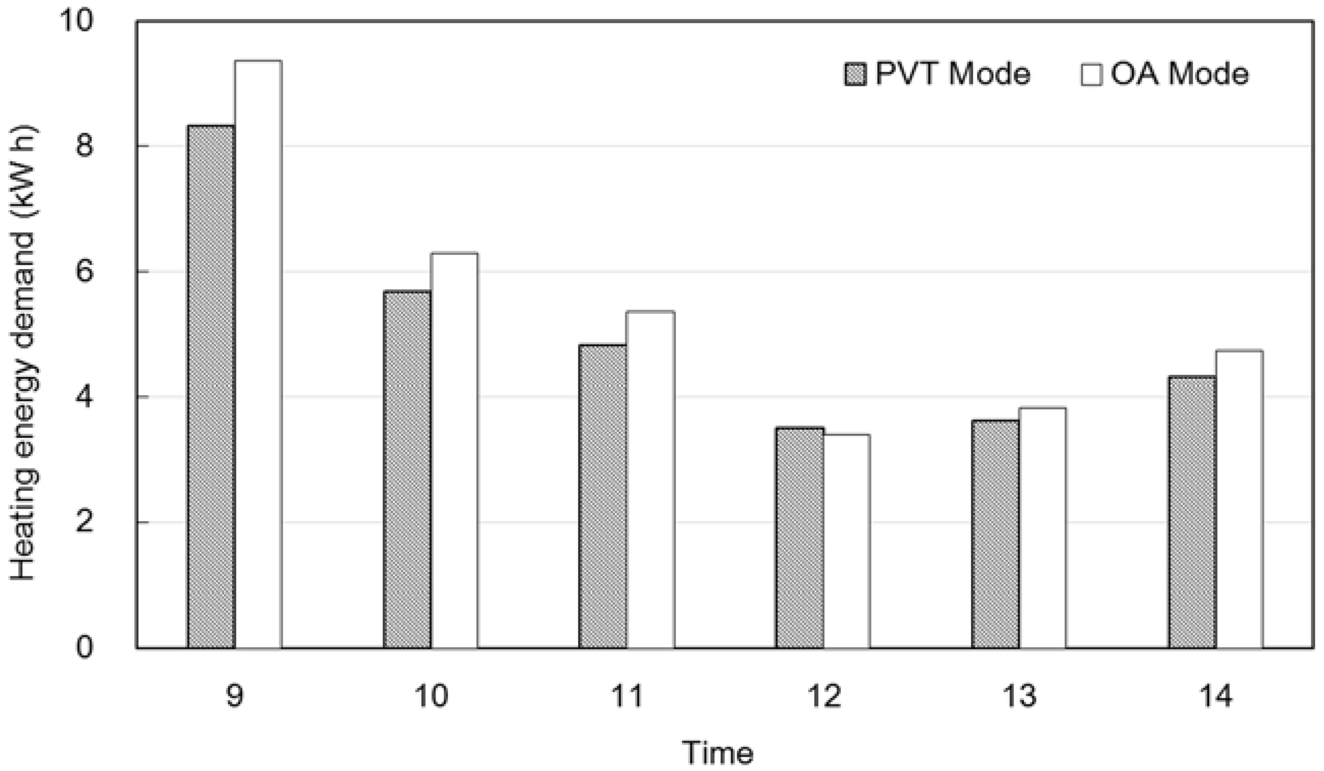
Figure 12 shows the heating energy demand for the experimental house with the two modes according to the time of day. According to these results, the heating energy demand in the PVT mode and the OA mode during the day are approximately 30 kWh and 33 kWh, respectively. In the two modes, the difference in the heating energy demand for the experimental house is close to 3 kWh, indicating that the heating energy of the OA mode is nearly 10% higher than that of the PVT mode. These results demonstrate that the use of heated air from the PVT collector allows the HRV system to reduce the heating energy demand level.
3.2.4. Temperature and Electrical Characteristics of the PVT System during the Non-Heating Season
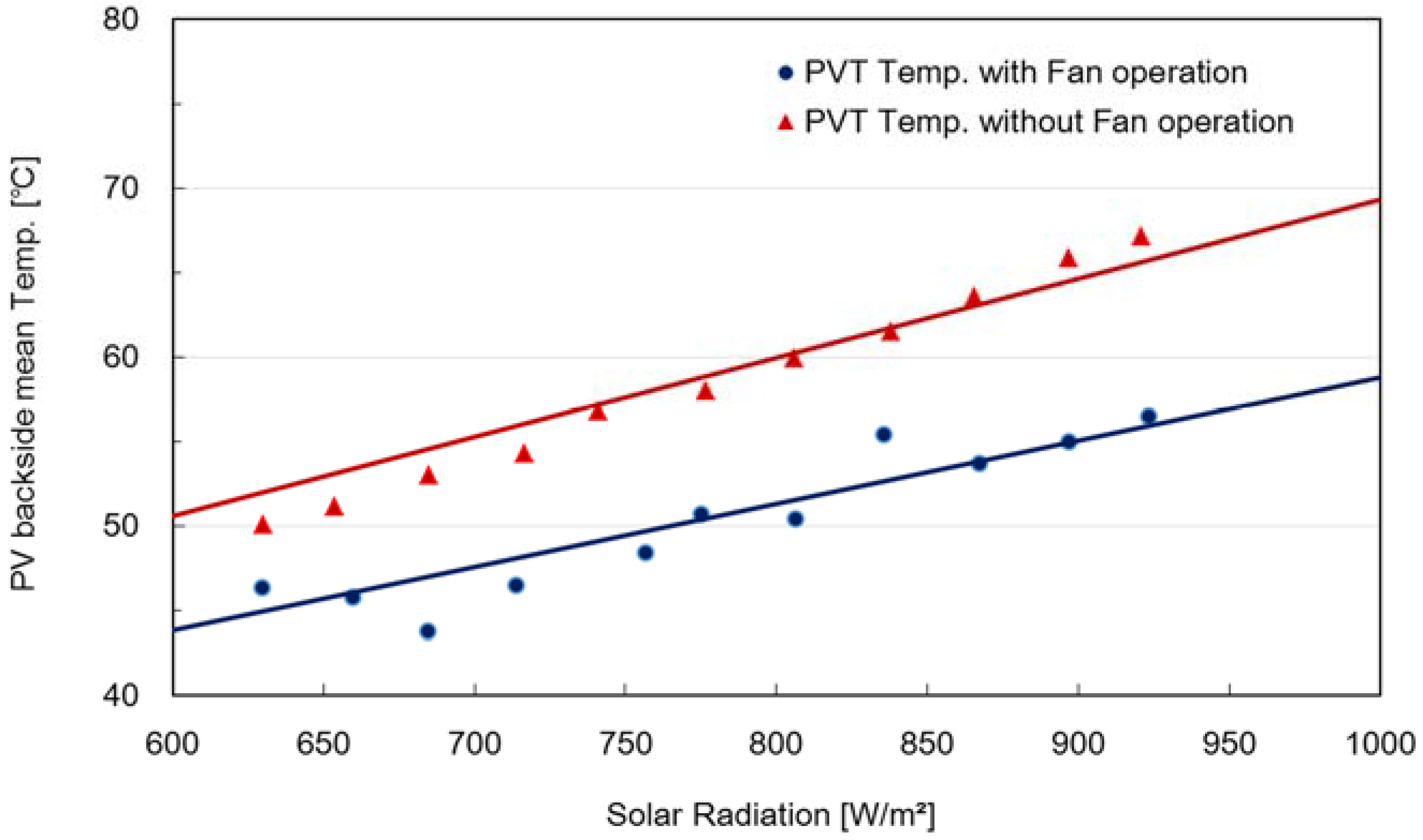
Figure 13 shows the PV temperature of the PVT system with the HRV with and without the operation of the fan on a clear day in the non-heating season. The two days displayed in the graphs have similar outdoor conditions, with an outdoor temperature of 20 °C and average daily radiation of 800 W/m
2. The PV temperature range was 39–58 °C when air is released through the operation of the fan, and it is 44–69 °C in the case of natural convection. When heated air is released through the operation of the fan, the PV temperature at the upper part of the collector was 5 °C higher than that of the bottom part, which results in a slight gap in the graph. On the other hand, in the case of natural convection, the PV temperatures for the upper, middle and bottom parts were uniform at all points of measurement. The PV temperature was lowered by about 10 °C when the fan was operated.
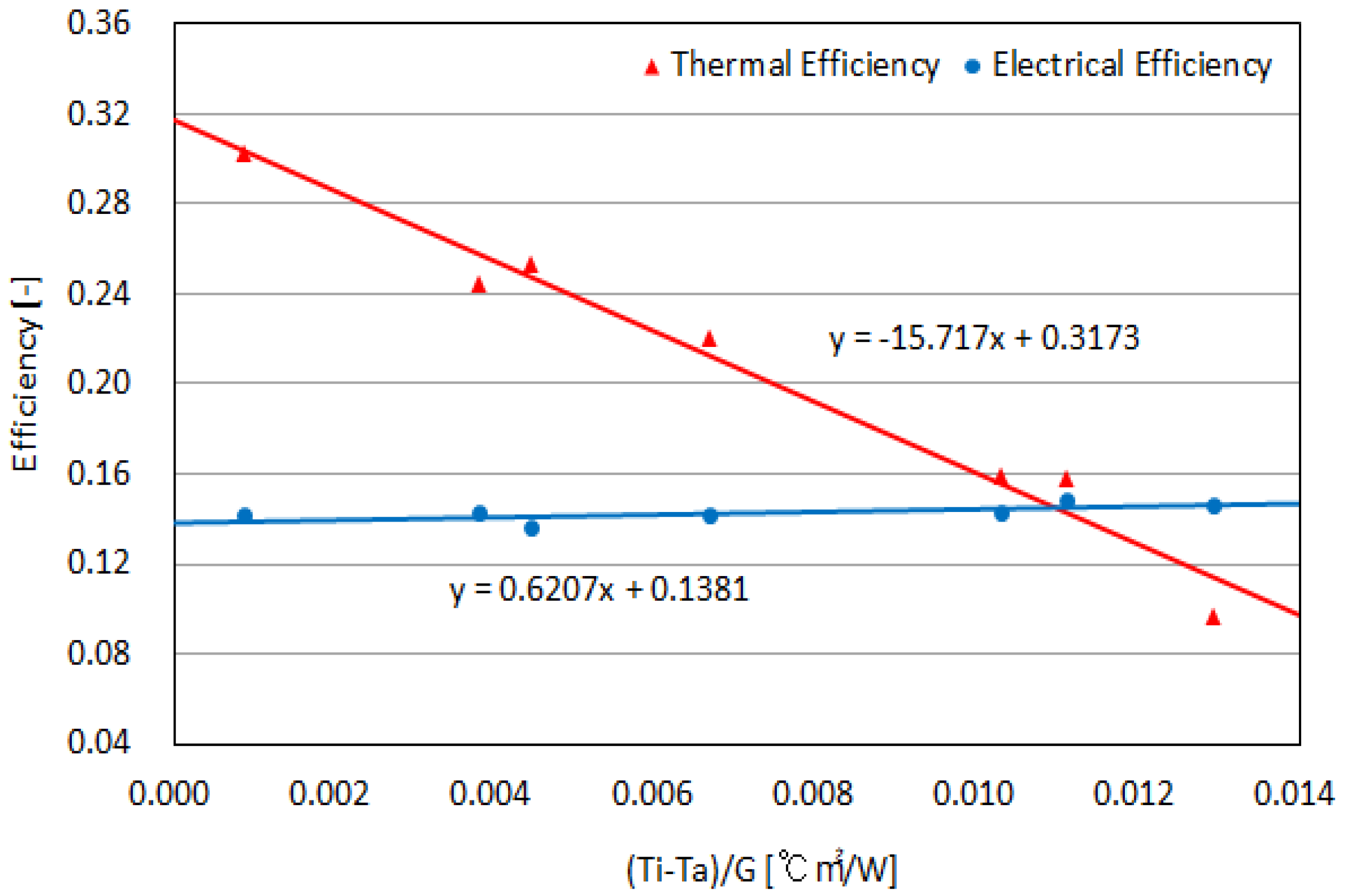
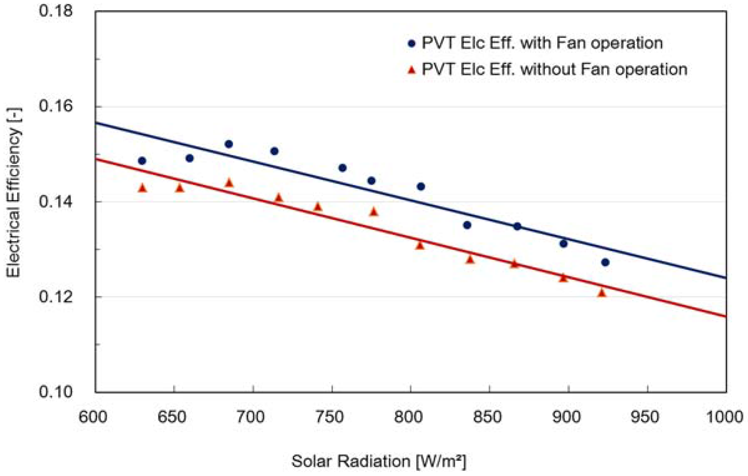
The graph below compares the electrical efficiency of the PVT with and without operation of the fan during the non-heating season (
Figure 14). The maximum electrical efficiencies of the PVT with and without the fan are 0.152 and 0.144, respectively, and the minimum electrical efficiency rates are 0.127 and 0.121, respectively. These results show that the electrical efficiency of the PVT system with the operation of a fan is approximately 10% higher compared to the PVT system without a fan. This difference appears to be significant, as it reflects a difference of about 0.8 points with reference to the overall electrical efficiency of the PVT system. On the other hand, the average electrical efficiency rates of the PVT system with and without the operation of a fan were found to be approximately 14.2% and 13.4%, respectively. To analyze the effect of operating a fan on the electrical performance of the PVT system, the PV backside temperatures of the PVT system were analyzed. These values were compared according to the solar radiation (
Figure 15). The PV temperatures of both PVT systems with and without the fan rise according to an increase in the solar radiation. With a similar solar radiation level, the PV temperatures of the PVT without a fan were higher by an average of 8 °C as compared to those of the PVT system with a fan.
As such, a fan can be considered a requirement during the non-heating season to optimize the electrical performance and prevent overheating. The PVT system with the HRV saves heating energy by heating the outside air and exchanging it with the indoor air. Furthermore, during both the heating and non-heating seasons, the electrical efficiency can be improved through the release of the air heated by the system.
4. Conclusions
In this study, an air-type PVT system with a HRV was designed and then installed in an experimental house to analyze the thermal characteristics of the PVT system and the energy performance of the house. The electrical efficiency of the PVT system in the non-heating season was compared for cases with and without the operation of a fan.
According to the experimental results, the PVT system with the HRV had an overall efficiency rate of 38% based on its thermal and electrical performance levels during the heating season. The PVT system with the HRV used 10% less heating energy than the existing HRV system. The electrical efficiency improved by nearly 10% when air was released using a fan during the non-heating season. When the HRV system releases air naturally without a fan during the non-heating season, the PV temperature rises to almost 70 °C, which can result in lower efficiency. To prevent this, careful considerations must be made to control the gain in thermal energy during the non-heating season.
The air-type PVT system with the HRV is able to reduce the heating energy consumed in buildings and enhance PV generation efficiency. As such, the proposed system can be widely applied to reduce energy usage levels in buildings. The performance of the PVT system and existing facilities rely on proper system integration and operation. Continuous efforts should be exerted to ensure the optimal performance of the PVT system and its smooth integration into existing facilities.


