1. Introduction
The Velenje colliery is among the largest in Europe, as well among those with the most modern equipment. Positioned in the north-eastern region of central Slovenia, in the midst of the tectonic depression that is part of the Šalek Valley, it is packed with more than 1,000 m of Pliocene sediments. The latter exemplify a full sedimentation cycle, covering, in both directions, the terrestrial, swamp and lake phases of such a cycle. This progression is occasionally interrupted by fluviatile sediments coming from the north or north-west [
1].
Beginning in the final years of the 19th century, coal extraction has continuously been taking place in the Velenje coal mine. From this time until present day, several methods of excavation of wide coal have been tested. In the first half of the 20th century, room, pillar and block caving were employed, while in the latter half, an improved longwall mining method named the Velenje longwall method became the favourite [
2,
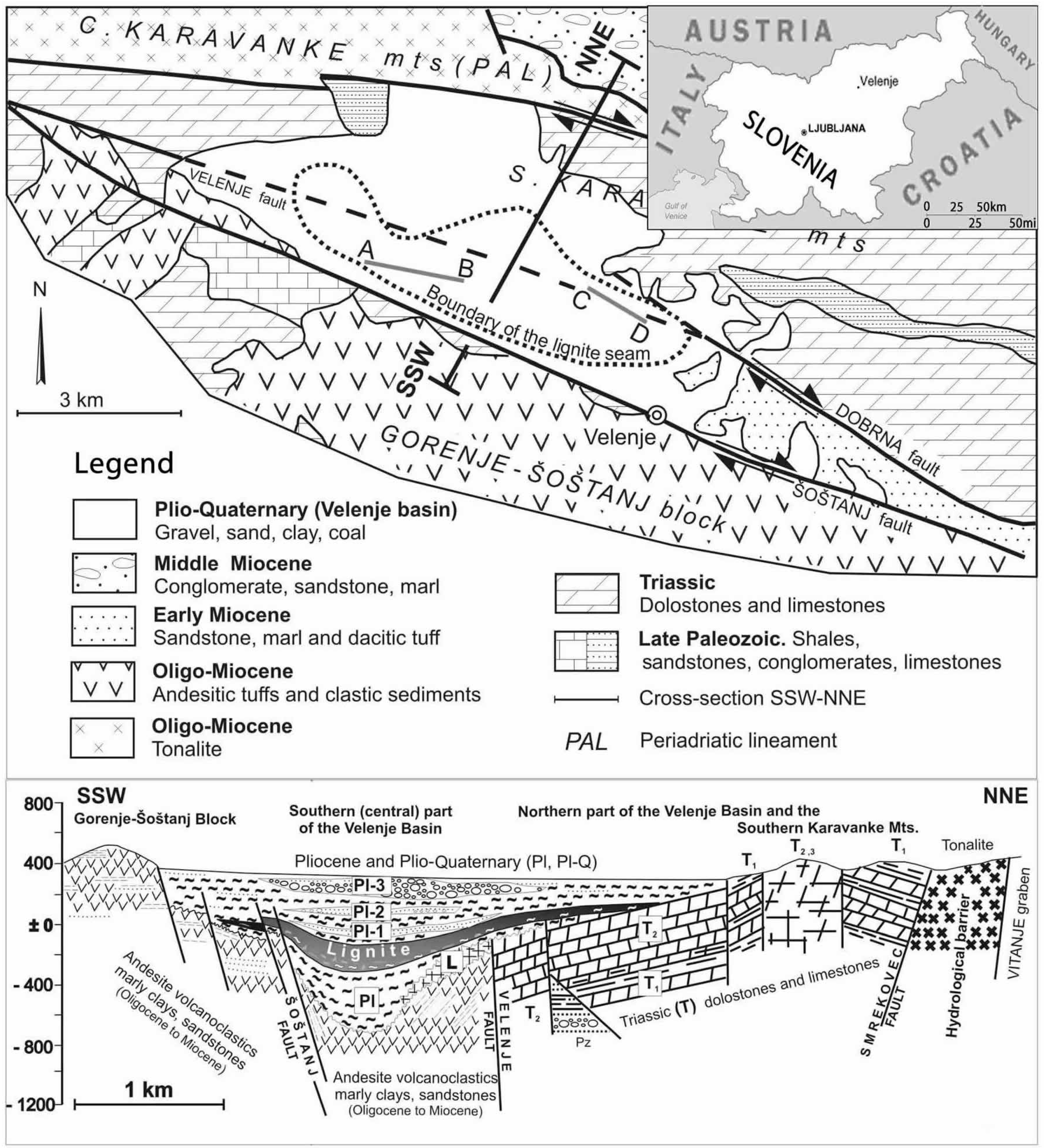
3]. Taking advantage of the truly astonishing dimensions of its coal seam, an approximately continuous body measuring 8.3 km in length, 2.5 km in width, more than 160 m in thickness and anywhere from 200 m to 500 m in depth, the Velenje colliery produces lignite. In its centre, the exploitable part of the coal seam measures up to 168 m in thickness and is deposited at a depth of approximately 450 m. In its margins, the seam is nearer the surface, with a deposited depth of only approximately 100 m, as seen in
Figure 1 [
4]. In its lower part, there is an increase of ash content in the seam, however, its upper margin is immensely sharp. The seam lies beneath a covering of marlstone, as well as beneath either laminated or massive mudstone as part of which water-bearing sands or leans of gravel of altering size appear.
There is also what is called an isolation or protection layer positioned above the coal seam and beneath the sands that cover it. This layer keeps water or mud from spilling into the excavated areas of the colliery [
2]. However, when large, open areas are mined, the protective layer is in danger of cracking, which would result in the multiple layers of sand and gravel aquifer lying above the lignite seam coming into contact with it. As a result of this, in the multilayered aquifer, groundwater pressure must be monitored at all times [
6,
7] and models of the groundwater situation must be created in order to predict the underground hydrological situation.
In the past, the standard way to do this was using FDM numerical models, while the most effective predictions pertaining to the Velenje colliery were obtained through the use of Visual ModFlow. However, in spite of its success and popularity in Velenje, the former is limited in terms of its ability to make predictions about the hydrological situation in the short term, a well-known problem to which different potential solutions may be applied [
8]. At the centre of this problem is the fact that the FDM method produces models of groundwater drawdown that are not as reflective of the fluid's movement as of its cell size [
9].
In terms of the hydrological situation, in Velenje, three different hydro-geological systems can be found: the upper Quaternary, the Pliocene-Quaternary and the Pliocene [
2,
3,
7,
10]. The upper Quaternary system is topmost, the Pliocene-Quaternary at its lower border and the Pliocene in the lowest position. The latter is also separate from the coal seam, a consequence of both the previously mentioned isolation layer and the floor aquifers that are present within the aquifer layers of the Triassic dolomites to the north of, the lithotomic limestone in the centre of, and the Pliocene layer above the coal seam [
4]. In 1981, roof aquifers were divided into Quaternary and Pliocene aquifers, based on the degree of groundwater in a single aquifer, as well as on reactions to pumping, chemical analysis and geophysical characteristics [
10,
11,
12,
13]. The Pliocene aquifers were further divided into three categories, namely the aquifers directly above both the coal seam and the layer of isolation directly above it, Pl1, the aquifers lying from 20 m to 80 m above the coal seam, Pl2, and the aquifers lying where the upper Pliocene layer is, Pl3 [
1,
5,
7,
13,
14,
15]. Examining the division from a point of view that prioritises safety, the Pl1 and Pl2 aquifers are the most crucial to keep an eye on, as the high degree of pressure present inside them can directly affect the underground works being done in their immediate vicinity [
1,
7,
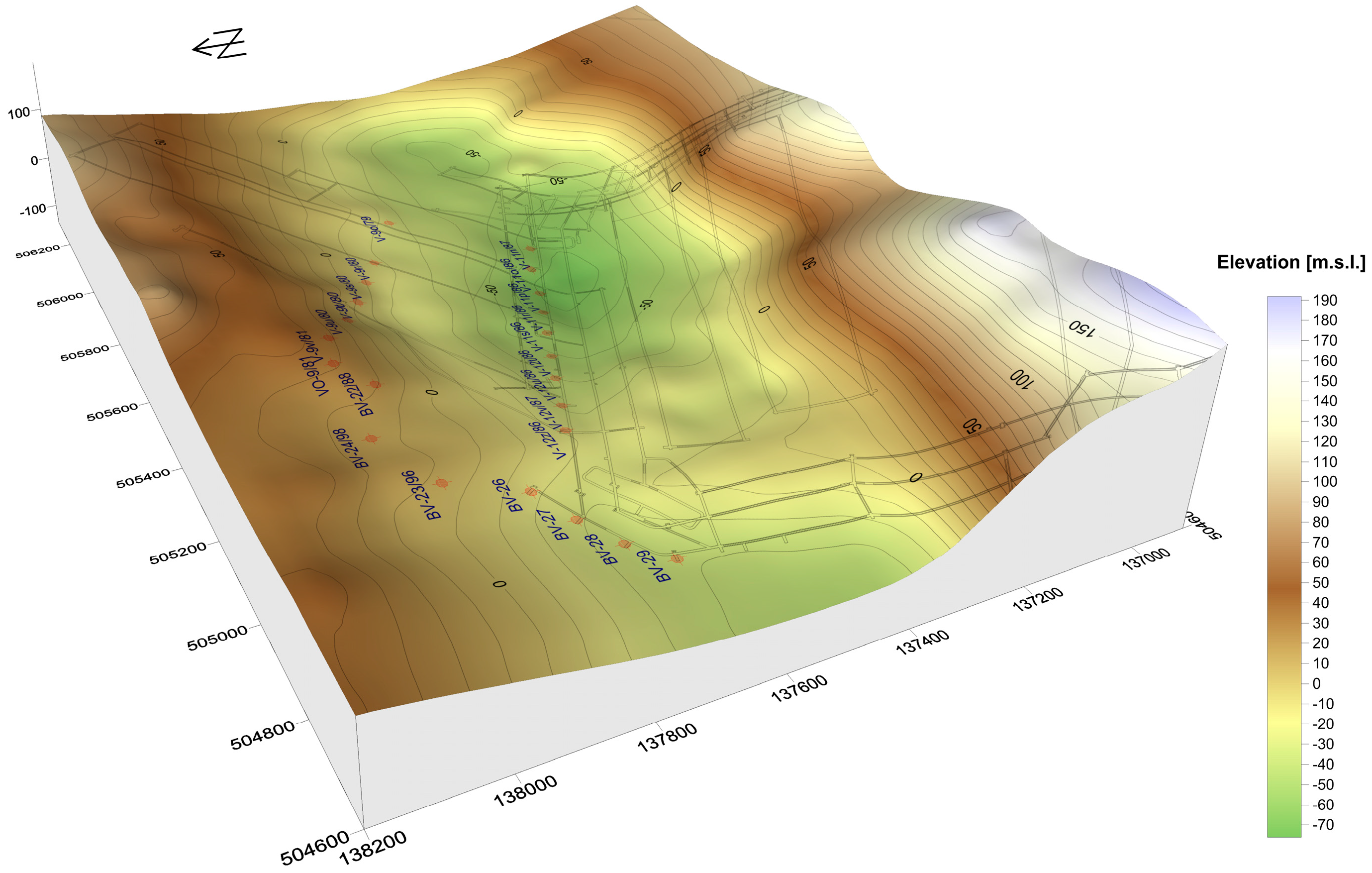
10]. As an illustration the degree to which the first, Pliocene sand-bearing waters have increased in the year 2007 is displayed in
Figure 2 below.
2. Materials and Methods
It is evident from previous studies [
1,
2,
3,
7,
10,
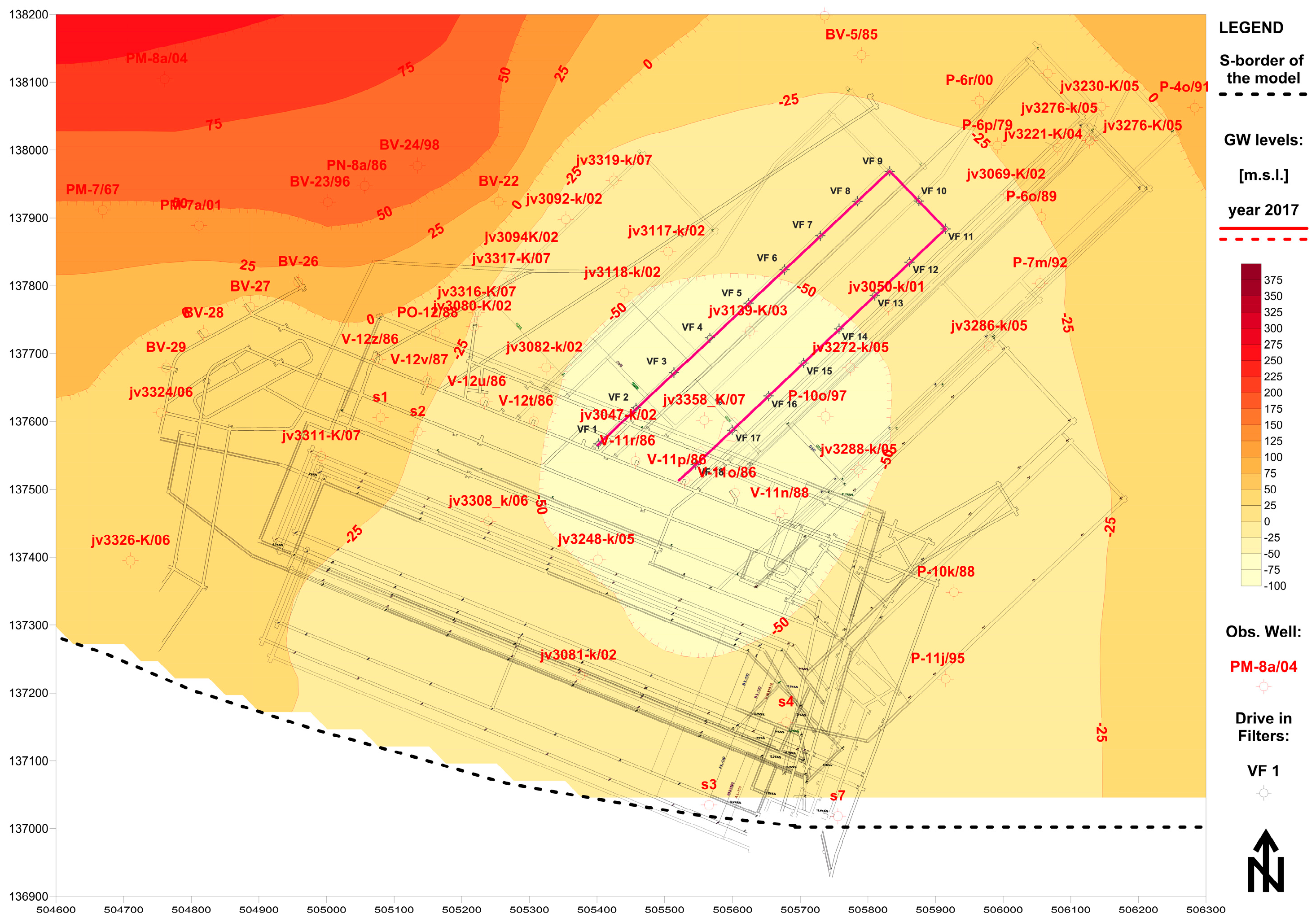
14] that underground works on the coal seam in Velenje will inevitably lead to an increased presence of open spaces in the coal seam, into which the materials lying above with ground water in it will tend to seep. The effects of mining in the Velenje colliery will also affect the rates of pumping, and the pumping wells depicted using red circles in
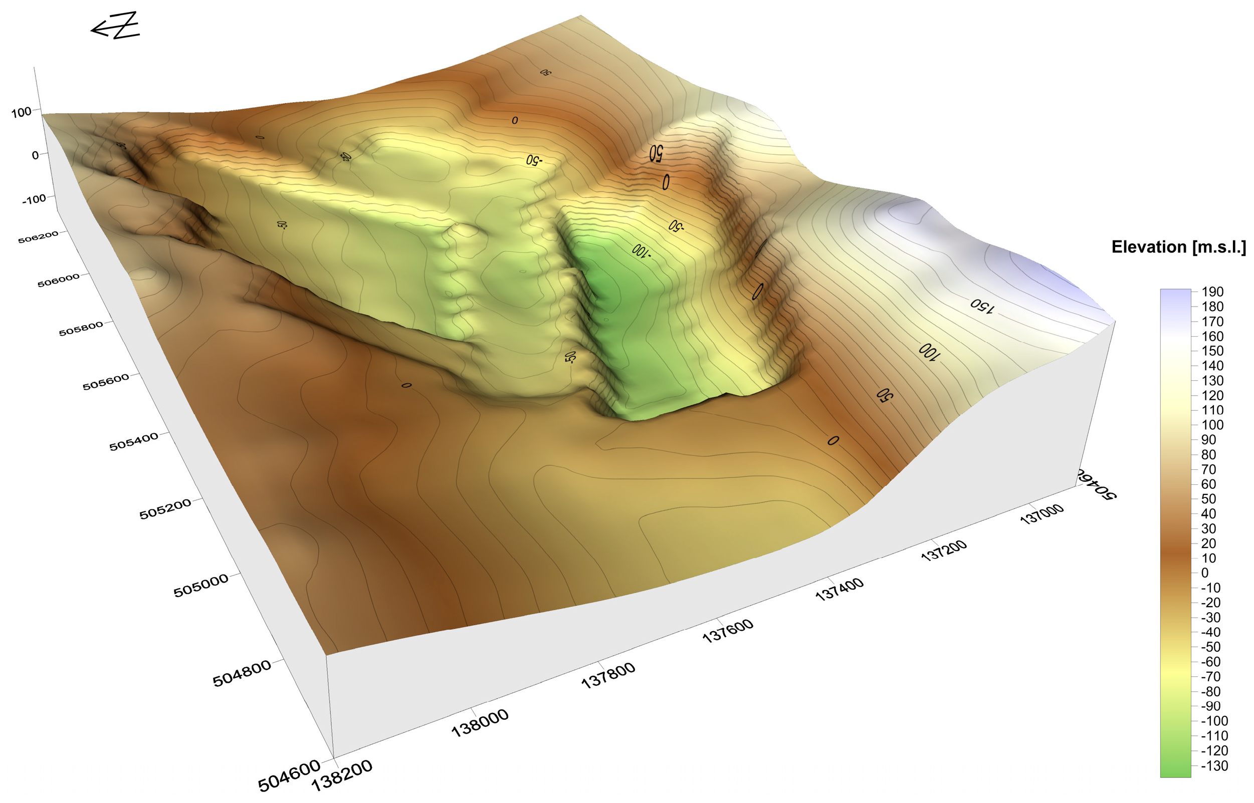
Figure 2 are expected to stop being workable in 2017, a result of the means of coal excavation directly beneath the wells. Consequently, the elevation of Pl-1 and Pl-2 is expected to change to the situation depicted in
Figure 3.
As it turns out, the pressure levels in the groundwater in the Pl-1 and Pl-2 sands are crucial [
1,
2,
3,
7,
10,
14]. Employing data obtained with the aid of multilevel piezometers, the authors of this article were able to establish groundwater level, as depicted in
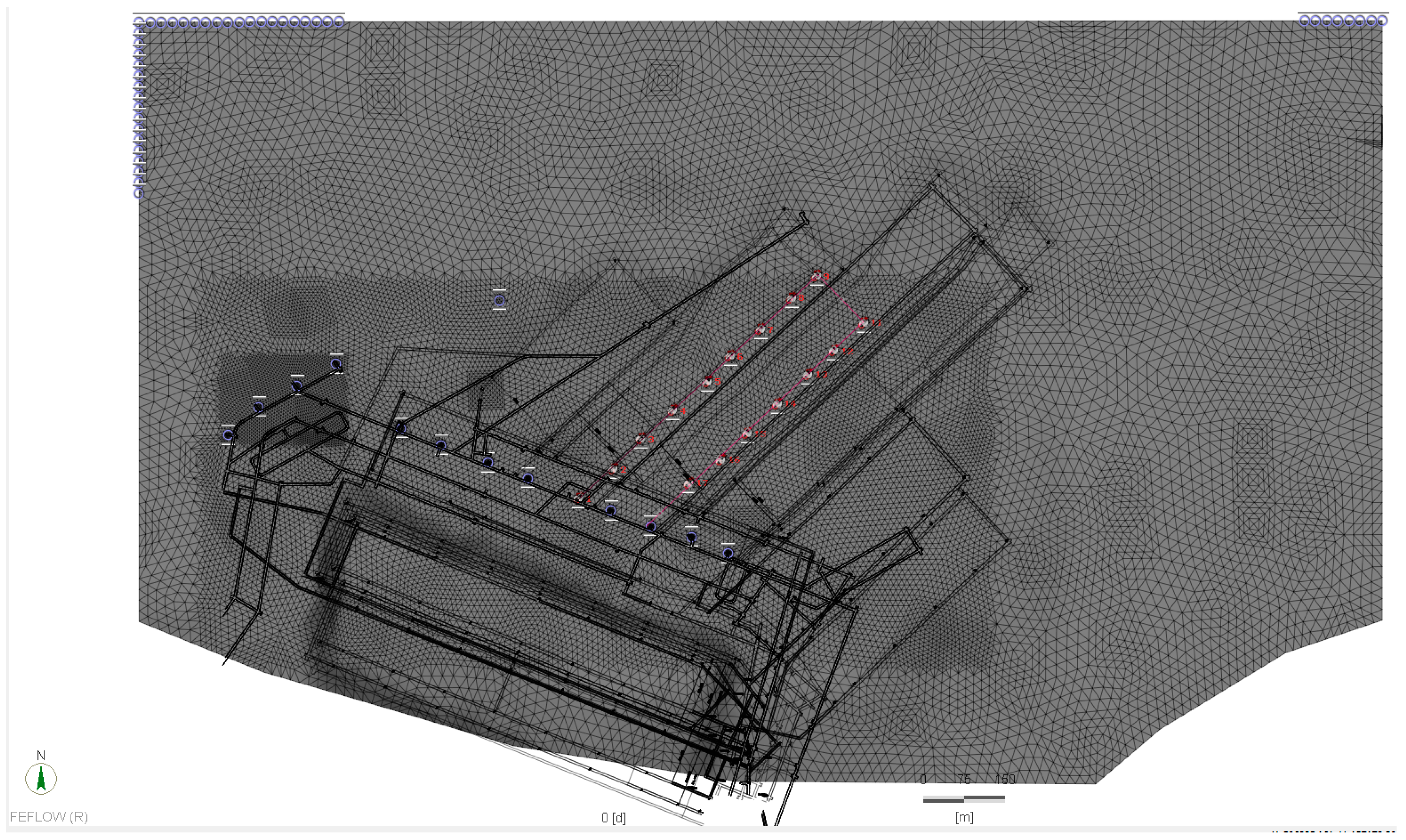
Figure 4. It is evident that groundwater depression will result from the practice of long-term dewatering in the colliery that is a result of water extraction using pumping wells. In order to minimise the effects of such closed pumping, thus-named drive-in filters will be implemented at the bottoms of vertical pumping wells, as depicted in
Figure 4. These drive-in filters will not start functioning simultaneously, but will start and stop their function depending on the process taking place at the time as part of the longwall excavation method.
3. Results and Discussion
In order to be able to predict the effects of material seeping from above into the coal seam in the Velenje colliery, it was necessary to shut down the excavation battery as part of mining and replace the shut-down wells with drive-in filters strategically placed around the longwall face that was at the entrance and exit points of tunnels, as presented in
Figure 4. For this, a 3D FEM was used, while for modelling purposes, a FeFlow 6.1 program used to model flow, mass and heat transfer was chosen.
Having obtained the grids displayed in
Figure 2 and
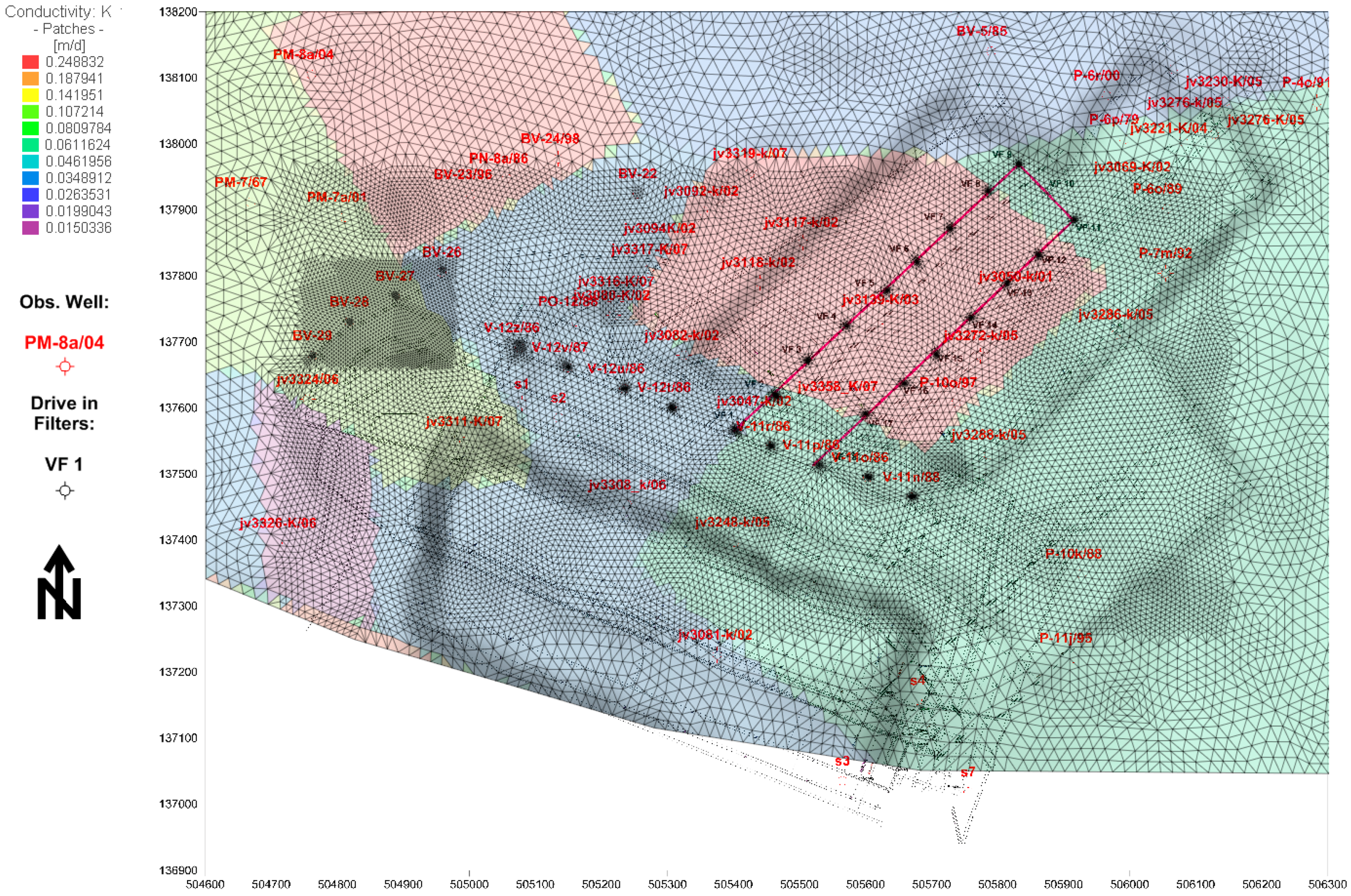
Figure 4, the authors first calibrated the model using FeFlow 6.1 so that it would reflect the current hydrological and mining situation, and then defined the calculated and calibrated model to the initial condition. Model calibration was performed primarily by changing the values in areas (
Figure 5) with different hydraulic conductivity (k) using PEST. The different hydraulic conductivity areas were defined according to prior pumping test and to FDM results [
1,
3,
7,
10,
14]. The inflows from the northern, north-western and north-eastern parts were also taken in account during the calibration and compared with previous findings [
1,
3,
7,
10,
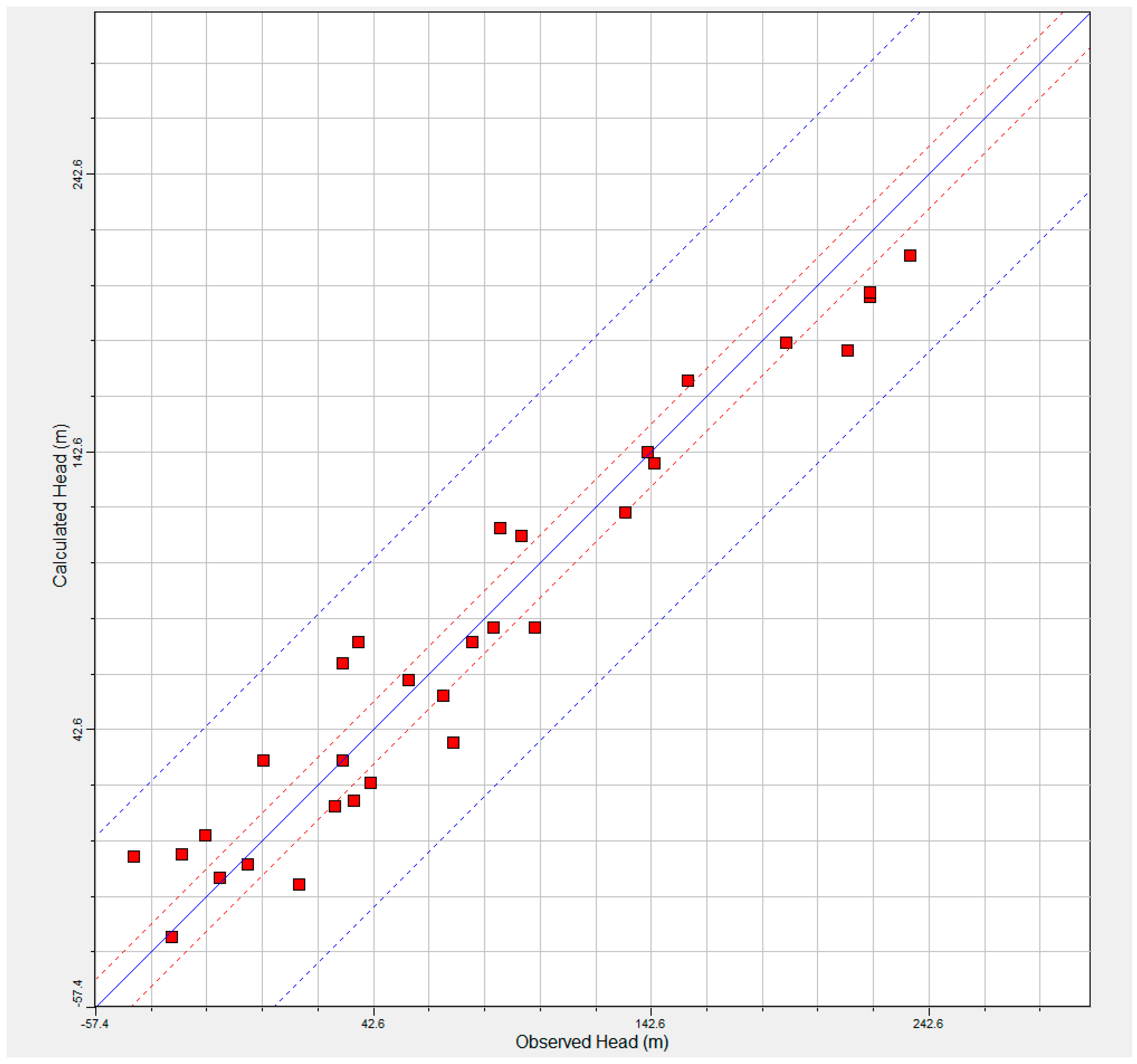
14]. The results of modeling are new values of (k) (
Figure 5) with the RNMS around 7.49% (
Figure 6). As mentioned before, in order to determine the boundary of flow, the authors chose the Dirichlet boundary condition for the northern, north-western and north-eastern parts of the model, as depicted in
Figure 7. Extraction from old, residual wells was selected to have a single source or boundary, as is also depicted in
Figure 7. The selected pumping rates were simply the averaged pumping rates beginning with the year 2005 and ending with the year 2006. The estimated underground well pumping rates were determined by a Dirichlet boundary condition, the heads of which were kept to the planned groundwater level (
Figure 7). The model was also designed in such a way as to take into account the beginning and ending spots of underground vertical wells (Time constrains condition inside FeFlow 6.1 were applied).
In
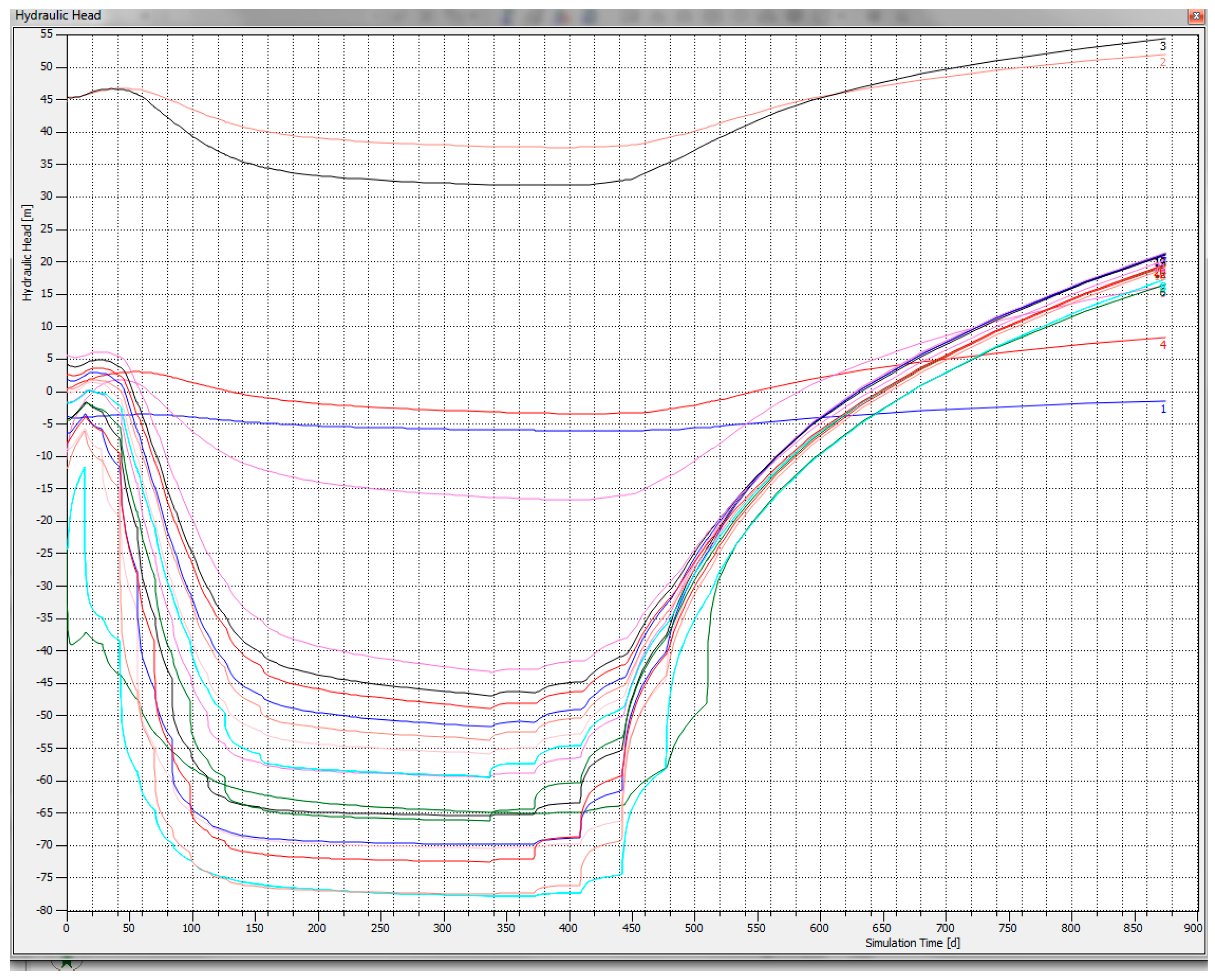
Figure 8, the largest expected depression of groundwater in m.s.l., as a result of numerical modelling calculations using the methodology described in the following section, is displayed. The former is to be encountered in the 360th day of work on the longwall face according to the pertinent mathematical model made in FeFlow 6.1. As is evident, the depression is the largest in the area of the underground vertical wells and, examining the development of the groundwater depression presented in
Figure 8, it could be asserted that the dewatering that is a result of underground vertical pumping wells has had a significant impact. If it is considered that the bottom at this stage of excavation is at 10 m.s.l., and if
Figure 9 is also closely examined, it is possible to ascertain that the dewatering will be immensely effective and that after excavation is stopped at the drive-in filters, groundwater will begin to rise up and flood the entire area in less than 150 days.

