Article

Research on the Combustion Characteristics of a Free-Piston Gasoline Engine Linear Generator during the Stable Generating Process

1
School of Mechanical and Vehicle Engineering, Beijing Institute of Technology, Zhongguancun South Street No. 5, Beijing 100081, China
2
Sir Joseph Swan Centre for Energy Research, Newcastle University, Newcastle upon Tyne NE1 7RU, UK
*
Author to whom correspondence should be addressed.
Energies 2016, 9(8), 655; https://doi.org/10.3390/en9080655
Submission received: 29 May 2016 / Revised: 8 August 2016 / Accepted: 11 August 2016 / Published: 18 August 2016
(This article belongs to the Special Issue Combustion and Propulsion)

Abstract

:
The free-piston gasoline engine linear generator (FPGLG) is a new kind of power plant consisting of free-piston gasoline engines and a linear generator. Due to the elimination of the crankshaft mechanism, the piston motion process and the combustion heat release process affect each other significantly. In this paper, the combustion characteristics during the stable generating process of a FPGLG were presented using a numerical iteration method, which coupled a zero-dimensional piston dynamic model and a three-dimensional scavenging model with the combustion process simulation. The results indicated that, compared to the conventional engine (CE), the heat release process of the FPGLG lasted longer with a lower peak heat release rate. The indicated thermal efficiency of the engine was lower because less heat was released around the piston top dead centre (TDC). Very minimal difference was observed on the ignition delay duration between the FPGLG and the CE, while the post-combustion period of the FPGLG was significantly longer than that of the CE. Meanwhile, the FPGLG was found to operate more moderately due to lower peak in-cylinder gas pressure and a lower pressure rising rate. The potential advantage of the FPGLG in lower NOx emission was also proven with the simulation results presented in this paper.

1. Introduction

Because of the consumers’ demand for low fuel consumption and the stringent governmental emission legislation, researchers all over the world have been devoted to improving the technologies in the traditional internal combustion engine, as well as investigating new kinds of power machinery for energy conversion [1,2,3,4,5]. The free-piston engine linear generator (FPLG), as one of the new energy conversion devices, has been widely studied due to its potential advantages of high efficiency, low emissions and multi-fuel capability over the conventional engines [6]. The FPLG is a combination of free-piston engines and a linear generator. According to the amount of the piston and the arrangement form, it can be divided into three categories, that is the opposed piston free-piston engine, the single-cylinder free-piston engine and the dual piston free-piston engine [
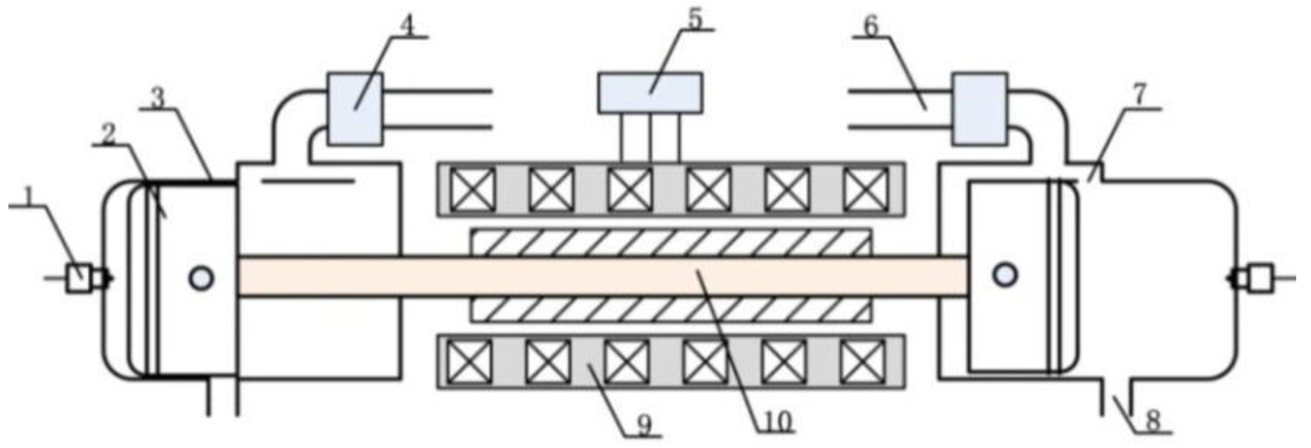
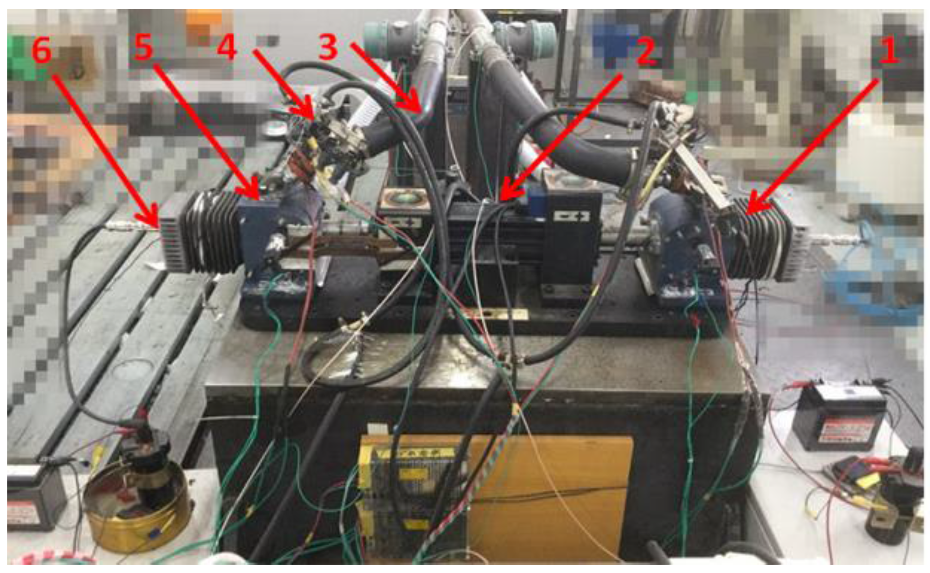
7]. In this paper, the dual piston free-piston engine type was selected because of its higher power-to-weight ratio and the elimination of rebound devices. The schematic diagram of the FPLG prototype is shown in Figure 1. The operating principle of the prototype can be described as follows: combustion occurs alternatively in the two chambers and drives the piston and the connecting rod reciprocating through the linear electric machine (LEM). In this way, the electric current is generated in the LEM’s coils, and part of the chemical energy of the fuel is converted into electricity.
The concept of the free-piston engine was first proposed by Pescara in 1928 [5]. However, the free-piston engine applications including the FPLG underwent a slow development in the early stages and reached stagnation in the 1960s due to the limitations of various factors [8]. In recent years, as an alternative power device for hybrid electric vehicles, the FPLG has attracted increasing interests from worldwide researchers [9]. With the development of the computer control technology, the internal combustion engine technology and material science, significant progress has been made in aspects of the FPLG simulation, experimental techniques, as well as the FPLG control system.
West Virginia University is one of the earliest institutes performing the investigation of modern FPLG system. In [10], the design and construction of a two-stroke dual piston FPLG prototype was provided using spark ignition. Tests were performed to evaluate the performance of the prototype, and the tested output power was 316 W while operating at 23.1 Hz. However, the combustion occurring in the prototype appeared to be extremely unstable, and the machine could not operate continuously. A numerical model was developed [11] that divided the working cycle of the FPLG into three stages according to the piston motion, that is the scavenging process, the compression process and the combustion process. Each process was described by mathematical models in accordance with the laws of thermodynamics. It was synthetically analysed how the total heat input, the combustion duration, the reciprocating mass and the load influenced the operation characteristics of the FPLG, such as the position of the TDC and the frequency and the piston velocity. In 2002, a numerical model of a compression-ignited FPLG was developed [12]. Its bore was 75 mm, and the stroke was 71 mm. The output power and the indicated efficiency for the base case could reach 7.1 kW and 40.86%, respectively. Then, they also examined the effects of translator mass, the premixed to diffusive burn ratio, injection timing and load values on the performance.
Mikalsen and Roskilly at Newcastle University began to investigate FPLG from 2007. The piston dynamics of an FPLG were investigated [13], which indicated that its piston motion was asymmetrical around TDC, and the engine spent more time in the compression than in the expansion phase of the cycle. Then, they carried out simulations using the CFD (computational fluid dynamics) toolkit OpenFOAM on the working process of the FPLG and compared its performance to a conventional engine. The results showed that the performance of the FPLG had a slight advantage over the conventional engine for faster-burning fuels [
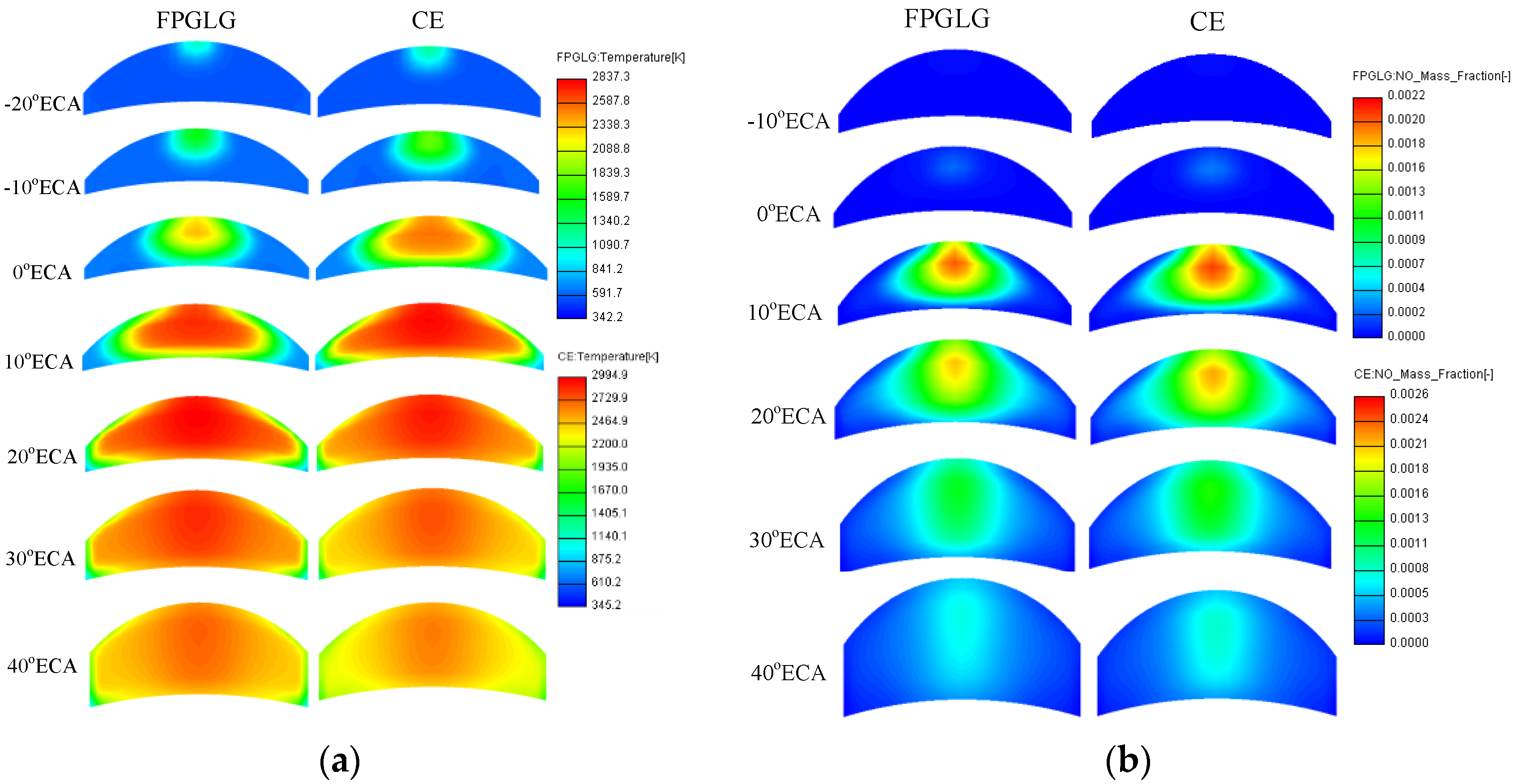
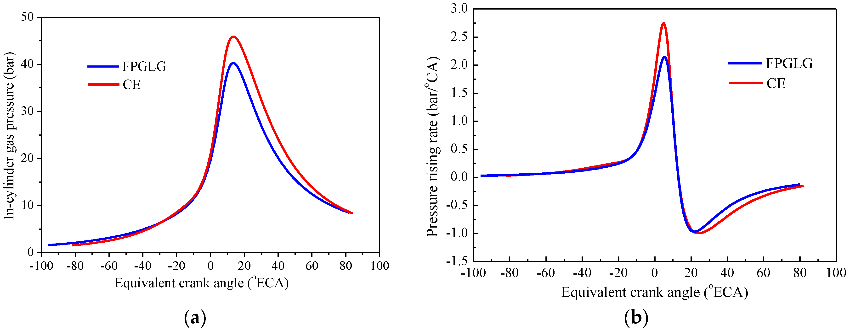
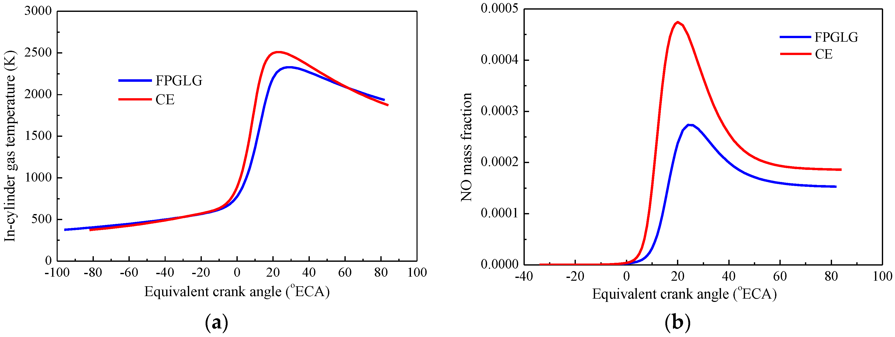
14]. In 2009, a computational study was undertaken to investigate the in-cylinder gas motion, combustion process and nitrogen oxide formation in a diesel FPLG [15]. It was found that the in-cylinder gas temperature in the FPLG was lower than that in the CE, which contributed to the decrease of the NOx emission.
The European Commission promoted a research project about a new energy power plant named FPEC (free piston energy converter) in the year 2002 [8]. The researchers presented the thermodynamic modelling of the FPEC and emphatically analysed the heat release process and its scavenging characteristics by a multi-dimensional simulation method [16,17]. The results indicated that the fuel with a lesser octane number required a higher compression ratio, and the higher compression ratio would increase the operating frequency, power output and efficiency of the system.
Researchers from Beijing Institute of Technology have done studies on the piston motion, the combustion heat release process and the electricity-generating characteristics of the FPLG. They utilized computational modelling and single-step parametric variations to analyse the scavenging system for an FPLG [18]. The results showed that a higher effective stroke length to bore ratio and a long valve overlapping distance with a low supercharge could achieve a good scavenging performance. Professor Feng et al. investigated the combustion process of a diesel FPLG by adopting coupled models of zero-dimensional dynamics and multidimensional computational fluid dynamics [7]. The simulation results revealed the basic combustion characteristics of the FPLG fuelled by diesel. In 2015, Song presented a novel design of a single-cylinder FPLG incorporating a linear motor as a rebound device [19]. Both simulations and experiments were undertaken to investigate the stable generating characteristics, and the results indicated the output power of 25.9 W and the system efficiency of 13.7%. In addition, they have established prototypes that could basically realize continuous fire during the starting process. However, the misfire phenomenon was obvious due to the bad scavenging efficiency.
The research group led by Chang, Siqin at the Nanjing Institute of Technology conducted studies mainly on the control and experiments of a single-cylinder spark-ignited FPLG, which worked on four-stroke cycles. In the aspect of the engine control, the motion state of the free piston was controlled by the electromagnetic force of the linear generator, thus making the FPLG work continuously. As for the prototype, the bore was 62 mm, and the stroke was 70 mm. They tested the prototype during the stable operation process, and the obtained power output and generating efficiency were 2.2 kW and around 34%, respectively [20].
Toyota Central R&D Labs Inc. has published a number of patents and articles about FPLG. The proposed structure featured a hollow circular step-shaped piston and an oil cooling passage for enough cooling ability of the piston. The researchers assessed the spark ignition (SI) combustion and premixed charged compression ignition (PCCI) combustion by performing one-dimensional simulations, and the two cases both obtained an output power of 10 kW [21]. In addition, the control logic of the linear generator was studied, which selected both the position and velocity of the piston as feedback parameters. The proposed feedback method realized stable and robust control behaviour with respect to abnormal combustion conditions, such as pre-ignition [22].
In general, the researchers have conducted both simulations and experiments on the operation principle of the FPLG, as well as the performance of the prototype. As for the combustion process analysis, most reports used zero-dimensional, single-zone models to simulate the working process of the FPLG, which showed a limited accuracy to predict the parameters in the combustion process. Afterwards, with the development of the CFD software, the coupled dynamic-multidimensional model was applied, which could account for the gas flow in the cylinder [
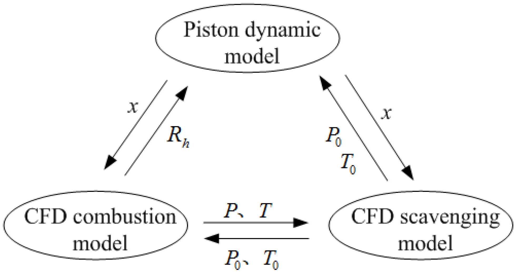
23] and had a higher accuracy to describe the combustion details of the FPLG. However, the scavenging performance was usually ignored in the model, which was supposed to have significant effects on the combustion process for the FPLG. Currently, the method of coupling the dynamic and scavenging models into the combustion process simulation was put forward [
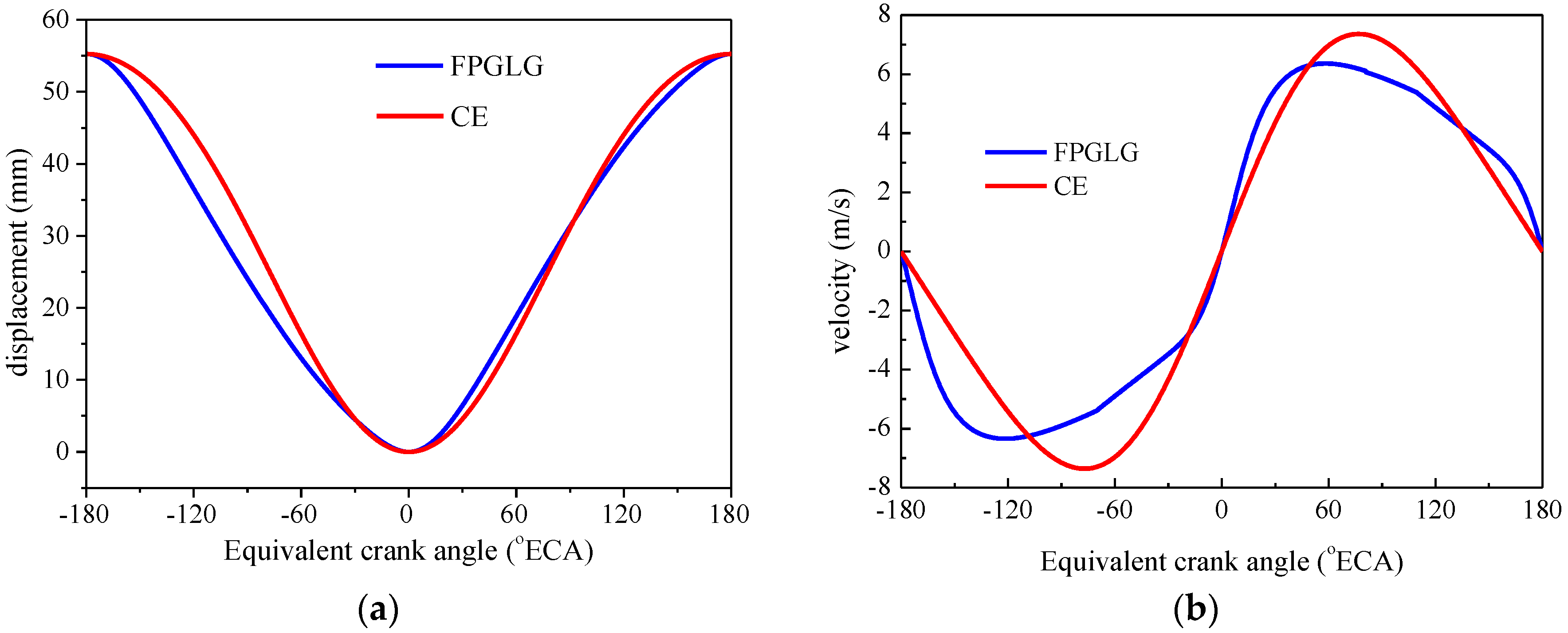
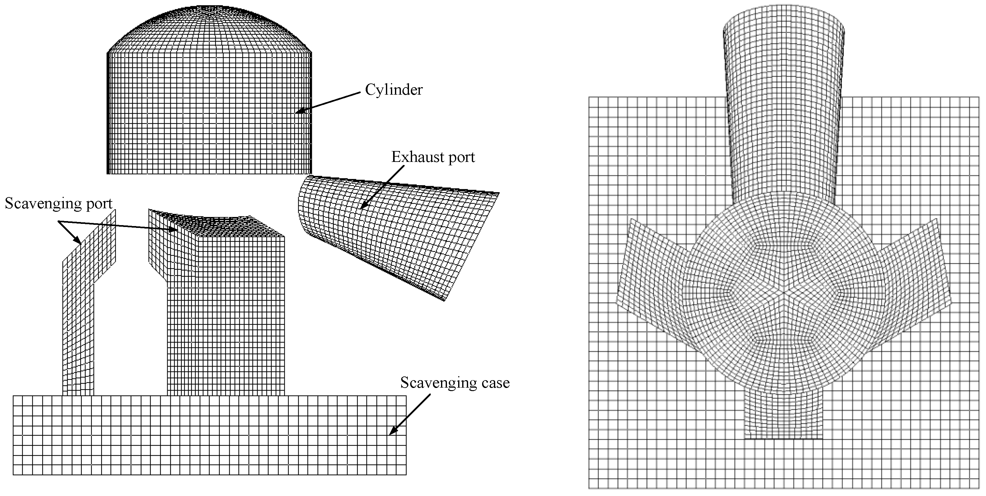
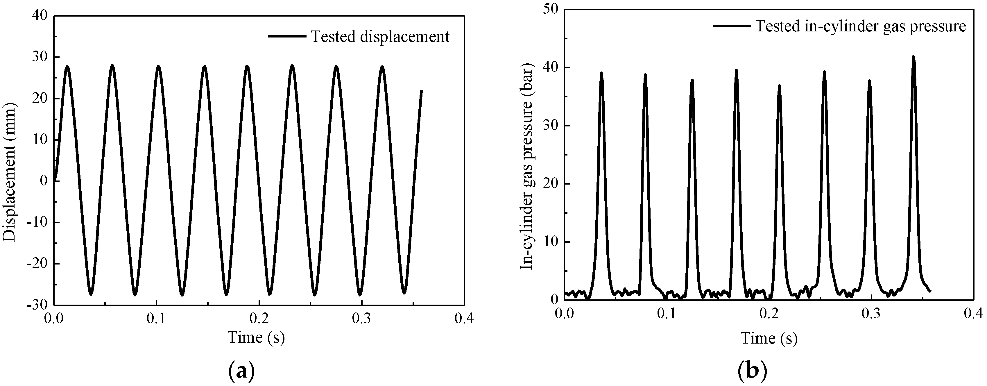
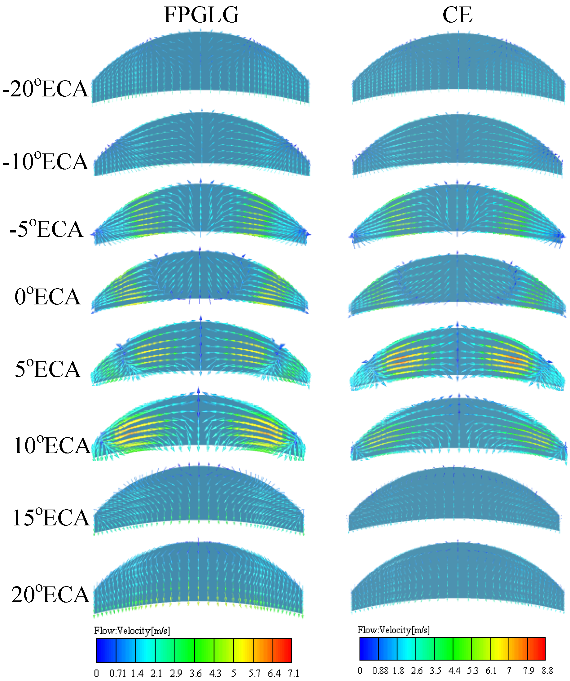
24]; however, few research has been reported on carrying out combustion process analysis by this method on the FPLG fuelled by gasoline. Moreover, few studies have been done focusing on the detailed combustion heat release process of a FPGLG. Therefore, this paper performed the three-dimensional combustion simulation analysis of a FPGLG during the stable generating process by inputting the piston displacement data into the software AVL/Fire. Besides, the three-dimensional scavenging model was coupled into the calculation process in order to obtain the more accurate boundary conditions for the simulation analysis. The results revealed well the real-time combustion characteristics and the heat release characteristics of the FPGLG. Comparisons were made with a conventional internal combustion engine of the same structural parameters.

2. Simulation Methodology

The combustion process calculation of the FPGLG during the stable generating process applied a numerical iterative method, coupling the piston motion features and the CFD scavenging model [24]. The iterative procedure is illustrated in Figure 2.
In Figure 2, x is the piston displacement; R h is the combustion heat release rate; P and T represent the in-cylinder gas pressure and temperature calculated by the CFD combustion model; P 0 and T 0 represent the in-cylinder gas pressure and temperature calculated by the CFD scavenging model. The detailed iterative process can be described as follows:
  • The piston dynamic model of the FPGLG is established based on the second law of thermodynamics and the Wiebe heat release function; the inputs of the model are the gas parameters at the starting position of the compression stroke, and its output is the piston motion profile.
  • According to the piston motion profile, the mesh movement in the CFD combustion model and the CFD scavenging model can be developed.
  • The in-cylinder gas pressure and temperature at the end of the scavenging process from the CFD scavenging model, along with the heat release rate from the CFD combustion model, will be in turn applied to the zero-dimensional piston dynamic model in order to predict the piston motion rule in the next iterative process.
  • The mesh movement and the initial boundary conditions of the CFD combustion model are updated based on the new piston motion data and the calculated in-cylinder gas parameters from the CFD scavenging model.
  • Repeat Steps (3) and (4) until the deviation between the in-cylinder gas pressure results from the 3-dimensional combustion model and the zero-dimensional piston dynamic model was less than 5%.
After performing the numerical iterative process, the accurate CFD combustion model of the FPGLG can be acquired with appropriate boundary conditions.

2.1. Piston Dynamic Model

The movement of the piston assembly is decided by the forces acting on it while the FPGLG is in the stable generating process, as illustrated in Figure 3.
P s l and P s r stand for the gas pressure from the left and right scavenging cases, respectively, which are assumed to be equal as the scavenging pressure in the two scavenging cases keeps the same. Therefore, the dynamic equation of the piston assembly can be derived as below [7,25] according to Newton’s Second Law:
( P l P r ) A F e F f = m d 2 x d t 2
where P l and P r respectively represent the in-cylinder gas force on the top surfaces of the left and right pistons; A is the piston area; F e is the electromagnetic force caused by the load motor; F f is the friction force; m is the mass of the piston assembly; x represents the piston displacement; and t is time.
During the stable generating process, the electromagnetic force F e caused by the load motor has a linear relationship with the piston’s velocity, as illustrated in Equation (2).
F e = C e d x d t
where C e is the electromagnetic damper coefficient of the load motor.
Additionally, the friction force F f in the system can be seen as a constant [26].
In order to predict the in-cylinder gas pressure variation in the combustion chamber of the FPGLG, a thermodynamic equation has been derived, shown as bellow [13]:
d P d t = 1 V ( ( γ 1 ) d Q d t γ P d V d t )
d Q d t = d Q c d t d Q h d t
where P is the in-cylinder gas pressure; γ is the specific heat ratio; V is the cylinder volume; Q c represents the heat released by the burnt fuel; and Q c represents the heat transfer loss.
The zero-dimensional mathematical model to calculate the working process of FPGLG can be established using MATLAB/Simulink by applying the piston dynamic model. The geometric and initial simulation parameters of the FPGLG are shown in Table 1.
The piston dynamic characteristics of the FPGLG are compared to a conventional two-stroke engine virtually established by method of equivalent speed transform [27]. The configuration of the CE is shown as Figure 4; where C is the length of the rod, R is the crank radius and α is the angle between the crank and the axis of the cylinder.
To make it comparable, the two engines must run at the same operation frequency with equal bore and stroke. Additionally, as the software AVL/Fire can only read the piston position data measured in crank angles, the equivalent crank angle (ECA) is adopted to normalize the piston motion in FPGLG transferred from time by Equation (5) [18]. In the study, the piston position at the TDC was defined as 0 °ECA.
ECA = ( t t 0 ) f 360
where t 0 is the start time, t is any time in the running period and f is frequency.
Figure 5 shows the piston dynamic characteristics of the FPGLG and the CE. The displacement curve of the FPGLG is calculated from the zero-dimensional piston dynamic model, and the piston position of the CE at the same crank angle is calculated by Equation (6) when setting the piston displacement as zero at the TDC:
x = R [ ( 1 cos α ) + λ 4 ( 1 cos 2 α ) ]
where λ = C / R , and it is set to be 0.25 in this case.
As can be seen in Figure 5, for the lack of the mechanical restraint of the crank and connecting rod, the piston motion characteristics of FPGLG are distinguished from those of CE. The peak velocity of the FPGLG was smaller, and the acceleration at both the TDC and BDC (bottom dead centre) was much higher. That means, compared to CE, the FPGLG moved more slowly in the compression stroke and moved relatively faster in the expansion stroke. As a result, the piston of the FPGLG had a shorter retention time around the turning points, which would help reduce the NOx emission caused by high temperature.
Analysing the behaviour of the FPGLG under different operating conditions will help us learn more about its dynamic characteristics. Figure 6 shows the piston displacement curves at different external load resistance. The bigger load resistance means smaller current in the LEM, thus leading to the decrease in the electromagnetic resistance. As a result, we can see in Figure 6a that the stroke and the running speed became greater with the increasing external load resistance. Figure 6b demonstrates the normalized piston displacement of the FPGLG, and the displacement curves at different external load resistance presented the same tendency corresponding to the ECA, except for the slight difference in the amplitude. Therefore, with the varying operation conditions, the normalized piston dynamic curves of the FPGLG and the CE will have the same relationship as Figure 5 shows. Additionally, the combustion characteristics influenced by the piston dynamics will also present the same rule. As a result, we only covered one operating point of FPGLG in this paper to investigate the difference in the combustion process of the two engines.

2.2. CFD Combustion Model

The three-dimensional CFD combustion model was established according to the prototype with a hemispherical combustion chamber placed at the bottom of the cylinder head and a dome-type piston. Considering that the effective compression stroke starts after the exhaust port closes, the simulation scope for the combustion process calculation ranged from the exhaust port closing (EPC) to the exhaust port opening (EPO) [18]. Figure 7 shows the computational mesh model developed with the software AVL/Fire. At the beginning of the calculation, the whole domain contained 43,392 cells, including 43,104 hexahedron cells and 288 prism cells.
For the combustion process simulation, there are many mathematical models provided in Fire [28], among which the extended coherent flame model (ECFM) was applied since the FPGLG is a spark-ignited engine with premixed charge. The ECFM has been mainly developed in order to describe combustion in direct ignition spark-ignited engines, and it is also recommended for all types of gasoline and gas engine applications. The model assumes that the reaction takes place within relatively thin layers that separate the fresh unburned gas from the fully-burnt gas [29]. Furthermore, a two-step chemistry mechanism is used taking CO and H2 formation in near stoichiometric and fuel rich conditions into account. Additionally, a decoupled treatment of chemistry and turbulence is also considered in this model.
In the CFD combustion model of the FPGLG, the k-zeta-f sub-model was adopted to describe the turbulent flow in the cylinder, and the extended Zeldovich model was used to calculate the emission of NO. Besides, the momentum equation employed the MINIMOD relaxed scheme for discretization, which was better for stability and convergence than the central differential scheme [30]. The initial simulation parameters of the CFD combustion model are listed in Table 2.

2.3. CFD Scavenging Model

The scavenging process of a two-stroke engine is driven by the reciprocating movement of the piston, which controls the opening and closing of the gas ports. Based on the geometric features, the scavenging model was divided into four regions, namely the cylinder, the scavenging port, the exhaust port and the scavenging case. Each region should be meshed separately, and the final computational mesh model was constructed by combining the four regions together. For the cylinder, its initial meshes were the same as in the combustion model described in Section 2.2. Additionally, the other three regions were all meshed by the hexahedral element type for higher accuracy. In total, there were 86,878 solid cells in the CFD scavenging model, as shown in Figure 8.
The boundary conditions for the scavenging process simulation of the FPGLG are listed in Table 3. As can be seen, the wall temperatures of the calculation domain were set to be constant values, and the inlet and outlet were kept under constant pressure conditions. In addition, the initial in-cylinder gas parameters were obtained from the CFD combustion simulation, which would be updated in the numerical iterative process.

3. Model Validation

3.1. Description of the Test Bench

The test was conducted on the FPGLG prototype shown in Figure 9. The scavenging pressure of the prototype was 1.2 bar, and the external load resistance was 28 Ω. The control system of the prototype consisted of a set of NI (National Instruments) equipment, which included a 2.3-GHz controller and a synchronous data acquisition card with 16 channels. Besides, the open-loop control strategy was used to control the fuel consumption, injection timing and throttle opening of the prototype and programmed by the software LabVIEW (NI, Austin, TX, USA). More details about the prototype development, modelling and experimental results can be found elsewhere [31,32,33,34].
The collected parameters during the test included in-cylinder gas pressure, piston position and the pressure in the scavenging case. The main parameters of the sensors used during the test are listed in Table 4.

3.2. Comparison of the Simulation and Test Results

By carrying out experiments on an FPGLG prototype, variations of piston position and in-cylinder gas pressure were observed. As can be seen in Figure 10, the piston motion profile of the FPGLG was not symmetric. The piston spent more time during the compression stroke than the expansion stroke as reported in several references [7,14]. The collected in-cylinder gas pressure presented fluctuations due to the cyclic variation during the combustion process. Therefore, the comparison was done between the simulated in-cylinder gas pressure and the average tested data.
The data in Figure 11 compare the test results and the simulation results, both of which show the profile of the in-cylinder gas pressure with the ECA. It has been observed that the simulation results and the test results presented a similar tendency, while the tested peak pressure was achieved earlier and was slightly lower than the simulation result. As the changes of the two curves were consistent and the peak error between them was less than 5%, the simulated results could reflect the real-time characteristics of the in-cylinder gas pressure, and the accuracy of the CFD combustion model was acceptable.

4. Simulation Results and Discussion

The combustion process of the FPGLG was compared to the CE. The simulation of the two engines lasted from the EPC to the EPO. As can be seen from Table 5, the FPGLG experienced an ECA course of −100–82 °ECA, and the CE experienced an ECA course of −84–84 °ECA. For engines with premixed charge, the ignition timing has a significant influence on the combustion process. Therefore, both of the engines adopted the same ignition advance position to guarantee the compression ratio at the same ignition time. As shown in Table 5, the ignition advance position of the two engines was 8 mm before the TDC, at which both of them showed good performance in the simulations. Moreover, in order to make the simulation results more comparable, the initial set conditions of the two engines were all identical, such as the intake air pressure and temperature, the equivalence ratio and the turbulence kinetic energy in the cylinder.

4.1. Comparison of the In-Cylinder Gas Flow Characteristics

The in-cylinder gas flow characteristics have an important influence on the combustion process. Figure 12 shows the gas flow field of the FPGLG and the CE. It can be seen that, at the later stage of the compression stroke, the gas flew to the edge space from the middle of the chamber with the piston moving close to the cylinder head, thus forming the squish motion. After climbing over the TDC, the piston moved downwards, and the gas flew back to the middle from the annular edge of the chamber, leading to the reversed squish motion. Both the squish and the reversed squish contributed to enhancing the gas turbulence intensity in the cylinder and, in this way, helped promote the burning rate of the mixture.
There are differences in the gas flow characteristics of the FPGLG and the CE due to their different piston dynamics. It is revealed in Figure 12 that the peak gas flow velocity in the FPGLG was 7.1 m/s, which was lower than that in the CE. The strongest gas flow intensity occurred earlier in the CE, because the piston velocity of the CE was bigger than that of the FPGLG in the late compression stroke. However, in the expansion process, the gas flow intensity of the FPGLG was a little stronger than that of the CE for its faster expansion speed.

4.2. Comparison of the Engine Performance

4.2.1. In-Cylinder Gas Pressure

Figure 13a illustrates the in-cylinder gas pressure changes during the combustion process of the FPGLG and the CE. It can be seen that when the air fuel mixture in the two engines was ignited at the same advance position, the peak in-cylinder gas pressure achieved in-cylinder of the FPGLG was about 5 bar lower than that of the CE. Although the ignition timing of CE was later than that of the FPGLG, the in-cylinder gas pressure of the two engines reached their peak values almost at the same ECA. The changes of the in-cylinder gas pressure rising rate are shown in Figure 13b. It is found that the positive pressure rising rate of the FPGLG was lower than that of the CE, and it also reached the peak value later. After going over the positive peak value, the pressure rising rate of the two engines declined sharply with a similar trend and showed minimal difference in the negative peak values. Despite that, the peak negative pressure rising rate of the FPGLG was still lower than that of the CE. In general, compared to the CE, the FPGLG operated in a more moderate way and showed a lower possibility of deflagration or engine knocking, due to the lower in-cylinder gas pressure and pressure rising rate.

4.2.2. Indicated Thermal Efficiency

Figure 14 displays the pressure-volume diagrams of the FPGLG and the CE. It is obvious that the heat release process of the CE was closer to an isochoric process than that of the FPGLG. Besides, more indicated work was done by the CE because of its higher in-cylinder gas pressure in the power stroke. Although the faster expansion process led to less heat transfer loss in the FPGLG, its simulated indicated thermal efficiency was still lower than that of the CE at the operation point covered in this paper. However, the results only presented a small difference as the indicated thermal efficiency of the FPGLG was 30.66% and that of the CE was 31.84%.

4.2.3. NO Emission

The extended Zeldovich model was used in the study to estimate the NO formation. The reaction mechanism of this model is expressed below [14]:
N 2 + O NO + N
N + O 2 N O + O
N + O H N O + H
This reaction mechanism considers the effect of oxygen, nitrogen and hydrogen radicals on NO formation, and all of the three chemical reactions have been proven to exhibit strong temperature dependency.
Figure 15 illustrates the in-cylinder gas temperature field and the NO formation field at varied equivalent crank angles. It is obviously seen in Figure 15a that the high temperature occurred with the chemical reactions and spread to the whole chamber with the flame propagation. The highest local temperature in the FPGLG was 2837.3 K, while the highest local temperature in the CE reached 2994.9 K. Besides, at the same angle, the distribution space of the high temperature in the CE was larger than in the FPGLG. From Figure 15b, we can see that the NO was produced mainly within the 20 °ECA after TDC. Additionally, the NO mass friction became less at the end of the combustion process because of the decreasing temperature. However, on the whole, the NO formation level was lower in the FPGLG than in the CE.
The changes of the mean in-cylinder gas temperature are shown in Figure 16a. As can be seen, when the FPGLG and the CE ignited at the same advance position, the mean in-cylinder gas temperature of the FPGLG was slightly lower than that of the CE, and the difference on the peak value was 182.3 K. The results were mainly influenced by the shorter retention time of the FPGLG’s piston around the TDC. Figure 16b illustrates the changes of the NO mass fraction in the whole cylinder during the combustion process. This indicates that the NO produced in the FPGLG was much less and the peak value of the NO mass fraction in the FPGLG was just half of that in the CE. After the combustion process, the remaining NO mass fraction in the FPGLG was 0.000152, while that in the CE was 0.000186. Therefore, the FPGLG has an obvious advantage in terms of NO emission over the CE because of its lower in-cylinder gas temperature during the combustion process.

4.3. Comparison of the Heat Release Characteristics

Figure 17 separately shows the heat release rate and the accumulated heat release results during the combustion process of the two engines. It can be found that the heat release process of the FPGLG lasted for a longer time than that of the CE. The peak heat release rate of the FPGLG was lower, and it also arrived later compared to that of the CE. For the CE, most of the fuel was burnt up within the 20 °ECA after the TDC with a shorter post-combustion period; while in the FPGLG, less heat was released around the TDC, and its post-combustion developed in a slower rate.
The combustion process of the FPGLG and the CE is compared in Figure 18, in which the side colour bar indicates the mass fraction of the residual gasoline in the combustion chamber. As can be seen, the combustion in the FPGLG started earlier because of its earlier ignition timing. However, the slower compression speed before the TDC led to the FPGLG having weaker in-cylinder gas flow intensity than the CE, and as consequence of this, the flame propagation velocity in the FPGLG was slower. Especially after the TDC, the combustion chamber’ volume of the FPGLG enlarged quickly due to its bigger expansion speed than that of the CE, causing it to take a longer distance and time for the flame to spread to the unburned mixture. Therefore, compared to the CE, the FPGLG possessed a longer heat release process when the two engines employed the same ignition advance position.

4.4. Comparison of the Combustion Duration Characteristics

The total combustion duration is defined from the ECA when the accumulated heat release exceeds zero to the ECA when the accumulated heat release gets up to 97% of the whole heat release. As shown in Figure 19, the combustion process of the FPGLG can be divided into three stages, namely the ignition delay period, the rapid combustion period and the post-combustion period. The ignition delay period (a–b) starts with the flashover of the spark plug and ends up with the separation of the ignition curve with the compression curve. The rapid combustion period (b–c) is from the end of the ignition delay period to the peak in-cylinder gas pressure point. Additionally, the post-combustion period (c–d) goes through the end of the rapid combustion period to the end of the total combustion duration.
Table 6 indicates the combustion duration comparison of the FPGLG and the CE. When the two engines adopted the same ignition advance position, it is found that the combustion duration of the CE was 63.0 °ECA, and the combustion duration of the FPGLG was 76.7 °ECA.
The different stages’ comparison during the combustion process of the FPGLG and CE is demonstrated in Figure 20. From the point of the combustion stage duration, the ignition delay period of the FPGLG and the CE had little difference. The reason was that they both worked in the way of premixed combustion, so the mixing condition of the oil and the fresh air was hardly influenced by the piston motion. In addition, at the ignition timing, the in-cylinder gas pressure and temperature of the two engines had presented little difference. During the rapid combustion period, the flame developed rapidly, and more heat was released, leading to the in-cylinder gas pressure of the FPGLG and CE rising fast and getting to the peak at around 15 °ECA after the TDC. Although the peak in-cylinder gas pressure values of the two engines had a great difference, their appearance time was nearly the same. The main distinction of the combustion duration between the FPGLG and CE was in the post-combustion period. In this combustion stage, the piston of the FPGLG moved to the BDC rapidly and slowed down the flame propagation speed. As a result, it would take a longer time for the remaining fuel to be burnt up in the FPGLG. Therefore, it can be seen in Figure 20 that the continuous ECA that the FPGLG occupied in the post-combustion period was two-times what the CE did.
From the point of the percentage that each of the combustion stage occupied in the whole duration, the rapid combustion period of the CE took up approximately half of the whole combustion duration, while that of the FPGLG took up a lower percentage as 44.6%. The proportion of the post-combustion period held by the FPGLG was 25.0%, which was much more than that of the CE did. This also indicated that the FPGLG had a serious afterburning problem. As for the ignition delay period, the two engines occupied a similar percentage in the whole combustion duration.

5. Conclusions

In this work, the numerical iterative method was used to calculate the combustion process under the stable generating condition in the FPGLG, coupling the piston dynamic model and the CFD scavenging model. The combustion characteristics of the FPGLG were investigated emphatically, and the main findings are drawn as below:
  • Compared to the CE, the peak velocity of the FPGLG was lower, and it featured larger accelerations around both the TDC and the BDC; the FPGLG had a slower compression stroke and a relatively quicker expansion stroke than CE, as a result of which, its piston stayed for a shorter time around the turning points.
  • Compared to the CE, the peak gas flow velocity in the FPGLG was lower, and the strongest gas flow intensity occurred later. The gas flow intensity of the FPGLG in the expansion stroke was a little stronger than that of the CE for its faster expansion speed.
  • Compared to the CE, the in-cylinder gas pressure and the pressure rising rate of the FPGLG were lower, which made it work in a more gentle way and presented a smaller tendency of deflagration; the combustion in the FPGLG was less close to an isochoric process, and its slightly lower indicated thermal efficiency was observed at the operation point covered in this paper; when the two engines adopted the same ignition advance position, the mean in-cylinder gas temperature of the FPGLG was lower, which contributed to declining of the formation of the pollutant NO.
  • Compared to the CE, the combustion heat release process of the FPGLG lasted for a longer time; less heat was released around the TDC in the FPGLG due to the piston motion rule of slower compression and quicker expansion; the peak heat release rate of the FPGLG was found to be lower than that of the CE.
  • The ignition delay duration of the FPGLG and the CE presented little difference because of the two engines working in the same way of premixed combustion; the rapid combustion period of the FPGLG took up a smaller percentage in its whole combustion process than that of the CE did; but the main distinction of the two engines laid in the post-combustion period, which for the FPGLG and the CE, respectively, occupied the proportions of 25.0% and 15.4%; by comparison, the serious afterburning problem in the FPGLG was found and remained to be solved.

Acknowledgments

This work was sponsored by the National Natural Science Foundation of China (Grant No. 51006010) and a joint China-UK research programme “111” (B12022). We would like to thank the sponsors.

Author Contributions

Yuxi Miao and Zhengxing Zuo conceived of and established the simulation models. Chendong Guo and Yuyao Guo performed the experiments. Huihua Feng analysed the data. Yu Song contributed analysis tools. Yuxi Miao wrote the paper. Chendong Guo and Boru Jia helped revise the paper.

Conflicts of Interest

The authors declare no conflict of interest.

Abbreviations

The following abbreviations are used in this manuscript:
FPGLGFree-piston gasoline engine linear generator
CEConventional engine
TDCTop dead centre
FPLGFree-piston linear generator
LEMLinear electric machine
CFDComputational fluid dynamics
FPECFree piston energy converter
SISpark ignition combustion
PCCIPremixed charged compression ignition combustion
ECAEquivalent crank angle
BDCBottom dead centre
EPCExhaust port closing
EPOExhaust port opening
ECFMExtended coherent flame model
NINational Instruments

References

  1. Sun, Y.L.; Zhuang, G.S.; Tang, A.H.; Wang, Y.; An, Z.S. Chemical Characteristics of PM2.5 and PM10 in Haze-Fog Episodes in Beijing. Environ. Sci. Technol. 2006, 40, 3148–3155. [Google Scholar] [CrossRef] [PubMed]
  2. He, S.; Du, B.; Feng, L.; Fu, Y.; Gui, J.; Long, W. A numerical study on combustion and emission characteristics of a medium-speed diesel engine using in-cylinder cleaning technologies. Energies 2015, 8, 4118–4137. [Google Scholar] [CrossRef]
  3. Ge, J.C.; Kim, M.S.; Yoon, S.K.; Choi, N.J. Effects of pilot injection timing and EGR on combustion performance and exhaust emissions in a common rail diesel engine fueled with a canola oil biodiesel-diesel blend. Energies 2015, 8, 7312–7325. [Google Scholar] [CrossRef]
  4. Peter, A.J.A.; Johan, P.J.; van den, O.; Potma, J.; Vael, G.E.M. Horsepower with brains: The design of the chiron free piston engine. SAE Tech. Paper 2000. [Google Scholar] [CrossRef]
  5. Mikalsen, R.; Roskilly, A.P. A review of free-piston engine history and applications. Appl. Ther. Eng. 2007, 27, 2339–2352. [Google Scholar] [CrossRef]
  6. Goertz, M.; Peng, L. Free piston engine its application and optimization. SAE Tech. Paper 2000. [Google Scholar] [CrossRef]
  7. Feng, H.; Guo, C.; Yuan, C.; Guo, Y.; Zuo, Z.; Roskilly, A.P.; Jia, B. Research on combustion process of a free piston diesel linear generator. Appl. Energy 2016, 161, 395–403. [Google Scholar] [CrossRef]
  8. Mao, J. Numerical Simulation and Experimental Analysis of the Working Process in Free-Piston Linear Generator; Beijing Institute of Technology: Beijing, China, 2011. [Google Scholar]
  9. Hanipah, M.R.; Mikalsen, R.; Roskilly, A.P. Recent commercial free-piston engine developments for automotive applications. Appl. Ther. Eng. 2015, 75, 493–503. [Google Scholar] [CrossRef]
  10. Famouri, P.; Cawthorne, W.R.; Clark, N.; Atkinson, C.; Atkinson, R.; McDaniel, T.; Petreanu, S. Design and Testing of a Novel Linear Alternator and Engine System for Remote Electrical Power Generation. In Proceedings of the IEEE Power Engineering Society 1999 Winter Meeting, New York, NY, USA, 31 January–4 February 1999; pp. 108–112.
  11. Atkinson, C.M.; Petreanu, S.; Clark, N.N. Numerical simulation of a two-stroke linear engine. SAE Tech. Paper 1999. [Google Scholar] [CrossRef]
  12. Shoukry, E.; Taylor, S.; Clark, N.; Famouri, P. Numerical simulation for parametric study of a two-stroke direct injection linear engine. SAE Tech. Paper 2002. [Google Scholar] [CrossRef]
  13. Mikalsen, R.; Roskilly, A.P. The design and simulation of a two-stroke free-piston compression ignition engine for electrical power generation. Appl. Ther. Eng. 2008, 28, 589–600. [Google Scholar] [CrossRef]
  14. Mikalsen, R.; Roskilly, A.P. Performance simulation of a spark ignited free-piston engine generator. Appl. Ther. Eng. 2008, 28, 1726–1733. [Google Scholar] [CrossRef]
  15. Mikalsen, R.; Roskilly, A.P. A computational study of free-piston diesel engine combustion. Appl. Energy 2009, 86, 1136–1143. [Google Scholar] [CrossRef]
  16. Fredriksson, J.; Denbratt, I. Simulation of a two stroke free piston engine. SAE Tech. Paper 2004. [Google Scholar] [CrossRef]
  17. Bergman, M.; Fredriksson, J.; Golovitchev, V.I. CFD-based optimization of diesel-fueled free piston engine prototype for conventional and HCCI combustion. SAE Int. J. Engines 2009, 1, 1118–1143. [Google Scholar] [CrossRef]
  18. Mao, J.; Zuo, Z.; Li, W.; Feng, H. Multi-dimensional scavenging analysis of a free-piston linear alternator based on numerical simulation. Appl. Energy 2011, 88, 1140–1152. [Google Scholar] [CrossRef]
  19. Feng, H.; Song, Y.; Zuo, Z.; Shang, J.; Wang, Y.; Roskilly, A.P. Stable Operation and Electricity Generating Characteristics of a Single-Cylinder Free Piston Engine Linear Generator: Simulation and Experiments. Energies 2015, 8, 765–785. [Google Scholar] [CrossRef]
  20. Xu, Z.; Chang, S. Prototype testing and analysis of a novel internal combustion linear generator integrated power system. Appl. Energy 2010, 87, 1342–1348. [Google Scholar] [CrossRef]
  21. Kosaka, H.; Akita, T.; Moriya, K.; Goto, S. Development of free piston engine linear generator system part 1—Investigation of fundamental characteristics. SAE Tech. Paper 2014. [Google Scholar] [CrossRef]
  22. Goto, S.; Moriya, K.; Kosaka, H.; Akita, T. Development of free piston engine linear generator system part 2—Investigation of control system for generator. SAE Tech. Paper 2014. [Google Scholar] [CrossRef]
  23. Mikalsen, R.; Roskilly, A.P. Coupled dynamic-multidimensional modeling of free-piston engine combustion. Appl. Energy 2009, 86, 89–95. [Google Scholar] [CrossRef]
  24. Yuan, C.; Feng, H.; He, Y.; Xu, J. Combustion characteristics analysis of a free-piston engine generator coupling with dynamic and scavenging. Energy 2016, 102, 637–649. [Google Scholar] [CrossRef]
  25. Jia, B.; Zuo, Z.; Tian, G.; Feng, H.; Roskilly, A.P. Development and validation of a free-piston engine generator numerical model. Energy Convers. Manag. 2015, 91, 333–341. [Google Scholar] [CrossRef]
  26. Xiao, J.; Li, Q.; Huang, Z. Motion characteristic of a free piston linear engine. Appl. Energy 2010, 87, 1288–1294. [Google Scholar] [CrossRef]
  27. Li, L. Study on the in-Cylinder Flow Characteristics and Associated Design Technology of Diesel FPLA; Beijing Institute of Technology: Beijing, China, 2014. [Google Scholar]
  28. Shi, C.; Qin, D.; Tang, Q.; Tian, X. Developments in combustion modeling in ICE. Trans. Chin. Soc. Agric. Mach. 2007, 4, 81–186. [Google Scholar]
  29. Colin, O.; Benkenida, A.; Angelberger, C. 3D modeling of mixing, ignition and combustion phenomena in highly stratified gasoline engines. Oil Gas Sci. Technol. 2003, 58, 47–62. [Google Scholar] [CrossRef]
  30. Fontana, G.; Galloni, E.; Palmaccio, R.; Torella, E. Numerical and experimental analysis of different combustion chambers for a small spark-ignition engine. SAE Tech. Paper 2004. [Google Scholar] [CrossRef]
  31. Jia, B.; Zuo, Z.; Feng, H.; Tian, G.; Roskilly, A.P. Development approach of a spark-ignited free-piston engine generator. SAE Tech. Paper 2014. [Google Scholar] [CrossRef]
  32. Jia, B.; Tian, G.; Feng, H.; Zuo, Z.; Roskilly, A.P. An experimental investigation into the starting process of free-piston engine generator. Appl. Energy 2015, 157, 798–804. [Google Scholar] [CrossRef]
  33. Jia, B.; Zuo, Z.; Feng, H.; Tian, G.; Smallbone, A.; Roskilly, A.P. Effect of closed-loop controlled resonance based mechanism to start free piston engine generator: Simulation and test results. Appl. Energy 2016, 164, 532–539. [Google Scholar] [CrossRef]
  34. Jia, B.; Zuo, Z.; Feng, H.; Tian, G.; Roskilly, A.P. Investigation of the starting process of free-piston engine generator by mechanical resonance. Energy Proced. 2014, 61, 572–577. [Google Scholar] [CrossRef]
Figure 1. The structure of the FPLG prototype. 1. Spark plug; 2. Piston; 3. Cylinder; 4. Fuel injector; 5. External Load; 6. Air-intake tube; 7. Scavenging port; 8. Exhaust port; 9. Stator; 10. Connecting rod.
Energies 09 00655 g001
Figure 2. The numerical iterative method for FPGLG combustion process calculation.
Energies 09 00655 g002
Figure 3. Forces acting on the piston assembly of the FPGLG.
Energies 09 00655 g003
Figure 4. The configuration of the conventional engine.
Energies 09 00655 g004
Figure 5. (a) The piston displacement curves of the FPGLG and the CE; (b) The piston velocity curves of the FPGLG and the CE.
Energies 09 00655 g005
Figure 6. (a) The piston displacement at different external load resistance corresponding to time; (b) the piston displacement at different external load resistance corresponding to the ECA.
Energies 09 00655 g006
Figure 7. Computational mesh for the CFD combustion model.
Energies 09 00655 g007
Figure 8. Computational mesh for the CFD scavenging model.
Energies 09 00655 g008
Figure 9. The physical prototype of the FPGLG. 1. The cylinder; 2. The LEM; 3. Air-intake system; 4. Fuel injection system; 5. Scavenging case; 6. Ignition system.
Energies 09 00655 g009
Figure 10. (a) The tested piston position results; (b) the tested in-cylinder gas pressure results.
Energies 09 00655 g010
Figure 11. Comparison of the simulated and tested in-cylinder gas pressure.
Energies 09 00655 g011
Figure 12. The in-cylinder gas flow field of the FPGLG and the CE.
Energies 09 00655 g012
Figure 13. (a) Comparison of the in-cylinder gas pressure; (b) comparison of the in-cylinder gas pressure rising rate.
Energies 09 00655 g013
Figure 14. Pressure-volume diagram.
Energies 09 00655 g014
Figure 15. (a) Comparison of the temperature field; (b) comparison of the NO formation field.
Energies 09 00655 g015
Figure 16. (a) Comparison of the mean in-cylinder gas temperature; (b) comparison of the in-cylinder NO mass fraction.
Energies 09 00655 g016
Figure 17. (a) Comparison of the heat release rate; (b) comparison of the accumulated heat release.
Energies 09 00655 g017
Figure 18. Combustion process comparison of the FPGLG and CE.
Energies 09 00655 g018
Figure 19. Combustion stage division of the FPGLG.
Energies 09 00655 g019
Figure 20. Different combustion stages’ comparison of the FPGLG and CE.
Energies 09 00655 g020
Table 1. The geometric and initial simulation parameters of the FPGLG.
ParametersValue
Bore (mm)52.0
Effective stroke (mm)28.0
Total stroke (mm)58.0
Exhaust port height (mm)15.0
Scavenging port height (mm)13.5
Compression ratio5.2
Piston and connecting rod mass (kg)5.0
Thrust force constant (N/A)74.4
Coil resistance (Ω)14.0
External load resistance (Ω)28.0
Table 2. The initial simulation parameters of the CFD combustion model.
ParametersValue
In-cylinder gas pressure (bar)1.5
In-cylinder gas temperature (K)370.0
Turbulence kinetic energy17.9
Equivalence ratio1.2
Ignition timing (°ECA)−43.5
Table 3. The initial boundary conditions of the CFD scavenging model.
ParametersValue
Intake air pressure (bar)1.2
Exhaust air pressure (bar)1.0
Wall temperature of the head (K)520.0
Wall temperature of the piston (K)520.0
Wall temperature of the liner (K)500.0
Wall temperature of the scavenging port (K)320.0
Wall temperature of the exhaust port (K)450.0
Table 4. Main technical parameters of the sensors.
SensorsTypeMeasurement Range
Cylinder pressure sensorKistler6052C0–25 MPa
Charge amplifierKistler5064B11-
Displacement sensorWithin the LEM0–150 mm
Scavenging case pressure sensorMeas M5165-00005-005BG0–0.5 MPa
Table 5. Simulation parameters in the CFD combustion model of the FPGLG and CE.
ParametersFPGLGCE
EPC (°ECA)−100.0−84.0
EPO (°ECA)82.084.0
Ignition timing (°ECA)−43.5−40.3
Ignition advance position (mm)8.08.0
Table 6. Combustion duration comparison of the FPGLG and CE.
ParametersFPGLGCE
Ignition timing (°ECA)−43.5−40.3
Combustion starting angle (°ECA)−20.2−19.0
Peak pressure angle (°ECA)14.013.0
Combustion ending angle (°ECA)33.222.7

