3.1. Evaluation of TiO2-Polymer, Surface-Deactivated TiO2-Polymer and ZrO2-Polymer Composite Films
In order to observe the photocatalytic effect of TiO
2-P film when used for ARC purposes, reflectance analyses were carried out. Special attention was paid to the effect of UV light on short wavelengths and to the long run stability analysis of the TiO
2-P film.
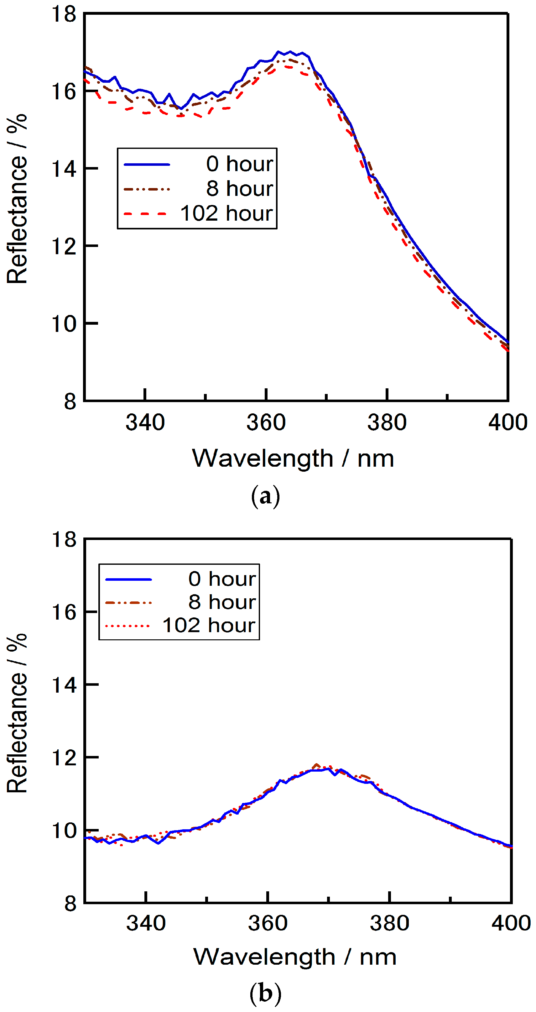
Figure 3 shows the reflectance spectra of the silicon wafers coated with TiO
2-P, ZrO
2-P films or SD-TiO
2-P composite films on short wavelengths. Considerable differences were observed on the short wavelength between the reflectance data of each material. Reflectance was measured from 320 nm to 400 nm initially and after 8 h and 102 h from the first measurement. It was observed that the reflectance of the wafers coated with TiO
2-P coated substrate was increased in the short wavelength by the increase of the illuminating time. This increment of reflectance performance by time in shorter wavelengths can be due to the photocatalytic effect of TiO
2. This increment could be eliminated by SD-TiO
2-P in which the surface TiO
2 nanoparticles are deactivated, and then, the decomposition of organic materials under the UV light could be avoided. No significant change of the reflectance was observed on SD-TiO
2-P and ZrO
2-P coated wafers. These results are important to realize the adverse effect of photo catalysis when using TiO
2 films as an ARC. The photo catalysis effect of TiO
2 becomes rather valuable when the use of it considered for low bandgap and multi junction solar cells that the improved absorbance in UV region of the spectrum is important.
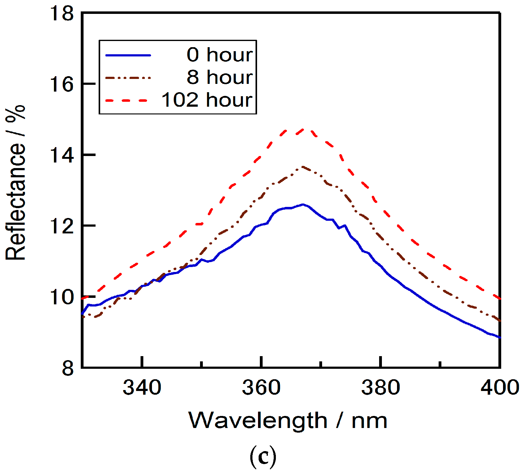
On the other hand, the stability of a film under the continuous illumination is needed to be considered when it was aimed to be used for ARC purposes. The time dependence on the average reflectance of the TiO
2-P, ZrO
2-P and SD-TiO
2-P films on silicon substrates were carried out by continually illuminating the films up to 102 h (under constant light illumination, 1 sun, AM 1.5). Dependence of reflectance of each ARC film to the light irradiation time is given in
Figure 4 (dots show the measurement values, straight and dotted lines show the fitting for easy understanding). SD-TiO
2-P and ZrO
2-P composite films were relatively stable against light irradiation, with average reflectance of around 7% and 6.5%, respectively. However, the reflectance of TiO
2-P coated wafer increased with the irradiation time and the increase is more significant after 10 h of irradiation.
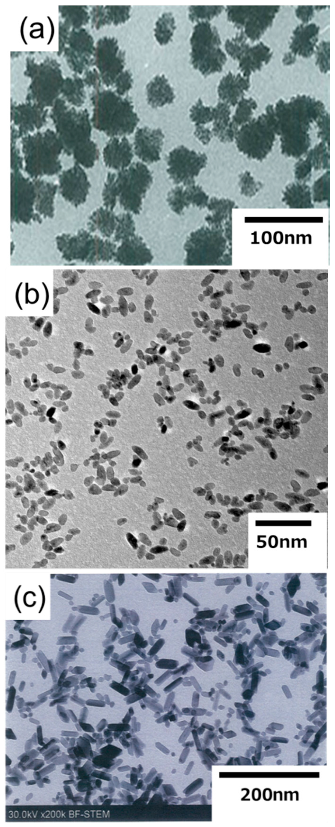
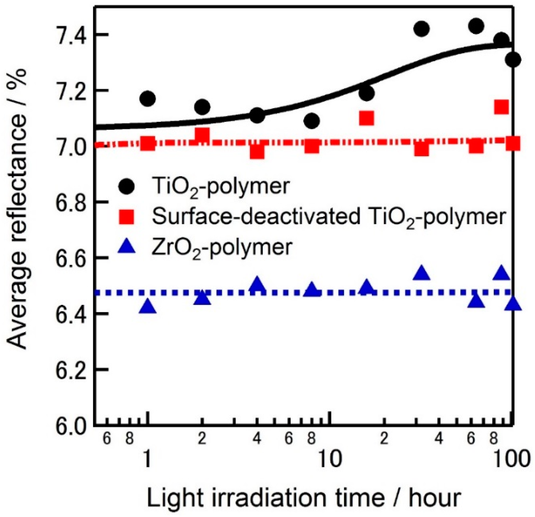
After the confirmation of the photocatalytic effect of TiO2-P film, we focused on the SD-TiO2-P and ZrO2-P films as ARC layers for silicon solar cells. First, zirconium bare solution was spun on the surface of the textured wafer without any additives with spin speed of 4000 rpm for 20 s (acceleration time is 4 s).
Detrimental cracks were observed between the textured pyramids after drying, as shown in
Figure 5a. To avoid these cracks, a mixed solution was prepared with ethanol (1:1 in volume). However, cracks were could not be avoided totally.
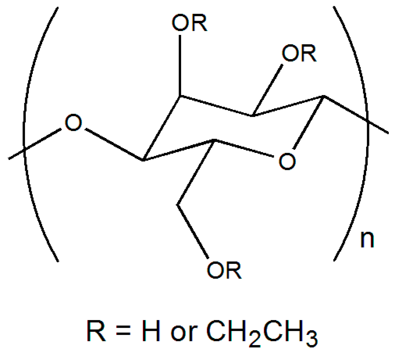
In order to achieve a smooth surface without any cracks, ethyl cellulose was added into the bare zirconium solution. Ethyl cellulose is a non-toxic polymer with good mechanical, physical and chemical properties, including high flexibility, high resistance to moisture and excellent elasticity, which makes it a quality film former [
23]. Moreover, it dissolves in a wide range of solvents and alcohols, which is important for our solution that contains ethanol [
23]. The ratio of ethyl cellulose solution, ethanol and zirconium solution was 1:32:2 (by volume). Spin coating of the latter solution was carried out with similar parameters. Crack-free and smooth surface could be confirmed as shown in
Figure 5b (this is the final solution for ZrO
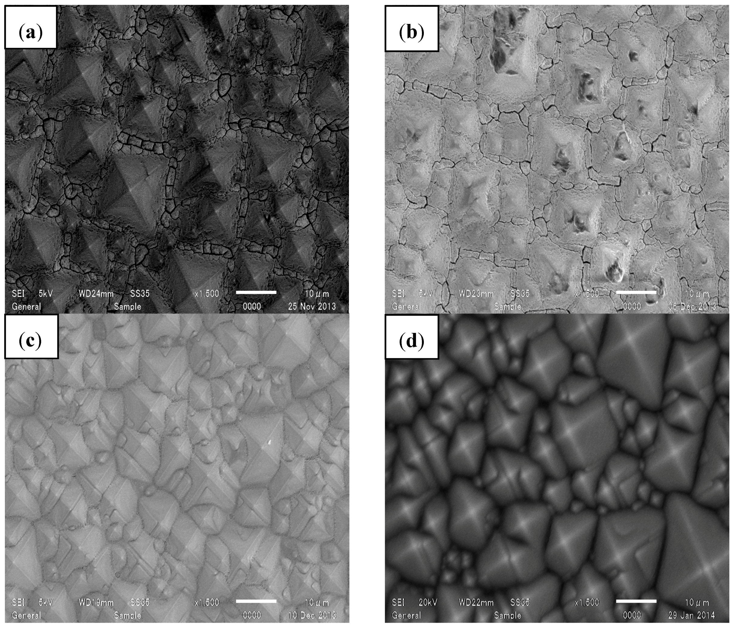
2-P composite film that is used in subsequent experiments). Eliminating the cracks can be attributed to the flexibility and the strength added by ethyl cellulose in the solution. It is also worth mentioning that the good light permeability of the ethyl cellulose makes it an appropriate material to utilize such a solution aimed to be used for ARC material where the transparency is so important. Similarly, surface-deactivated TiO
2 solution was spun on the surface of the textured wafer with a various composition of TiO
2 solution and ethanol and surface condition of the wafers was examined. 1 mL TiO
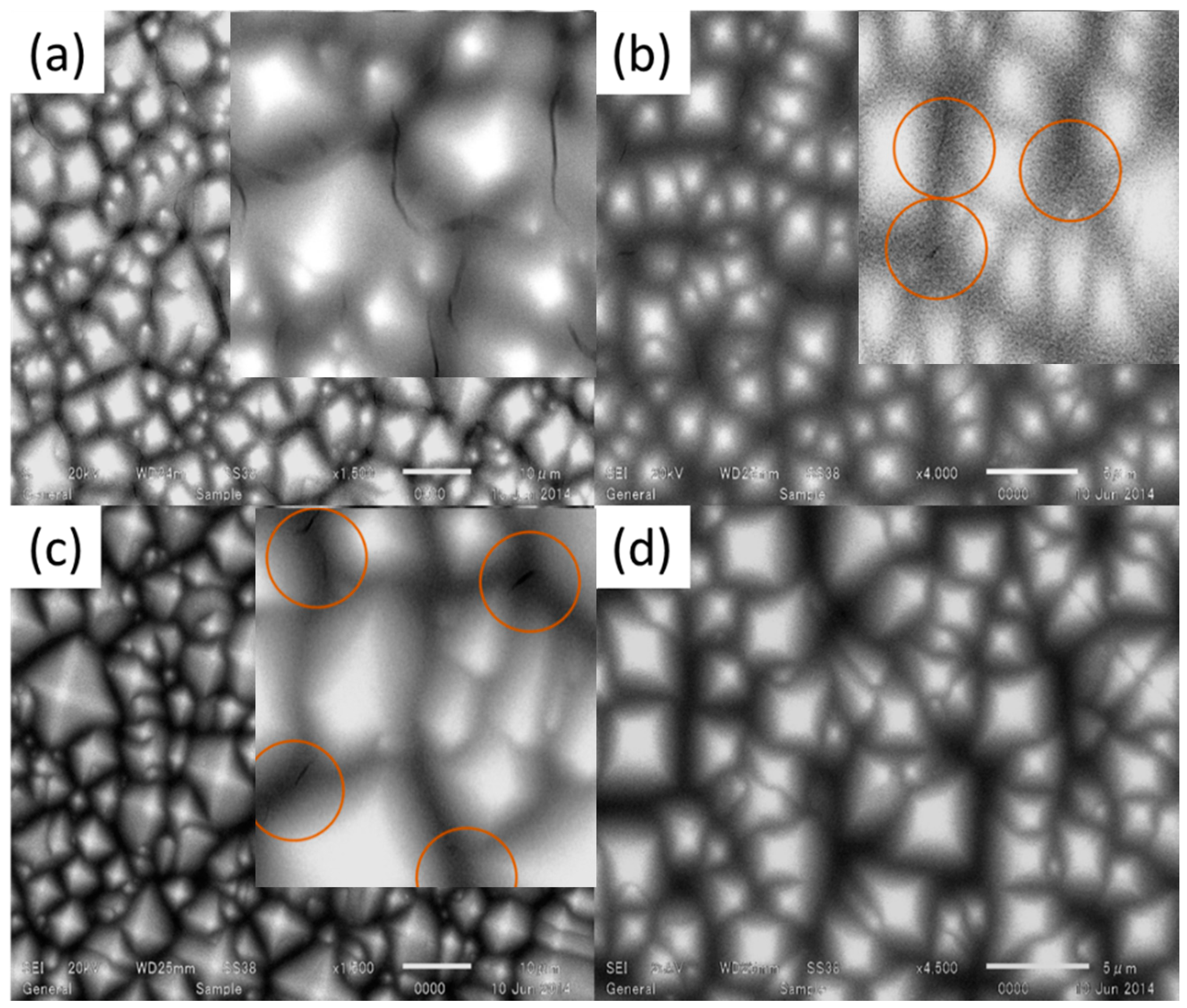
2 solution mixed with 2, 4, 6 or 8 mL ethanol and spun on the textured silicon wafer with spin speed of 5000 rpm for 25 s (acceleration time is 5 s), as shown in
Figure 6a–d. Cracks were observed between the pyramids when the TiO
2 solution was mixed with 2, 4 or 6 mL of ethanol. Surface condition and cracks can be confirmed in the corresponding enlarged images embedded in
Figure 6a–c. Fortunately, TiO
2 solution mixed with 8 mL of ethanol combination provided crack-free surface.
For the initial evaluations of the ZrO
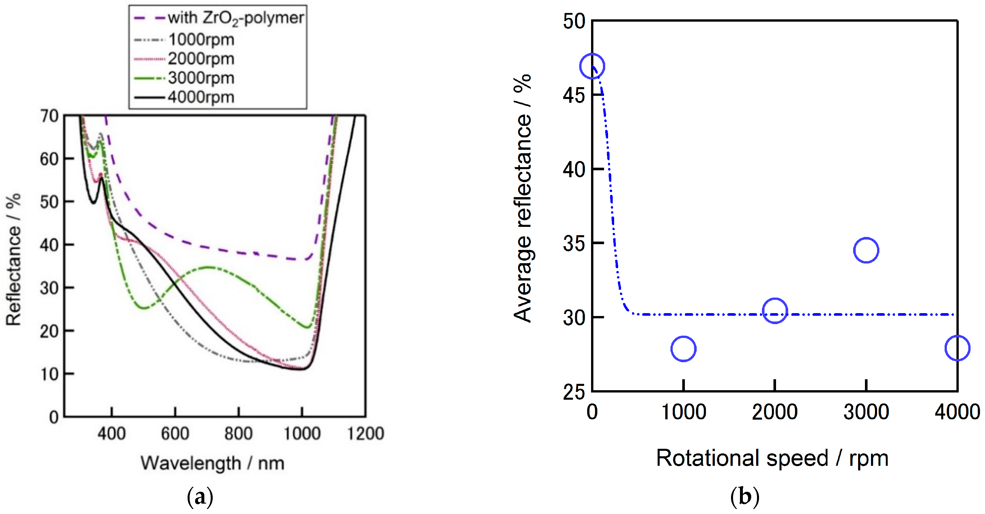
2-P films, it was deposited on flat silicon substrate by a spin-on coating method with a spin-speed in a range from 1000 to 4000 rpm for 20 s (acceleration time is 4 s).
Figure 7a compares the reflectivity of flat silicon substrates w/ and w/o ZrO
2-P layer coated on the surface. The lowest average reflectance (the reflectance average between the wavelength of 300 nm–1100 nm) of 28% was achieved by ZrO
2 coating with a spin speed of 1000 rpm (
Figure 7b), a steady reflectance tendency from wavelength of around 700 to 1000 nm can also be confirmed. Comparing these results it can be confirmed that the average reflectance of a silicon substrate decreased from 40% down to 28% owing to the formed ZrO
2 film on the flat silicon surface.
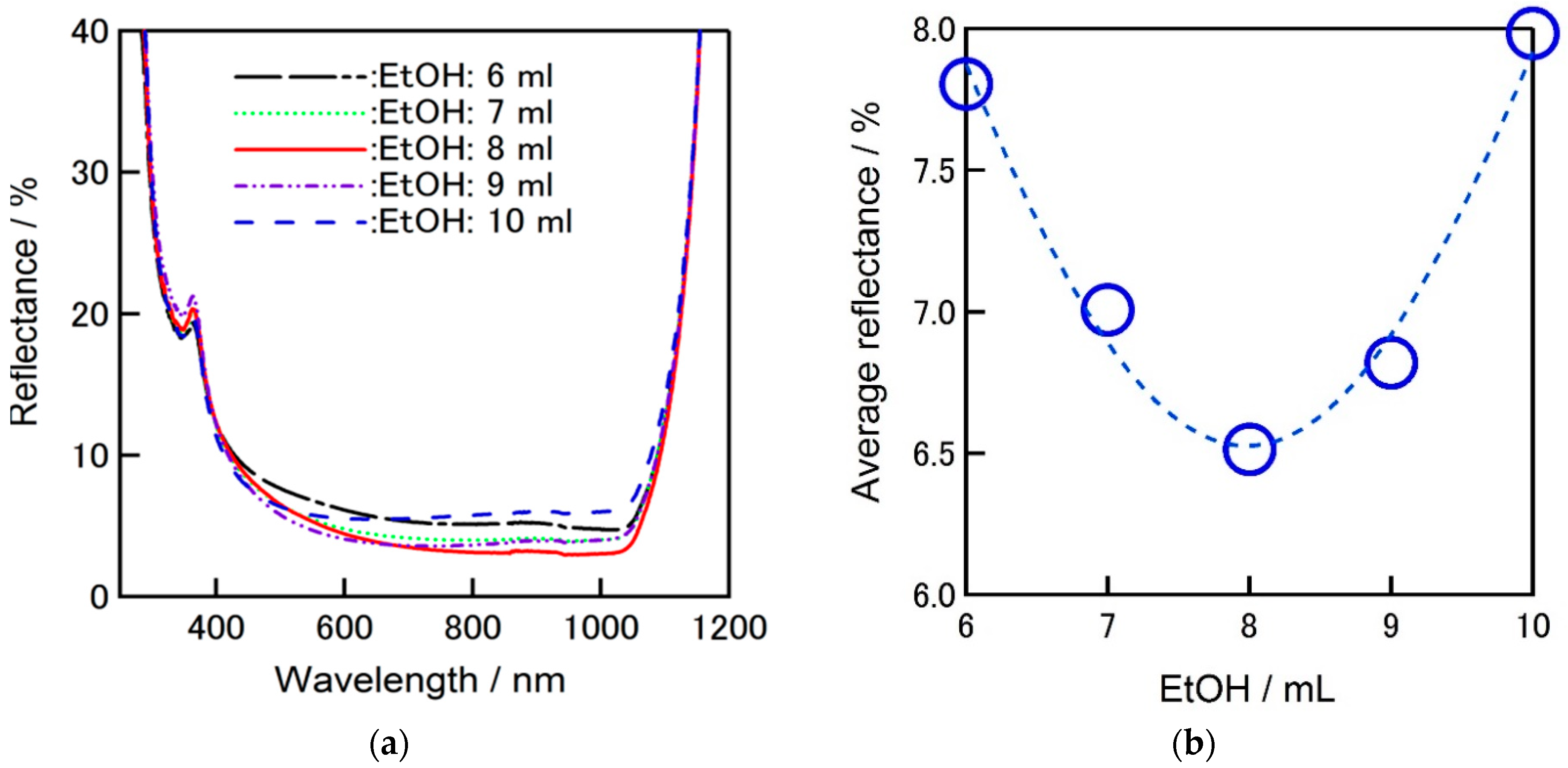
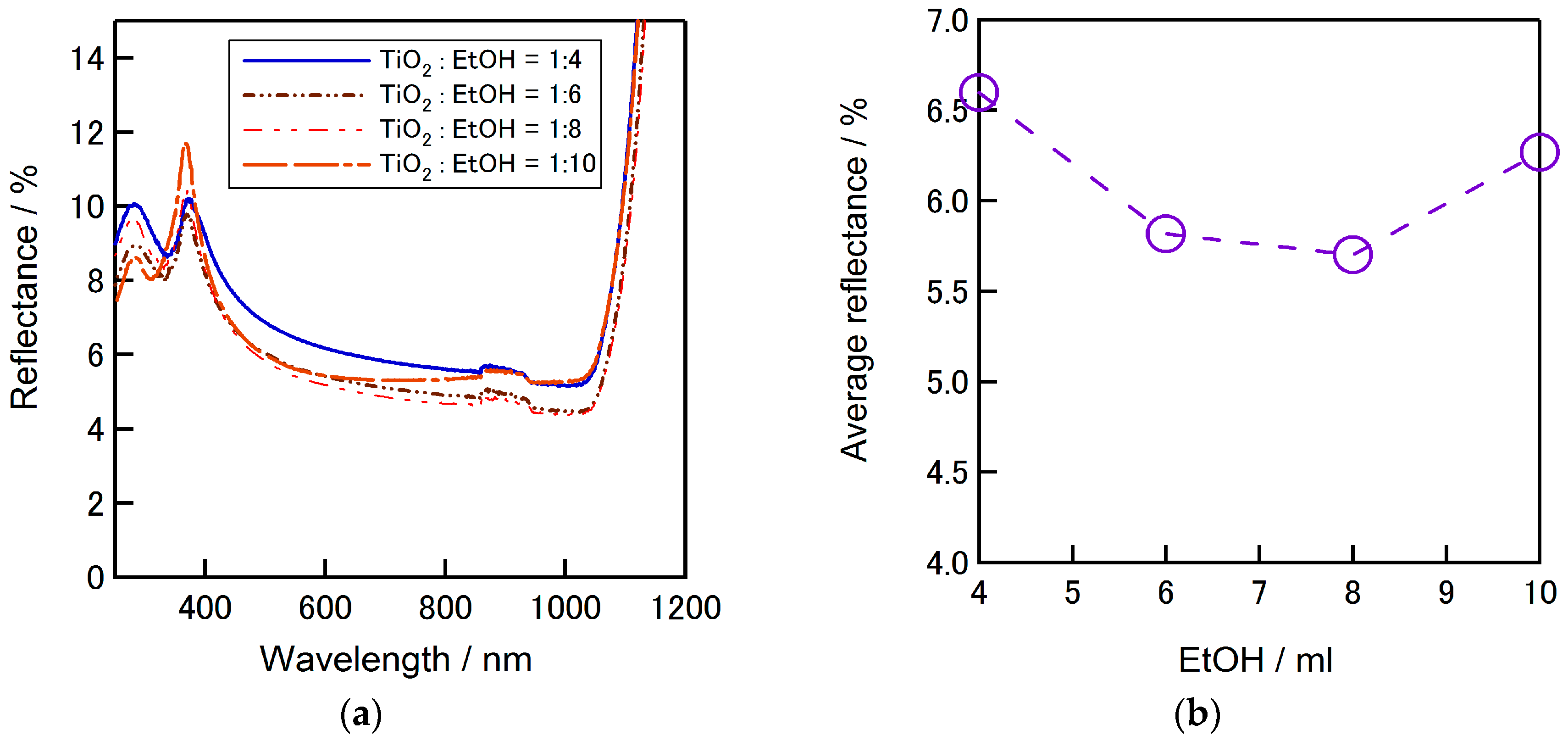
Figure 8a shows the comparison of the reflectivity of textured silicon wafers covered by ZrO
2-P composite film including different amount of ethanol in the solution. Average reflectance was decreased from 8% down to 6.5%, when 8 mL (91.4%vl) ethanol is used in total zirconium solution (0.5 mL zirconium solution (5.71%vl) + 0.25 mL ethyl cellulose (2.85%vl)).
Figure 8b clearly shows that there is a breaking point for the amount of ethanol used in zirconium solution to achieve better reflectance performance which is the main agent to adjust the viscosity.
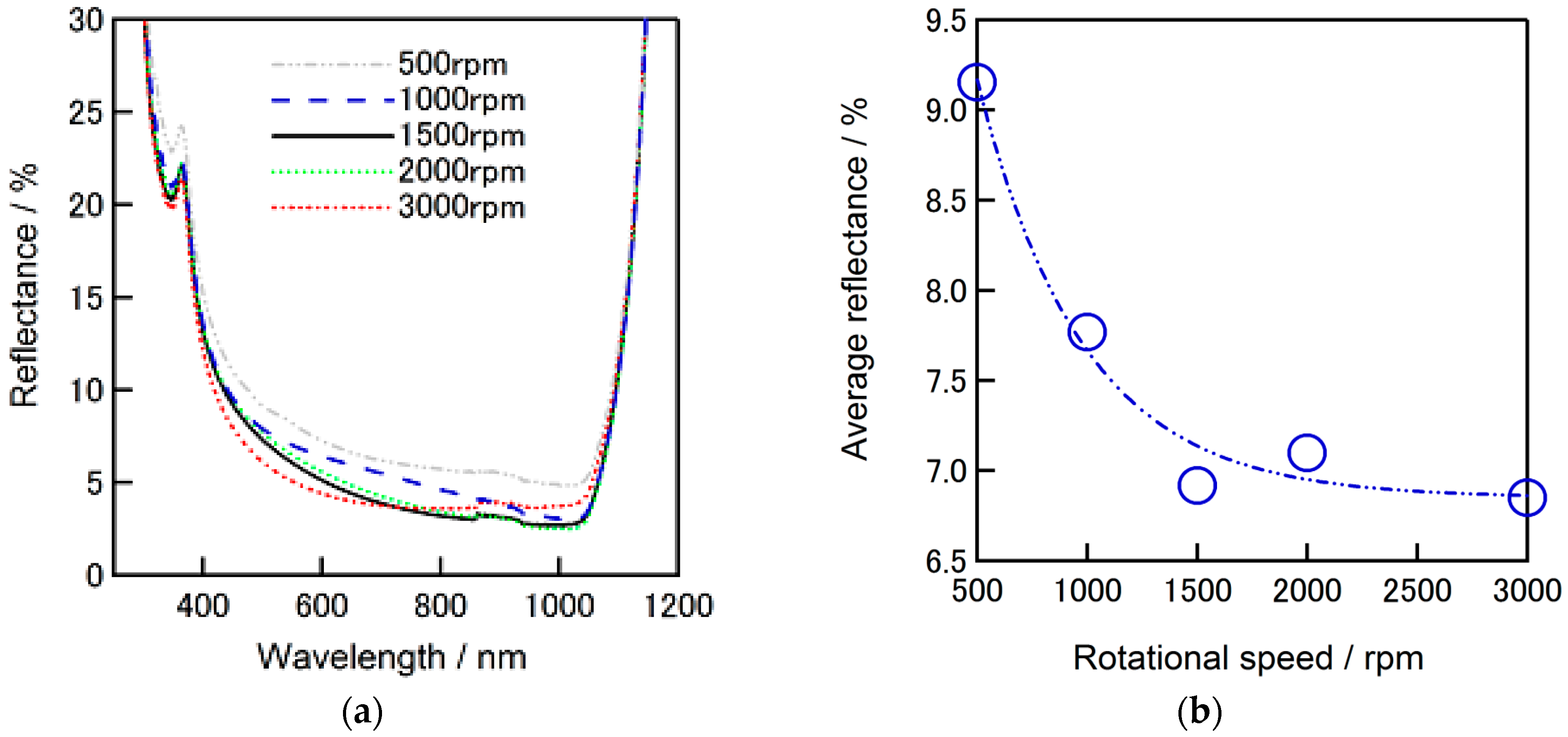
Reflectance dependence of ZrO
2-P composite film coated alkaline textured silicon substrates on the applied spin speed is given in
Figure 9a. Deposition was performed by spin-on coating with a spin-speed in a range of 500–3000 rpm. A gradual decrease of reflectance was observed with increase of spin speed and becomes relatively stable after 1500 rpm. Average reflectance of lower than 7% was confirmed when the spin speeds is 1500 rpm. The dependence of reflectance to the spin speed is given in
Figure 9b. These results further support the benefit of ZrO
2-P composite film on decreasing the reflectance when formed on a silicon substrate.
Evaluations of SD-TiO
2 solution were also carried out both on flat or textured silicon substrate. In 1 mL SD-TiO
2 solution, 0.1 mL of ethyl cellulose was added and the amount of ethanol was varied from 4 to 10 mL. Prepared solution was spun on flat silicon surface and annealed on a hot plate at 125 °C for 5 min.
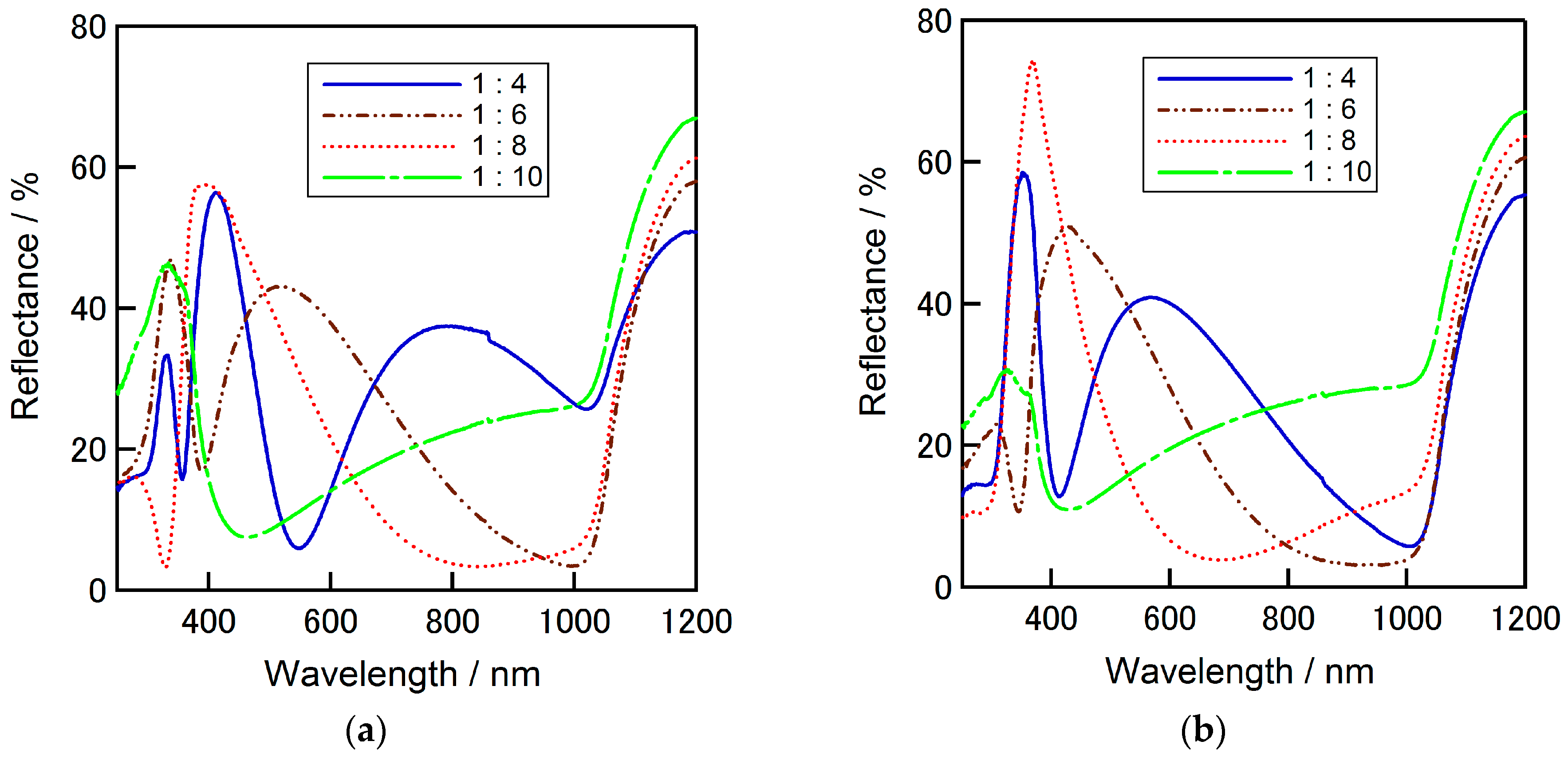
Figure 10 shows the reflectivity of flat silicon surface coated with TiO
2 solution with varied amount of ethanol in precursor, with spin speed of 5000 rpm or 8000 rpm. In
Table 1, the average reflectance of flat silicon surface coated with surface deactivated TiO
2-ethyl cellulose film is summarized for each amount of ethanol in the solution.
The lowest average reflectance was observed when the amount of ethanol is 8 mL, as of 19.92% and 20.04% for spin speed of 5000 rpm and 8000 rpm, respectively.
Figure 11a presents the reflectivity of textured silicon surface coated with SD-TiO
2-P film. The amount of ethanol was varied similarly from 4 to 10 mL. From the figure it can be confirmed that the coated film with the precursor include 8 mL of ethanol provides the lowest reflectance. The average reflectance tendency depends on the ethanol amount can be seen in
Figure 11b where the lowest average reflectance is around 5.6%.
3.2. Simulation and Formation of ZrO2-Polymer/Surface-Passivated TiO2-Polymer Composite Multilayer Film
After evaluating the ZrO
2-P and SD-TiO
2-P composite thin films separately, an <air/ZrO
2-polymer/surface-passivated TiO
2-polymer/Si> multilayer structure was also built considering that the reflectance can be reduced significantly with multilayer films [
20] where the layers should be deposited with gradual increase order of their refractive indexes, as n
air < n
ZrO2-polymer < n
TiO2-polymer < n
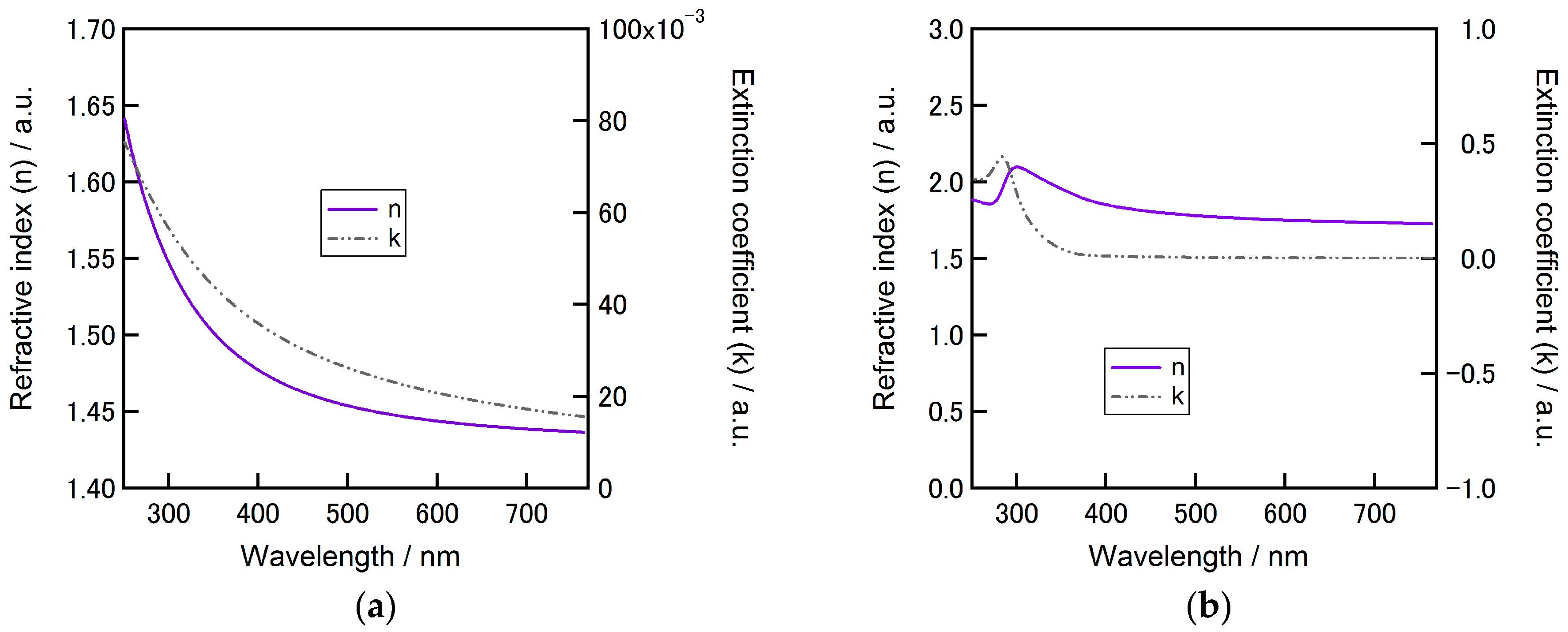
silicon, in this work. The refractive indexes and extinction coefficients of ZrO
2-P and SD-TiO
2-P composite layers achieved by fitting of the ellipsometry measurements are shown in
Figure 12a,b, respectively. As such, refractive indexes of air and silicon wafer are 1 and 4.3, respectively.
A simulation study was carried out for the <air/ZrO
2-polymer (ZrO
2-P)/surface-deactivated TiO
2-polymer (SD-TiO
2-P)/Si> structure in order to estimate the short circuit current density (
Jsc) density. Fresnel equations were followed by considering the measured refractive indexes of each layer in order to achieve an ideal reflectance of the total structure [
24]. Fresnel approach reduces multi number of layer structure to a single imaginary layer by taking account the refractive index and thickness of each layer in the multi structure and is based on the transmittance and the reflectance waves from the corresponding layers.
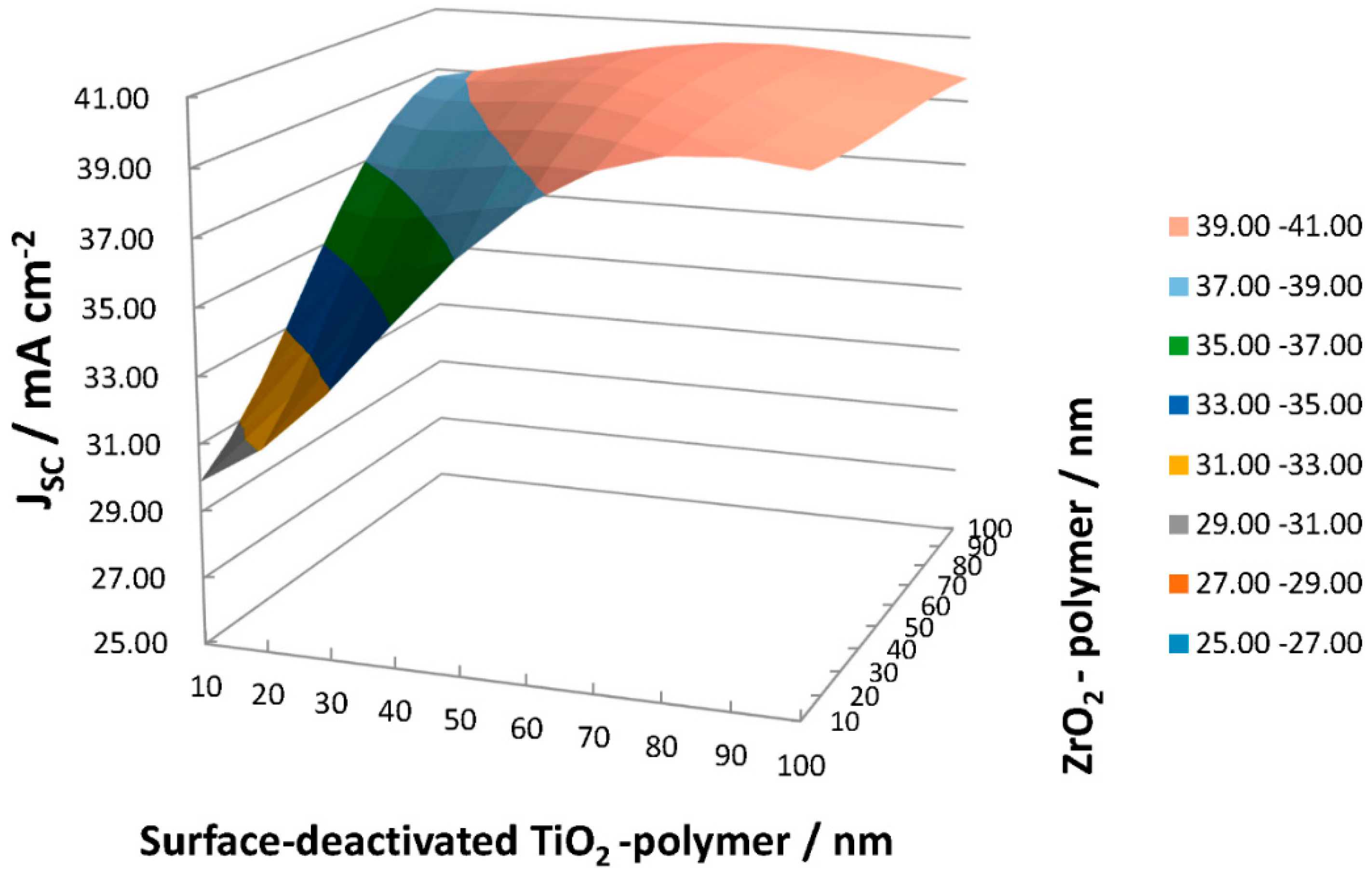
The thicknesses of the ZrO
2-P and SD-TiO
2-P composite layers were varied from 10 to 100 nm, and “Incident Photon to Current Conversion Efficiency (IPCE)” was assumed 100% for the calculation.
Jsc was calculated using the Equation (1) in order to observe the ideal ZrO
2-P and SD-TiO
2-P composite film thicknesses to obtain an efficient ZrO
2-P/SD-TiO
2-P composite multilayer ARC film:
where “
Jsc,max” is maximum short circuit current density in mA cm
−2, “e” is stands for charge of an electron (1.602 × 10
–19 C), “h” is Plank’s constant (6.626 × 10
–34 Js), “c” is speed of light (2.998 × 10⁸ m·s
−1), “Pin” is the incident power in W/m
2, and “λ” is the wavelength in nm.
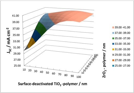
Figure 13 presents the estimated
Jsc with ZrO
2-P/SD-TiO
2-P composite ARC film on c-Si solar cells. A summary of the estimated values of
Jsc can be seen in
Table 2 for each thickness combination of the layers.
Maximum JSC of 40.83 mA cm−2 was achieved with <t = 60 nm ZrO2-P/t = 70 nm SD-TiO2-P> multilayer ARC film. It is notable that increased values of Jsc of ~40 mA cm-2 become achievable with the thickness of >50 nm of each layer.
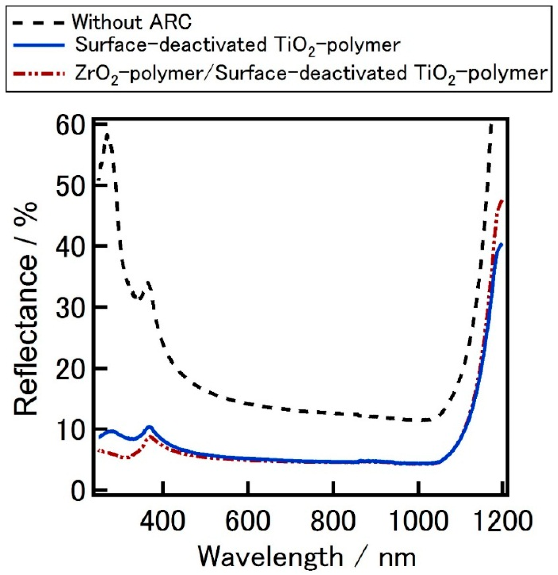
To form and characterize such a multilayer film experimentally, first SD-TiO
2-P film was spin coated on the textured silicon surface and annealed at 125 °C for 5 min, then the reflectance of the surface was measured. After the measurement ZrO
2-P film was spin coated on SD-TiO
2-P film and annealed similarly. The comparison of reflectance spectra of textured silicon surface coated with SD-TiO
2-P film or the ZrO
2-P/SD-TiO
2-P composite multilayer film is given in
Figure 14. Average reflectance of the silicon surface was improved due to the multilayer ARC where the average reflectance is around 5.5% for multilayer structure (average reflectance without ARC = 16.3%).
Additionally, lifetime analysis was carried out in order to estimate the passivation effect of purposed ARC films. Four sets of samples (three samples per set) were prepared for lifetime studies; TiO2-P (set 1), ZrO2-P (set 2), SP-TiO2-P (set 3), ZrO2-P/SP-TiO2-P (set 4). All samples went through an acidic etching of HF:HNO3 (1:5vl%) for 5 min and then received UV/O3 treatment for 15 min before the film deposition. ARC films were spin coated on both sides of the wafers at 5000 rpm for 25 s (acceleration time is 5 s) and were annealed at 125 °C for 5 min.
Lifetime measurements were carried out by microwave photoconductive decay (μ-PCD) technique. Bulk lifetime of a reference sample was measured using chemical passivation (ethanol:iodine, 0.025 M) and measured as 527 μs. Samples of each set (neighbor samples cut from the same large area CZ p-type silicon wafer) were measured before (without ARC) and after forming the ARC film. Measured lifetimes are shown in
Table 3. Although a slight increase of lifetimes was observed stable for those of the wafers coated with TiO
2-P or ZrO
2-P/SP-TiO
2-P multilayer ARC, however the increase was negligibly small. The maximum lifetime increases of around 0.9 μs were observed on ZrO
2-P/SP-TiO
2-P multilayer ARC coated wafers. These results show that there is no significant passivation effect of our ARC films.
3.3. Evaluation of the Fabricated p-type Crystalline Silicon Solar Cells
After the evaluation of the ARC films, CZ-Si p-type solar cells were fabricated by applying ZrO
2-P, SD-TiO
2-P composite films and ZrO
2-P/SD-TiO
2-P composite multilayer structure films as ARC layer and compared with those of the cells fabricated without any ARC film. The electrical characteristics of the fabricated solar cells with (w/) or without (w/o) ZrO
2-P composite ARC are summarized in
Table 4.
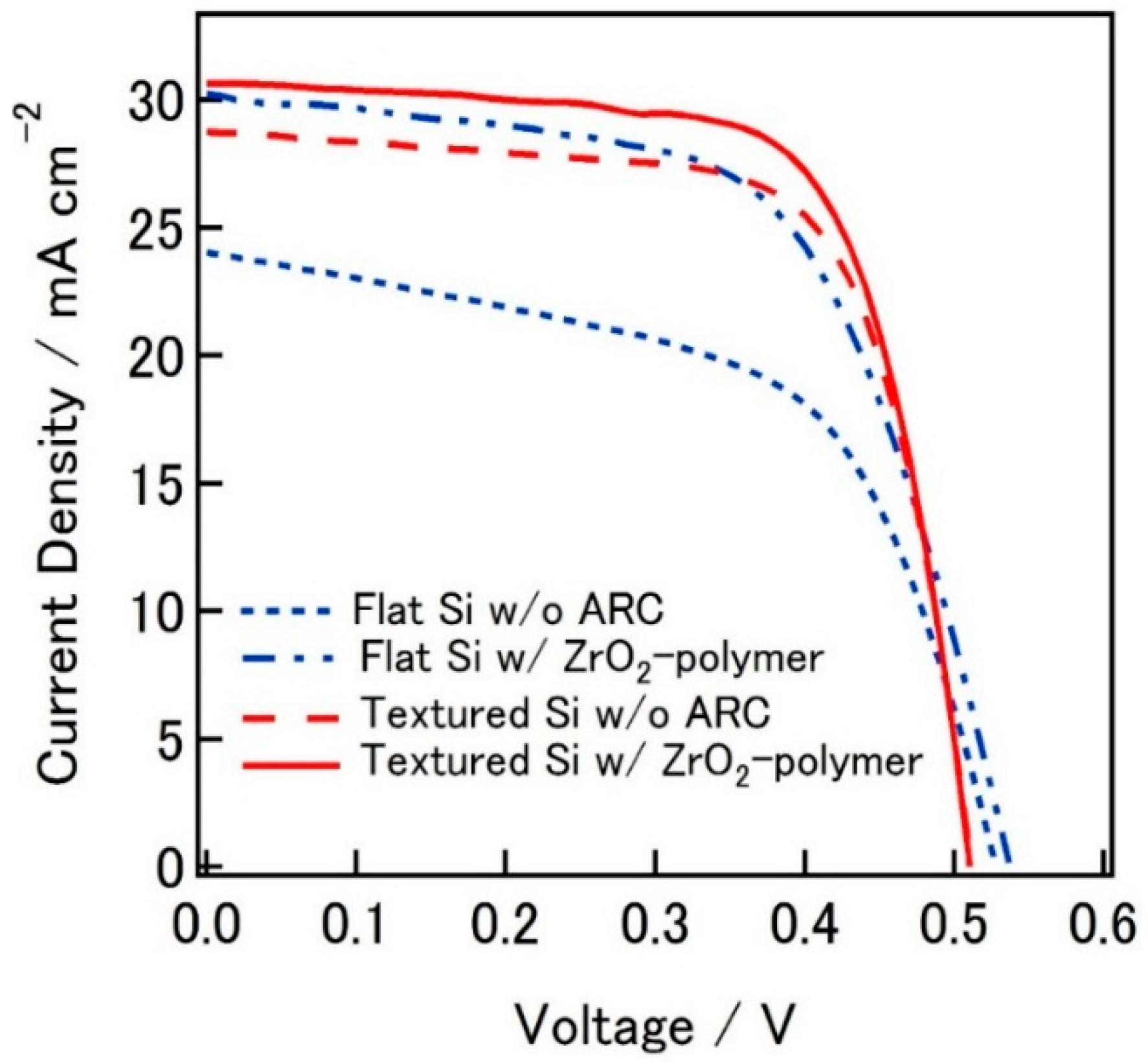
Conversion efficiency of the best cell fabricated on flat silicon substrate w/o ZrO
2-P composite ARC on the surface was 7.25% with
Jsc and open circuit voltage (
Voc) of 24.03 mA cm
−2, 527 mV, respectively. Conversion efficiency of the cell w/ ZrO
2-P composite ARC, reaches 9.78% with
Jsc of 30.22 mA cm
−2, owing to the light trapping by ZrO
2-P composite ARC film.
Jsc of the solar cells fabricated on textured silicon substrates increase up to 29.74 mA cm
−2 (w/o ZrO
2-P ARC) and 30.62 mA cm
−2 (w/ ZrO
2-P ARC) due to reduced reflection by textured surface and ZrO
2-P composite ARC film. Conversion efficiencies of the solar cells with textured surface were 10.2% and 10.9 for those cells w/ and w/o ZrO
2-P ARC, respectively.
Figure 15 presents the
J-V curve comparison of the best cells for each set.
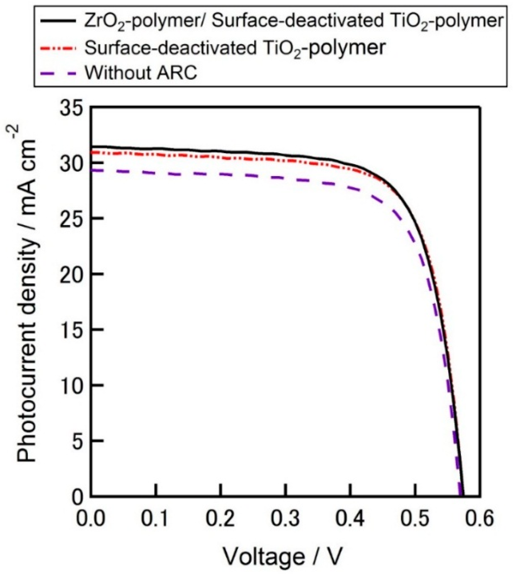
On the other hand, solar cells with SD-TiO
2-P ARC and ZrO
2-P/SD-TiO
2-P composite multilayer ARC were also fabricated.
Jsc of 30.93 mA cm
−2 and
Voc of 569 mV were achieved when solar cells fabricated w/o any ARC (average of three samples). Average
Jsc of the solar cell with SD-TiO
2-P composite film and ZrO
2-P/SD-TiO
2-P composite multilayer film as ARC increased up to 32.44 and 33.00 mA cm
−2, respectively. These increases of
Jsc are attributed to the decrease of the reflectance with ARCs which increases the optical performance of the solar cells. Average efficiencies of the three fabricated cells for each set, w/o ARC, w/ SD-TiO
2-P film and w/ ZrO
2-P/SD-TiO
2-P composite multilayer structure film were 11.99%, 12.84%, and 12.85%, respectively.
Table 5 summarizes the electrical characteristics of the fabricated solar cells. Efficiency of the solar cells improved by a factor of 0.86% with an increase of
Jsc (2.07 mA cm
−2) by the contribution of ZrO
2-P/SD-TiO
2-P ARC composite multilayer compared to those of fabricated without the ARC. The best efficiency of 12.91% for the cells with ZrO
2-P/SD-TiO
2-P composite multilayer structure ARC film was achieved with
Jsc of 31.42 mA cm
−2,
Voc of 575 mV, and fill factor (
FF) of 71.5%. The
J-V curve comparison of the best cells for each set is given in
Figure 16. The higher average
Jsc of the cells than that of the best cells in spite of lower
FF may draw the attention which can be attributed to the ARC effect. Because the lower series resistances of the best cells might be due to the lower contact resistance owing to the better contact formation between the metal contacts and silicon during the firing steps which lead higher
FF.
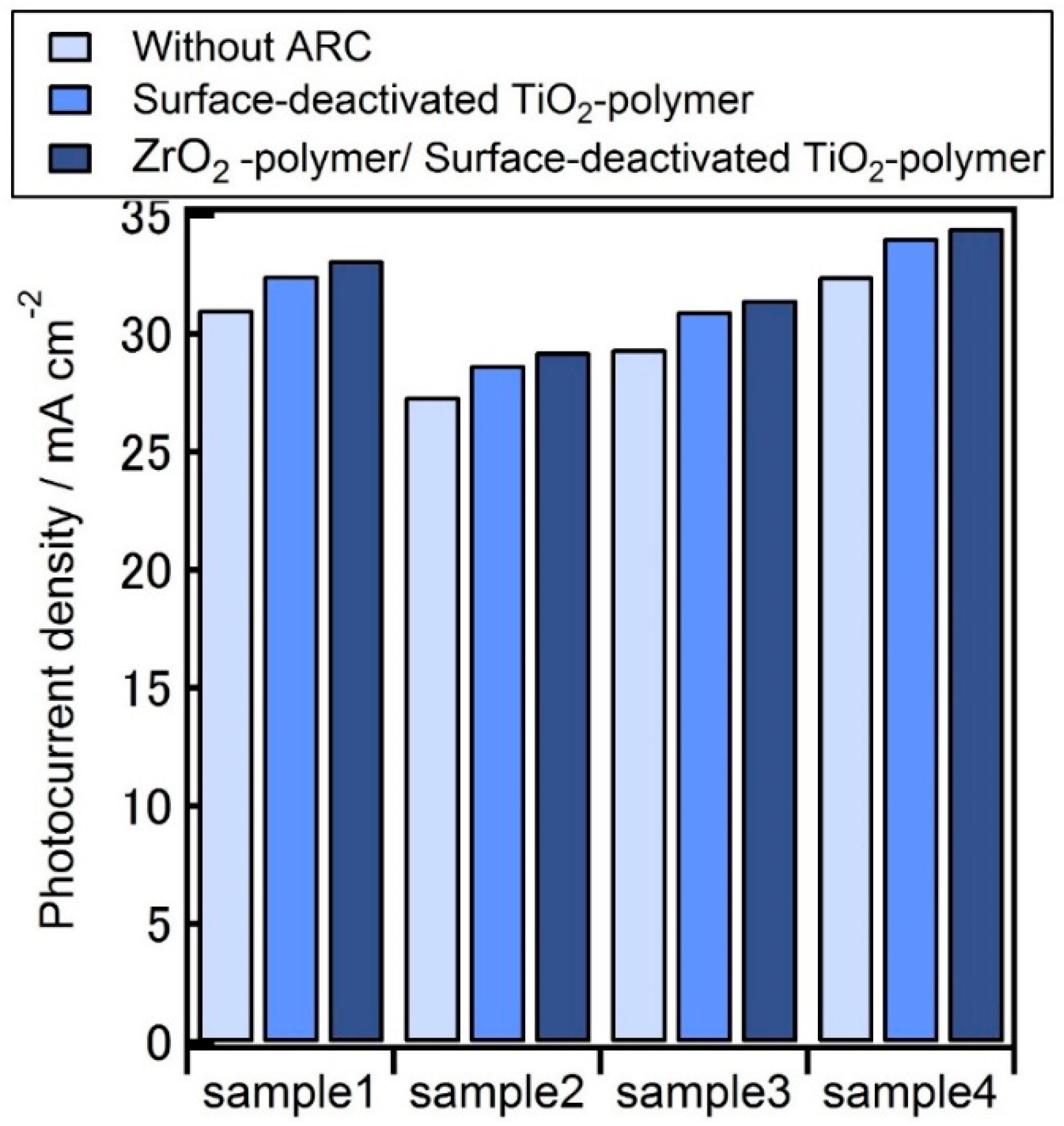
The improvement of
Jsc by SD-TiO
2-P or ZrO
2-P/SD-TiO
2-P multilayer ARC composite can be clearly seen in
Figure 17, where the
Jsc increases gradually for all samples by SD-TiO
2-P single layer ARC and ZrO
2-P/SD-TiO
2-P multilayer ARC composite.
Jsc increases (average of four samples) from 30.04 to up to 32.07 mA cm
−2. In order to discuss the statistical errors about the resulting silicon solar cells, the number of samples was not enough because just four cells have been fabricated for
Figure 17. However, every cell improved the
Jsc with sequential addition of the TiO
2-P and ZrO
2-P composite coating on the silicon surface. Hence, it was enough to understand the merit for the polymer composite layers to be the antireflection coatings.
It should be noted that the limited overall cell performance in this work, compared to commercially available, fully state-of-art solar cells can be mainly attributed to the low lifetime of silicon substrates and inadequate bulk passivation which can cause poor Voc and to the low FF s which can be due to the lack of proper edge isolation of the finished cells. These results suggest that ZrO2-P/SD-TiO2-P composite multilayer structure ARC film formed by spin coating deposition technique could be beneficial and promising alternative as a low-cost, simple and vacuum-less process for ARC for silicon solar cells. Further investigations are on progress to achieve better performances on ARC utilizing polymer based ZrO2 composite layers and its multilayer structures.


