
Unshrouded Plate Fin Heat Sinks for Electronics Cooling: Validation of a Comprehensive Thermal Model and Cost Optimization in Semi-Active Configuration

 , and
, and
Abstract
:
1. Introduction
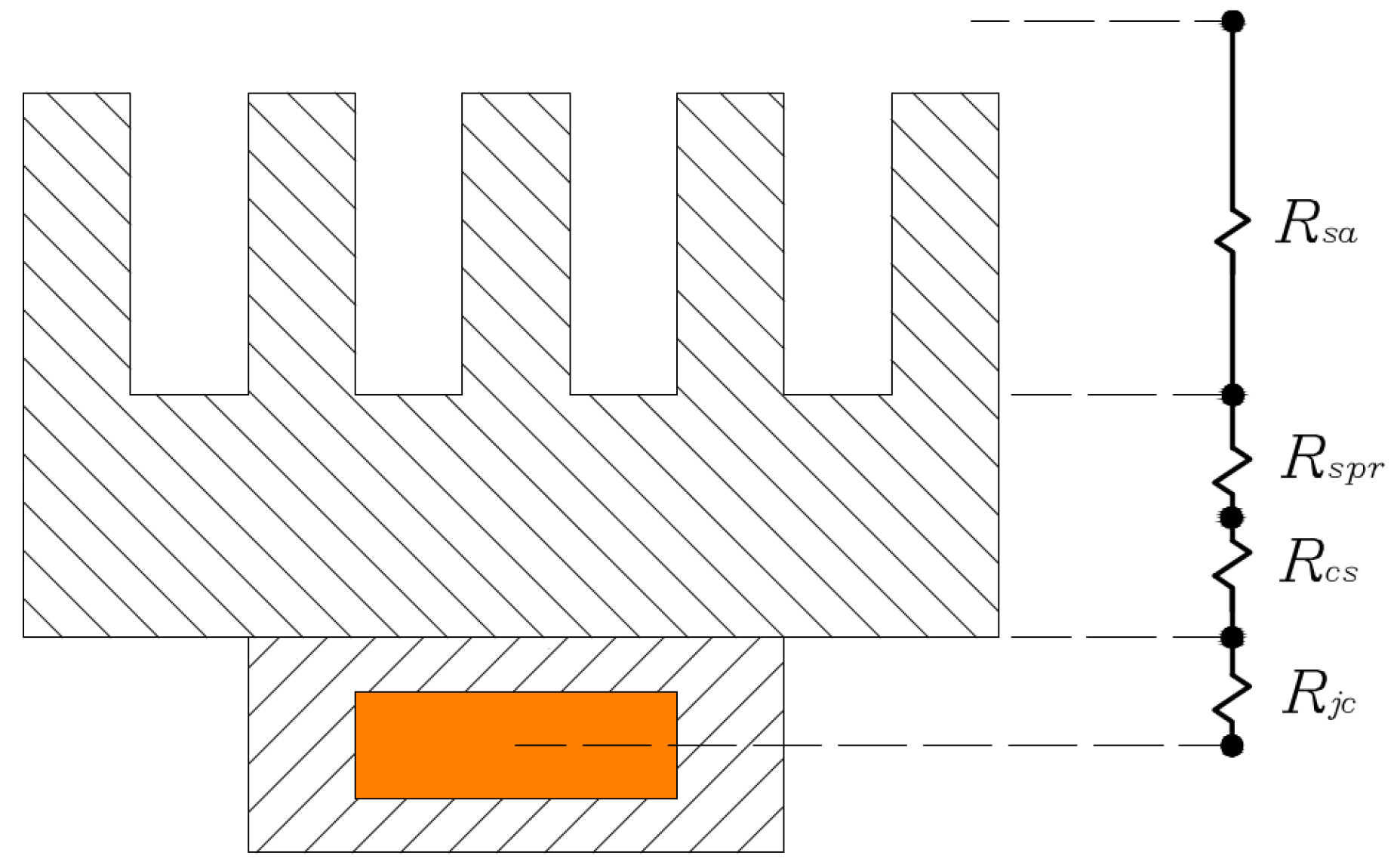
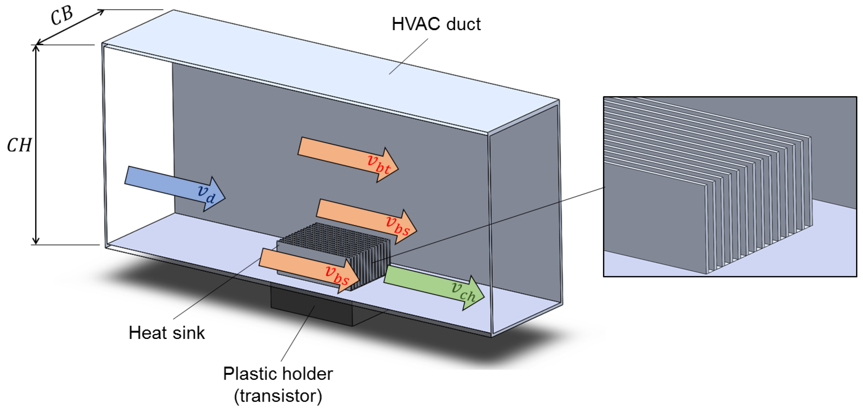
2. Theoretical Analysis
3. Results and Discussion
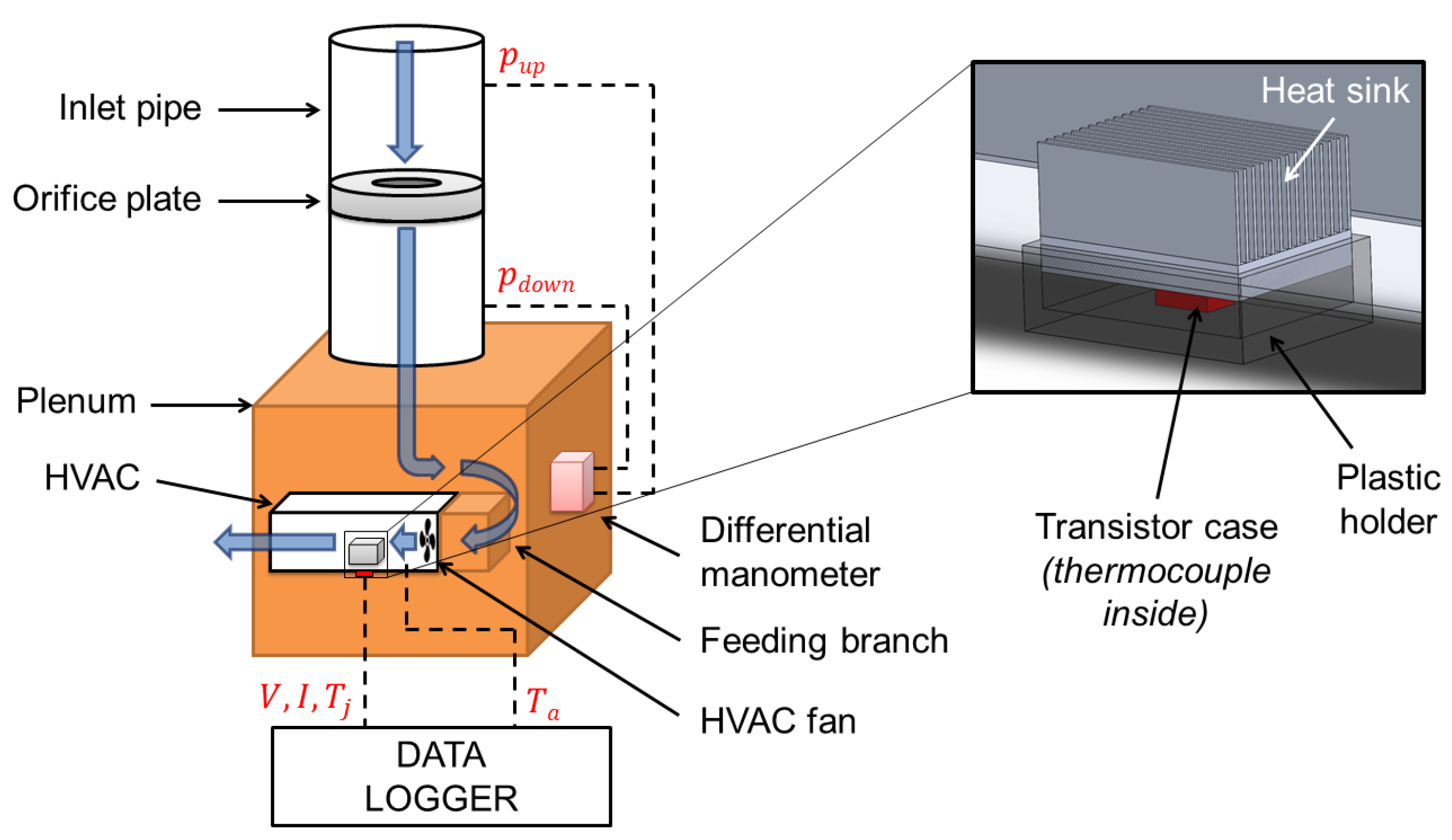
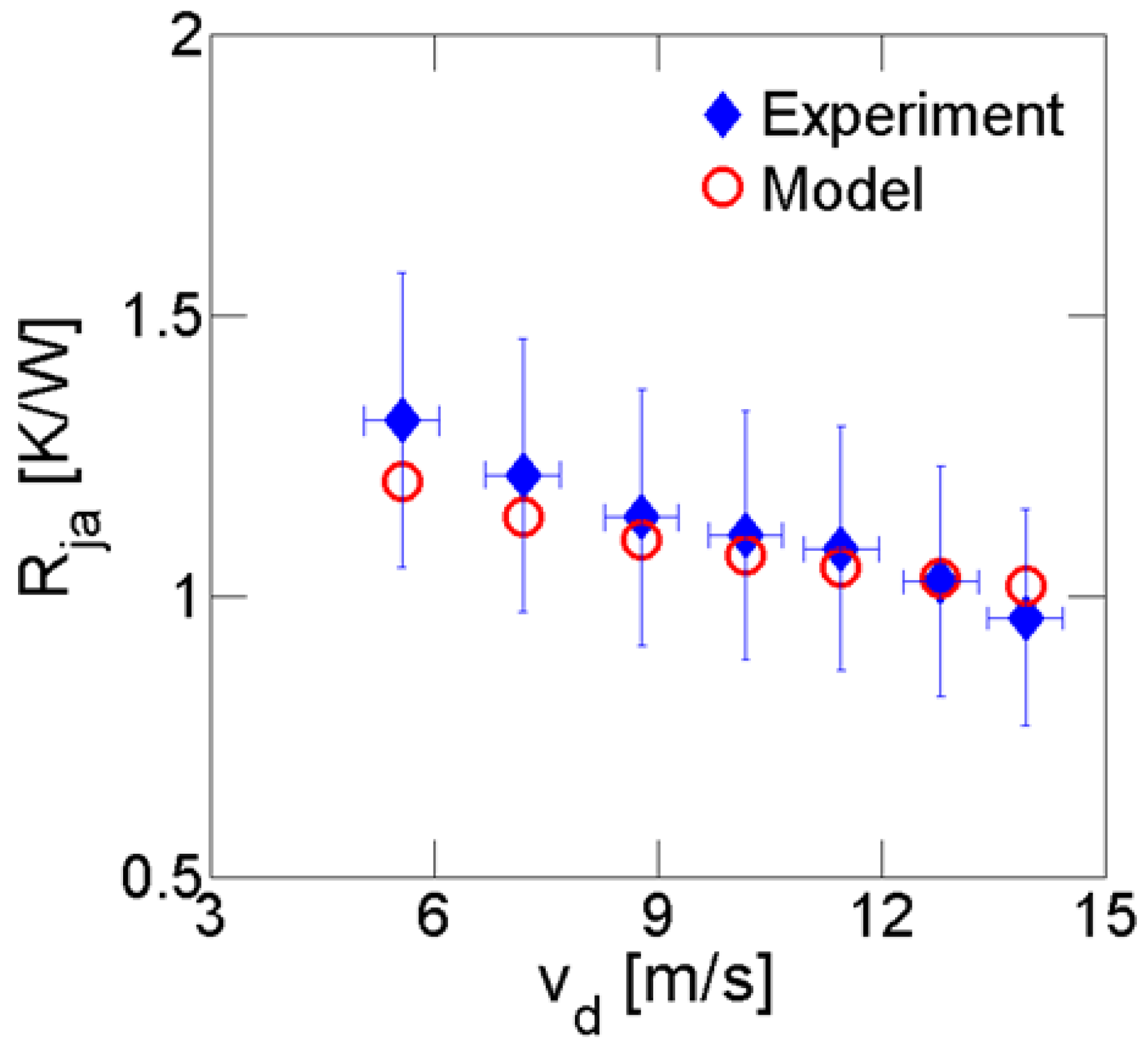
3.1. Experimental Validation
3.2. Optimization Procedure and Results
4. Conclusions
Acknowledgments
Author Contributions
Conflicts of Interest
Abbreviations
| a | air |
| app | apparent |
| b | baseplate |
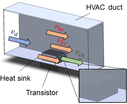
| bs | side bypass |
| bt | top bypass |
| ch | channel |
| d | approach |
| e | experimental |
| f | fins |
| hs | heat sink |
| j | junction |
| m | model |
| p | spacing |
| ref | reference |
| s | heat source |
| W | working |
Appendix A: Detailed Model for Pressure Drops
Appendix B: Genetic Algorithm Settings and Performances
References
- Gillot, C.; Bricard, A.; Schaeffer, C. Single- and two-phase heat exchangers for power electronic components. Int. J. Therm. Sci. 2000, 39, 826–832. [Google Scholar] [CrossRef]
- Garimella, S.V.; Fleischer, A.; Murthy, J.Y.; Keshavarzi, A.; Prasher, R.; Patel, C.; Bhavnani, S.; Venkatasubramanian, R.; Mahajan, R.; Joshi, Y.; et al. Thermal Challenges in Next-Generation Electronic Systems. IEEE Trans. Compon. Packag. Technol. 2008, 31, 801–815. [Google Scholar] [CrossRef]
- Remsburg, R. Advanced Thermal Design of Electronic Equipment; Chapman & Hall: New York, NY, USA, 1998. [Google Scholar]
- Khan, W.A.; Culham, J.; Yovanovich, M. The Role of Fin Geometry in Heat Sink Performance. ASME J. Electron. Packag. 2006, 128, 324–330. [Google Scholar] [CrossRef]
- Yeh, H.M.; Ho, C.D. Collector Efficiency in Downward-Type Internal-Recycle Solar Air Heaters with Attached Fins. Energies 2013, 6, 5130–5144. [Google Scholar] [CrossRef]
- Wang, G.L.; Yang, D.W.; Wang, Y.; Niu, D.; Zhao, X.L.; Ding, G.F. Heat Transfer and Friction Characteristics of the Microfluidic Heat Sink with Variously-Shaped Ribs for Chip Cooling. Sensors 2015, 15, 9547–9562. [Google Scholar] [CrossRef] [PubMed]
- Ahn, B.L.; Park, J.W.; Yoo, S.; Kim, J.; Leigh, S.B.; Jang, C.Y. Savings in Cooling Energy with a Thermal Management System for LED Lighting in Office Buildings. Energies 2015, 8, 6658–6671. [Google Scholar] [CrossRef]
- Jeong, M.W.; Jeon, S.W.; Kim, Y. Optimal thermal design of a horizontal fin heat sink with a modified-opening model mounted on an LED module. Appl. Therm. Eng. 2015, 91, 105–115. [Google Scholar] [CrossRef]
- Jeng, T.M.; Tzeng, S.C.; Yang, B.J.; Li, Y.C. Design, Manufacture and Performance Test of the Thermoelectric Generator System for Waste Heat Recovery of Engine Exhaust. Inventions 2016, 1, 2. [Google Scholar] [CrossRef]
- Yang, Y.T.; Tang, H.W.; Ding, W.P. Optimization design of micro-channel heat sink using nanofluid by numerical simulation coupled with genetic algorithm. Int. Commun. Heat Mass Transf. 2016, 72, 29–38. [Google Scholar] [CrossRef]
- Diani, A.; Mancin, S.; Zilio, C.; Rossetto, L. An assessment on air forced convection on extended surfaces: Experimental results and numerical modeling. Int. J. Therm. Sci. 2013, 67, 120–134. [Google Scholar] [CrossRef]
- Shaalan, R.; Saleh, A.; Mesalhy, O.; Elsayed, L. Thermo/fluid performance of a shielded heat sink. Int. J. Therm. Sci. 2012, 60, 171–181. [Google Scholar] [CrossRef]
- Lee, S. Optimum Design and Selection of Heat Sinks. IEEE Trans. Compon. Packag. Manuf. Technol. 1995, 18, 812–817. [Google Scholar] [CrossRef]
- Chen, A. Aluminum Extrusion Design and the Role it Plays in High Performance Cooling Solutions for Power Electronics. Available online: http://www.apec-conf.org/wp-content/uploads/IS3-3-1.pdf (accessed on 28 July 2016).
- Sparrow, E.; Baliga, B.; Patankar, S. Forced convection heat transfer from a shrouded fin array with and without tip clearance. J. Heat Transf. 1978, 100, 572–579. [Google Scholar] [CrossRef]
- Lau, K.; Mahajan, R. Effects of Tip Clearance and Fin Density on the Performance of Heat Sinks for VLSI Packages. IEEE Trans. Compon. Hybrids Manuf. Technol. 1989, 12, 757–765. [Google Scholar] [CrossRef]
- Lee, R.; Huang, H.; Chen, W. A thermal characteristic study of extruded-type heat sinks in considering air flow bypass phenomenon. In Proeedings of the Sixth Annual IEEE Semiconductor Thermal and Temperature Measurement Symposium, Phoenix, AZ, USA, 6–8 February 1990; pp. 95–102.
- Iwasaki, H.; Sasaki, T.; Ishizuka, M. Cooling performance of plate fins for multichip modules. In Proceedings of the InterSociety Conference on Thermal Phenomena in Electronic Systems, Concurrent Engineering and Thermal Phenomena, Washington, DC, USA, 4–7 May 1994; pp. 144–147.
- Wirtz, R.A.; Chen, W.; Zhou, R. Effect of flow bypass on the performance of longitudinal fin heat sinks. J. Electron. Packag. 1994, 116, 206–211. [Google Scholar] [CrossRef]
- Jousson, H.; Palm, B. Thermal and hydraulic behavior of plate fin and strip fin heat sinks under varying bypass conditions. IEEE Trans. Compon. Packag. Technol. 2000, 23, 47–54. [Google Scholar] [CrossRef]
- Ishizuka, M.; Yokono, Y.; Biswas, D. Experimental study on the performance of a compact heat sink for LSI packages. Proc. Inst. Mech. Eng. Part A: J. Power Energy 2000, 214, 523–530. [Google Scholar] [CrossRef]
- Chen, H.T.; Lai, S.T.; Haung, L.Y. Investigation of heat transfer characteristics in plate-fin heat sink. Appl. Therm. Eng. 2013, 50, 352–360. [Google Scholar] [CrossRef]
- Wu, H.H.; Hsiao, Y.Y.; Huang, H.S.; Tang, P.H.; Chen, S.L. A practical plate-fin heat sink model. Appl. Therm. Eng. 2011, 31, 984–992. [Google Scholar] [CrossRef]
- Saini, M.; Webb, R.L. Heat rejection limits of air cooled plane fin heat sinks for computer cooling. IEEE Trans. Compon. Packag. Technol. 2003, 26, 71–79. [Google Scholar] [CrossRef]
- Bejan, A. Entropy Generation Minimization: The Method of Thermodynamic Optimization of Finite-Size Systems and Finite-Time Processes; CRC Press: Boca Raton, FL, USA, 1995. [Google Scholar]
- Culham, J.; Muzychka, Y. Optimization of plate fin heat sinks using entropy generation minimization. IEEE Trans. Compon. Packag. Technol. 2001, 24, 159–165. [Google Scholar] [CrossRef]
- Shih, C.; Liu, G. Optimal design methodology of plate-fin heat sinks for electronic cooling using entropy generation strategy. IEEE Trans. Compon. Packag. Technol. 2004, 27, 551–559. [Google Scholar] [CrossRef]
- Betchen, L.J.; Straatman, A.G. A computational method for geometric optimization of enhanced heat transfer devices based upon entropy generation minimization. Int. J. Numer. Methods Fluids 2013, 71, 370–402. [Google Scholar] [CrossRef]
- Bar-Cohen, A.; Iyengar, M. Design and optimization of air-cooled heat sinks for sustainable development. IEEE Trans. Compon. Packag. Technol. 2002, 25, 584–591. [Google Scholar] [CrossRef]
- Iyengar, M.; Bar-Cohen, A. Least-energy optimization of forced convection plate-fin heat sinks. IEEE Trans. Compon. Packag. Technol. 2003, 26, 62–70. [Google Scholar] [CrossRef]
- Bar-Cohen, A.; Iyengar, M. Least-energy optimization of air-cooled heat sinks for sustainable development. IEEE Trans. Compon. Packag. Technol. 2003, 26, 16–25. [Google Scholar] [CrossRef]
- Bar-Cohen, A.; Bahadur, R.; Iyengar, M. Least-energy optimization of air-cooled heat sinks for sustainability-theory, geometry and material selection. Energy 2006, 31, 579–619. [Google Scholar] [CrossRef]
- Ahmadi, P.; Hajabdollahi, H.; Dincer, I. Cost and entropy generation minimization of a cross-flow plate fin heat exchanger using multi-objective genetic algorithm. J. Heat Transf. 2011, 133, 021801. [Google Scholar] [CrossRef]
- Chen, C.; Chen, H. Multi-objective optimization design of plate-fin heat sinks using a direction-based genetic algorithm. J. Taiwan Inst. Chem. Eng. 2013, 44, 257–265. [Google Scholar] [CrossRef]
- Horng, J.T.; Chang, S.F.; Wu, T.Y.; Chen, P.L.; Hung, Y.H. Thermal optimal design for plain plate-fin heat sinks by using neuro-genetic method. IEEE Trans. Compon. Packag. Technol. 2008, 31, 449–460. [Google Scholar] [CrossRef]
- Park, K.; Oh, P.K.; Lim, H.J. The application of the CFD and Kriging method to an optimization of heat sink. Int. J. Heat Mass Transf. 2006, 49, 3439–3447. [Google Scholar] [CrossRef]
- Zhou, J.; Yang, C.; Zhang, L. Minimizing the entropy generation rate of the plate-finned heat sinks using computational fluid dynamics and combined optimization. Appl. Therm. Eng. 2009, 29, 1872–1879. [Google Scholar]
- Culham, J.; Khan, W.A.; Yovanovich, M.; Muzychka, Y. The Influence of Material Properties and Spreading Resistance in the Thermal Design of Plate Fin Heat Sinks. J. Electron. Packag. 2007, 129, 76–81. [Google Scholar] [CrossRef]
- Hossain, R.; Culham, J.; Yovanovich, M. Influence of Bypass on Flow Through Plate Fin Heat Sinks. In Proceedings of the 23rd IEEE Semiconductor Thermal Measurement and Management Symposium, San Jose, CA, USA, 18–22 March 2007; pp. 220–227.
- Teertstra, P.; Yovanovich, M.; Culham, J.; Lemczyk, T. Analytical forced convection modeling of plate fin heat sinks. In Proceedings of the 15th IEEE Semiconductor Thermal Measurement and Management Symposium, San Diego, CA, USA, 9–11 March 1999; pp. 34–41.
- Chiavazzo, E.; Asinari, P. Reconstruction and modeling of 3D percolation networks of carbon fillers in a polymer matrix. Int. J. Therm. Sci. 2010, 49, 2272–2281. [Google Scholar] [CrossRef]
- Lee, S.; Song, S.; Au, V.; Moran, K. Constriction-spreading resistance model for electronic packaging. ASME/JSME Therm. Eng. Conf. 1995, 4, 199–206. [Google Scholar]
- Baker, R. Flow Measurement Handbook: Industrial Designs, Operating Principles, Performance, and Applications; Cambridge University Press: Cambridge, UK, 2005. [Google Scholar]
- Shahzad, M.I.; Giorcelli, M.; Ventola, L.; Perrone, D.; Shahzad, N.; Chiavazzo, E.; Asinari, P.; Cocuzza, M.; Tagliaferro, A. Convective Heat Transfer Enhancement for Electronic Device Applications Using Patterned MWCNTs Structures. Heat Transf. Eng. 2016, 37, 783–790. [Google Scholar] [CrossRef]
- Ventola, L.; Robotti, F.; Dialameh, M.; Calignano, F.; Manfredi, D.; Chiavazzo, E.; Asinari, P. Rough surfaces with enhanced heat transfer for electronics cooling by direct metal laser sintering. Int. J. Heat Mass Transf. 2014, 75, 58–74. [Google Scholar] [CrossRef]
- Chiavazzo, E.; Ventola, L.; Calignano, F.; Manfredi, D.; Asinari, P. A sensor for direct measurement of small convective heat fluxes: Validation and application to micro-structured surfaces. Exp. Therm. Fluid Sci. 2014, 55, 42–53. [Google Scholar] [CrossRef]
- Ventola, L.; Scaltrito, L.; Ferrero, S.; Maccioni, G.; Chiavazzo, E.; Asinari, P. Micro-structured rough surfaces by laser etching for heat transfer enhancement on flush mounted heat sinks. J. Phys. Conf. Ser. 2014, 525, 012017. [Google Scholar] [CrossRef]
- Ventola, L.; Chiavazzo, E.; Calignano, F.; Manfredi, D.; Asinari, P. Heat transfer enhancement by finned heat sinks with micro-structured roughness. J. Phys. Conf. Ser. 2014, 494, 012009. [Google Scholar] [CrossRef]
- Ventola, L.; Dialameh, M.; Fasano, M.; Chiavazzo, E.; Asinari, P. Convective heat transfer enhancement by diamond shaped micro-protruded patterns for heat sinks: Thermal fluid dynamic investigation and novel optimization methodology. Appl. Therm. Eng. 2016, 93, 1254–1263. [Google Scholar] [CrossRef]
- Fang, G.; Zhou, J.; Duszczyk, J. Extrusion of 7075 aluminium alloy through double-pocket dies to manufacture a complex profile. J. Mater. Process. Technol. 2009, 209, 3050–3059. [Google Scholar] [CrossRef]
- DENSO Thermal Systems; Poirino (TO), Italy. Private Communication, 15 July 2015.
- Kays, W.M.; London, A.L. Compact Heat Exchangers; McGraw-Hill: New York, NY, USA, 1984. [Google Scholar]
- Churchill, S.; Usagi, R. A general expression for the correlation of rates of transfer and other phenomena. AIChE J. 1972, 18, 1121–1128. [Google Scholar] [CrossRef]
- Yuan, B.; Gallagher, M. A hybrid approach to parameter tuning in genetic algorithms. IEEE Congr. Evol. Comput. 2005, 2, 1096–1103. [Google Scholar]
- Chiavazzo, E.; Fasano, M.; Asinari, P. Inference of analytical thermodynamic models for biological networks. Phys. A Stat. Mech. Appl. 2013, 392, 1122–1132. [Google Scholar] [CrossRef]


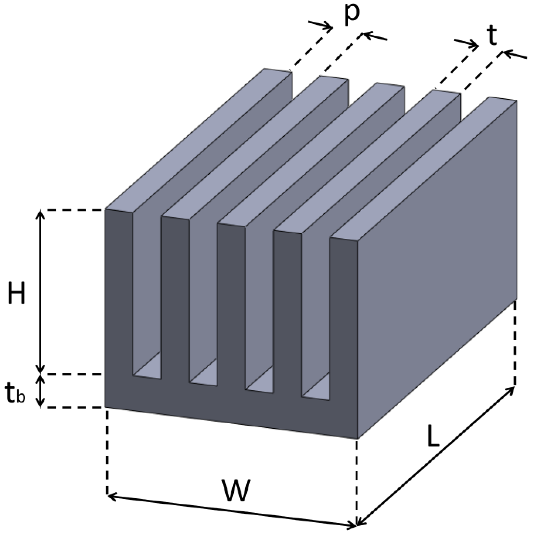
| L [mm] | W [mm] | [mm] | N [mm] | H [mm] | t [mm] | p [mm] |
|---|---|---|---|---|---|---|
| 57.2 | 41.4 | 8.4 | 14 | 21.8 | 1 | 2.1 |
| [m3/s] | P [W] | [°C] | [°C] | [m/s] | [K/W] |
|---|---|---|---|---|---|
| 0.136 | 60.24 | 84.4 | 26.5 | 13.9 | 0.96 |
| 0.125 | 76.3 | 104.3 | 26.1 | 12.8 | 1.02 |
| 0.112 | 85.07 | 118 | 25.8 | 11.5 | 1.08 |
| 0.099 | 87.32 | 121.9 | 25.1 | 10.2 | 1.11 |
| 0.086 | 82.36 | 118.7 | 24.8 | 8.8 | 1.14 |
| 0.070 | 71.4 | 111 | 24.2 | 7.2 | 1.22 |
| 0.054 | 56.64 | 98.1 | 23.8 | 5.6 | 1.31 |
| Deviation | |||||||
|---|---|---|---|---|---|---|---|
| [m/s] | [K/W] | [K/W] | [K/W] | [K/W] | [K/W] | [K/W] | [%] |
| 13.9 | 0.5 | 0.017 | 0.133 | 0.367 | 1.017 | 0.96 | 5.82 |
| 12.8 | 0.5 | 0.017 | 0.133 | 0.381 | 1.031 | 1.02 | 0.59 |
| 11.5 | 0.5 | 0.017 | 0.133 | 0.400 | 1.050 | 1.08 | −3.14 |
| 10.2 | 0.5 | 0.017 | 0.133 | 0.421 | 1.071 | 1.11 | −3.38 |
| 8.8 | 0.5 | 0.017 | 0.133 | 0.450 | 1.100 | 1.14 | −3.57 |
| 7.2 | 0.5 | 0.017 | 0.133 | 0.492 | 1.142 | 1.22 | −6.10 |
| 5.6 | 0.5 | 0.017 | 0.133 | 0.553 | 1.203 | 1.31 | −8.31 |
| Boundary type | L [mm] | W [mm] | [mm] | N | H [mm] | t [mm] |
|---|---|---|---|---|---|---|
| LB | 10 | 10 | 1 | 2 | 10 | 0.8 |
| UB | 100 | 100 | 10 | 22 | 50 | 2 |
| Configuration | L | W | N | H | t | p | V | |||
|---|---|---|---|---|---|---|---|---|---|---|
| [mm] | [mm] | [mm] | [mm] | [mm] | [mm] | [mm] | [cm3] | [cm3] | [cm3] | |
| Initial | 57.2 | 41.4 | 8.4 | 14 | 21.8 | 1 | 2.1 | 19.9 | 17.5 | 37.4 |
| Optimized | 20.0 | 40.0 | 4.5 | 22 | 36.4 | 0.9 | 1.0 | 3.6 | 14.0 | 17.6 |
© 2016 by the authors; licensee MDPI, Basel, Switzerland. This article is an open access article distributed under the terms and conditions of the Creative Commons Attribution (CC-BY) license (http://creativecommons.org/licenses/by/4.0/).
Share and Cite
Ventola, L.; Curcuruto, G.; Fasano, M.; Fotia, S.; Pugliese, V.; Chiavazzo, E.; Asinari, P. Unshrouded Plate Fin Heat Sinks for Electronics Cooling: Validation of a Comprehensive Thermal Model and Cost Optimization in Semi-Active Configuration. Energies 2016, 9, 608. https://doi.org/10.3390/en9080608
Ventola L, Curcuruto G, Fasano M, Fotia S, Pugliese V, Chiavazzo E, Asinari P. Unshrouded Plate Fin Heat Sinks for Electronics Cooling: Validation of a Comprehensive Thermal Model and Cost Optimization in Semi-Active Configuration. Energies. 2016; 9(8):608. https://doi.org/10.3390/en9080608
Chicago/Turabian StyleVentola, Luigi, Gabriele Curcuruto, Matteo Fasano, Saverio Fotia, Vincenzo Pugliese, Eliodoro Chiavazzo, and Pietro Asinari. 2016. "Unshrouded Plate Fin Heat Sinks for Electronics Cooling: Validation of a Comprehensive Thermal Model and Cost Optimization in Semi-Active Configuration" Energies 9, no. 8: 608. https://doi.org/10.3390/en9080608