Article

Boost Pressure Control Strategy to Account for Transient Behavior and Pumping Losses in a Two-Stage Turbocharged Air Path Concept

1
Institute of Automatic Control, RWTH Aachen University, Steinbachstr. 54, Aachen 52074, Germany
2
Institute for Combustion Engines, RWTH Aachen University, Forckenbeckstr. 4, Aachen 52074, Germany
*
Author to whom correspondence should be addressed.
Energies 2016, 9(7), 530; https://doi.org/10.3390/en9070530
Submission received: 2 May 2016 / Revised: 20 June 2016 / Accepted: 23 June 2016 / Published: 11 July 2016

Abstract

:
Increasingly complex air path concepts are investigated to achieve a substantial reduction in fuel consumption while improving the vehicle dynamics. One promising technology is the two-stage turbocharging for gasoline engines, where a high pressure and a low pressure turbocharger are placed in series. For exploiting the high potential, a control concept has to be developed that allows for coordinated management of the two turbocharger stages. In this paper, the control strategy is investigated. Therefore, the effect of the actuated values on transient response and pumping losses is analyzed. Based on these findings, an optimization-based control algorithm is developed that allows taking both requirements into account. The developed new controller allows achieving a fast transient response, while at the same time reducing pumping losses in stationary operation.

1. Introduction

1.1. Current and Future Developments

The reduction of C O 2 emissions is one of the main objectives for combustion engine development. Different measures are investigated to realize the reduction of fuel consumption. Among these are the improvement of the combustion process, the air path and the exhaust gas aftertreatment [1]. One possibility is the inclusion of charging devices in the air path to allow ‘downsizing’ the engine. Hereby, a similar or even a higher nominal power is realized, while at the same time, the engine displacement is reduced, which increases the engine efficiency [2].
Conventional turbocharger architectures consist of a single turbine and a single compressor, which are connected by a common shaft. These single-stage turbocharging concepts exhibit inherent limitations on the transient load performance and the possibility to reduce fuel consumption for passenger vehicles. The trade-off between the fast transient rise of the load and the high specific power concerns the sizing of the charging unit. Large devices will enhance the specific power output and will reduce fuel consumption, especially at high engine speeds, whereas small devices will provide a fast torque response and therefore improve the driveability of the vehicle, especially at low engine speeds. To overcome this trade-off, increasingly complex air path architectures are investigated, which cope with the severe requirements. One recent example is the controlled two-stage turbocharging concept, which typically consists of a small high pressure turbocharger and a larger low pressure stage combined in series. Improvement of the transient behavior is realized due to the small high pressure stage, while the large low pressure stage enables a high power output. The turbochargers are controlled by the use of wastegates or variable geometries [3,4]. The resulting degrees of freedom have to be handled by a control algorithm, which provides the boost pressure requested by the engine control unit. Consequently, with increasing complexity of the air path architecture, also the corresponding control gets more advanced. In the present paper, the control strategy of two-stage turbocharging devices for gasoline engines is investigated.

1.2. Related Work

In [5], the fundamentals of the modeling and control of turbocharging devices is described. For single-stage turbocharging devices, a variety of control concepts have been developed. The control techniques were applied in various set-ups for single-stage turbocharged diesel engines [6,7,8,9,10], as well as for different gasoline engine set-ups [11,12,13,14,15]. In the case of two-stage turbocharging, less research has been conducted so far. For diesel engines, one investigated approach is to ascribe the system to the well-known one-stage turbocharging problem by introducing a logic that switches between controlling either the low pressure or the high pressure stage depending on the current operating point [16,17]. For low exhaust gas enthalpy (e.g., at low engine speeds), the small turbocharger is feedback controlled while the wastegate for the low pressure stage is fully closed. For high exhaust gas enthalpy (e.g., at high engine speeds), the high pressure stage is fully bypassed, and the low pressure stage is feedback controlled. Using a reduced order physical model of the system, [18] proved that a simple feedback control strategy combined with a switching logic provides global asymptotic stability for the system, while respecting state constraints on the high pressure turbocharger. Comparable approaches can be found in [19] and in [20]. Another approach is presented in [21], where flatness-based control is used based on a model derived in [22]. A state-of-the art implementation of the two-stage turbocharging architecture for gasoline engines is presented in [23]. The author utilizes a SISO (single input single output) closed-loop PID-controller. For lower engine speeds, the high pressure stage is controlled (low pressure wastegate fully open), and for higher engine speeds, the low pressure stage is controlled (high pressure wastegate fully open). In the medium speed range, one of the two actuated values is used in a feedforward-manner with look-up tables; the other one is used in feedback. A linear time-varying MPC-based concept was presented in [24], and in [25], a nonlinear MPC approach is presented. In both papers, the boost pressure is controlled by a multiple input single output controller.

1.3. Main Contribution and Outline

The related work shows that the research conducted on two-stage turbocharging control is less mature than the one for single-stage architectures. The approaches investigated until now allow for the control of the boost pressure; however, the efficient use of the two wastegates can be improved. With two wastegates, there are numerous combinations of actuating the high pressure and the low pressure stage, which result in the same steady state boost pressure. Compared to the classic single-stage architecture, the system shows an additional degree of freedom, which is not fixed when controlling only the boost pressure. Depending on the chosen control strategy the transient performance is influenced, as well as the pumping losses of the engine. From a control perspective, this system behavior is called over-actuated. In this paper, the impact of the control strategy on the two criteria, pumping losses and transient behavior, is evaluated first. Based on the findings, an innovative concept is developed that uses the over-actuation to find a trade-off between fast transient performance and reduction of pumping losses, in order to fully exploit the potential of the architecture.
The paper is organized as follows: The setup of the investigated air path concept is introduced in Section 2. Section 3 and Section 4 analyze the influence of the actuated values on pumping losses and on transient performance, respectively. Based on these findings, a control strategy is developed in Section 5, which takes both criteria into account.

2. Investigated Air Path Architecture

2.1. Set-Up

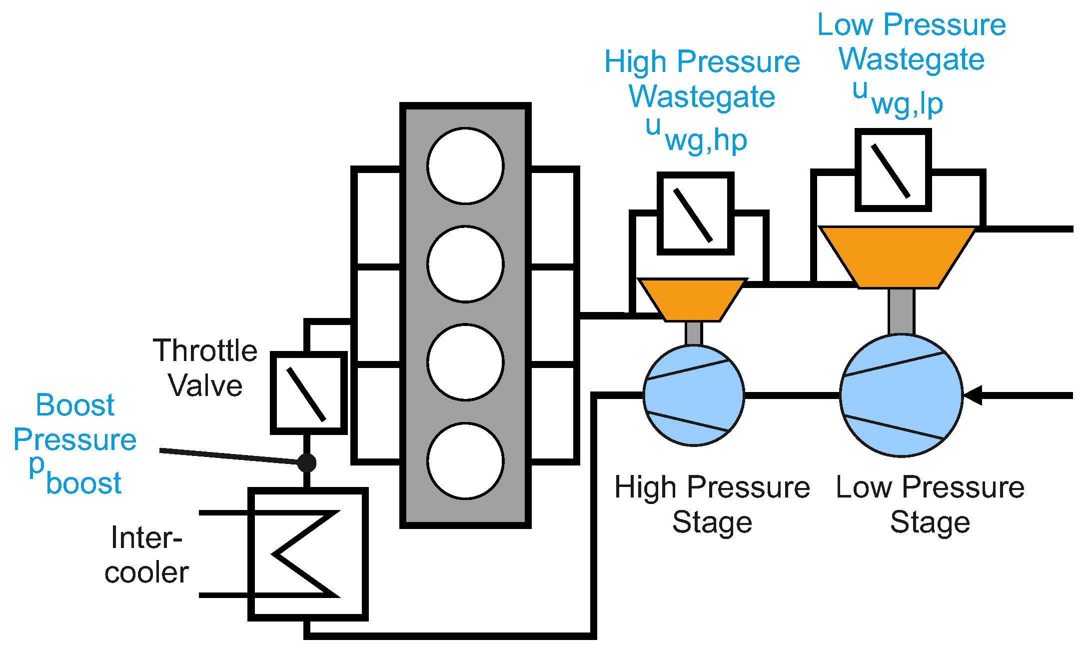
The schematic set-up of the investigated air path architecture is shown in Figure 1. This concept consists of two turbocharging stages that are placed in series. Each stage consists of a compressor and a turbine, which are connected by a common shaft. For experimental analysis of the system, the two-stage turbocharging architecture was built up and implemented in a demonstrator vehicle (Ford Focus) with a 1 . 8 l four-cylinder gasoline engine. More details on the experimental setup can be found in [23,26]. The experiments conducted in this paper have been recorded with this demonstrator vehicle. All experimental data from the present paper were gained at a vehicle dynamometer, which allows setting a constant engine speed.
The controlled variable of the system is the boost pressure p b o o s t (for a better overview, all variables and indices are summarized in the Appendix Section), which is measured with a pressure sensor, positioned behind the intercooler and in front of the throttle valve. In gasoline engines, a high exhaust gas temperature is present, which is the reason why the application of sensors and advanced actuators in the exhaust gas path is critical for a series production configuration. Thus, in the presented control approach, no sensor signals from the exhaust gas path are used for control purposes.
As actuators, wastegates on the high pressure ( u w g , h p ) and on the low pressure stage ( u w g , l p ) are used. In the investigated set-up, pneumatic actuators are applied, without any additional sensor, e.g., for position feedback. The wastegate actuation signals correspond to a pulse-width modulated (PWM) signal, which can be set between u w g , h p = [ 0 . . . 100 ] and u w g , l p = [ 0 . . . 100 ] . These allow manipulating the pilot pressure, which has influence on the cross-section diameter of the wastegate opening area. Thus, the amount of exhaust gas that passes the turbine or the wastegate can be adjusted. Low values, such as u w g = 0 , open the wastegate, and higher values, such as u w g = 100 , close the wastegate. With an open wastegate, the majority of the exhaust gas bypasses the turbine, whereas a fully-closed wastegate ensures that all of the exhaust gas flows through the turbine.
For the chosen control approach, the two wastegate PWM signals u w g , h p and u w g , l p are used as actuated variables, and p b o o s t is used as a controlled variable. Additionally, the engine speed n e n g and ambient pressure p a m b are used as measured variables; both values are available in a series production configuration. For the purpose of modeling and validation of the control algorithm, additional sensors are available in the car; however, they are not used in the control algorithm, such as the average exhaust gas back pressure p e x h . As nowadays usual in series applications, the throttle valve is fully open in boosted operating points to reduce fuel consumption. As a consequence, the boost pressure is equal to the intake manifold pressure.

2.2. Requirements on Control

The control algorithm needs to handle both turbocharger stages in a coordinated fashion, such that reference tracking for the boost pressure is made possible. Compared to diesel engines, gasoline engines pose higher demands on the control algorithm. Due to the quantitative control used as the working principle for gasoline engines, a fixed air-to-fuel ratio results, and thus, the torque is directly determined by the air path. Thereby, quick reference tracking has to be achieved without oscillations and without significant overshoots. Additionally, the control algorithm should respect the upper limit constraints for the high pressure and low pressure turbocharger speeds n t c , h p and n t c , l p , as exceeding these limits might damage the turbocharger. This becomes especially challenging, as the small high pressure stage is intentionally not designed for the complete engine operating range.

3. Analysis of Pumping Losses

As stated earlier, a desired boost pressure can be realized by different combinations of wastegate positions for the low and high pressure stage. Depending on how each pressure stage is used, the exhaust gas back pressure changes. The exhaust gas back pressure influences substantially the pumping losses and, thus, the efficiency and fuel consumption of the engine. In the following, the influencing factors for the exhaust gas back pressure are examined in the case of two-stage turbocharging. For the power of the compressor and the turbine at each stage ([5]), it holds:
P c , h p = m ˙ c , h p · c p · T u c , h p · 1 η s , c , h p Π c , h p κ a i r - 1 κ a i r - 1
P c , l p = m ˙ c , l p · c p · T a m b · 1 η s , c , l p Π c , l p κ a i r - 1 κ a i r - 1
P t , h p = m ˙ t , h p · c p · T u t , h p · η s , t , h p 1 - Π t , h p 1 - κ e x h κ e x h
P t , l p = m ˙ t , l p · c p · T u t , l p · η s , t , l p 1 - Π t , l p 1 - κ e x h κ e x h
where the pressure ratios are defined as Π c , h p = p d c , h p p u c , h p and Π t , h p = p u t , h p p d t , h p and accordingly for the low pressure stage. In the following formulas, friction is neglected. If we look at stationary operation, the following simplifications can be made: P c , h p = P t , h p and P c , l p = P t , l p , as well as m ˙ c , h p = m ˙ c , l p = m ˙ a s p , which leads to:
m ˙ t , h p · c p · T u t , h p · η s , t , h p · η s , c , h p 1 - Π t , h p 1 - κ e x h κ e x h = m ˙ a s p · c p · T u c , h p Π c , h p κ a i r - 1 κ a i r - 1
m ˙ t , l p · c p · T u t , l p · η s , t , l p · η s , c , l p 1 - Π t , l p 1 - κ e x h κ e x h = m ˙ a s p · c p · T a m b Π c , l p κ a i r - 1 κ a i r - 1
If additionally, the efficiency for the entire high pressure stage and for the entire low pressure stage is introduced as:
η t c , h p = η s , c , h p · η s , t , h p
η t c , l p = η s , c , l p · η s , t , l p
the pressure ratios can be expressed as:
Π c , h p = 1 + m ˙ t , h p T u t , h p m ˙ a s p T u c , h p η t c , h p 1 - Π t , h p 1 - κ e x h κ e x h κ a i r κ a i r - 1
Π c , l p = 1 + m ˙ t , l p T u t , l p m ˙ a s p T a m b η t c , l p 1 - Π t , l p 1 - κ e x h κ e x h κ a i r κ a i r - 1
For the boost pressure, it results:
p b o o s t = p a m b Π c , h p Π c , l p = p a m b 1 + m ˙ t , h p T u t , h p m ˙ a s p T u c , h p η t c , h p 1 - Π t , h p 1 - κ e x h κ e x h κ a i r 1 - κ a i r
· 1 + m ˙ t , l p T u t , l p m ˙ a s p T a m b η t c , l p 1 - Π t , l p 1 - κ e x h κ e x h κ a i r 1 - κ a i r
For stationary operation, the values ( p a m b , T a m b , m ˙ a s p ) become constant and are independent of the wastegate actuation; on top, it approximately holds that p d t , l p p a m b . We can conclude that for a given boost pressure, the exhaust gas back pressure especially depends on two significant parameters: the efficiency of each stage and the mass flows, which can be adjusted by the wastegates.
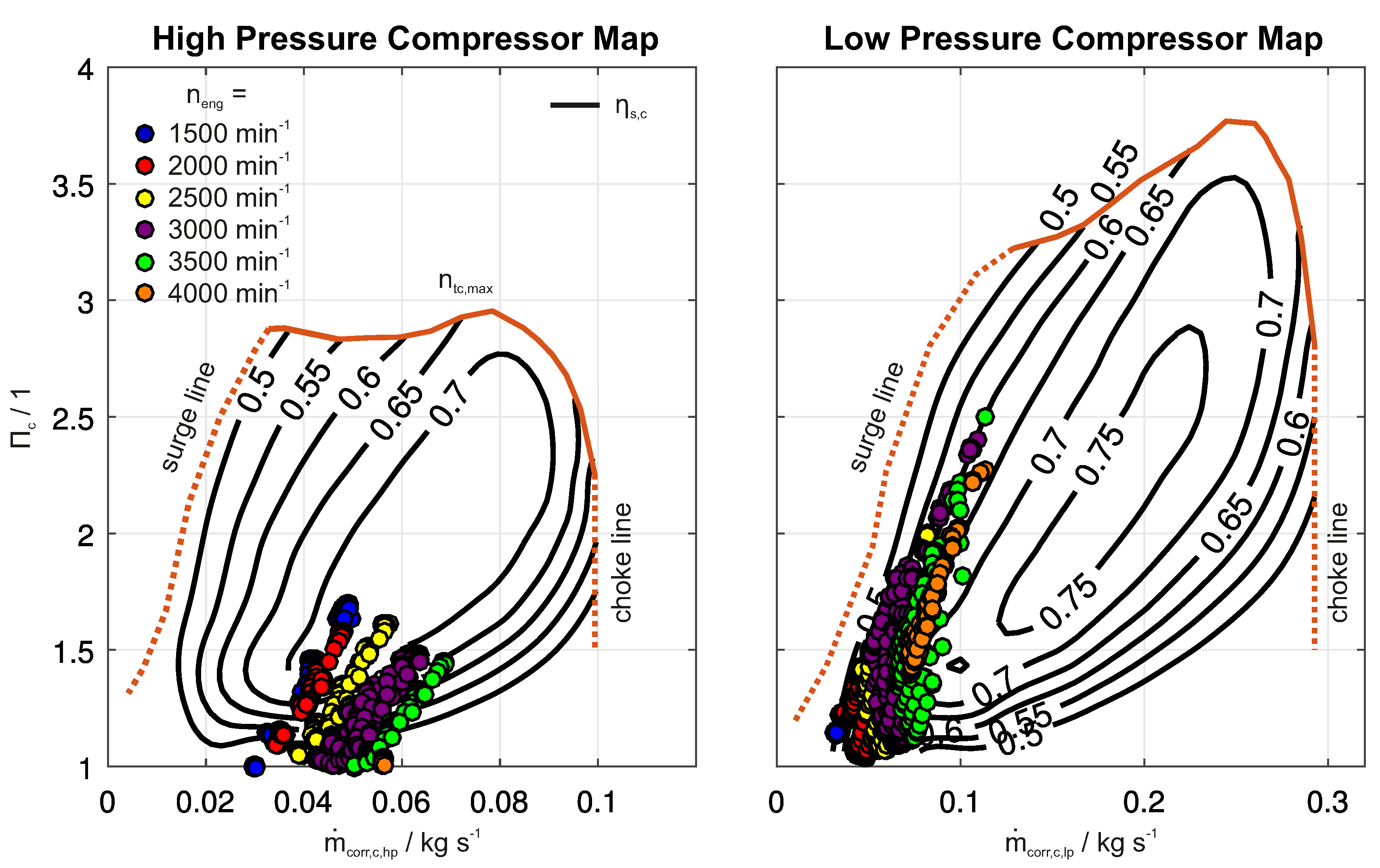
In the following, it is shown that the efficiencies depend significantly on the control strategy. For this purpose, experiments were conducted for evaluating the compressor efficiency at different operating points. The experimental results are shown in Figure 2. Different combinations of wastegate position in the ranges u l p , w g = [ 0 , 100 ] and u h p , w g = [ 0 , 60 ] were applied with the goal to measure the resulting pressure ratio at the compressor of each stage along with the resulting air mass flow. The values are then plotted in the compressor maps given by the manufacturer.
For the high pressure stage, we can see that at low engine speeds, high efficiency operation is possible. For high engine speeds, the efficiency of the high pressure stage decreases significantly as the operating points are shifted to higher mass flows and, therefore, to the right side of the map. At an engine speed of 4000 rpm, already, no pressure increase is possible due to the low efficiency. In case of the low pressure stage, the behavior is different. At low engine speeds, where small mass flows are present, the operating points are at the left side of the map. In this area, moderate efficiencies are reached. With higher engine speeds, the efficiency is increased. Looking at both stages, one can conclude that the control strategy influences the operating point of both turbochargers and, thus, impacts their efficiency.
In the following, the influence of the wastegate position on the pumping losses is examined. During the exhaust phase, the cylinder pressure is assumed to be equal to the exhaust gas back pressure p c y l = p e x h , whereas during the intake phase, the cylinder pressure can be assumed to be equal to the boost pressure p c y l = p b o o s t . The pumping loss can be calculated by:
W p = ( p e x h - p b o o s t ) V d i s
where V d i s is the displacement volume. In terms of a pumping loss mean effective pressure ( P M E P ), it results:
P M E P = p e x h - p b o o s t
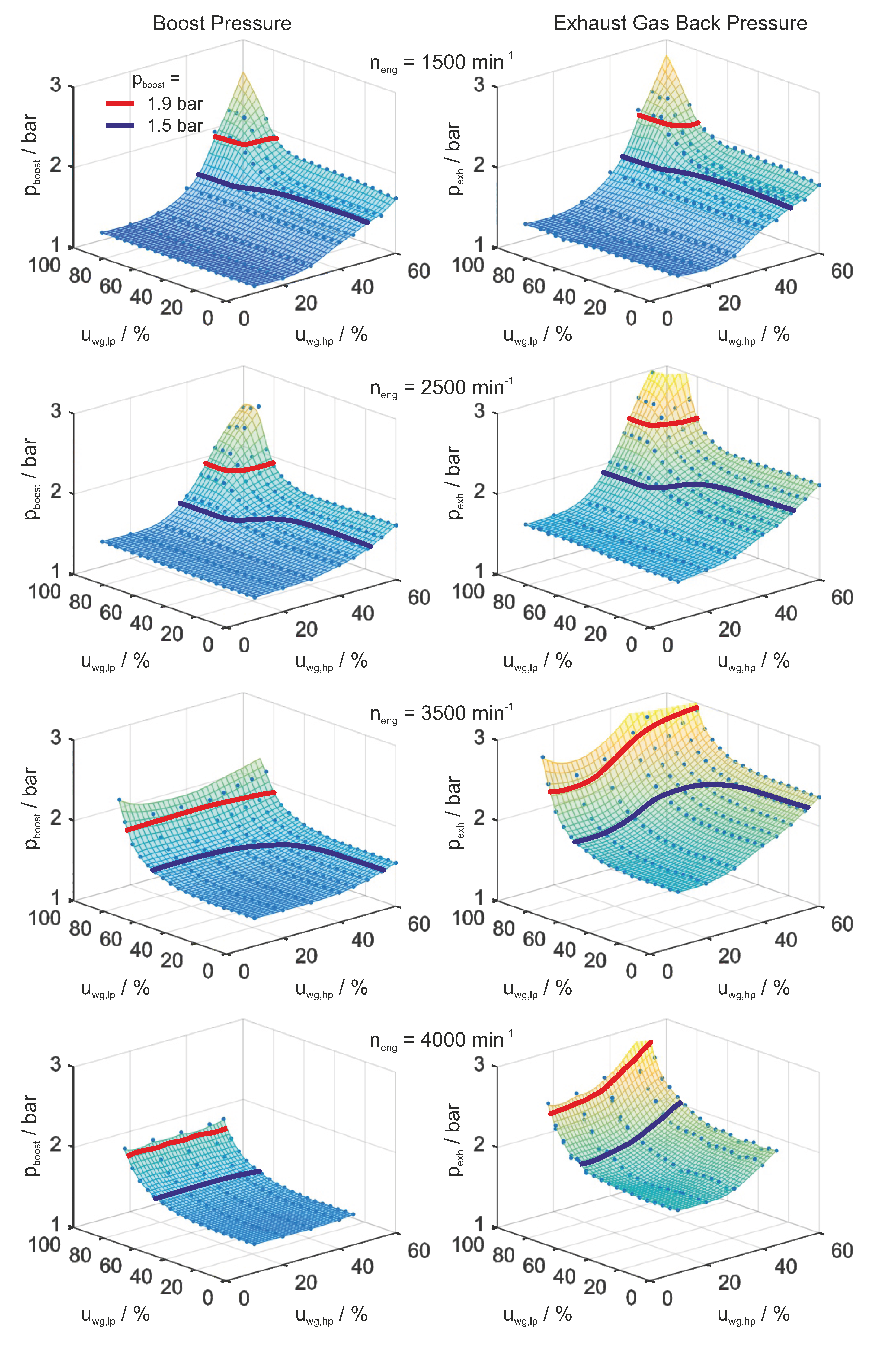
Thus, the pumping losses directly correlate with the difference of boost pressure and exhaust gas back pressure. In Figure 3, the resulting boost pressure and exhaust gas back pressure in dependence of the wastegate positions are shown.
For constant boost pressure, the pumping losses directly correlate to the exhaust gas back pressure. To show the dependence of the exhaust gas back pressure on the wastegate position, iso-curves are plotted for p b o o s t = 1 . 5 bar and p b o o s t = 1 . 9 bar. Using the measurements depicted in Figure 3 and following (13) and (14), for p b o o s t = 1 . 5 bar at an engine speed of n e n g = 3500 rpm, the pumping losses range from a minimum of 350 mbar, when u w g , h p = 0 , to a maximum of 730 mbar, when u w g , l p = 0 . At p b o o s t = 1 . 9 bar, the difference even ranges from 473 mbar to a maximum of 1034 mbar, depending on the wastegate position. This implies that choosing the correct control strategy can improve the P M E P by a delta of up to Δ P M E P = 561 mbar, which corresponds to approximately 3 kW. The experimental results show that for the purpose of reducing pumping losses, it is always best to choose the combination that is characterized by the maximum use of the low pressure turbocharging stage. This is realized by closing the low pressure wastegate and opening the high pressure wastegate as much as possible. Note: when only looking at Figure 2, it is not clear if this also holds true for small engine speeds. However, Figure 3 shows that this is valid for high, as well as for low engine speeds; although, in the case of low engine speeds, the difference in exhaust gas back pressure gets smaller.

4. Analysis of Transient Behavior

The two-stage turbocharging is used to improve the transient response behavior while at the same time allowing for high power outputs. For this reason, a high pressure stage is present, which allows a faster boost pressure increase due to the smaller polar mass moment of inertia J t c , h p and the significantly lower flow cross-sections of the compressor and turbine. On the other side, a bigger low pressure stage is present, which is slower with respect to the transient behavior due to the bigger polar mass moment of inertia J t c , l p . The increase in turbocharger speed is described by:
d d t 1 2 J t c , h p ω t c , h p 2 = P t , h p - P c , h p
d d t 1 2 J t c , l p ω t c , l p 2 = P t , l p - P c , l p
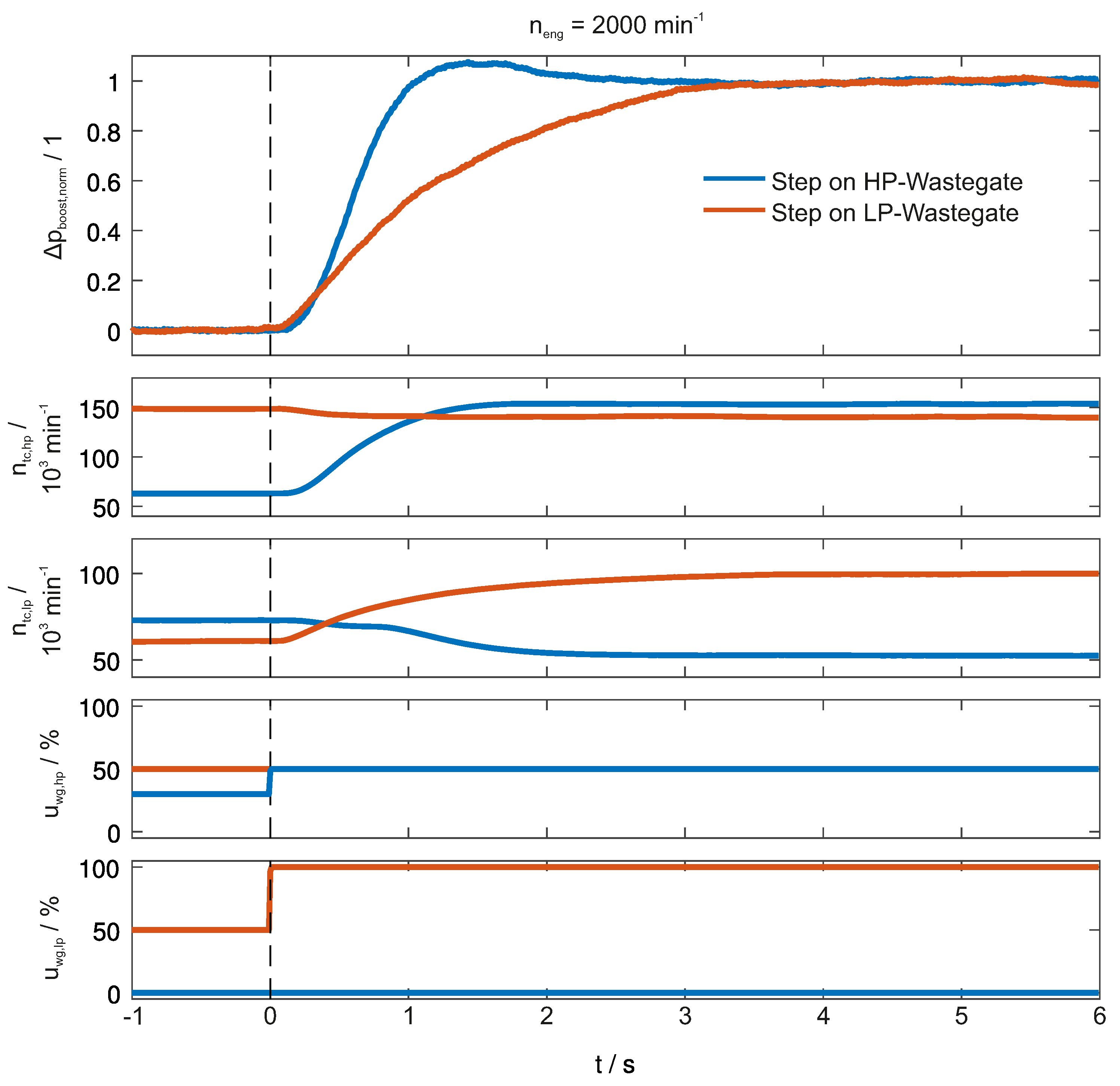
For the experimental analysis, the vehicle dynamometer was run at several constant engine speeds. At these engine speeds, different step inputs were applied on the two wastegates. As a considerable characteristic value, t 95 can be used, which describes the time until 95 % of the steady state value is reached for the first time. In Figure 4, an exemplary experimental result of the transient behavior of the high and low pressure stage is demonstrated. The plot shows a normalized expression of the boost pressure Δ p b o o s t , n o r m = ( p b o o s t - p b o o s t , l o w ) / ( p b o o s t , s s - p b o o s t , l o w ) , the rotational speed of the two turbochargers and the applied wastegate input signals. Each color corresponds to one independent measurement; in both cases, the step is applied at t = 0 s. When using the low pressure wastegate, the step response shows a characteristic time value of t 95 , l p = 2 . 8 s. In contrast to that, when using the high pressure wastegate, the value can be reduced to t 95 , h p = 1 s. As long as the high pressure stage is able to deliver torque, it holds true that for the entire investigated operating range, it is beneficial to use the high pressure stage from a transient point of view.

5. Comparison of Different Control Strategies

If the reduction of the pumping losses is the major requirement for control design, the low pressure stage should be used as much as possible. In contrast to that, if the major requirement is the transient behavior, the high pressure stage should be used as much as possible. For vehicle applications, both requirements are important; consequently, in the best case, the control strategy exploits the possibilities that the two-stage architecture offers by a coordinated control.
In this paper, an optimization-based control strategy as given by model predictive control (MPC) is investigated. An overview of MPC can be found in [27,28]. In this case, numerical optimization is used to solve an optimization problem. The results of the optimization are the optimal actuated values. A model of the process is used to predict the system states and outputs, which serves as the basis for the optimization task. The desired control behavior is translated into an appropriate cost function. The MPC routine offers the advantage that severe requirements can be incorporated. Among these are the consideration of complex nonlinear system dynamics, which is present for the air path structure investigated. Moreover, limits on system states and outputs can be considered. In the given application, the turbocharger speed limits can be respected.
In model-in-the-loop (MiL) environments, different control strategies can be developed and evaluated. Optimization-based control in MiL environments, where no real-time requirements are posed, has the advantage that the upper bound on control performance can be determined. This allows us to see how a good management of the two turbocharger stages looks like. In the following, three different control strategies are outlined; one where the pumping losses are reduced, one where the time for the transient maneuver is reduced and one where both objectives are considered.

5.1. Control for the Reduction of Pumping Losses

As stated earlier, the reduction of pumping losses can be achieved by the reduction of the high pressure stage usage. Therefore, the following cost function can be used:
J = j = 0 N c h y 1 ( k + j k ) - y 1 , r e f ( k ) T Q y 1 ( k + j k ) - y 1 , r e f ( k ) + u w g , h p ( k + j k ) T R L u w g , h p ( k + j k ) + S · ϵ ( k + j k )
such that:
0 = x i + 1 - ϕ x i , u i , j = 0 , , N c h
u m i n u ( k + j k ) u m a x , j = 0 , , N c h
y 2 ( k + j k ) n t c , h p , m a x + ϵ h p ( k + j k ) , j = 0 , , N c h
y 3 ( k + j k ) n t c , l p , m a x + ϵ l p ( k + j k ) , j = 0 , , N c h
0 ϵ h p ( k + j k ) , j = 0 , , N c h
0 ϵ l p ( k + j k ) , j = 0 , , N c h
In the given cost function, the two main objectives, being the reference tracking of the boost pressure and reducing the high pressure turbocharger usage, are represented by different terms. In the cost function, the deviation between the boost pressure and the reference value is taken into account with the first summand, weighted by the matrix Q . y 1 ( k + j | k ) corresponds to the boost pressure predicted for the time step k + j based on the information available at time step k. The second summand penalizes closing the high pressure wastegate, by the weighting matrix R L . Additionally, a slack variable ϵ is introduced, which allows the optimization algorithm to exceed the turbocharger speed limits at a cost scaled with S . This changes the speed limits (20) and (21) to soft constraints, ensuring the feasibility of the optimization problem. The remaining constraints are the dynamic model (18), the upper and lower limits of the actuated values (19) and a hard constraint on the slack variable (23). Note that in this case, a static control law results, which means that given a certain boost pressure setpoint, disturbance and measured variables, fixed static actuated values result, which are not adjusted during transient maneuvers.

5.2. Control for Optimal Transient Behavior

In the case of transient-optimal control, the high pressure stage should be used as much as possible, as the high pressure stage can quickly increase the boost pressure. The corresponding cost is given by:
J = j = 0 N c h y 1 ( k + j k ) - y 1 , r e f ( k ) T Q y 1 ( k + j k ) - y 1 , r e f ( k ) + S · ϵ ( k + j k )
such that
0 = x i + 1 - ϕ x i , u i , j = 0 , , N c h
u m i n u ( k + j k ) u m a x , j = 0 , , N c h
y 2 ( k + j k ) n t c , h p , m a x + ϵ h p ( k + j k ) , j = 0 , , N c h
y 3 ( k + j k ) n t c , l p , m a x + ϵ l p ( k + j k ) , j = 0 , , N c h
0 ϵ h p ( k + j k ) , j = 0 , , N c h
0 ϵ l p ( k + j k ) , j = 0 , , N c h
In this case, the same constraints are used as in the case of reducing pumping losses. However, the cost function only takes into account the deviation of the predicted boost pressure to the setpoint and the slack variables, being represented by the different summands, respectively. The use of wastegate signals is not penalized, which allows the controller to directly optimize for fast transient behavior.

5.3. Multi-Objective Control

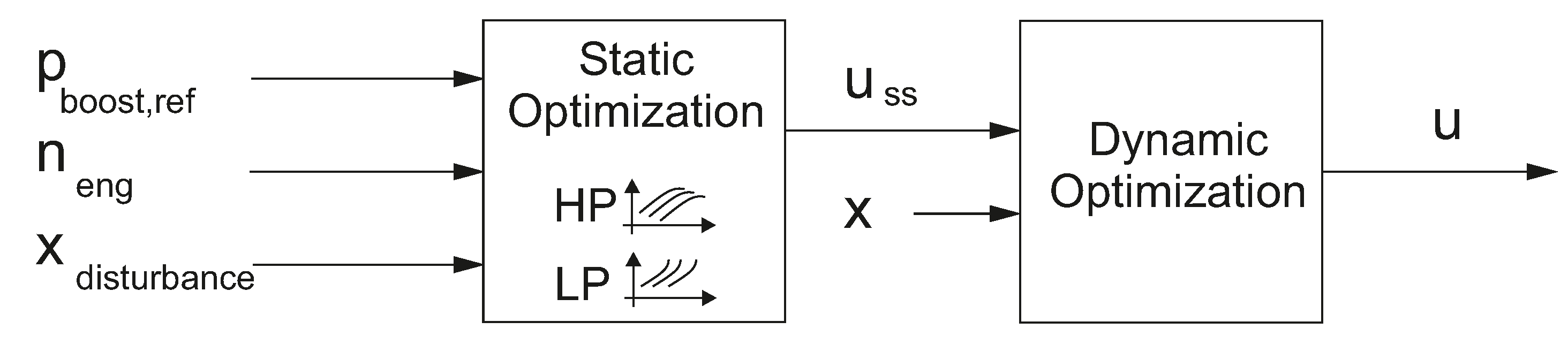
So far control settings were discussed where either fast transient response or efficient operation was accounted for. In the following, a control concept is investigated that takes the trade-off between both criteria, fast transient response and high efficient steady state operation into account. The objective is to use the high pressure stage to get as quick as possible to the boost pressure setpoint and then decrease the high pressure and increase the low pressure wastegate to reduce pumping losses in stationary operation. For this reason, a combination of the two aforementioned approaches is derived. In Figure 5, the scheme of the control algorithm is presented. The first optimization calculates the optimal steady state values for the actuated variables u S S , depending on the boost pressure setpoint, the disturbance and measured variables. The cost function and constraints are equal to (17)–(23). These optimal steady state values are then used as additional reference inputs for a second dynamic optimization. The results of the dynamic optimization are the actuated values, which are output to the plant. Note: The first optimization is static and could therefore alternatively be calculated offline and substituted by lookup tables. This would reduce the computational effort of the control algorithm. As the focus was set on exploiting the optimal management of the turbocharging stages rather than real-time capability, optimization was also used for the steady state calculation.
The cost function, which is used for the dynamic optimization, is given as follows:
J = j = 0 N c h y 1 ( k + j k ) - y 1 , r e f ( k ) T Q y 1 ( k + j k ) - y 1 , r e f ( k ) + Δ u ( k + j k ) T R D Δ u ( k + j k ) + u ( k + j k ) - u S S ( k ) T R S S u ( k + j k ) - u S S ( k ) + S · ϵ ( k + j k )
such that:
0 = x i + 1 - ϕ x i , u i , j = 0 , , N c h
u M i n u ( k + j k ) u M a x , j = 0 , , N c h
y 2 ( k + j k ) n t c , h p , m a x + ϵ h p ( k + j k ) , j = 0 , , N c h
y 3 ( k + j k ) n t c , l p , m a x + ϵ l p ( k + j k ) , j = 0 , , N c h
0 ϵ h p ( k + j k ) , j = 0 , , N c h
0 ϵ l p ( k + j k ) , j = 0 , , N c h
The constraints in this formulation are the same as in the two previous cases. However, in the cost function, there are additional summands. The first term considers the deviation from the reference value, weighted by matrix Q . Second, the rate change of the actuated values, Δ u ( k + j k ) = u ( k + j k ) - u ( k + j - 1 k ) , is penalized. The deviation from the optimized steady state actuated values u s s is represented by the third term, while the final summand shows the slack variables. This cost function allows the usage of the high pressure stage during transient maneuvers to quickly reach the requested boost pressure and leads to an increased use of the low pressure wastegate in stationary operation.

5.4. Simulative Comparison of Control Strategies

A model of the process is needed for simulating the plant. The fundamental equations for air path modeling can be found in [29]. A way to reduce the arising model dimension is the application of singular perturbation methods [30,31]. In such a way, the given setup was modeled by a DAE model resulting in two differential and two algebraic states; details can be found in [25]. The arising model was validated against measurement data, which shows that the model can reproduce the dynamic and static behavior of the air path structure. To test the different control strategies in a closed-loop setting, the model and the different control strategies were implemented in a MATLAB/Simulink environment. The model for the optimization-based controller is the same as the plant model. This has the advantage that the different control strategies can be evaluated without the influence of model-mismatch according to the focus of the present paper.
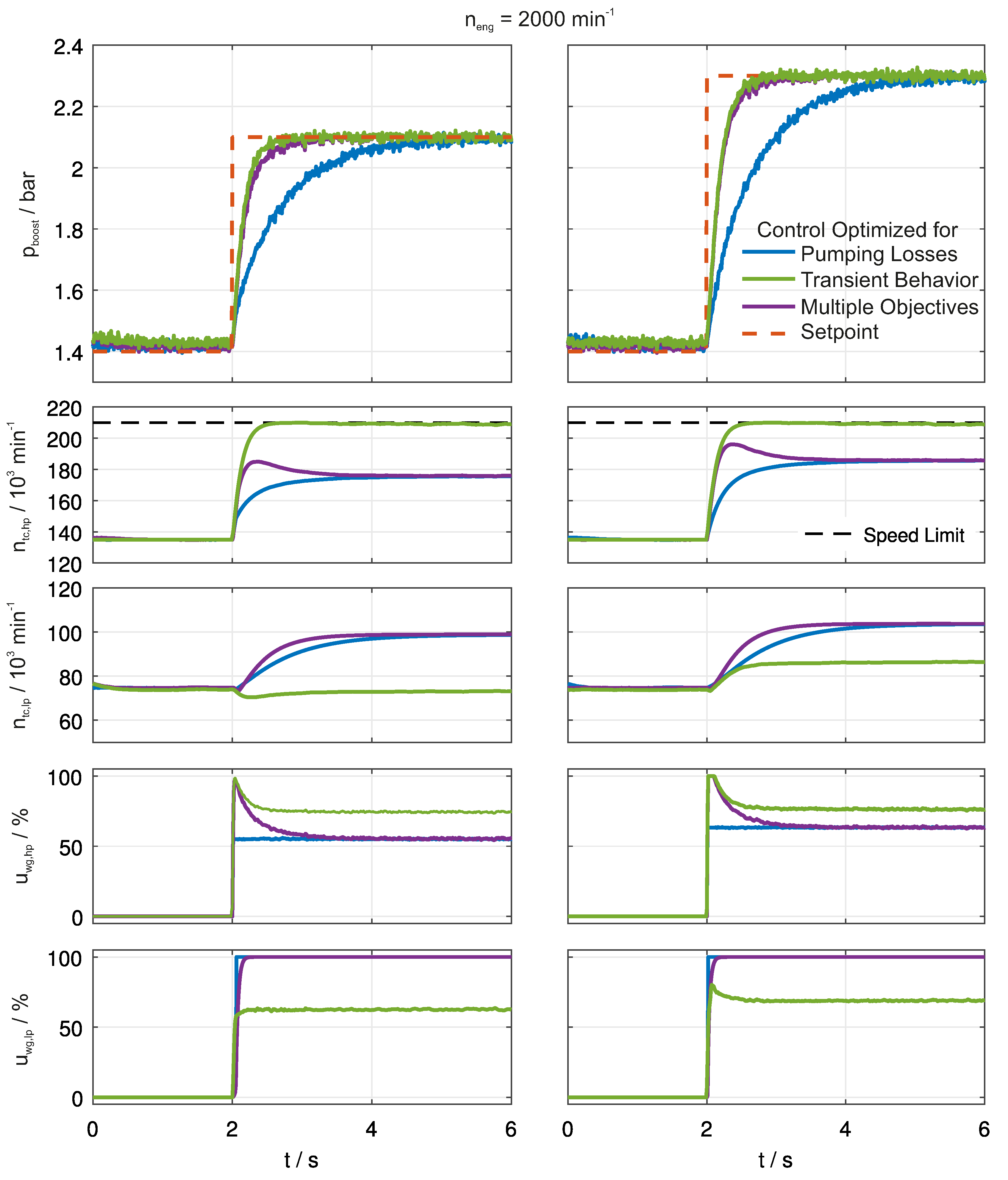
In Figure 6, the resulting closed-loop control results are depicted for two step inputs for the reference signal with different step heights. The controller, which reduces pumping losses, entirely relies on the optimal steady state actuation values, which allow tracking the given reference. Moreover, it is the control strategy that uses the low pressure stage in a maximum way. As a consequence, the goal to reduce pumping losses is realized. For the controller, which improves the transient dynamics, the high pressure stage is used as much as possible. The upper limit is restricted by the maximum turbocharger speed. In comparison to the first controller, this strategy reaches the boost pressure setpoint much quicker; however, it uses the low pressure stage less, which results in higher pumping losses. The third strategy is the multi-objective controller. In this case, the actuated values correspond to the ones used by the time-optimal controller during the transient phase. Afterwards, the actuated values fade over towards the optimal steady state values, which are also used by the controller, which reduces the pumping losses. This results in a fast transient response, which is comparable to the time-optimal one. At the same time, the pumping losses are reduced by fading over to the solution with maximum low pressure usage.
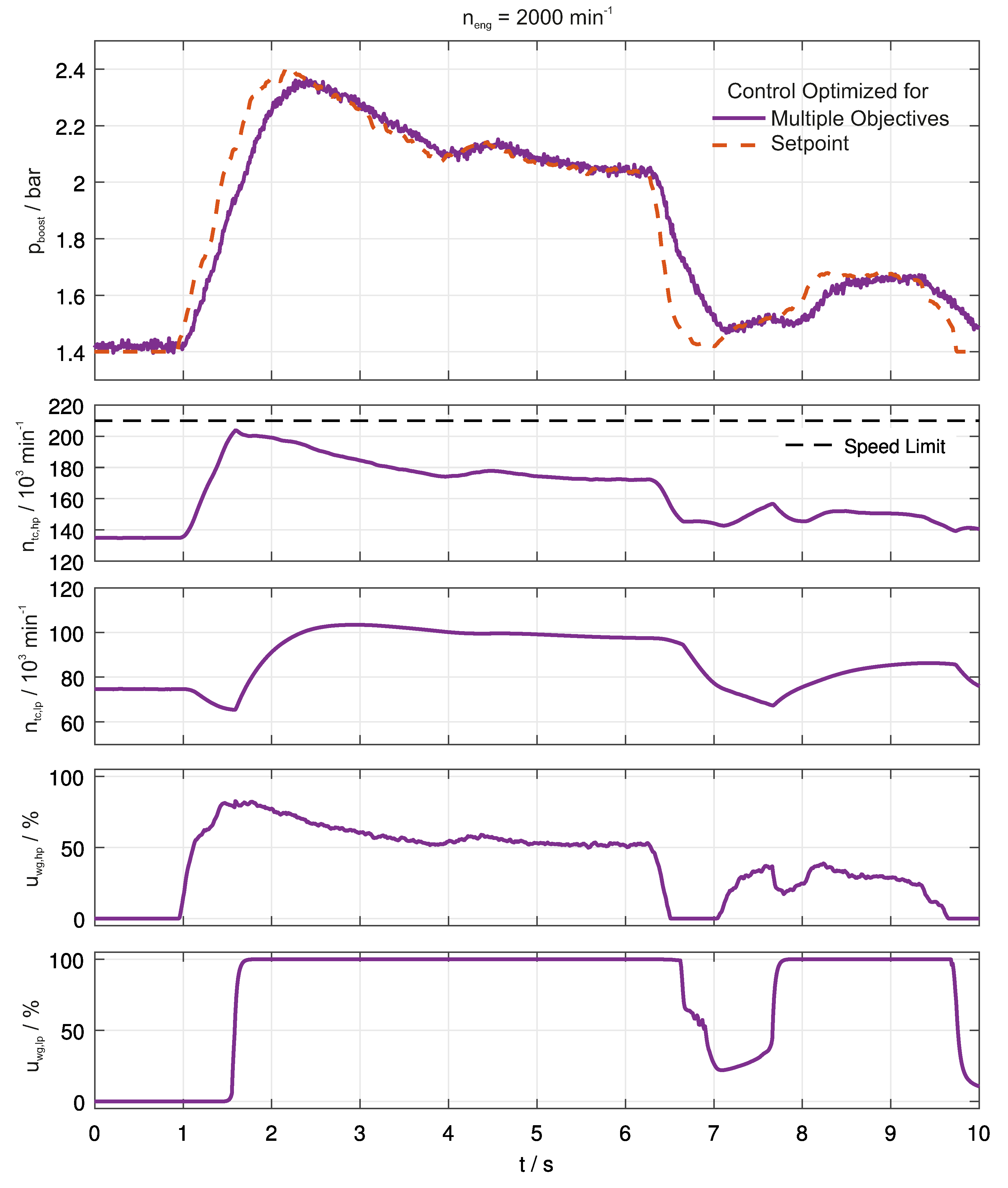
In Figure 7, we can see moreover that the multi-objective control strategy is also able to track arbitrary reference signals. The given setpoint profile was recorded in a vehicle and, thus, represents an exemplary profile for vehicle acceleration. For the given reference signal, the speed limits of the turbochargers are respected. At the same time, the reference is tracked with high control quality, taking into account a fast transient rise, as well as reducing pumping losses by using the low pressure stage.

6. Conclusions

Increasingly complex air path structures are used to further reduce fuel consumption and to improve the transient behavior. One promising architecture is the two-stage turbocharging, which represents an over-actuated system. Two different input signals are present for controlling one variable, the boost pressure. In this paper, the resulting degrees of freedom are examined. The effect of the high pressure and low pressure wastegate on the pumping losses and on the transient behavior is investigated. For these two objectives, the control strategies are contradicting. In order to reduce pumping losses, the low pressure stage should be used as much as possible, whereas for a fast transient maneuver, the high pressure stage should be used as much as possible. Based on these findings, a control strategy is developed in this paper to cope with both requirements. The idea is to use the high pressure stage in the transients while fading over to the use of low pressure stage for stationary operation. This control strategy is realized by defining a specific control formulation for an optimization-based controller. First, the optimal steady state actuated values are determined, which are then used as input for a dynamic optimization. The resulting controller is able to provide a fast boost pressure build up and at the same time a reduction of pumping losses for steady state operation.

Acknowledgments

This research was performed as part of the Research Unit (Forschergruppe) FOR 2401 “Optimization based Multiscale Control for Low Temperature Combustion Engines”, which is funded by the German Research Association (Deutsche Forschungsgemeinschaft, DFG). The support is gratefully acknowledged.

Author Contributions

Thivaharan Albin wrote the paper, performed the development of the control laws and did the simulative evaluation of these control laws. Dennis Ritter conceived and analyzed the vehicle experiments. Norman Liberda set up the vehicle and conducted the vehicle experiments. Dirk Abel is the senior project leader.

Conflicts of Interest

The authors declare no conflict of interest.

Abbreviations

The following abbreviations are used in this manuscript:
n
Engine speed
ω
Rotational speed
m ˙
Mass flow
P
Power
P M E P
Pumping loss mean effective pressure
p
Pressure
Π
Pressure ratio
T
Temperature
J
Polar mass moment of inertia
t
Time
k
Discrete time point
V
Volume
W
Work
ϵ
Slack variable
Q , R , S
Weighting matrices
η
Efficiency
κ
Isentropic exponent
c p
Specific isobaric heat capacity
u
Control input
x
Differential state variable
y
System output
t
Turbine
c
Compressor
c y l
Cylinder
h p
High pressure stage
l p
Low pressure stage
t c
Turbocharger
c h
Control horizon
s
Isentropic
c o r r
Corrected
n o r m
Normalized
d i s
Displacement
u c
Upstream compressor
d c
Downstream compressor
u t
Upstream turbine
d t
Downstream turbine
a m b
Ambient conditions
e n g
Engine
a s p
Aspirated
p
Pumping
a i r
Air
e x h
Exhaust gas
b o o s t
Boost
w g
Wastegate
r e f
Reference
k
Discrete time step
k + j | k
Prediction for time step k + j based on the information available at time step k
L
Low pressure
D
Dynamic
s s
Steady state

References

  1. Payri, F.; Luján, J.; Guardiola, C.; Pla, B. A challenging future for the IC engine: New technologies and the control role. Oil Gas Sci. Technol. 2014, 70, 15–30. [Google Scholar] [CrossRef]
  2. Eriksson, L.; Nielsen, L. Modeling and Control of Engines and Drivelines; John Wiley & Sons: Hoboken, NJ, USA, 2014. [Google Scholar]
  3. Baines, N.C. Fundamentals of turbocharging. Gas 2005, 2014, 3–4. [Google Scholar]
  4. Heywood, J.B. Internal Combustion Engine Fundamentals; Mcgraw-Hill: New York, NY, USA, 1988. [Google Scholar]
  5. Guzzella, L.; Onder, C. Introduction To Modelling and Control Of Internal Combustion Engine Systems; Springer: Berlin/Heidelberg, Germany, 2004. [Google Scholar]
  6. Wang, J. Hybrid robust air-path control for diesel engines operating conventional and low temperature combustion modes. IEEE Trans. Control Syst. Technol. 2008, 6, 1138–1151. [Google Scholar] [CrossRef]
  7. Drews, P.; Hoffmann, K.; Beck, R.; Gasper, R.; Vanegas, A.; Felsch, C.; Peters, N.; Abel, D. Fast model predictive control for the air path of a turbocharged diesel engine. In Proceedings of the European Control Conference, Budapest, Hungary, 23–26 August 2009; pp. 3377–3382.
  8. Murilo, A.; Alamir, M.; Alberer, D. A general NMPC framework for a diesel engine air path. Int. J. Control 2014, 87, 2194–2207. [Google Scholar] [CrossRef]
  9. Huang, M.; Nakada, H.; Butts, K.; Kolmanovsky, I. Nonlinear model predictive control of a diesel engine air path: A comparison of constraint handling and computational strategies. IFAC Pap. OnLine 2015, 48, 372–379. [Google Scholar] [CrossRef]
  10. Alfieri, V.; Conte, G.; Pedicini, C. Feedback linearization control for the air & charging system in a diesel engine. In Proceedings of the European Control Conference, Linz, Austria, 15–17 July 2015; pp. 2565–2570.
  11. Moulin, P.; Chauvin, J. Modelling and control of the air system of a turbocharged gasoline engine. J. Control Eng. Pract. Control 2011, 19, 287–297. [Google Scholar] [CrossRef]
  12. El Hadef, J.; Olaru, S.; Rodriguez-Ayerbe, P.; Colin, G.; Chamaillard, Y.; Talon, V. Explicit nonlinear model predictive control of the air path of a turbocharged spark-ignited engine. In Proceedings of the International Conference on Control Applications (CCA), Hyderabad, India, 28–30 August 2013; pp. 71–77.
  13. El Hadef, J.; Olaru, S.; Rodriguez-Ayerbe, P.; Colin, G.; Chamaillard, Y.; Talon, V. Nonlinear model predictive control of the air path of a turbocharged gasoline engine using Laguerre functions. In Proceedings of the Conference on System Theory, Control and Computing (ICSTCC), Sinaia, Romania, 11–13 October 2013; pp. 193–200.
  14. Li, Y.; Zhou, X.; Hu, Y.; Chen, H. Air path system control of turbocharged gasoline engine based on fuzzy PID. In Proceedings of the Chinese Control and Decision Conference (CCDC), Qingdao, China, 23–25 May 2015; pp. 941–946.
  15. Zhou, X.; Gong, X.; Hu, Y.; Chen, H. Modeling and control of the air path system in turbocharged gasoline engine. In Proceedings of the Chinese Control and Decision Conference (CCDC), Qingdao, China, 23–25 May 2015; pp. 3469–3474.
  16. Moulin, P.; Grondin, O.; Fontvieille, L. Control of a two stage turbocharger on a Diesel Engine. In Proceedings of the Joint 48th IEEE Conference on Decision and Control and 28th Chinese Control Conference, Shanghai, China, 16–18 December 2009; pp. 5200–5206.
  17. Moulin, P. Air Systems Modeling and Control for Turbocharged Engines. Ph.D. Thesis, École Nationale Supérieure des Mines de Paris, Paris, France, 2010. [Google Scholar]
  18. Moulin, P.; Grondin, O. Control design for a second order dynamic system: Two-stage turbocharger. Proc. Adv. Autom. Control 2013, 46, 460–466. [Google Scholar] [CrossRef]
  19. Hall, D.I.W.; Nefischer, P.; Hiemesch, D.I.D. Der neue zweistufig aufgeladene Sechszylinder-Dieselmotor im BMW 740d. MTZ Motortech. Z. 2010, 71, 224–233. [Google Scholar]
  20. Dickinson, P.; Glover, K.; Collings, N.; Yamashita, Y.; Yashiro, Y.; Hoshi, T. Real-time control of a two-stage serial VGT Diesel engine using MPC. IFAC Pap. OnLine 2015, 48, 117–123. [Google Scholar] [CrossRef]
  21. Kotman, P.; Bitzer, M.; Kugi, A. Flatness-based feedforward control of a two-stage turbocharged diesel air system with EGR. In Proceedings of the IEEE International Conference on Control Applications, Yokohama, Japan, 8–10 September 2010; pp. 979–984.
  22. Schwarzmann, D.; Nitsche, R.; Lunze, J. Modelling of the air-system of a two-stage turbocharged passenger car diesel engine. In Proceedings of the 5th Mathematical Modelling (MATHMOD), Vienna, Austria, 7–10 February 2006.
  23. Glück, S. Charging Concepts for a two-stage Turbocharging Gasoline Engine. Ph.D. Thesis, RWTH Aachen University, Aachen, Germany, 2013. [Google Scholar]
  24. Albin, T.; Ritter, D.; Liberda, N.; Pischinger, S.; Abel, D. Two-Stage Turbocharged Gasoline Engines: Experimental Validation of Model-based Control. IFAC Pap. OnLine 2015, 48, 124–131. [Google Scholar] [CrossRef]
  25. Albin, T.; Ritter, D.; Abel, D.; Liberda, N.; Quirynen, R.; Diehl, M. Nonlinear MPC for a two-stage turbocharged gasoline engine airpath. In Procedings of the Conference on Decision and Control (CDC), Osaka, Japan, 15–18 December 2015.
  26. Buchner, F.; Wedowski, S.; Sehr, A.; Gluck, S.; Schernus, C. In-vehicle optimization of 2-stage turbocharging for gasoline engines. Int. J. Autom. Eng. 2011, 2, 143–148. [Google Scholar]
  27. Camacho, E.F.; Alba, C.B. Model Predictive Control; Springer Science & Business Media: Berlin/Heidelberg, Germany, 2013. [Google Scholar]
  28. Rawlings, J.; Mayne, D. Model Predictive Control: Theory and Design; Nob Hill Publishing: Madison, USA, 2009. [Google Scholar]
  29. Eriksson, L. Modeling and control of turbocharged SI and DI engines. Oil & Gas Science and Technology-Revue de l’IFP 2007, 62, 523–538. [Google Scholar]
  30. Sharma, R.; Nešić, D.; Manzie, C. Model reduction of turbocharged (TC) spark ignition (SI) engines. IEEE Trans. Control Syst. Technol. 2011, 19, 297–310. [Google Scholar] [CrossRef]
  31. Khalil, H.; Grizzle, J. Nonlinear Systems; Prentice Hall: Upper Saddle River, NJ, USA, 1996; Volume 3. [Google Scholar]
Figure 1. Physical system overview of the investigated two-stage turbocharging concept.
Energies 09 00530 g001
Figure 2. Compressor operating points of the low pressure and high pressure stage at different engine speeds and wastegate combinations along with efficiency.
Energies 09 00530 g002
Figure 3. Maps with boost pressure and exhaust gas back pressure for different engine speeds with iso-curves on p b o o s t .
Energies 09 00530 g003
Figure 4. Comparison of transient behavior for the step input on low pressure wastegate u l p , w g and on high pressure wastegate u h p , w g .
Energies 09 00530 g004
Figure 5. Control scheme for the multi-objective optimization.
Energies 09 00530 g005
Figure 6. Closed-loop simulations. Comparison of the control strategy: (1) reduction of pumping losses; (2) fast response; (3) multi-objective.
Energies 09 00530 g006
Figure 7. Closed-loop simulations: multi-objective control strategy for a real setpoint profile.
Energies 09 00530 g007

