Article

Dynamic Energy Management of Hybrid Energy Storage Systems with a Hierarchical Structure

State Key Laboratory of Advanced Electromagnetic Engineering and Technology, Huazhong University of Science and Technology, 1037 Luoyu Road, Wuhan 430074, China
*
Author to whom correspondence should be addressed.
Energies 2016, 9(6), 395; https://doi.org/10.3390/en9060395
Submission received: 31 January 2016 / Revised: 27 March 2016 / Accepted: 11 May 2016 / Published: 24 May 2016
(This article belongs to the Special Issue Energy Efficient Actuators and Systems)

Abstract

:
In power system control unicontrol with single storage units or centralized control with multiple storage units to meet different level targets is challenging. Considering the charge and discharge characteristics of storage devices, this paper proposes a hierarchical configuration structure of a battery and supercapacitor mixed storage scenario, and develops a convenient control method for accessing various DC loads and can central manage mass batteries in one place. Aiming at the optimal management of large scale battery storage, the paper proposes a three-layer battery hierarchical control structure and the control objects and control circuits are discussed. Simulation studies are used to verify the control effect of the hierarchical storage system and the results show that the strategy can effectively decrease photovoltaic output fluctuation.

Graphical Abstract

1. Introduction

As the cost is continuously decreasing, photovoltaic (PV) generation has become one of the most important renewable energy sources and is being widely used. Grid-connected solar photovoltaic power plants are being installed globally at a fast pace. However, for present photovoltaic power technologies, the output power depends upon the availability of illumination and therefore may not always be constant. Problems brought by photovoltaics to the security stabilization and control of power grids are progressively appearing [1], especially when high permeability photovoltaics are accessed in a system. Additional regulations and standards are expected to be imposed.
A possible solution for regulating the natural oscillating output power of photovoltaics is to integrate them with an energy storage system [2]. Through a reasonable energy storage control strategy, the charge and discharge of energy storage can be controlled dynamically, which will make it possible to balance the energy of power grids and optimize system operation [3,4]. Used as an emergency power supply and energy buffer device, energy storage can not only balance photovoltaic output fluctuation, but also improve photovoltaic capacity permeability and utilization level, optimize the power grid economics, and improve the stability of the entire photovoltaic system [5]. Reasonable storage configurations and control strategies are therefore of great significance for photovoltaic and energy-storage hybrid systems in high photovoltaic penetration scenarios.
At present, most research on photovoltaic and energy-storage hybrid system focuses on predictive techniques, and control methods for modular converters and voltage regulators [6,7,8,9]. Control strategies of different time scales are also taken into consideration [10]. Some researchers have studied storage charge and discharge control strategies based on hybrid energy storage. Tummuru proposed a fast acting DC-link voltage-based energy management schemes for a hybrid energy storage system (HES) fed by solar photovoltaic (PV) energy. Using the proposed control schemes, fast DC-link voltage, effective energy management and reduced current stress on batteries are achieved [11]. Feng proposed a HES composed of lithium-ion batteries and supercapacitors that can be incorporated in the PV-based system to complement the supply-demand mismatches by using a multimode fuzzy-logic power allocator [12]. Ciobotaru proposed a power management strategy of a hybrid energy storage system (HESS) to reduce the required power rating of the supercapacitor bank (SCB) to only one-fifth of the vanadium redox battery (VRB) rating and to avoid the operation of the VRB at low power levels [13].
Based on the aforementioned review of previous works, it can be found that most research only considers the control effect of each storage device or hybrid storage in a centralized structure, and little work has been done to study the configuration pattern of different energy storage systems. Configuring different energy storages reasonably and hierarchical control strategies still need further study.
This paper proposes an energy management strategy based on a hierarchical storage structure. Based on the equivalent circuit models of PV, battery and supercapacitor, the paper introduces a typical distribution network structure with hierarchical storage, and then analyzes the control effect of batteries and supercapacitors. An improved configuration structure is proposed and its control method when some constraint conditions are taken into account is discussed. What’s more, to solve the problem brought by centralized management of mass batteries, a three-layer management structure is introduced. Finally, simulation is carried out to verify the control effect.

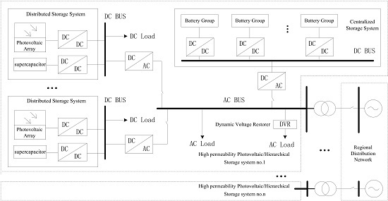
2. System Description and Modeling

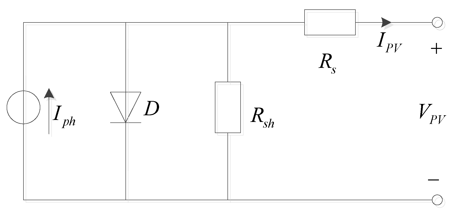
2.1. PV System Modeling

Commonly, PV plants use silicon solar cells, which equivalent circuit is shown in Figure 1 where Iph is the current of a photo-generated current source, D is a non-linear diode, Rsh and Rs are the internal parallel and series resistance. respectively, IPV is the photovoltaic output current, VPV is the photovoltaic output voltage. The volt-ampere characteristic equation is then:
I P V = I p h I s ( e q ( V P V + I R s ) A k T P V 1 ) V P V + I P V R s R s h
where Is is the diode saturation current, q is a constant ( 1.602 × 10 19 C ), k is the Boltzmann constant ( 1.381 × 10 23 J / K ), T P V is absolute temperature when the photovoltaic works, A is a diode feature fitting coefficient.
The photogenerated current is a function of light intensity and PV battery temperature, and it can be described as:
I p h = ( S S r e f ) [ I p h , r e f + C T ( T T r e f ) ]
where S is the actual irradiance, Sref is the irradiance under standard conditions, Tref is the absolute temperature when the photovoltaic works under standard conditions, CT is the temperature coefficient, and Iph,ref is the photogenerated current under standard conditions.

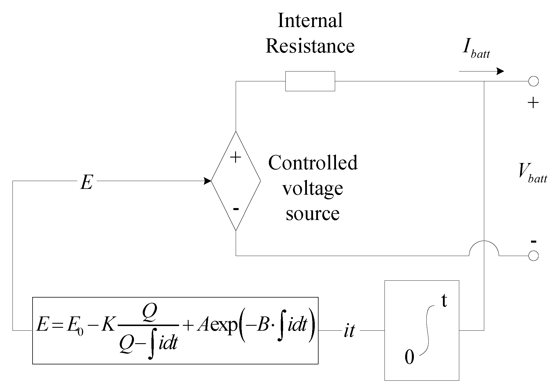
2.2. Storage Battery Modeling

The storage battery introduces a non-linear model, which uses a simple controlled voltage source in series with a constant resistance, as shown in Figure 2.
The model assumes the same characteristics for the charge and the discharge cycles. The open voltage source is calculated with a non-linear equation based on the actual SOC of the battery. The controlled voltage source is described as:
E = E 0 K Q Q i d t + A exp ( B i d t )
where E is the no-load voltage, E0 is the battery constant voltage, K is the polarisation voltage, Q is the battery capacity, i d t is the actual battery charge, A is the exponential zone amplitude, B is the inverse exponential zone time constant.
This model represents a non-linear voltage which depends solely on the actual battery charge. It means that when the battery is almost completely discharged and no current is flowing, the voltage will be nearly 0. This model yields accurate results and also represents the behaviour of the battery.

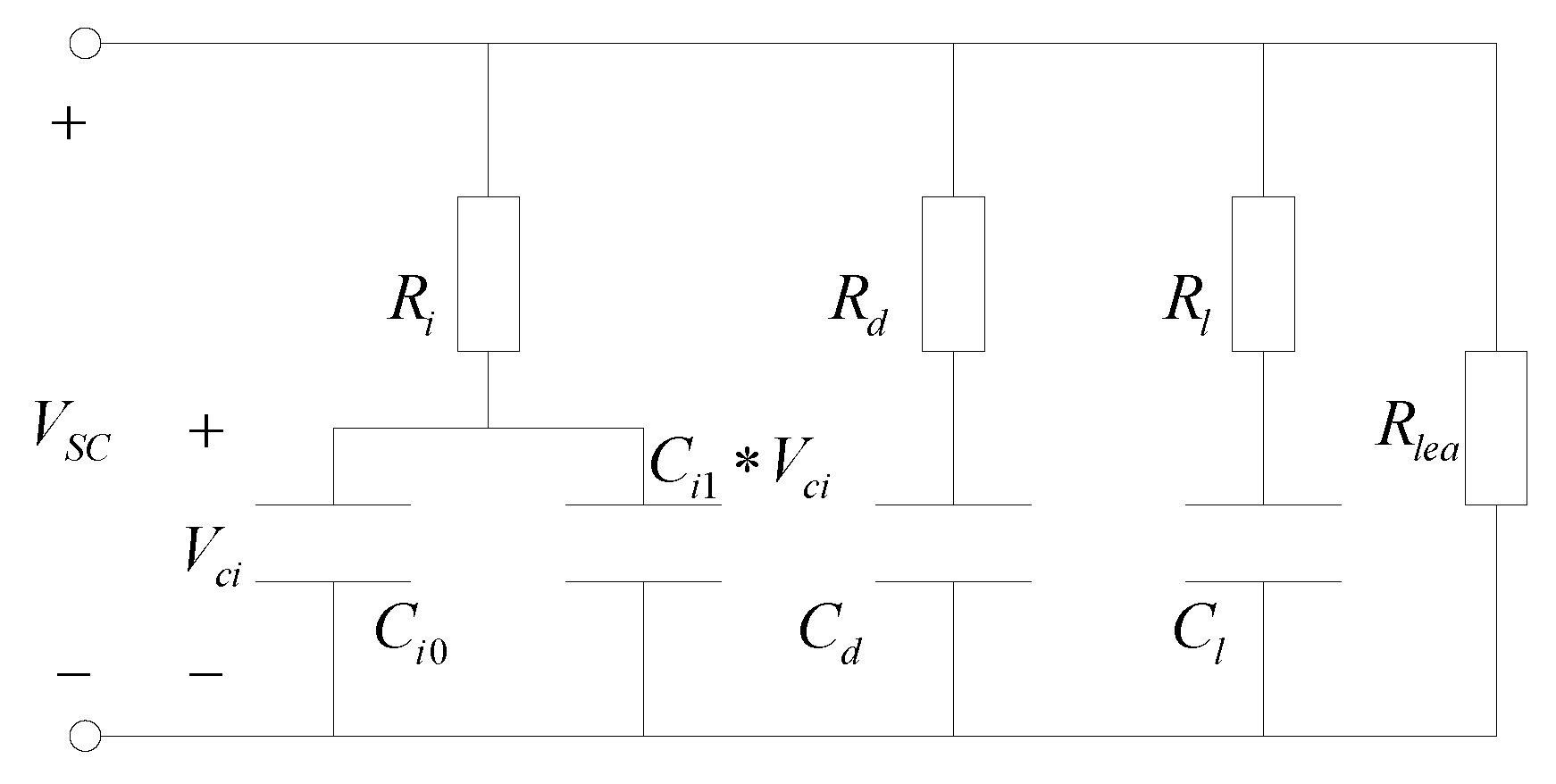
2.3. Supercapacitor Modeling

The supercapacitor considered in this paper is double-layer capacitor, its equivalent model circuit is shown in Figure 3. This model provides three different time constants to model the different charge transfers, which provides sufficient accuracy to describe the terminal behaviour of the supercapacitor for the desired span of 30 min.
To reflect the voltage dependence of the capacitance, the first branch is modelled as a voltage dependent differential capacitor. The differential capacitor consists of a fixed capacitance Ci0 and a voltage dependent capacitor Ci1 × Vci. A resistor, parallel to the terminals, is added to represent the self-discharge property. The first or immediate branch, with the elements Ri, Ci0 and the voltage dependent capacitance Ci1 in [F/V], dominates the immediate behaviour of the supercapacitor in the time range of seconds in response to a charge action. The second or delayed branch, with parameters Rd and Cd, dominates the behaviour in the range of minutes. Finally, the third or long term branch, with parameters Rl and Cl, determines the behaviour for times longer than 10 min [14].

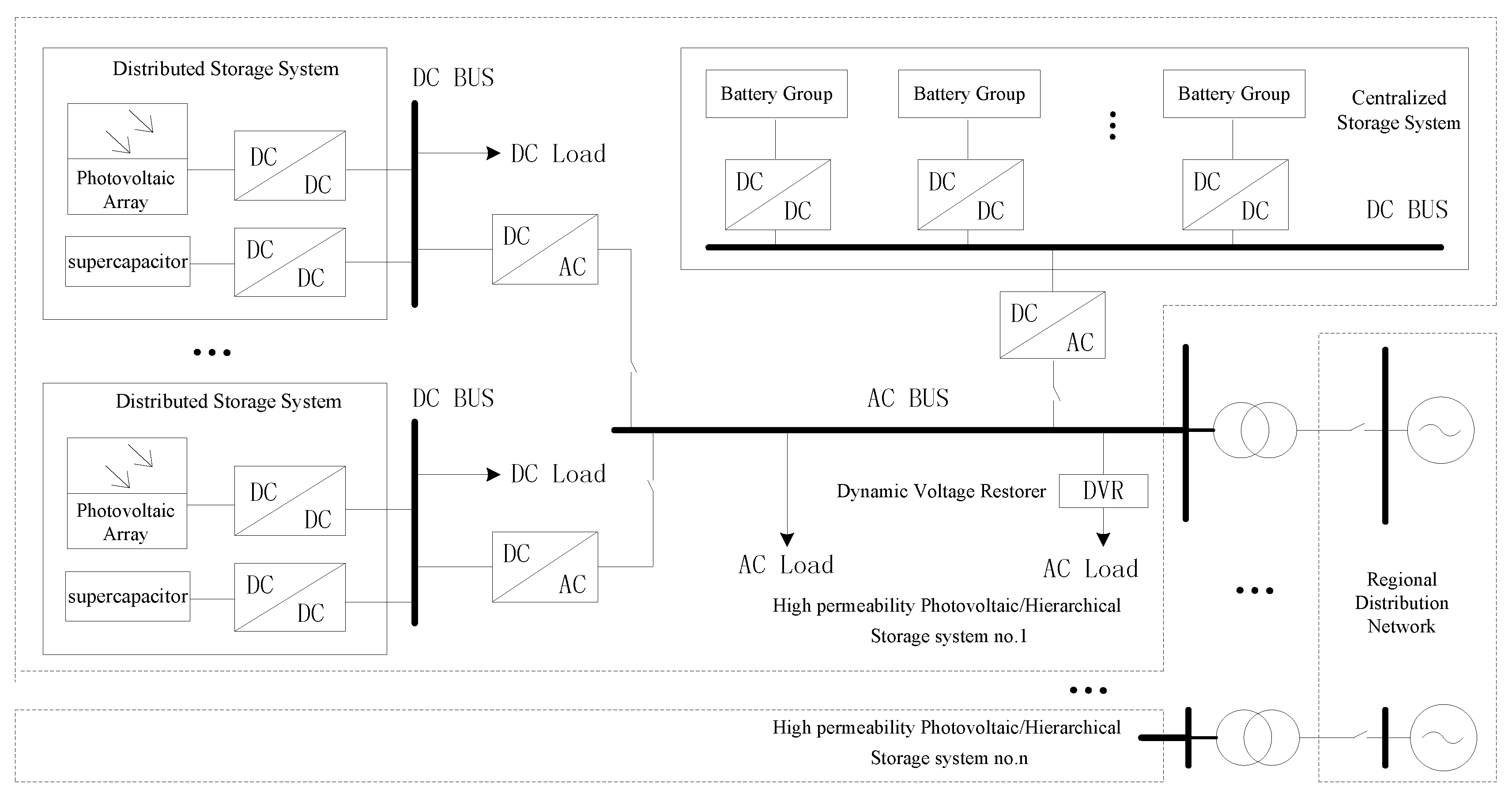
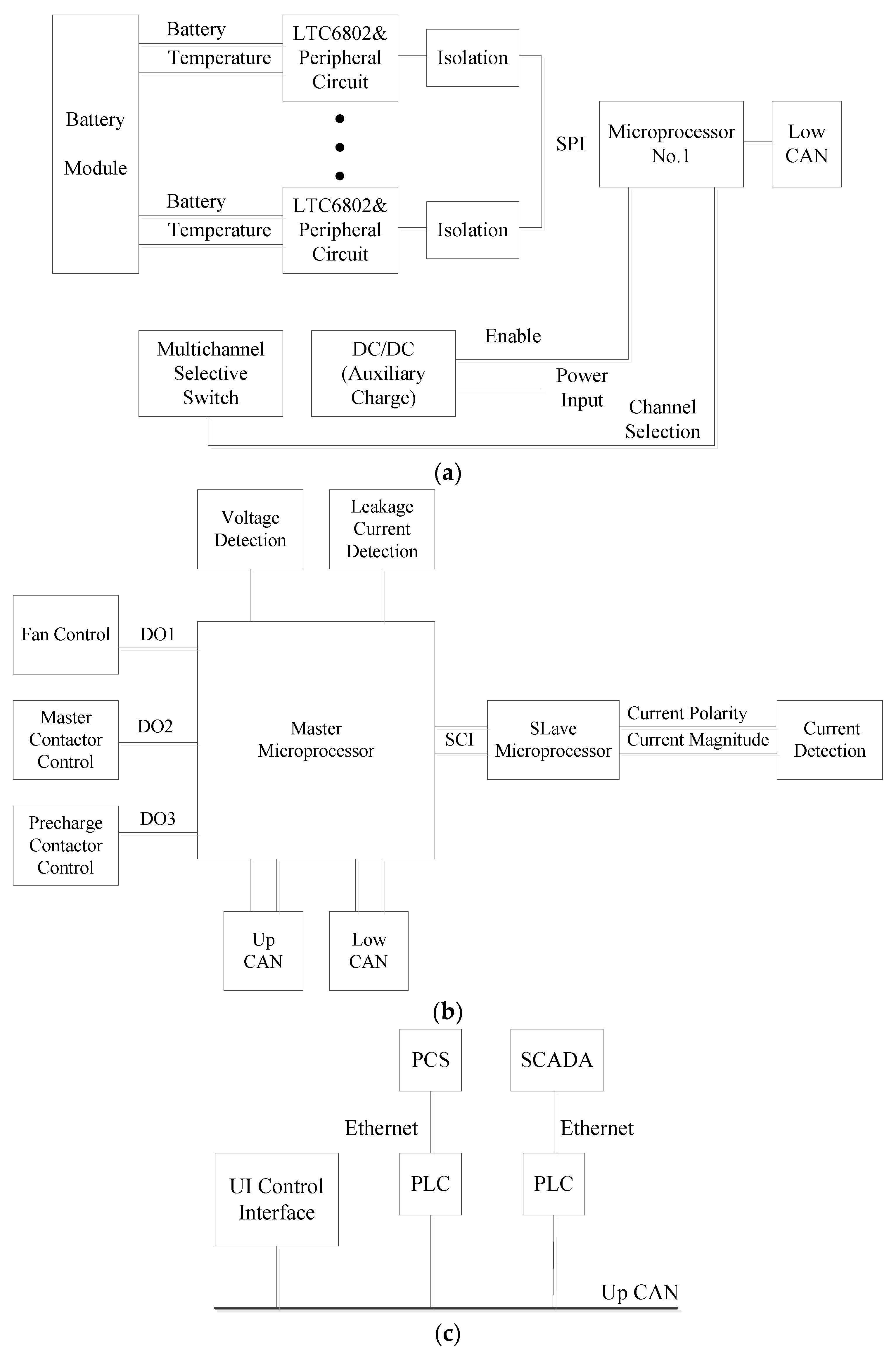
2.4. Hierarchical Structure

At present, many different kinds of energy storage devices are known, including batteries, supercapacitors, flywheels, superconducting magnetics and so on, most of which have different charge and discharge characteristics [15,16]. The bidirectional energy adjustment ability of energy storage devices make them play an important role in photovoltaic power systems. Compared with the single-technology energy storage system (ESS), a HESS can combine the advantages of each technology used, thus being more suitable for large-scale renewable energy systems. Typical combinations may include a battery and supercapacitor.
However, most storage devices are configured in the same place or just near photovoltaic power generators, so researchers are not very concerned about the configuration method of the battery and supercapacitor. This may lead to complex control circuits and inefficient control processes. A typical distribution network structure with hierarchical storage is shown in Figure 4.
In this typical structure, the centralized storage refers to a large-scale energy storage system consisting of mass energy storage devices connected in series or in parallel, that is generally configured in a particular area. The distributed storage refers to small-scale storage devices which are installed throughout the distribution network, and are generally configured in the same or nearby nodes of the photovoltaic system, in order to constitute a combined photovoltaic and storage power-generation system. Centralized storage is mainly used to implement overall coordinated control of distribution networks, while distributed storage takes charge of local power balancing of photovoltaics.
As the control targets of centralized storage and distributed storage are different, it’s necessary to select suitable storage devices to fit each target. Storage batteries have characteristics of low self-discharge, low manufacturing cost and high energy density, which makes them suitable for mass storage for a long time, so they are configured to constitute a centralized storage system (CSS). On the other hand, supercapacitors have high charge efficiency, high power density and rapid response speed. They are mainly used to adjust power oscillations of photovoltaics and they are configured to constitute a distributed storage system (DSS).
According to the configuration scheme, the high-frequency power oscillations are assigned to supercapacitors and the low-frequency oscillations are handled by storage batteries. Although the manufacturing cost of supercapacitors is higher than that of storage batteries, the smaller high-frequency power oscillations lead to smaller required supercapacitor capacity. This also conforms to the fact that supercapacitors are difficultly to scale at high power ratings due to cell voltage unbalancing issues.

3. Control Method

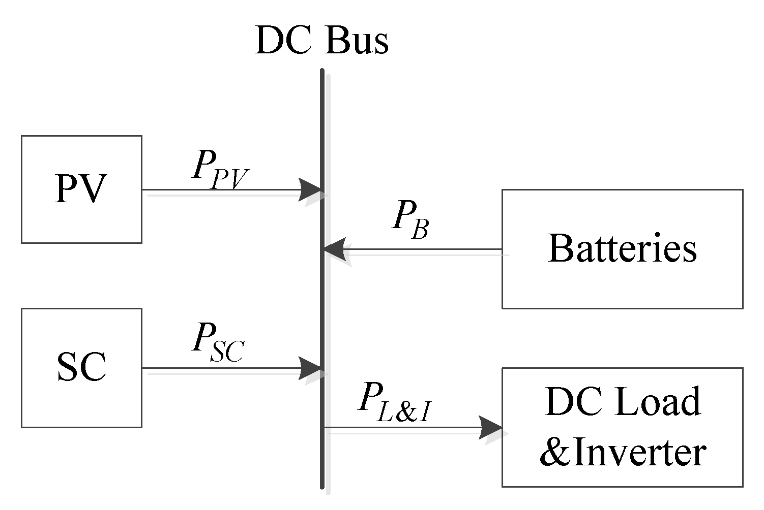
3.1. Control of a Single DC Bus Voltage

Firstly, we consider a single distributed storage system with storage batteries. The system structure is shown in Figure 5.
In the power allocation type control strategy, the voltage balance of the DC bus is controlled by both the photovoltaic and the energy storage system. The inverter power is given by the system as PI_ref. The output of the photovoltaic and load can be obtained by a prediction algorithm. Thus, the relational expressions of power are:
P L & I _ r e f = P L + P I _ r e f
P P V + P E S S _ r e f = P L & I _ r e f
P E S S _ r e f = P S C _ r e f + P B _ r e f
According to the allocation principle of high and low frequency power oscillations, we use a low pass filter (LPF) to obtain the reference power of the supercapacitor and battery. The control block diagram is shown in Figure 6.
The transfer function of LPF is G(s) = 1/1+Ts, so the reference power of supercapacitor and battery are:
P B _ r e f = 1 1 + T s × P E S S _ r e f
P S C _ r e f = P E S S _ r e f 1 1 + T s × P E S S _ r e f
where T is the time constant of LPF.
Now, we discuss the relationship between the time constant and the necessary capacity of the storage system. Usually, we can get the forecast power curve of the photovoltaic and load. Setting the time constant T, we can get PB_ref and PSC_ref from Equations (4)–(8). Then, we calculate the integral for PB_ref and PSC_ref according to the control time. Finally, considering the efficiency and capacity margin, we can obtain the needed storage system capacity.

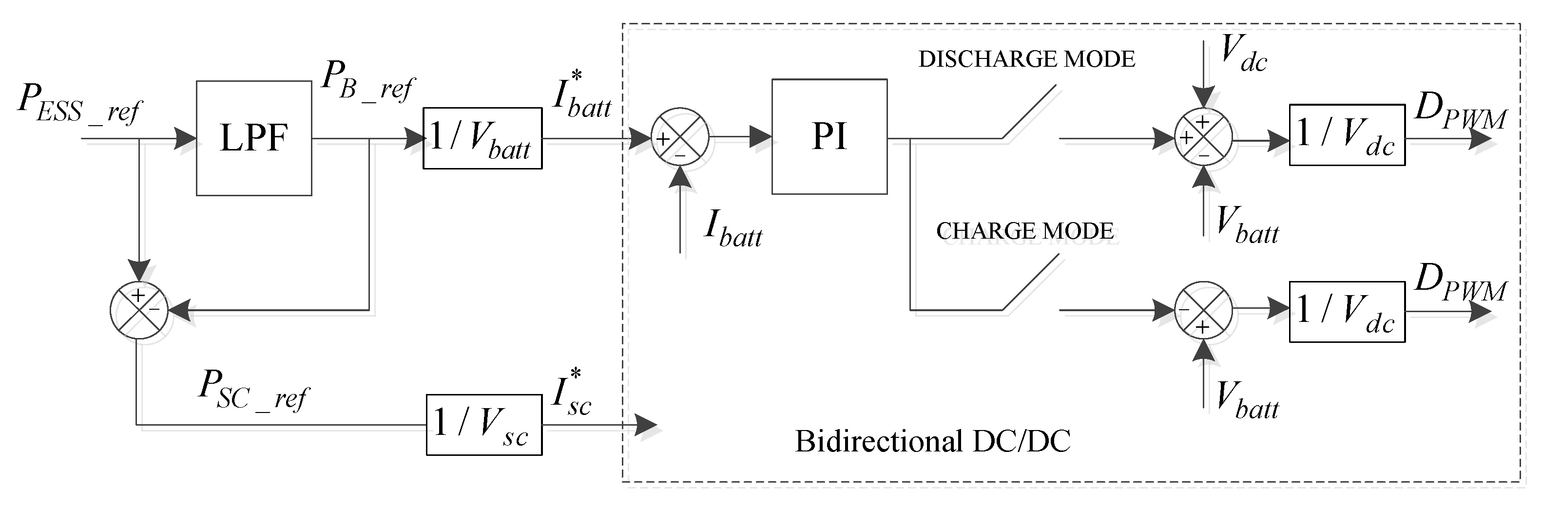
3.2. Control of System

Considering multiple distributed storage systems with a centralized storage system, the paper proposes an improved control structure upon construction of the distribution network shown in Figure 4. Taking three distributed storage systems as an example, the control structure is shown as Figure 7. Except for those installed in series with the photovoltaic array, all DC/DCs are bidirectional.
Focusing on DSS1, the outputs of photovoltaic, supercapacitor and battery adjust the voltage of DC bus1 together. Now PB1 is the required power of battery. According to the aforementioned control method, PB1 is:
P B 1 = 1 1 + T 1 s ( P L 1 P P V 1 )
Similarly, we have:
P B 2 = 1 1 + T 2 s ( P L 2 P P V 2 )
P B 3 = 1 1 + T 3 s ( P L 3 P P V 3 )
Defining P i n v as power vacancy from AC bus, we can obtain the energy control relationship as
P B 1 + P B 2 + P B 3 + P i n v = P C S S
Through the above analysis, we know that supercapacitors in the distributed storage system are only used to balance the high-frequency power oscillations of the DC bus. Batteries in a centralized storage system have two effects, one is to balance the low-frequency power oscillations of DC bus as PB1, PB2 and PB3, the other is to remain the power balance of AC bus as Pinv. This configuration structure can manage mass batteries in one place in a centralized way, which can reduce the control modules that need to be distributed in the distribution network. Moreover, different DC buses have different voltage grades, thus this is convenient for accessing various DC loads.

3.3. Constraint Condition

The above discussion doesn’t include photovoltaic and energy storage constraints, but actually the parameters of devices are important and the system restrictions need to be taken into account when formulating control strategies.
The system power balance constraint is:
i n P P V i + j l P E S j + P S P G = P L _ A C
where PPV is the photovoltaic output power, n is the total number of photovoltaics, PES is the output power of each energy storage. In this case, it’s only a battery. When it’s positive, energy storage is discharging, while when it’s negative, energy storage is charging. l is the total number of energy storage devices. PSPG is the tie-line power of other power grids. PL_AC is the AC load power.
The bus-bar voltage constraint is:
0.95 U e U B U S 1.05 U e
where Ue is the rated bus-bar voltage and UBUS is the actual bus-bar voltage.
Photovoltaic output constraint is:
P ¯ P V i min P P V i P ¯ P V i max
where P ¯ P V i min and P ¯ P V i max are the inferior and superior power limits for the photovoltaic, respectively.
Battery and supercapacitor power constraints are:
P B min P B P B max
P S C min P S C P S C max
where PB is the actual battery power, PSC is the actual supercapacitor power. PBmin and PBmax are the inferior and superior power limits of the batteries, respectively. PSCmin and PSCmax are the inferior and superior power limita of the supercapacitor, respectively.
The state of charge (SOC) of the battery is calculated as:
S O C B ( t ) = S O C B 0 1 λ C N 0 t η I d t
where SOCB is the actual SOC of the battery, SOCB0 is the initial battery SOC, CN is the rated capacity of the battery, λ is the influence factor of battery capacity, η is the battery efficiency.
The SOC of supercapacitor is related to its voltage, which can be expressed as:
S O C S C ( t ) = U S C 2 ( t ) U S C max 2
where SOCSC is the actual SOC of the supercapacitor, U S C ( t ) is the actual voltage of the supercapacitor, and U S C max is the maximum allowable voltage of the supercapacitor.
Thus, the battery and supercapacitor SOC constraints are:
S O C B min S O C B S O C B max
S O C S C min S O C S C S O C S C max
where S O C B min and S O C B max are the inferior and superior SOC limits for batteries, respectively, and S O C S C min and S O C S C max are the inferior and superior SOC limits for supercapacitors, respectively.

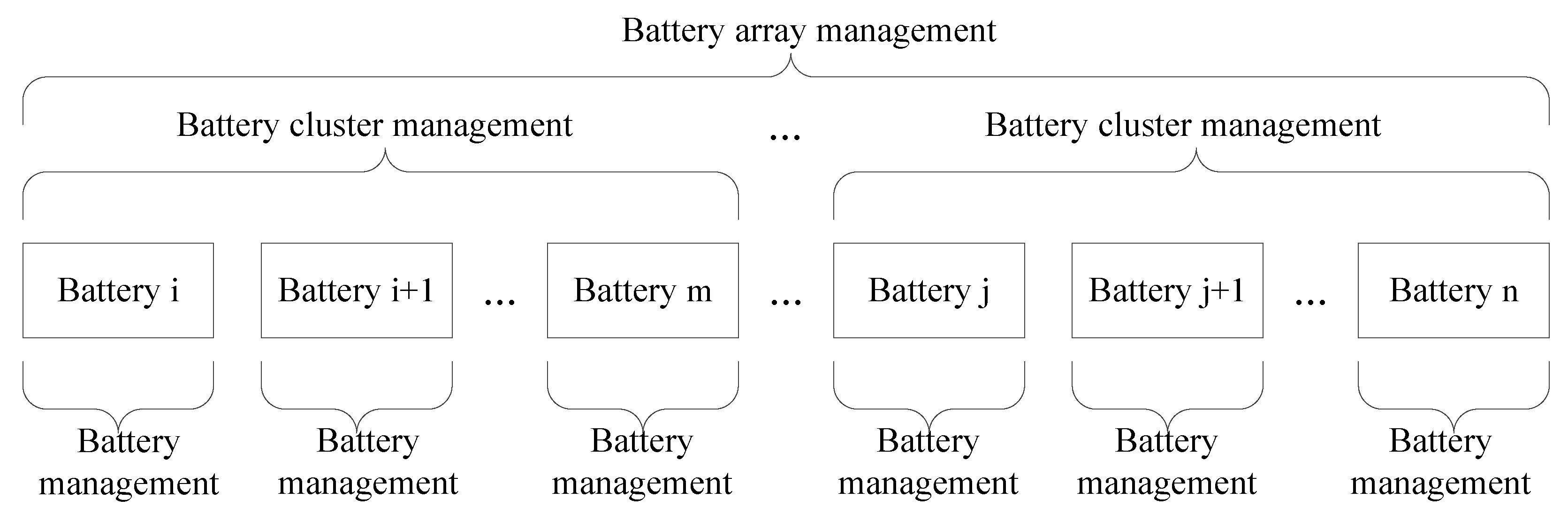
3.4. Centralized Management of Mass Batteries

Mass batteries connected in series or parallel bring problems of current and voltage sharing. After working for a long time, the SOC of each battery cannot stay the same. Coordination control of all batteries becomes complex and difficult. Thus a hierarchical management structure of batteries is proposed, which divides battery management into battery management, battery cluster management and battery array management, as shown in Figure 8.
Battery management in the bottom layer takes charge of single battery voltage sampling, multipoint temperature collection and battery equalization control. Battery cluster management in middle layer controls all the batteries of a battery cluster, taking charge of the total voltage acquisition of the battery string, charging and discharging current collection, electric leakage detection, failure warnings and SOC calculations. It realizes high-voltage management and completes the equilibrium control of the battery cluster. Battery array management in the top layer controls all battery clusters in the whole battery system. By collecting data and warning information from battery strings, it summarizes, counts, analyzes and deals with all the information of the battery system, in order to make batteries meet the requirements of centralized control [17]. The control circuits of each layer are shown in Figure 9.
The single battery management circuit includes a main control, battery monitoring, battery switching, communication interface and so on. An LTC6802 is an IC for battery monitoring which is used as the main management chip. The configuration purpose of the power input and auxiliary charge DC/DC is to balance the SOC of different batteries. Two microprocessors are applied in the battery cluster management circuit.
The master microprocessor is responsible for operational management of the control circuit, while the slave microprocessor takes charge of current collection and relevant calculations. Up CAN and Low CAN is respectively used to communicate with the battery array and single battery management circuits. Finally, the UI control interface and communication network are arranged in the battery array management. Through this control structure, we expect to realize coordinated control of batteries.

4. Simulation

The simulation platform is built by PSCAD to assess the performance of the energy management strategy. The simulation parameters are listed in Table 1.
We select a typical photovoltaic and energy-storage hybrid distribution network, and obtain the corresponding photovoltaic output prediction curve by some prediction technique such as a grey forecasting model or neural network [18]. To simplify the simulation process, we assume a constant DC load Pload = 49 kW.

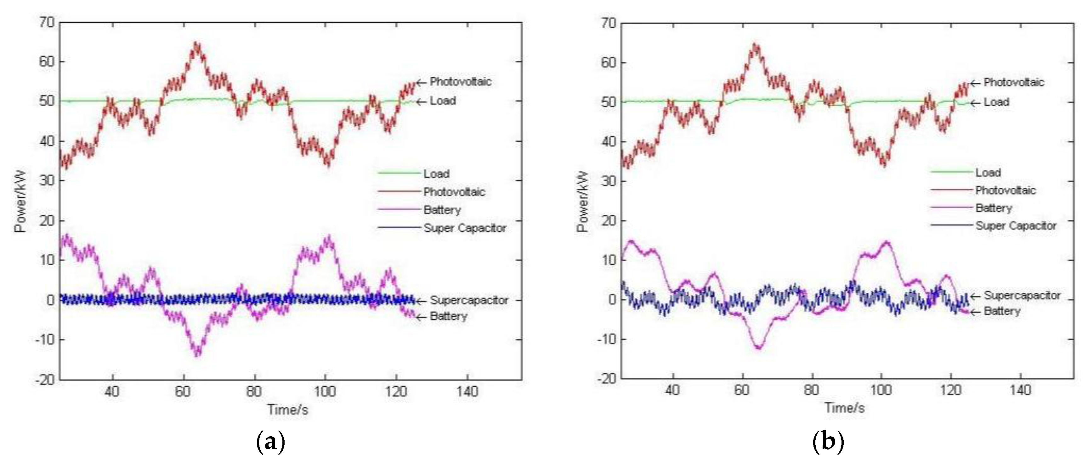
4.1. Single Control for a Short Time Scale

We take a single DC bus as an example to verify the regulating effect of battery and supercapacitor. The output waveforms for different time constants are shown in Figure 10. The numbers of batteries in series and parallel are 110 and 20, respectively, while the numbers of series and parallel supercapacitors are 150 and 2.
Figure 10a shows that when T = 0.1 s, the supercapacitor output has a fast fluctuation, but its fluctuation amplitude is small. Part of the high-frequency fluctuating power is adjusted by batteries. That makes the battery power output change frequently, which will reduce the battery’s service life. Figure 10d shows that when T = 10 s, the supercapacitor amplitude fluctuation is quite large, but the supercapacitor can hardly be scaled at a high power rating. What’s more, the battery outputs cannot track the photovoltaic fluctuations efficiently. Thus, a reasonable time constant can ensure a better control effect. Through the simulation waveform, we know that when 1 s < T < 5 s, the control effect is quite ideal.

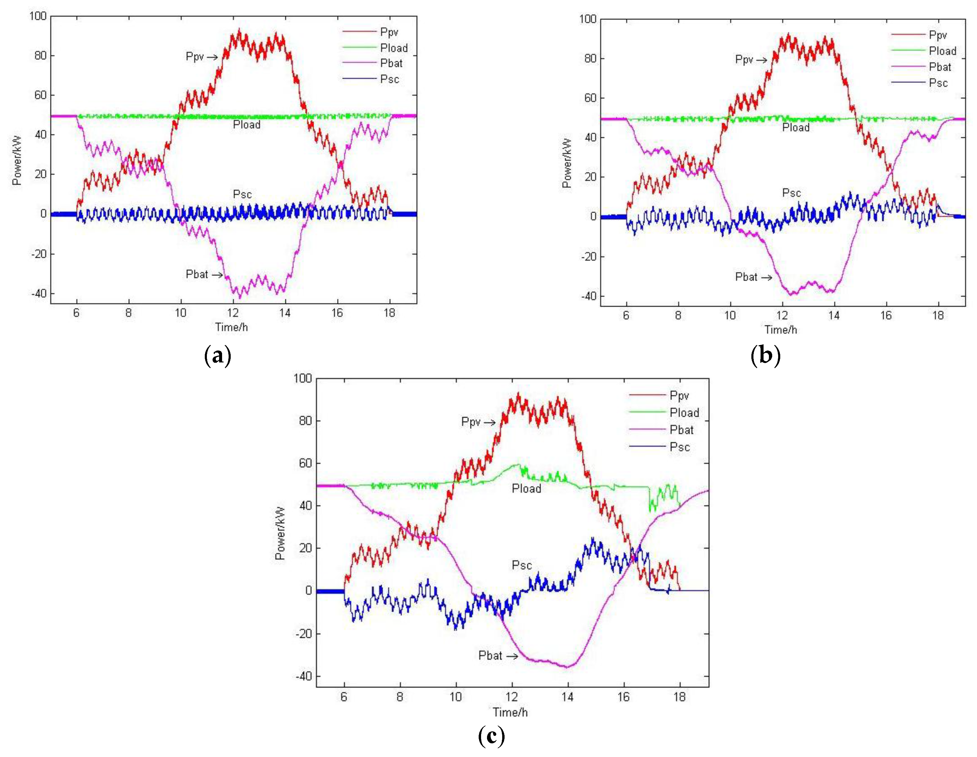
4.2. Single Control for a Long Time Scale

Considering single control for a long time scale, we select the daytime output of the photovoltaic system. Due to the extended control time, larger battery and supercapacitor capacities are required. Meanwhile, the time constant will be longer than in the former simulation. Now the numbers of batteries in series and parallel are 110 and 100, respectively, while the numbers of series and parallel supercapacitors are 150 and 80. The output waveforms for different time constants are shown in Figure 11.
When T = 150 s, the output waveform of the battery is unsmooth. Battery power changes acutely, which will lead to a shorter battery service life. When T = 2400 s, due to the capacity limitations, the supercapacitor voltage reaches the DC bus voltage after 12:00, which makes supercapacitor unable to charge. Thus Pload can’t stay stable. This shows that the needed capacity of the storage system must be taken into account when determining the time constant. When T = 600 s, the output waveform is better than the other cases.

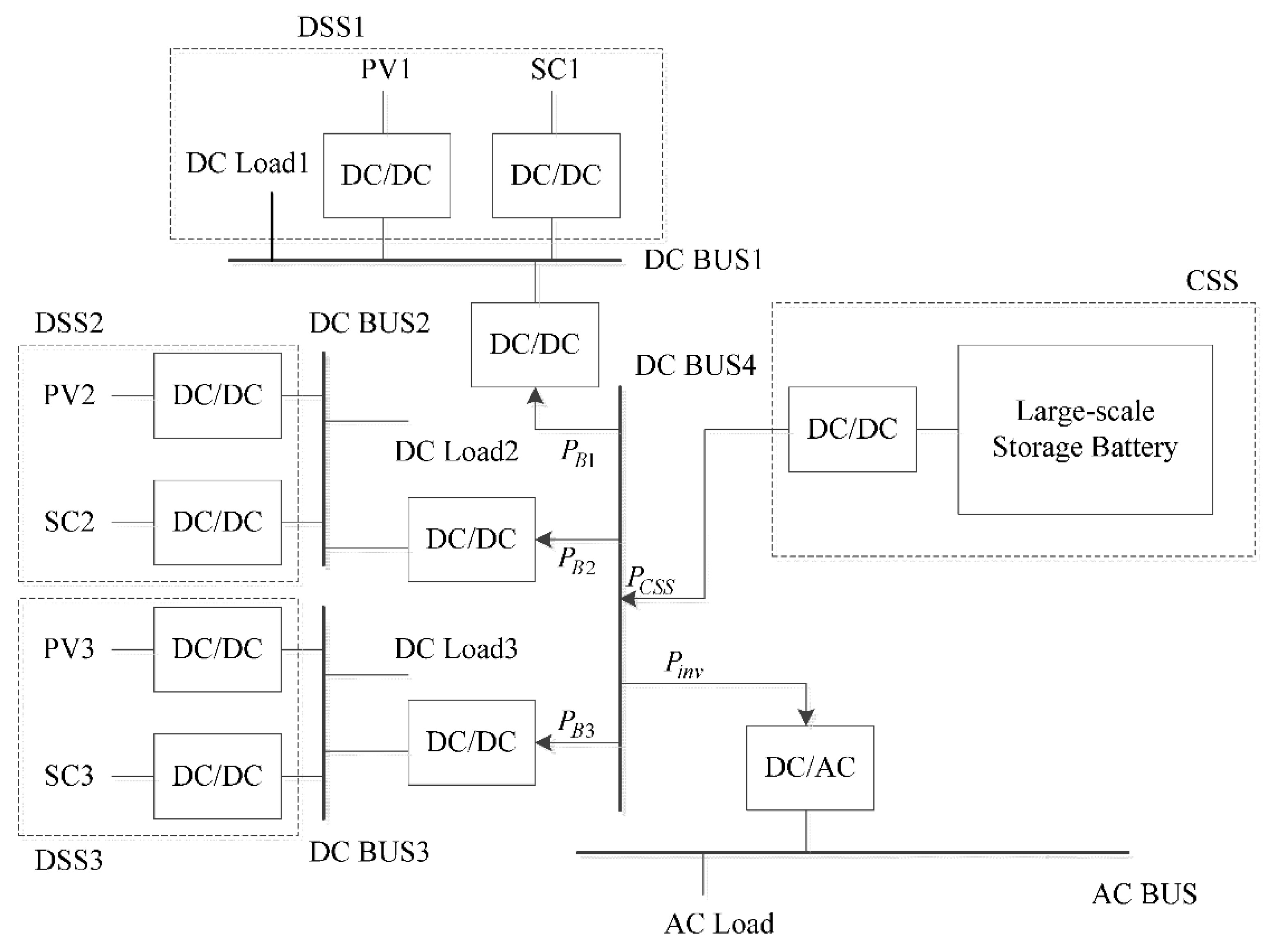
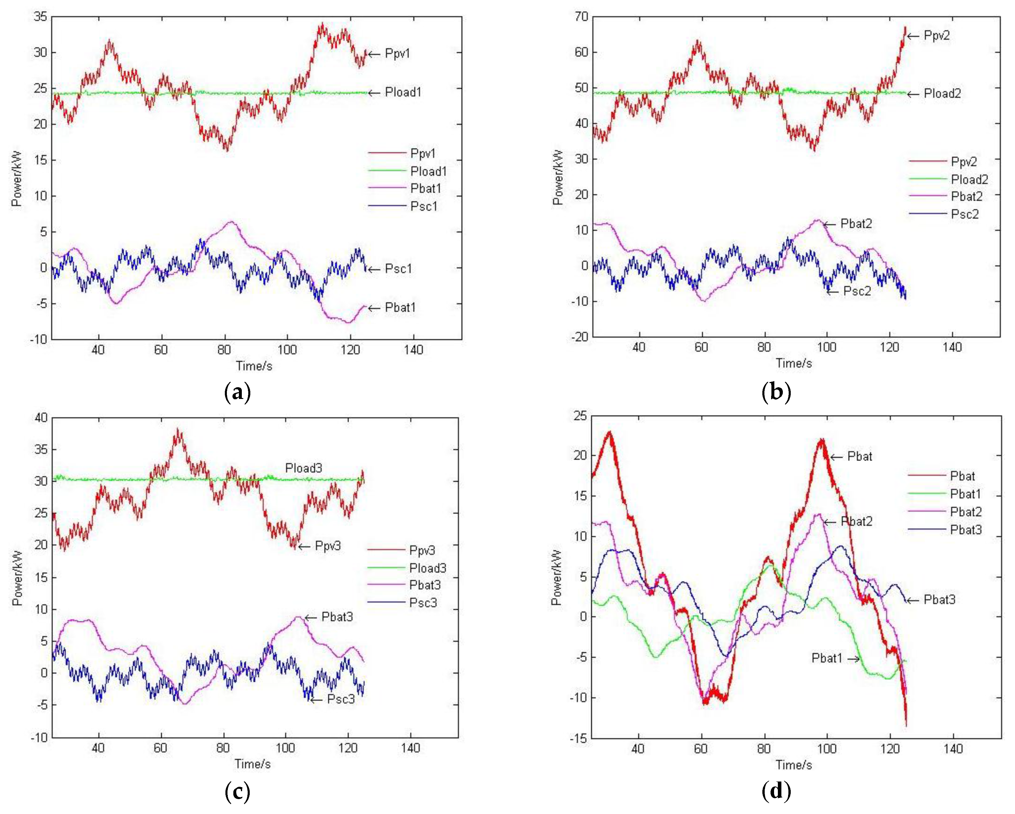
4.3. Control of Three Distributed Storage Systems

Now we carry out a simulation of the system shown in Figure 7. To simplify the simulation process, we assume that Pinv = 0, which means the hybrid system is operating under the island mode. Batteries use constant-voltage control. The simulation parameters are shown in Table 2.
Based on the previous discussion, we set the time constant T = 3 s. The output waveforms are shown in Figure 12.
The results show that supercapacitors in each distributed storage system can stabilize the high-frequency fluctuating power well. The low-frequency part can be assigned reasonably through the converging bus (DC Bus 4).

5. Conclusions and Prospects

Energy management of hybrid energy systems is significant against the background of wide application of photovoltaic generation. This paper models photovoltaics, storage batteries and supercapacitors, and then introduces a typical distribution network structure with hierarchical storage. A low pass filter is used to achieve regulation of high and low frequency photovoltaic fluctuations. The high-frequency power oscillations are assigned to supercapacitors and the low-frequency oscillations are handled by storage batteries. On this basis, the paper proposes an improved configuration structure which is convenient for accessing various DC loads and can centrally manage mass batteries in one place. Compared to traditional hybrid storage structures, this hierarchical structure can simplify the control circuit and control process, and improve control efficiency. To solve the problem caused by centralized management of mass batteries, the paper introduces a three-layer management structure. The control objects and control circuits are discussed.
The simulation results verify the control effect of battery and supercapacitor. When the time constant 1 s < T < 5 s, a better output waveform can be achieved. More experiments should be done however to verify the control effectiveness of multiple distributed storage systems. Power scheduling of centralized storage systems with AC buses should also be taken into consideration. The hierarchical control structure is expected to optimize the operation of photovoltaic and energy-storage hybrid systems.

Acknowledgments

This research is supported by the National Key Basic Research Program of China 973 Program (2015CB251301).

Author Contributions

Chang Ye and Shihong Miao conceived and designed the study. Chang Ye, Qi Lei and Yaowang Li carried out the simulation. Chang Ye, Shihong Miao and Qi Lei analyzed simulation results. Chang Ye, Qi Lei and Yaowang Li wrote the paper. Chang Ye, Shihong Miao and Yaowang Li reviewed and edited the manuscript. All authors read and approved the manuscript.

Conflicts of Interest

The authors declare no conflict of interest.

Nomenclature

I p h current of photo-generated current source
R s h internal parallel resistance of silicon solar cells
R s internal series resistance of silicon solar cells
I P V output current of photovoltaic
V P V output voltage of photovoltaic
I s diode saturation current
q a constant ( 1.602 × 10 19 C )
k Boltzmann constant ( 1.381 × 10 23 J / K )
T P V absolute temperature when photovoltaic works
A diode feature fitting coefficient
S the actual irradiance
S r e f irradiance at standard condition
T r e f absolute temperature when photovoltaic works at standard condition
C T temperature coefficient
I p h , r e f photo-generated current at standard condition
Eno-load voltage
E 0 battery constant voltage
Kpolarisation voltage
Qbattery capacity
i d t actual battery charge
Aexponential zone amplitude
Bexponential zone time constant inverse
V b a t t battery voltage
I b a t t battery current
P I _ r e f reference value of inverter power
P L _ A C AC load power
P L & I _ r e f power of load and inverter
P E S S _ r e f reference power of storage system
P P V actual power of photovoltaic
P S C _ r e f reference power of supercapacitor
P B _ r e f reference power of battery
V s c supercapacitor voltage
I b a t t * reference value of battery current
I s c * reference value of supercapacitor current
V d c DC bus voltage
D P W M duty ratio of PWM control
T time constant of low pass filter
n the total number of photovoltaic
P E S output power of each energy storage
l total number of energy storages
P S P G tie-line power of other power grids
U e rated voltage of bus-bar
U b u s actual voltage of bus-bar
P ¯ P V i min , P ¯ P V i max inferior and superior limit of power for photovoltaic
P B min , P B max inferior and superior limit of power for batteries
P S C min , P S C max inferior and superior limit of power for supercapacitor
S O C B 0 initial SOC of battery
C N rated capacity of battery
λ influence factor of battery capacity
η battery efficiency
S O C B actual SOC of battery
S O C S C actual SOC of supercapacitor
U S C ( t ) actual voltage of supercapacitor
U S C max max allowable voltage of supercapacitor
S O C B min , S O C B max inferior and superior limit of SOC for batteries
S O C S C min , S O C S C max inferior and superior limit of SOC for supercapacitor
P l o a d power of DC load
P l o a d 1 , P l o a d 2 , P l o a d 3 power of DC load 1, 2, 3

References

  1. Yang, W.; Xia, Z.; Feng, X. Impacts of large scale and high voltage level photovoltaic penetration on the security and stability of power system. In Proceedings of the Asia-Pacific Power and Energy Engineering Conference (APPEEC), Chengdu, China, 28–31 March 2010; pp. 1–5.
  2. Srivastava, A.K.; Kumar, A.A.; Schulz, N.N. Impact of distributed generations with energy storage devices on the electric grid. IEEE Syst. J. 2012, 6, 110–116. [Google Scholar] [CrossRef]
  3. Hill, C.A.; Such, C.S.; Chen, D. Battery energy storage for enabling integration of distributed solar power generation. IEEE Trans. Smart Grid 2012, 3, 850–857. [Google Scholar] [CrossRef]
  4. Kim, S.-T.; Bae, S.H. Energy management based on the photovoltaic HPCS with an energy storage device. IEEE Trans. Ind. Electron 2015, 62, 4608–4617. [Google Scholar] [CrossRef]
  5. Ge, B.; Abu-Rub, H. An Energy-stored quasi-z-source inverter for application to photovoltaic power system. IEEE Trans. Ind. Electron 2013, 60, 4468–4480. [Google Scholar] [CrossRef]
  6. Reddy, S.S.; Momoh, J.A. Realistic and transparent optimum scheduling strategy for hybrid power system. IEEE Trans. Smart Grid 2015, 6, 3114–3124. [Google Scholar] [CrossRef]
  7. Sun, K.; Xing, Y.; Guerrero, J.M. A distributed control strategy based on DC bus signaling for modular photovoltaic generation systems with battery energy storage. IEEE Trans. Power Electron 2011, 26, 3032–3045. [Google Scholar] [CrossRef]
  8. Liu, X.; Aichhorn, A. Coordinated Control of distributed energy storage system with tap changer transformers for voltage rise mitigation under high photovoltaic penetration. IEEE Trans. Smart Grid 2012, 3, 897–906. [Google Scholar] [CrossRef]
  9. Kabir, M.N.; Mishra, Y.; Ledwich, G. Coordinated control of grid-connected photovoltaic reactive power and battery energy storage systems to improve the voltage profile of a residential distribution feeder. IEEE Trans. Ind. Inform. 2014, 10, 967–977. [Google Scholar] [CrossRef]
  10. Lampropoulos, L.; Garoufalis, P.; Paul, P.J. Hierarchical predictive control scheme for distributed energy storage integrated with residential demand and photovoltaic generation. IET Gener. Transm. Distrib. 2014, 9, 2319–2327. [Google Scholar] [CrossRef]
  11. Tummuru, N.R.; Mishra, M.K.; Srinivas, S. Dynamic energy management of hybrid energy storage system with high-gain PV converter. IEEE Trans. Energy Convers. 2015, 30, 150–160. [Google Scholar] [CrossRef]
  12. Feng, X.; Gooi, H.B.; Chen, S.X. Hybrid energy storage with multimode fuzzy power allocator for PV systems. IEEE Trans. Sustain. Energy 2014, 5, 389–397. [Google Scholar] [CrossRef]
  13. Wang, G.; Ciobotaru, M.; Agelidis, G.A. Power smoothing of large solar PV plant using hybrid energy storage. IEEE Trans. Sustain. Energy 2014, 5, 834–842. [Google Scholar] [CrossRef]
  14. Zubieta, L.; Bonert, R. Characterization of double-layer capacitors (DLCs) for power electronics applications. IEEE Trans. Ind. Appl. 2000, 36, 199–205. [Google Scholar] [CrossRef]
  15. Komori, M.; Uchimura, Y. Improving the dynamics of two types of flywheel energy storage systems with SMBs. IEEE Trans. Appl. Supercond. 2005, 15, 2261–2264. [Google Scholar] [CrossRef]
  16. Lifshitz, D.; Weiss, G. Optimal control of a capacitor-type energy storage system. IEEE Trans. Autom. Control 2015, 60, 216–220. [Google Scholar] [CrossRef]
  17. Pei, L.; Huang, Z.; Dong, D. A hierarchical management system for energy storage batteries. Energy Storage Sci. Technol. 2014, 3, 416–422. [Google Scholar]
  18. Wang, S.; Zhang, N. Photovoltaic system power forecasting based on combined grey model and BP Neural network. In Proceedings of the International Conference on Electrical and Control Engineering (ICECE), Yichang, China, 16–18 September 2011; pp. 4623–4626.
Figure 1. Equivalent circuit of a solar cell.
Energies 09 00395 g001
Figure 2. Non-linear battery model.
Energies 09 00395 g002
Figure 3. Equivalent model circuit for the supercapacitor.
Energies 09 00395 g003
Figure 4. Construction of a distribution network with high permeability photovoltaic/hierarchical storage.
Energies 09 00395 g004
Figure 5. System structure of a single distributed storage system with storage batteries.
Energies 09 00395 g005
Figure 6. Control block diagram of a single distributed storage system with storage batteries.
Energies 09 00395 g006
Figure 7. Control structure of a multiple distributed storage system with centralized storage system.
Energies 09 00395 g007
Figure 8. Hierarchical management structure of batteries.
Energies 09 00395 g008
Figure 9. Battery management control circuits: (a) Single battery management and (b) Battery cluster management and (c) Battery array management.
Energies 09 00395 g009
Figure 10. Output waveforms for different time constants for short time scale. (a) T = 0.1 s; (b) T = 1 s; (c) T = 5 s; (d) T = 10 s.
Energies 09 00395 g010aEnergies 09 00395 g010b
Figure 11. Output waveforms for different time constants for long time scale. (a) T = 150 s; (b) T = 600 s; (c) T = 2400 s.
Energies 09 00395 g011
Figure 12. (a) Distributed storage system 1; (b) Distributed storage system 2; (c) Distributed storage system 3; (d) Waveforms of battery power.
Energies 09 00395 g012
Table 1. Battery and supercapacitor simulation parameters.
Storage BatterySupercapacitor
Rated Voltage3.6 V C i 0 270 F
Maximum Voltage4.2 V C i 1 × V c i 190 F/V
Capacity1 Ah C d 100 F
Control Parameters C l 220 F
Storage BatteryP = 35, I = 1.2 × 10⁵ R i 2.5 mΩ
SupercapacitorP = 45, I = 1.2 × 10⁵ R d 0.9 Ω
DC Bus Voltage700 V R l 5.2 Ω
Table 2. Simulation parameters of DC Bus voltage and DC load power.
DC Bus VoltageLoad Power
DC Bus 1220 V P l o a d 1 24.2 kW
DC Bus 2220 V P l o a d 2 48.4 kW
DC Bus 3220 V P l o a d 3 30.25 kW
DC Bus 4700 V/
Supercapacitor
Series Number50Parallel Number2

