Article

Experimental Study of Natural Convection Cooling of Vertical Cylinders with Inclined Plate Fins

Department of Mechanical Engineering, Ajou University, Suwon 443-749, Korea
*
Author to whom correspondence should be addressed.
Energies 2016, 9(6), 391; https://doi.org/10.3390/en9060391
Submission received: 12 April 2016 / Revised: 13 May 2016 / Accepted: 17 May 2016 / Published: 24 May 2016
(This article belongs to the Special Issue Advanced Heating and Cooling Techniques)

Abstract

:
In this paper, natural convection from vertical cylinders with inclined plate fins is investigated experimentally for use in cooling electronic equipment. Extensive experimental investigations are performed for various inclination angles, fin numbers, and base temperatures. From the experimental data, a correlation for estimating the Nusselt number is proposed. The correlation is applicable when the Rayleigh number, inclination angle, and fin number are in the ranges 100,000–600,000, 30°–90°, and 9–36, respectively. Using the correlation, a contour map depicting the thermal resistance as a function of the fin number and fin thickness is presented. Finally, the optimal thermal resistances of cylinders with inclined plate fins and conventional radial plate fins are compared. It is found that that the optimal thermal resistance of the cylinder with inclined fins is 30% lower than that of the cylinder with radial plate fins.

1. Introduction

Heat dissipation from electronic devices increases considerably with continuous needs for high performance, cost effective, and miniaturized electronic devices [1,2,3]. The high power dissipation from the electronic device raises the junction temperature of the device, which adversely influences the overall performance and durability of the device. One example is a light-emitting diode (LED), the efficiency of which is significantly reduced as the junction temperature increases due to an increase in the nonradiative recombinations through defect states and an increase in the leakage of carriers from the quantum well [4,5]. Therefore, thermal management of electronic devices is important to maintain their performance and durability [6,7]. Various cooling techniques for thermal management have been suggested; among these, natural convective heat sinks have proven to be appropriate because of their outstanding simplicity, reliability, and low cost [8].
Many studies have focused on natural convective heat sinks, as reviewed in Martynenko and Khramtsov [9] and in Raithby and Hollands [10]. In particular, many previous researchers investigated natural convection from cylindrical heat sinks, which are cylindrical bodies with fins attached. These studies are motivated by the fact that the heat dissipation from the cylinder can be increased by using the fins. Sparrow and Bahrami investigated heat transfer from square vertical fins attached to a horizontal tube by using the naphthalene sublimation technique [11]. Chen and Chou also conducted an experimental study of horizontal cylinders with square vertical fins [12]. Yildiz and Yüncü suggested a Nusselt number correlation for annular fin arrays mounted on a horizontal cylinder from their experimental data [13]. Hahne and Zhu also suggested a Nusselt number correlation for horizontal cylinders with annular fins from measured heat transfer coefficients [14]. Recently, vertical cylinders with vertically oriented radial plate fins, as shown in Figure 1, are widely used for cooling LED lighting. For natural convection from these cylinders with radial plate fins, an empirical correlation for estimating the Nusselt number was proposed by our group [15].
Heat transfer through inclined fins is currently of considerable interest. Takeishi et al. investigated convective heat transfer in rectangular ducts with inclined pin fins. They showed that ducts with inclined pin fins have higher thermal performance compared to those with normal pin fins because of the low pressure loss and the extended area of inclined pin fin surfaces [16]. Hagote and Dahake investigated heat transfer from vertical plates with inclined plate fins under natural convection. They demonstrated that the average heat transfer coefficient is maximized when the inclination angle is 60° [17]. From these studies, we can expect that the thermal performance of vertical cylinders with radial plate fins (Figure 1) will be further enhanced by employing inclined plate fins as shown in Figure 2. It is mainly because the fin surface area of the vertical cylinder with inclined fins is greater compared to that with radial plate fins when the space reserved for the heat sink is fixed, i.e., the heat sink length L and the height H are fixed. However, to the best of our knowledge, the natural convection from vertical cylinders with inclined plate fins has not been experimentally investigated yet. As a result, there is no reliable experimental data by which one can obtain the Nusselt numbers, and there is no way to obtain the thermal resistance of vertical cylinders with inclined plate fins quantitatively. Therefore, the degree of improvement in the performance of cylinders with inclined plate fins compared to that of cylinders with conventional radial plate fins, and the conditions under which this improvement is achieved, are not clear.
The purpose of this study is to investigate natural convection cooling of vertical cylinders with inclined plate fins. Extensive experiments for various inclination angles, fin numbers, and base temperatures were conducted. From these results, a Nusselt number correlation is suggested. Using the correlation, a contour map depicting the thermal resistance as a function of the fin number and fin thickness is presented. Finally, the thermal resistances of cylinders with inclined plate fins and conventional radial plate fins are compared.

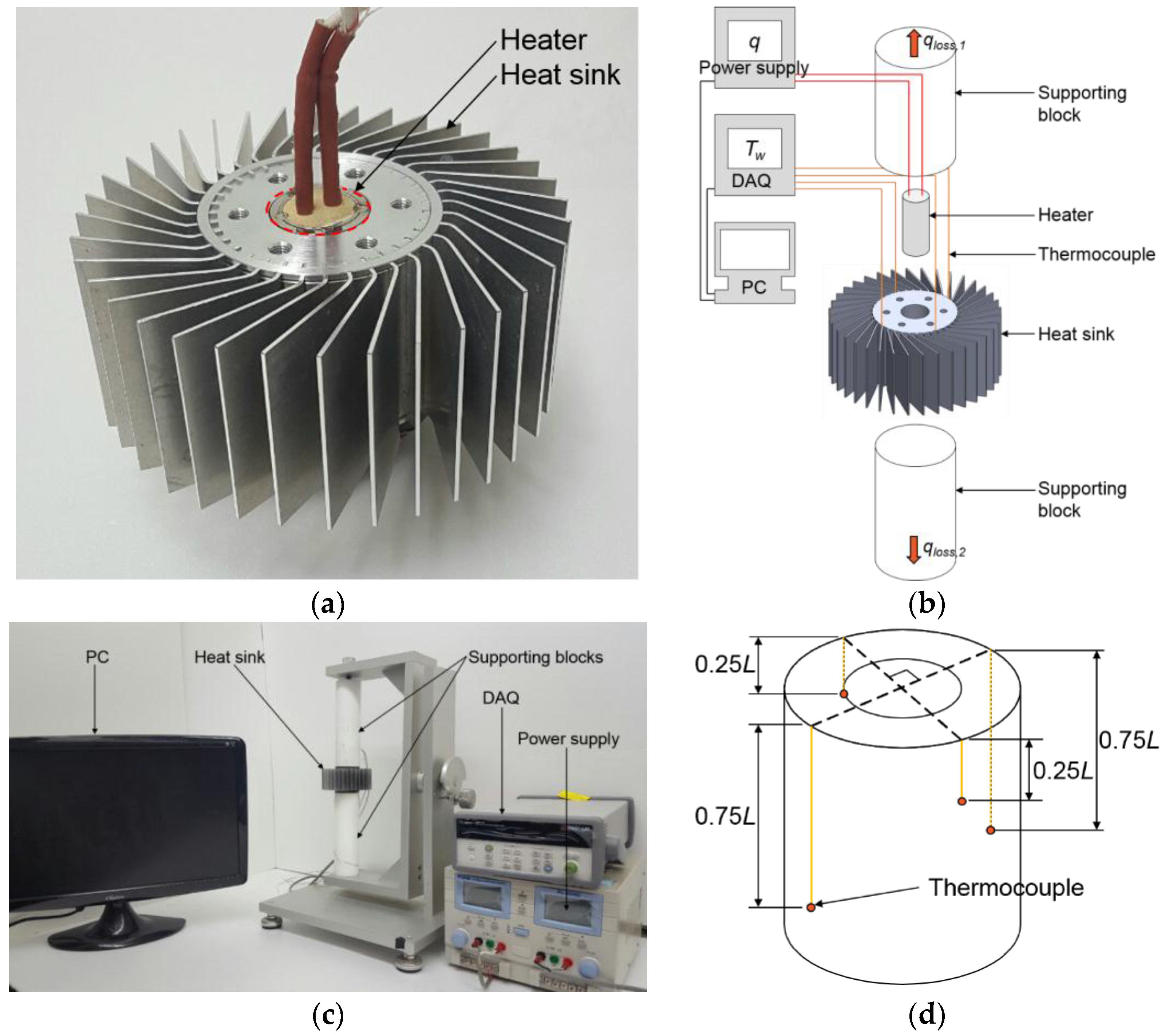
2. Experimental Investigation

The thermal resistances of natural convective heat sinks with inclined plate fins were measured for various inclination angles, fin numbers, and base temperatures. Schematic diagrams of the heat sinks are presented in Figure 2a, and the dimensions of the heat sinks are listed in Table 1. Eleven different heat sinks were used to cover a wide range of inclination angles and fin numbers. In Table 1, the heat sink with large fin number (N = 36) and large inclination angle (α = 90°) was excluded because the adjacent fins touch and bend each other in this heat sink because the space required for a single fin was insufficient for this case. An annular cylinder base and inclined fins for the heat sinks were made of aluminum alloys 6061 (k = 167 W/mK) and 5052 (k = 138 W/mK), respectively.
The heat sinks were assembled by interference fitting of the fins and base. Then, a cartridge heater was inserted into the inner hole of the base (Figure 3a). A thermal interface material (TC 5080; Dow Corning: Auburn, MI, USA) was used to minimize the contact thermal resistance between the heat sink base and the heater. The supporting cylindrical blocks, the length of which was 200 mm, were made of Teflon to minimize the heat loss from the top and bottom sides of the base (Figure 3b,c). Power was supplied to the heater from a power supply (E3633A; Agilent Technologies: Santa Clara, CA, USA) in the range 2–45 W. To calculate the actual heat transfer rate to the heat sink, the heat loss through the supporting blocks (qloss,1 + qloss,2 in Figure 3b) was measured and subtracted from the electric power supplied to the heater (Appendix A). To measure the base temperature, four T-type thermocouples were circumferentially attached to the cylinder (Figure 3d) A data acquisition unit (34970A DAQ; Agilent Technology) was used to acquire the signals from the thermocouples and convert them into temperature data. The temperatures were measured until the change in the temperature was smaller than ±0.1 °C in a 2 min period. The experiments were performed in an isolated and quiescent room.

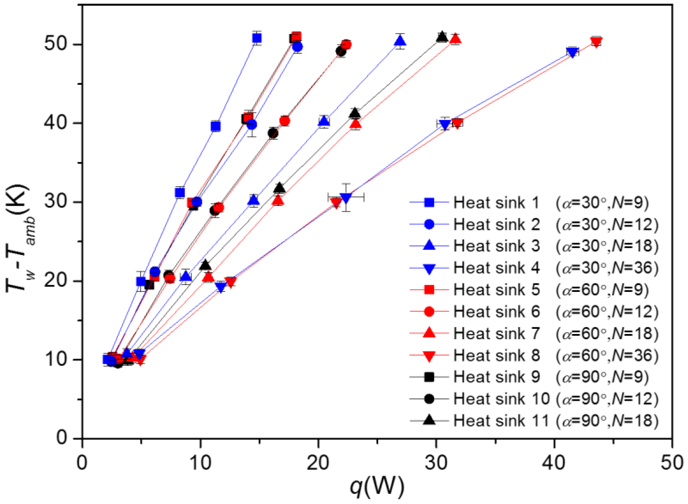
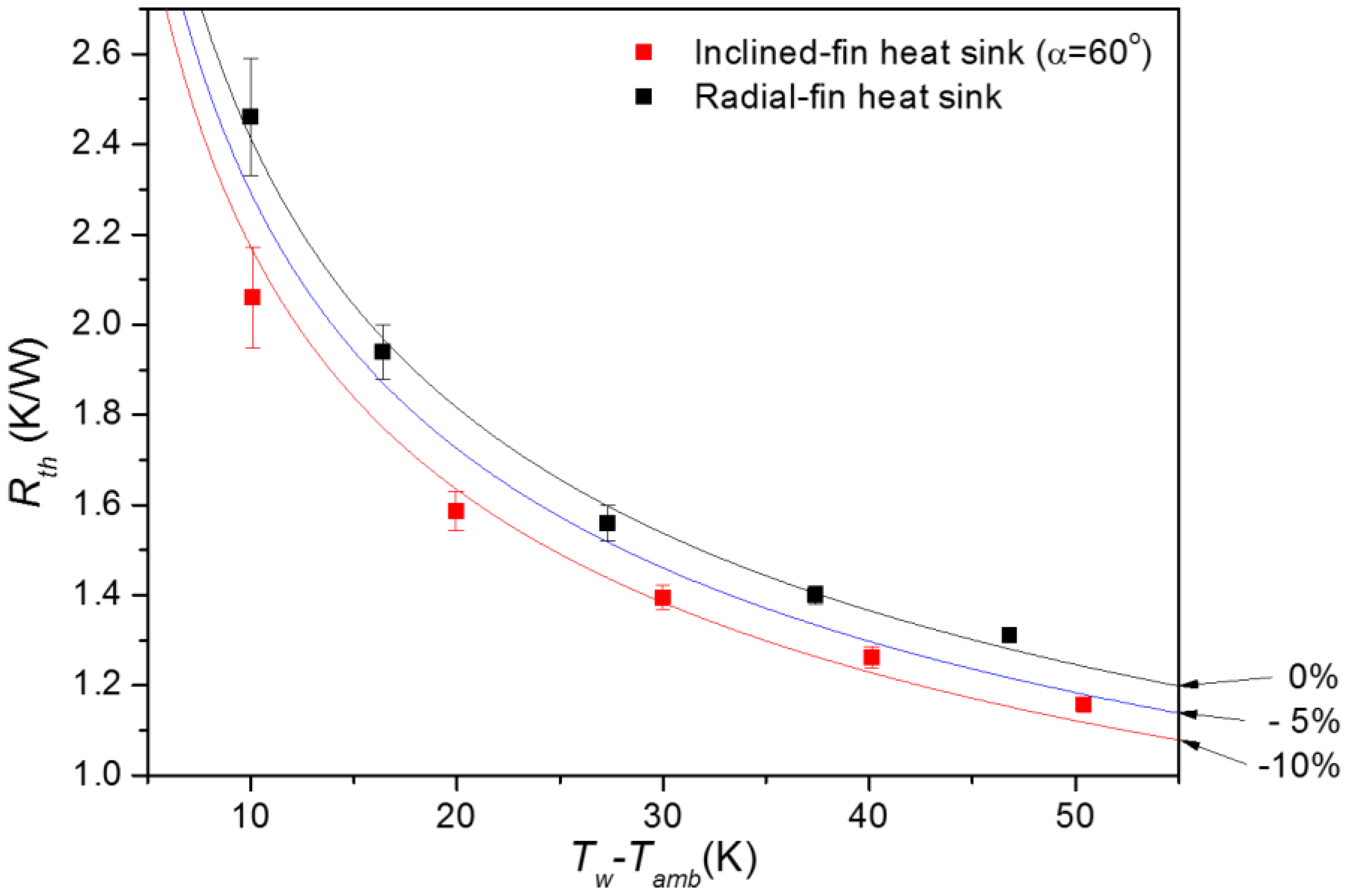
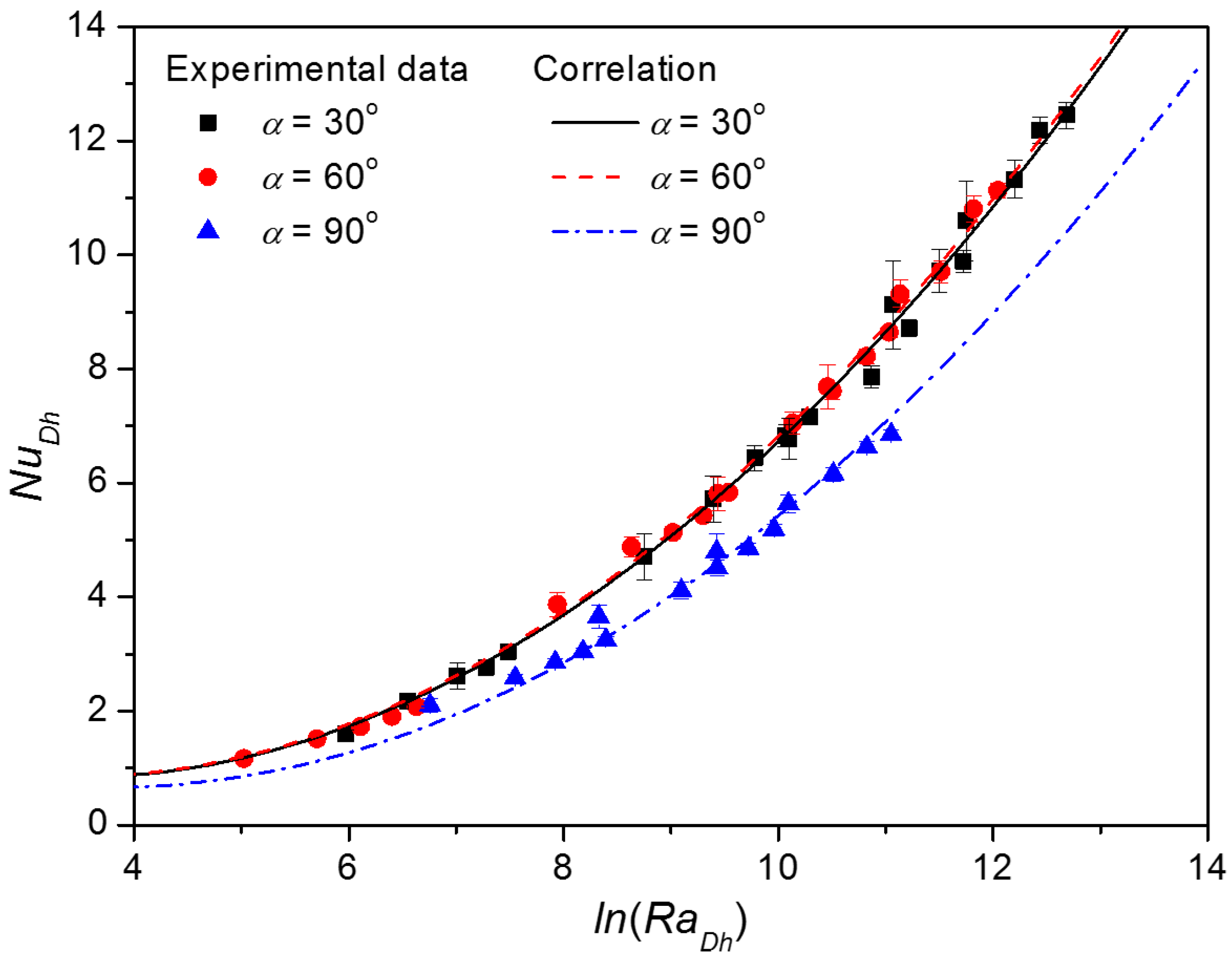
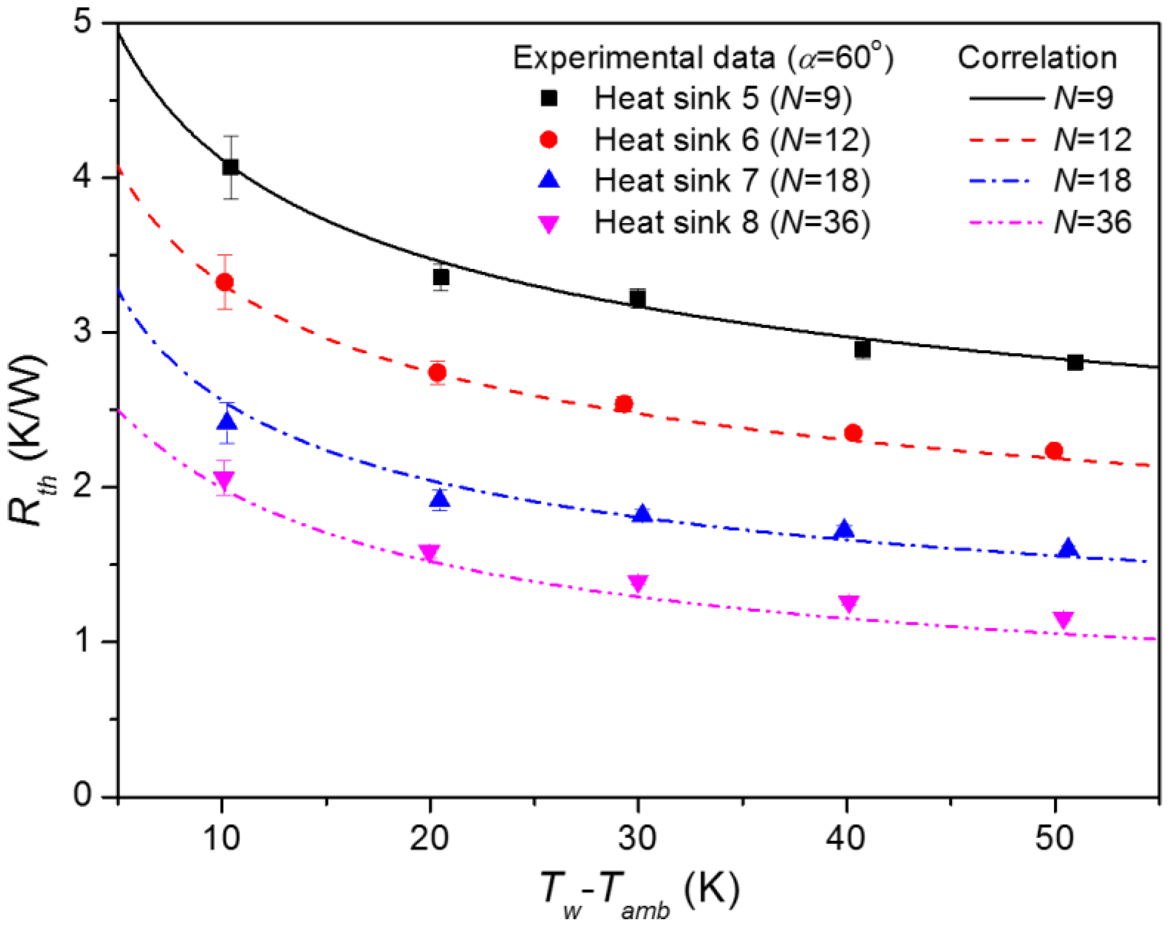
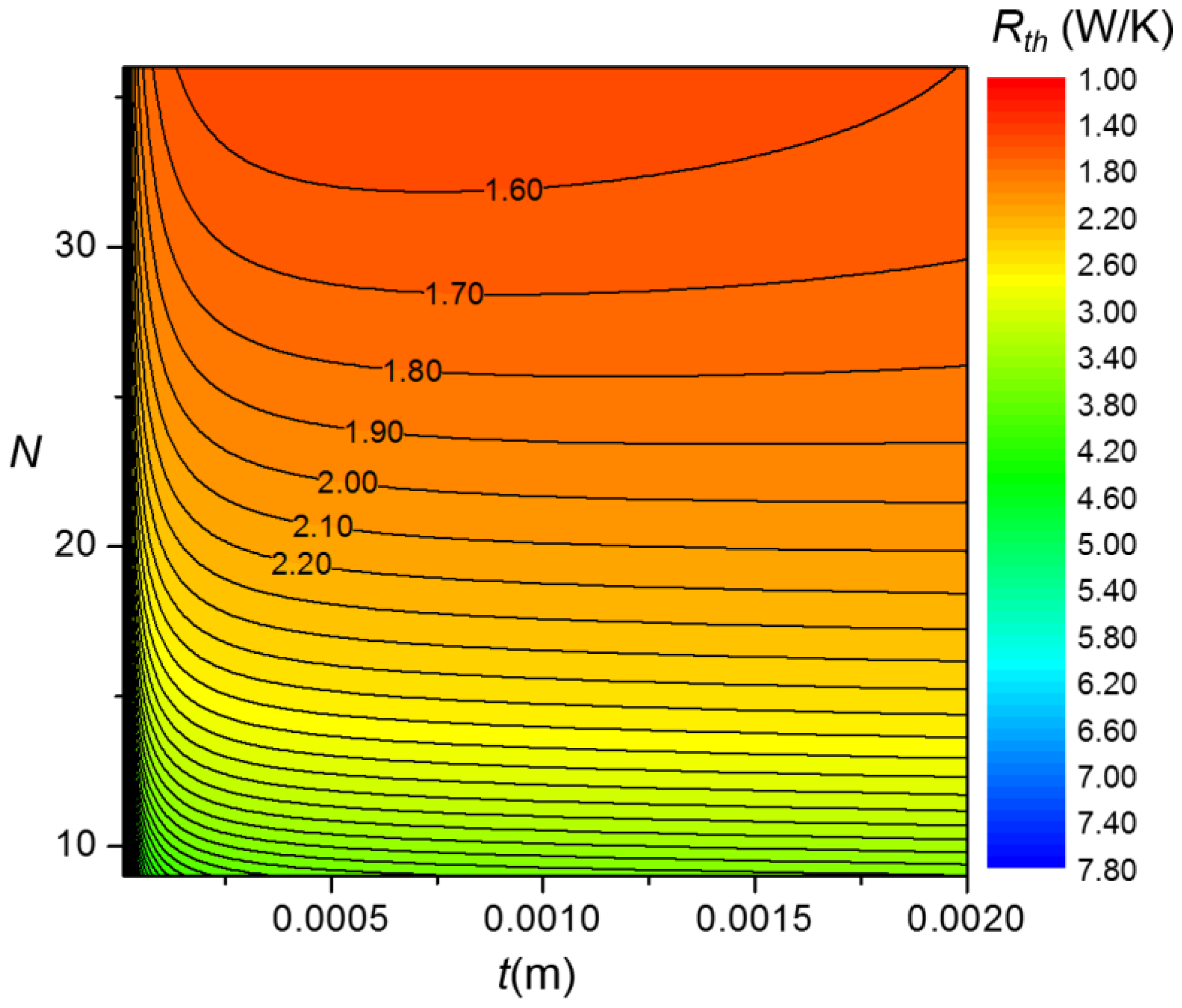
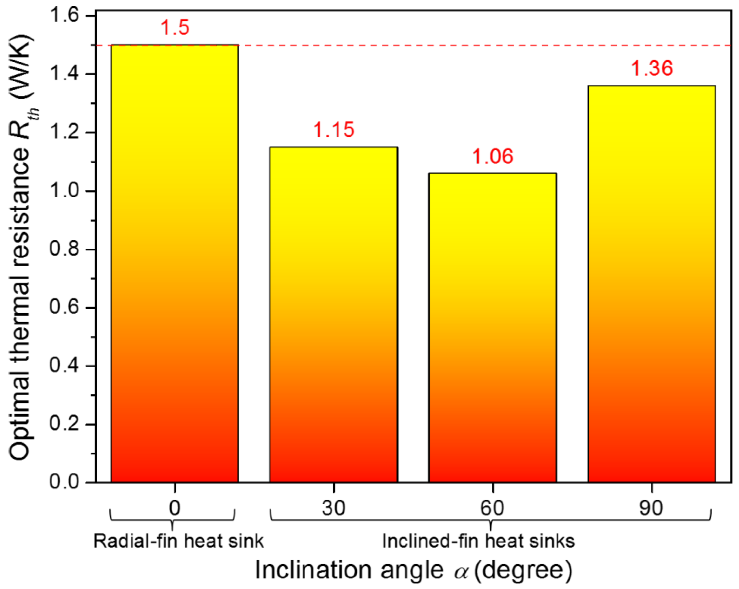
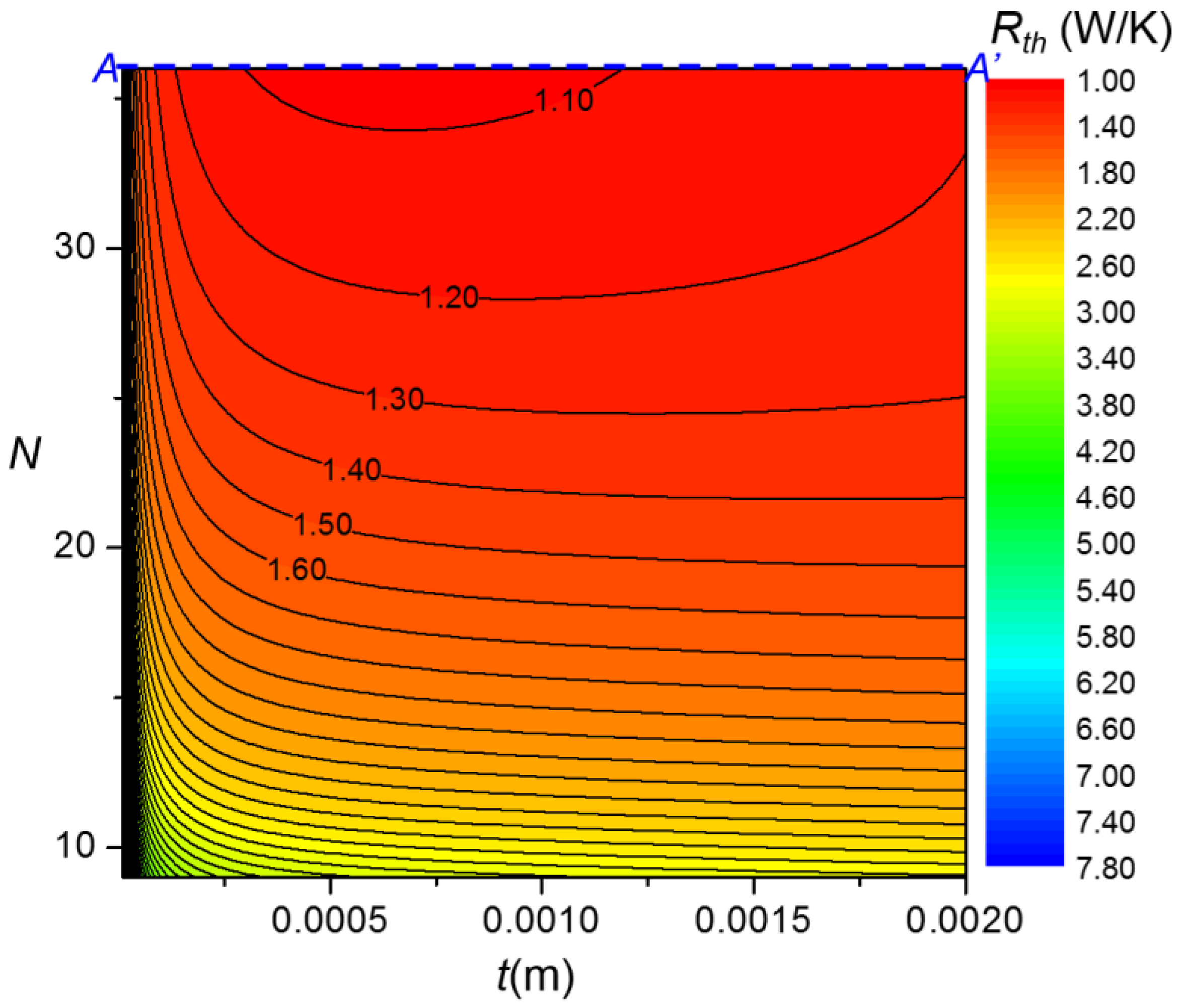
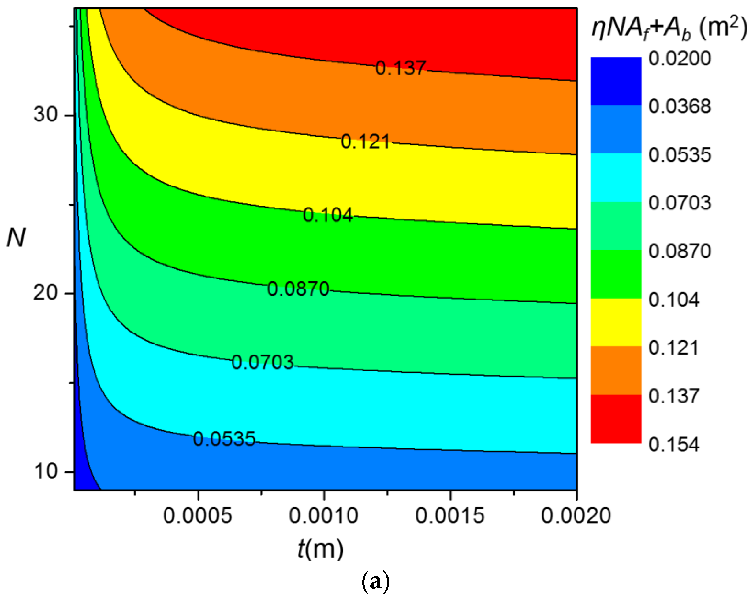
3. Results and Discussion

The difference between the heat sink base temperature (Tw) and the ambient temperature (Tamb) for various inclination angles (α), fin numbers (N), and heat inputs (q) is shown in Table 2 and Figure 4. From these experimental data, the thermal resistance of the heat sink can be calculated as
R t h T w T a m b q
In Equation (1), the thermal resistance Rth is defined as the difference between the heat sink base temperature and the ambient temperature per unit heat transfer rate. The calculated thermal resistance values are listed in Table 2. The uncertainties of the calculated thermal resistances are also listed. As shown in Table 2 and Figure 4, the thermal performance of the inclined plate fin heat sink is minimized when α = 60° and N = 36. According to Figure 3 in [15], the thermal resistance of the conventional radial plate fin heat sink is also minimized when N = 36. In Figure 5, the minimal resistances measured from the inclined plate fin heat sink (α = 60°, N = 36) in the present study are compared with those from the radial plate fin heat sink (N = 36) in [15]. Figure 5 shows that the inclined plate fin heat sink has thermal resistances up to 10% lower than those of the radial plate fin heat sink.
On the basis of the fin model, the thermal resistance can be calculated as follows:
R t h = 1 h ( η N A f + A b )
where η, h, Af, and Ab are the fin efficiency, heat transfer coefficient, fin surface area, and unfinned surface area, respectively.
η = ( h p k s A c ) 0.5 h A f t a n h ( h p k s A c H f ) + ( h / h p k s A c k s ) 1 + ( h / h p k s A c k s ) t a n h ( h p k s A c H f )
h = N u D h k f / D h
A b = π D L N L t
A f = 2 H f L + 2 H f t + L t
Here, Ac and p are the fin cross-sectional area and fin perimeter, respectively.
A c = L t
p = 2 L + 2 t
The fin height Hf is given as a function of α, D, and H:
H f = D 2 cos 2 α / 4 + H 2 + H D D cos α / 2
Dh is the hydraulic diameter of the channel between two adjacent fins, i.e., the yellow region in Figure 2b, and can be calculated from the area Ach and the wetted perimeter pch of the channel:
D h = 4 A c h p c h = 4 ( π ( H + D / 2 ) 2 / N π ( D / 2 ) 2 / N H f t ) 2 H f + 2 π R / N t
The Nusselt number NuDh can be calculated from Equations (2)–(10) once the thermal resistance is obtained from the experimental data. The calculated Nusselt numbers are listed in Table 2.
In the present study, the Nusselt number correlation, which match best with the experimental data, is developed. In the case of the heat sinks with vertical fins under natural convection, the Nusselt number correlations were generally developed as functions of a Rayleigh number RaDh. For example, Welling and Woodridge [8] suggested a Nusselt number correlation for rectangular vertical fins on the flat surface in the form of
N u D h = f ( R a D h )
where the Rayleigh number RaDh is defined as
R a D h = g β f ( T w T a m b ) D h 4 ν f α f L
Similarly, Karagiozis et al. [18] used the average fin spacing as the hydraulic diameter, and suggested a correlation for triangular vertical fins on the flat surface in the form of Equation (11). In the present study, to reflect the effect of the inclination angle on the heat transfer coefficient, the Equation (11) is modified as
N u D h = f ( R a D h , α )
Here, g, βf, νf, and αf are the gravitational acceleration, volume expansion coefficient of fluid, kinematic viscosity of fluid, and thermal diffusivity of fluid, respectively. We tested various functional forms for the function f in Equation (13), and finally found that the functional form
N u D h = C 1 + C 2 l n ( R a D h ) + ( C 3 + C 4 α + C 5 α 2 ) l n ( R a D h ) 2
is matched best with the experimental data. The best empirical coefficients for predicting the Nusselt numbers are determined using a least-squares fit on the experimental data:
C 1 = 2.41 , C 2 = 0.926 , C 3 = 0.120 , C 4 = 7.72 10 4 , C 5 = 8.24 10 6
Finally, the correlation of the Nusselt number for the vertical cylinders with inclined plate fins under natural convection is given as
N u D h = 2.41 0.926 l n ( R a D h ) + ( 0.120 + 7.72 10 4 α 8.24 10 6 α 2 ) l n ( R a D h ) 2
In Figure 6, the Nusselt numbers calculated from Equation (16) are compared with those obtained from experimental data for various Rayleigh numbers. Figure 6 shows that the Nusselt number correlation is in good agreement with the experimental data within a ± 10% error. This correlation is valid in the ranges 100,000 < RaDh < 600,000, 9 < N < 36, and 30° < α < 90°, within which the experimental data were obtained. In addition, though the correlation is developed only for the inclined fin heat sinks, this correlation can predict the Nusselt numbers of the radial fin heat sinks (α = 0) within a ± 30% error (Appendix B).
The thermal resistances of the heat sinks are predicted using the proposed correlations and are compared with the experimental data in Figure 7 and Figure 8. The results from the correlation match the experimental data well within a ±15% error. Figure 7 and Figure 8 present the thermal resistances for various fin numbers and inclination angles, respectively.
In Figure 7, as the fin number increases, the thermal resistance decreases. It is mainly because the fin surface area increases as the fin number increases. As shown in Figure 8, the thermal resistance is minimized when the inclination angle is 60°. Thermal resistance of the inclined fin heat sink with the inclination angle of 60° is smaller than that of 30°, because the fin surface area is greater. The inclined fin heat sink with the inclination angle of 60° has slightly smaller thermal resistance compared to that of 90°. It is because the amount of heat transfer suppression caused by the boundary layer overlap decreases with an increase in the fin-to-fin spacing [15] and the fin-to-fin spacing of the inclined fin heat sink with the inclination angle of 60° is larger than that of 90°. Next, a contour map that depicts the thermal resistance as a function of the fin number and fin thickness by using the proposed correlation is presented in Figure 9. This contour map covers the range of 9 < N < 36, within which the experimental data were obtained. The contour map shows that the thermal resistance decreases as the fin number decreases. This is because, as the fin number increases, the effective surface area, ηNAf + Ab, of the heat sink increases rapidly (Figure 10a), while the heat transfer coefficient h decreases slowly (Figure 10b). At the maximum fin number (N = 36, along the line AA’ in Figure 9), the thermal resistance is minimized at a certain fin thickness. This is because, when N = 36, as the fin thickness increases, the heat transfer coefficient h decreases (Figure 10b), whereas the fin efficiency and the effective surface area (ηNAf + Ab) increase (Figure 10a). Finally, Figure 9 shows that a thermal resistance of 1.06 K/W can be achieved by optimizing the fin number and fin thickness of the inclined plate fin heat sink in the range of 9 < N < 36. For comparison, a contour map of the thermal resistances of cylinders with conventional radial plate fins, which are calculated from the Nusselt number correlation [15], is presented in Figure 11. It shows that the optimal thermal resistance is 1.50 K/W for the heat sink with radial plate fins.
Finally, the thermal resistances of cylinders with inclined plate fins and conventional radial plate fins, which are optimized in the range of 9 < N < 36, are compared in Figure 12. This figure clearly shows that the thermal resistance of the optimized inclined plate fin heat sink with the inclination angle of 60° is 29.3% lower than that of the optimized radial plate fin heat sink. Therefore, we can conclude that cylinders with inclined plate fins perform better than those of cylinders with radial plate fins.

4. Conclusions

In the present paper, natural convection from vertical cylinders with inclined plate fins is investigated experimentally. Experimental investigations are performed for various inclination angles, fin numbers, and base temperatures. Although its applicability is limited to certain specific ranges (100,000 < RaDh < 600,000, 9 < N < 36, and 30° < α < 90°), the suggested correlation enables easy thermal performance calculation. Using the proposed correlation, a contour map depicting the thermal resistance as a function of the fin number and fin thickness is presented. Finally, the optimal thermal resistances of cylinders with inclined plate fins and conventional radial plate fins are compared. It is found that that the optimal thermal resistance of the cylinder with inclined fins is 30% lower than that of the cylinder with radial plate fins. Therefore, inclined plate fins have potential for use in cooling equipment in various thermal systems.

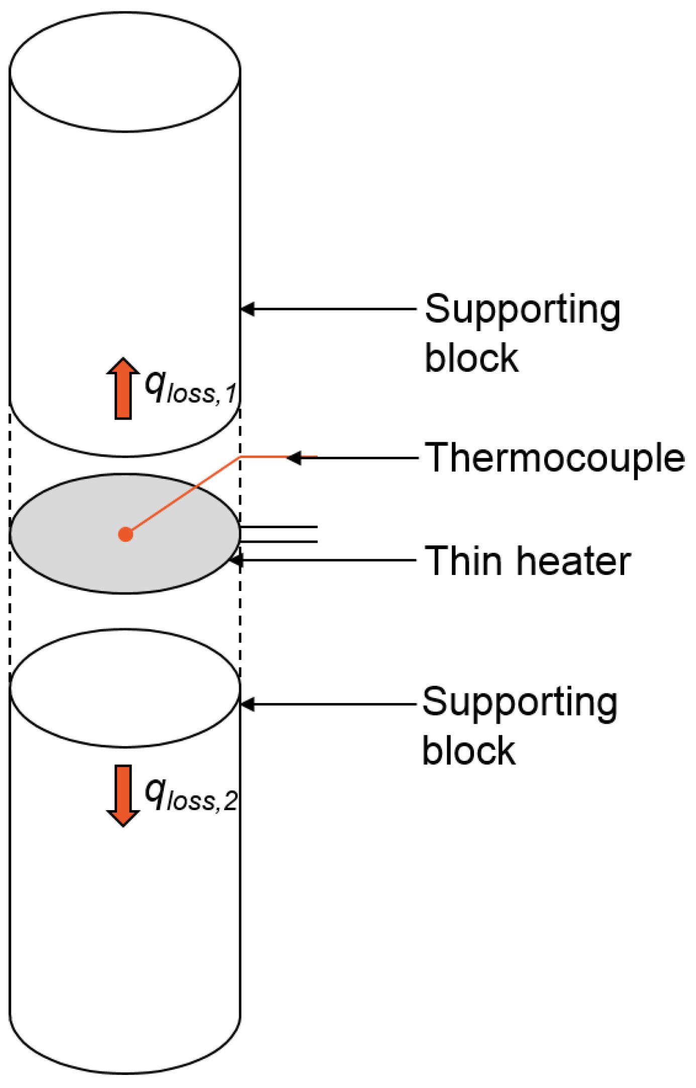
Appendix A. Measurement of the Heat Loss through the Supporting Blocks

The measurement of the heat loss is similar to that written in Reference [15]. For measuring the heat loss, instead of the heat sink, a slim cylindrical heater is sandwiched by the supporting blocks as shown in Figure A1. In this situation, all of the heat produced by the heater is released to the surroundings through the supporting blocks. Therefore, the heat loss through the supporting blocks (qloss,1 + qloss,2) can be measured by measuring the power supplied to the heater. In the present study, the heat loss was measured for various heater temperatures and was used to calculate the actual heat transfer rate to the heat sink.
Figure A1. Schematic diagram of experimental setup for heat loss measurement.
Energies 09 00391 g013

Appendix B. Comparison of Nusselt Numbers for the Radial Heat Sinks Calculated Using the Proposed Correlation and Those from Experimental Data

In Figure B1, the Nusselt numbers calculated from the correlation (Equation (16)) are compared with those obtained from experimental data for the radial plate fin heat sinks presented in Reference [15]. As shown in Figure B1, the correlation can predict the Nusselt numbers of the radial fin heat sinks within a ±30% error, despite the fact that the correlation is developed only for the inclined fin heat sinks. For predicting the Nusselt numbers for both of the inclined fin heat sinks and the radial fin heat sinks, we developed an alternative correlation as follows:
N u D h = 6.21 1.90 l n ( R a D h ) + 0.19 l n ( R a D h ) 2
In Figure B2, the Nusselt numbers calculated from the correlation (Equation (B1)) are compared with those obtained from experimental data for the radial plate fin heat sinks and the inclined fin heat sinks. As shown in Figure B2, the correlation can predict the Nusselt numbers of the radial plate fin heat sinks and the inclined fin heat sinks within a ±15% error. Therefore, we suggest the use of Equation (16) for the accurate prediction of Nusselt numbers for the inclined fin heat sinks (30° < α < 90°), and Equation (B1) can be used for the prediction of Nusselt numbers for both of the radial fin heat sinks and the inclined fin heats sinks.
Figure B1. Nusselt numbers for radial fin heat sinks calculated using proposed correlation and those from experimental data [15].
Energies 09 00391 g014
Figure B2. Nusselt numbers calculated using alternative correlation and those from experimental data.
Energies 09 00391 g015

Acknowledgments

This research was supported by the Nano Material Technology Development Program through the National Research Foundation of Korea (NRF), funded by the Ministry of Science, ICT and Future Planning (NRF-2011-0030285). This work was supported by “Human Resources Program in Energy Technology” of the Korea Institute of Energy Technology Evaluation and Planning (KETEP), granted financial resource from the Ministry of Trade, Industry & Energy, Republic of Korea. (Project No.: 2015 4010 200820).

Author Contributions

Jong Bum Lee and Dong-Kwon Kim conceived and designed the experiments; Sang Woo Lee performed the experiments; Hyun Jung Kim and Dong-Kwon Kim analyzed the data; Dong-Kwon Kim wrote the paper.

Conflicts of Interest

The authors declare no conflict of interest.

References

  1. Oktay, S.; Hannemann, R.J.; Bar-Cohen, A. High Heat from a Small Package. Mech. Eng. 1986, 108, 36–42. [Google Scholar]
  2. Bar-Cohen, A. Thermal Management of Electric Components with Dielectric Liquids. JSME Int. J. Fluids Therm. Eng. 1993, 36, 1–25. [Google Scholar] [CrossRef]
  3. Pop, E. Energy dissipation and transport in nanoscale devices. Nano Res. 2010, 3, 147–169. [Google Scholar] [CrossRef]
  4. Park, J.; Shin, M.; Lee, C.C. Measurement of temperature profiles on visible light-emitting diodes by use of a nematic liquid crystal and an infrared laser. Opt. Lett. 2004, 29, 2656–2658. [Google Scholar] [CrossRef] [PubMed]
  5. Luo, X.; Liu, S. A microjet array cooling system for thermal management of high-brightness LEDs. IEEE Trans. Adv. Packag. 2007, 30, 475–484. [Google Scholar] [CrossRef]
  6. Incropera, F.P. Convection Heat Transfer in Electronic Equipment Cooling. J. Heat Transf. 1988, 110, 1097–1111. [Google Scholar] [CrossRef]
  7. Nakayama, W. Thermal Management of Electronic Equipment: A Review of Technology and Research Topics. Appl. Mech. Rev. 1986, 39, 1847–1868. [Google Scholar] [CrossRef]
  8. Welling, J.R.; Wooldridge, C.B. Free Convection Heat Transfer Coefficients from Rectangular Vertical Fins. J. Heat Transf. 1965, 87, 439–444. [Google Scholar] [CrossRef]
  9. Martynenko, O.G.; Khramtsov, P.P. Free-Convective Heat Transfer; Springer: New York, NY, USA, 2005. [Google Scholar]
  10. Raithby, G.D.; Hollands, K.G.T. Natural Convection. In Handbook of Heat Transfer, 3rd ed.; Rohsenow, W.M., Hartnett, J.P., Cho, Y.I., Eds.; McGraw-Hill: New York, NY, USA, 1998. [Google Scholar]
  11. Sparrow, E.M.; Bahrami, P.A. Experiments on Natural Convection Heat Transfer on the Fins of a Finned Horizontal Tube. Int. J. Heat Mass Transf. 1980, 23, 1555–1560. [Google Scholar] [CrossRef]
  12. Chen, H.-T.; Chou, J.-C. Investigation of Natural-Convection Heat Transfer Coefficient on a Vertical Square Fin of Finned-Tube Heat Exchangers. Int. J. Heat Mass Transf. 2006, 49, 3034–3044. [Google Scholar] [CrossRef]
  13. Yildiz, Ş.; Yüncü, H. An Experimental Investigation on Performance of Annular Fins on a Horizontal Cylinder in Free Convection Heat Transfer. Heat Mass Transf. 2004, 40, 239–251. [Google Scholar] [CrossRef]
  14. Hahne, E.; Zhu, D. Natural Convection Heat Transfer on Finned Tubes in Air. Int. J. Heat Mass Transf. 1994, 37, 59–63. [Google Scholar] [CrossRef]
  15. An, B.H.; Kim, H.J.; Kim, D.-K. Nusselt Number Correlation for Natural Convection from Vertical Cylinders with Vertically Oriented Plate Fins. Exp. Therm. Fluid Sci. 2012, 41, 59–66. [Google Scholar] [CrossRef]
  16. Takeishi, K.; Oda, Y.; Miyake, Y.; Motoda, Y. Convective Heat Transfer and Pressure Loss in Rectangular Ducts With Inclined Pin-Fin on a Wavy Endwall. J. Eng. Gas Turbines Power 2013, 135, 061902. [Google Scholar] [CrossRef]
  17. Hagote, R.B.; Dahake, S.K. Study of Natural Convection Heat Transfer on Horizontal, Inclined and Vertical Heated Plate by V-Fin Array. Int. J. Sci. Eng. Res. 2014, 5, 1366–1374. [Google Scholar]
  18. Karagiozis, A.; Raithby, G.D.; Hollands, K.G.T. Natural Convection Heat Transfer from Arrays of Isothermal Triangular Fins in Air. J. Heat Transf. 1994, 116, 105–111. [Google Scholar] [CrossRef]
Figure 1. Cylindrical heat sink with radial plate fins.
Energies 09 00391 g001
Figure 2. Cylindrical heat sink with inclined plate fins. (a) schematic diagram; (b) top view.
Energies 09 00391 g002
Figure 3. Experimental setup. (a) photograph of a heat sink assembly; (b) schematic diagram of experimental apparatus; (c) photograph of experimental apparatus; (d) positions of thermocouples.
Energies 09 00391 g003
Figure 4. Temperature differences for various fin numbers, inclination angles, and heat inputs.
Energies 09 00391 g004
Figure 5. Comparison of experimental data for minimal resistances between the inclined fin heat sink and the radial fin heat sink (H = 30 mm, N = 36).
Energies 09 00391 g005
Figure 6. Nusselt numbers calculated using proposed correlation and those from experimental data.
Energies 09 00391 g006
Figure 7. Thermal resistances for various fin numbers.
Energies 09 00391 g007
Figure 8. Thermal resistances for various inclination angles.
Energies 09 00391 g008
Figure 9. Contour map of thermal resistance for various fin numbers and fin thicknesses (H = 30 mm, D = 60 mm, L = 50 mm, α = 60°, Tw − Tamb = 50 °C, kf = 0.026 W/m K, ks = 220 W/m K, νf = 1.6 × 10⁻⁵ m2/s, αf = 2.23 × 10⁻⁵ m2/s, βf = 0.0033/K).
Energies 09 00391 g009
Figure 10. Contour maps of (a) effective surface area and (b) heat transfer coefficient for various fin numbers and fin thicknesses (H = 30 mm, D = 60 mm, L = 50 mm, α = 60°, TwTamb = 50 °C, kf = 0.026 W/m K, ks = 220 W/m K, νf = 1.6 × 10⁻⁵ m2/s, αf = 2.23 × 10⁻⁵ m2/s, βf = 0.0033/K).
Energies 09 00391 g010aEnergies 09 00391 g010b
Figure 11. Contour map of thermal resistance of the cylinder with conventional radial plate fins for various fin numbers and fin thicknesses for (H = 30 mm, D = 60 mm, L = 50 mm, Tw − Tamb = 50 °C, kf = 0.026 W/m K, ks = 220 W/m K, νf = 1.6 × 10⁻⁵ m2/s, αf = 2.23 × 10⁻⁵ m2/s, βf = 0.0033/K).
Energies 09 00391 g011
Figure 12. Comparison of the thermal resistances between the optimized inclined fin heat sinks and the optimized radial fin heat sink (9 < N < 36, t < 2 mm, H = 30 mm, D = 60 mm, L = 50 mm, TwTamb = 50 °C, kf = 0.026 W/m K, ks = 220 W/m K, νf = 1.6 × 10⁻⁵ m2/s, αf = 2.23 × 10⁻⁵ m2/s, βf = 0.0033/K).
Energies 09 00391 g012
Table 1. Geometric configuration of tested heat sinks.
NumberNα (°)H (mm)D (mm)L (mm)T (mm)
Heat sink 19303060501.0
Heat sink 212
Heat sink 318
Heat sink 436
Heat sink 5960
Heat sink 612
Heat sink 718
Heat sink 836
Heat sink 9990
Heat sink 1012
Heat sink 1118
Table 2. Thermal resistances and Nusselt numbers calculated from experimental data.
Numberα (°)Nq (W)Tw − Tamb (K)Rth (K/W)NuDh
13092.15 ± 0.0610.1 ± 0.84.69 ± 0.49.13 ± 0.78
4.94 ± 0.1119.9 ± 1.34.04 ± 0.2710.6 ± 0.71
8.26 ± 0.1231.2 ± 0.83.78 ± 0.1111.32 ± 0.33
11.29 ± 0.0539.6 ± 0.73.51 ± 0.0712.19 ± 0.23
14.79 ± 0.0750.8 ± 0.93.44 ± 0.0612.45 ± 0.23
230122.46 ± 0.019.8 ± 0.53.98 ± 0.216.77 ± 0.36
6.16 ± 0.0121.2 ± 0.53.44 ± 0.097.86 ± 0.2
9.7 ± 0.0130 ± 0.53.1 ± 0.058.72 ± 0.15
14.34 ± 0.1339.8 ± 1.52.78 ± 0.119.72 ± 0.38
18.22 ± 0.1949.7 ± 0.82.73 ± 0.059.89 ± 0.19
330183.77 ± 0.2310.8 ± 0.62.85 ± 0.244.7 ± 0.4
8.75 ± 0.4520.5 ± 12.34 ± 0.165.72 ± 0.4
14.5 ± 0.2930.2 ± 0.82.08 ± 0.076.44 ± 0.22
20.47 ± 0.4440.2 ± 0.81.96 ± 0.066.83 ± 0.2
26.91 ± 0.0750.4 ± 11.87 ± 0.047.16 ± 0.14
430364.82 ± 0.0910.8 ± 0.52.25 ± 0.121.6 ± 0.08
11.71 ± 0.0719.4 ± 0.71.65 ± 0.062.17 ± 0.08
22.32 ± 1.5330.6 ± 1.81.37 ± 0.122.62 ± 0.23
30.71 ± 0.6840 ± 0.81.3 ± 0.042.76 ± 0.08
41.52 ± 0.5149.1 ± 0.61.18 ± 0.023.04 ± 0.05
56092.56 ± 0.0110.4 ± 0.54.07 ± 0.27.69 ± 0.38
6.11 ± 0.0420.5 ± 0.53.36 ± 0.099.31 ± 0.24
9.3 ± 0.0330 ± 0.63.22 ± 0.069.71 ± 0.19
14.09 ± 0.0540.8 ± 0.92.89 ± 0.0610.81 ± 0.23
18.15 ± 0.0351 ± 0.62.81 ± 0.0311.13 ± 0.13
660123.05 ± 0.0210.1 ± 0.53.33 ± 0.175.81 ± 0.3
7.42 ± 0.0220.3 ± 0.62.74 ± 0.087.05 ± 0.19
11.55 ± 0.0329.3 ± 0.62.54 ± 0.057.61 ± 0.15
17.14 ± 0.0440.3 ± 0.62.35 ± 0.048.22 ± 0.13
22.35 ± 0.0250 ± 0.52.24 ± 0.028.64 ± 0.09
760184.24 ± 0.0210.2 ± 0.52.42 ± 0.133.87 ± 0.21
10.67 ± 0.2120.5 ± 0.61.92 ± 0.074.88 ± 0.17
16.57 ± 0.0330.2 ± 0.61.82 ± 0.045.13 ± 0.1
23.15 ± 0.0539.9 ± 0.71.72 ± 0.035.43 ± 0.1
31.6 ± 0.0450.6 ± 0.71.6 ± 0.025.83 ± 0.08
860364.91 ± 0.0610.1 ± 0.52.06 ± 0.111.16 ± 0.06
12.57 ± 0.0219.9 ± 0.51.59 ± 0.041.51 ± 0.04
21.51 ± 0.0730 ± 0.61.39 ± 0.031.72 ± 0.03
31.78 ± 0.4340.1 ± 0.51.26 ± 0.021.9 ± 0.04
43.55 ± 0.3450.4 ± 0.61.16 ± 0.022.07 ± 0.03
99092.48 ± 0.0410 ± 0.64.04 ± 0.264.8 ± 0.31
5.68 ± 0.0219.5 ± 0.53.43 ± 0.095.64 ± 0.15
9.4 ± 0.0329.6 ± 0.63.15 ± 0.066.16 ± 0.12
13.88 ± 0.0340.5 ± 0.62.92 ± 0.046.63 ± 0.1
17.95 ± 0.0250.7 ± 0.52.83 ± 0.036.85 ± 0.07
1090123.02 ± 0.019.6 ± 0.53.18 ± 0.173.66 ± 0.2
7.32 ± 0.0420.7 ± 0.72.83 ± 0.14.11 ± 0.14
11.23 ± 0.0628.9 ± 0.92.58 ± 0.084.52 ± 0.14
16.16 ± 0.0538.7 ± 0.82.4 ± 0.054.85 ± 0.1
21.93 ± 0.0649.2 ± 0.82.24 ± 0.045.19 ± 0.09
1190183.83 ± 0.039.9 ± 0.62.58 ± 0.152.1 ± 0.12
10.42 ± 021.9 ± 0.52.1 ± 0.052.58 ± 0.06
16.7 ± 0.0331.7 ± 0.61.9 ± 0.042.86 ± 0.05
23.1 ± 0.1841.2 ± 0.61.78 ± 0.033.04 ± 0.05
30.48 ± 0.3350.9 ± 0.61.67 ± 0.033.25 ± 0.05

