1. Introduction
In many industrial facilities, waste heat represents a significant source of energy, some of which might be recovered to reduce primary energy use. The recovery of waste heat has the potential both to improve industrial competitiveness and reduce environmental impact. Bendig
et al. [
1] draw an analogy between industrial waste heat and natural resources by distinguishing between
reserves and
resources. The distinction is useful since it encourages engineers to minimise avoidable waste heat before considering economic use of the reserves that remain.
Of the energy that enters an industrial process, some is used effectively for production; some is lost in conversion inefficiencies, while the remainder is rejected, mostly in the form of waste heat. Researchers have tried to quantify the energy that is used effectively by considering the “thermodynamic minimum” energy required to produce a unit of product [
2], which is usually far less than the input energy for practical processes. For this reason, a primary important goal for industrial energy managers is the avoidance of waste process heat. A secondary goal is the recovery of as much of the unavoidable waste heat as is practical, preferably on site. Once opportunities for economic onsite recovery have been exhausted, then opportunities for offsite recovery should be examined [
3,
4]. A power system based on the organic Rankine cycle (ORC) may be used to convert low grade heat into electricity. This can be used either to offset an industrial site’s electricity demand or it may be fed into an electricity grid to generate a financial return. There is considerable interest in the organic Rankine cycle since this technology represents a flexible and relatively efficient means of generating a benefit from waste heat [
5,
6,
7,
8].
Organic Rankine cycle systems operate in a similar manner to turbines based on the familiar steam Rankine cycle, except that, instead of water, an ORC device uses one of a wide range of organic chemicals as the working fluid. The choice of working fluid is influenced by many factors including toxicity, environmental impact in case of accidental release, stability, cost and thermodynamic properties over the range of temperatures and pressures experienced in the application. For some fluids, the temperature at which heat is input to the evaporation part of the cycle may be as low as 73.3
C [
6] while for others it may be as high as 340
C [
9]. Suitable working fluids for ORC include linear, branched and aromatic hydrocarbons, fluorinated hydrocarbons, siloxanes, ethers and alcohols. The range of ORC working fluids available is so wide that there have been many studies into their selection methods and the corresponding choice of expander type such as radial inflow turbine, scroll expander and screw expander. Such studies cover pure fluids as well as mixtures, the latter having the advantage that heat can be supplied and rejected over a wider range of temperatures while working pressure remains constant. Researchers also report ORC performance according to different criteria including first law efficiency, second law efficiency, work output, and exergy efficiency [
10]. Selection of a suitable working fluid is usually carried out by modelling the thermodynamic cycle of the ORC and its ancillary equipment, then running the model under different conditions and with different working fluids whose properties have been tabulated. One such study concludes with the general guidelines that to maximise net ORC power output, a working fluid should be chosen with a critical temperature 30–50 K above the heat source temperature for pure fluids, and 30–50 K below the heat source temperature for mixtures [
11].
The wide range of suitable working temperatures means that ORC power systems can be used to generate electricity from a wide range of heat sources and with varying temperatures, including diesel exhaust systems, cement kilns, steel furnaces [
12], biomass combustion, solar thermal collectors and geothermal boreholes [
8]. In industrial systems, one of the reasons for a wide variation in hot source temperature is the cyclic nature of many industrial processes in which material is loaded into a vessel before heating, cooling and unloading ready for the next cycle. Under such conditions, the temperature of waste process heat will inevitably vary significantly, and the actual performance might be expected to differ significantly from predicted performance based on a simulation study. However, by controlling the variations of a real process (apart from ambient temperature which cannot be controlled) and making careful measurements, it has been shown that a model of an ORC supplied by waste industrial process heat can be validated. In the case of waste heat capture from a ceramic process, modelling suggested a net electrical efficiency of 10.88% compared to a maximum measured value of 10.94% [
13].
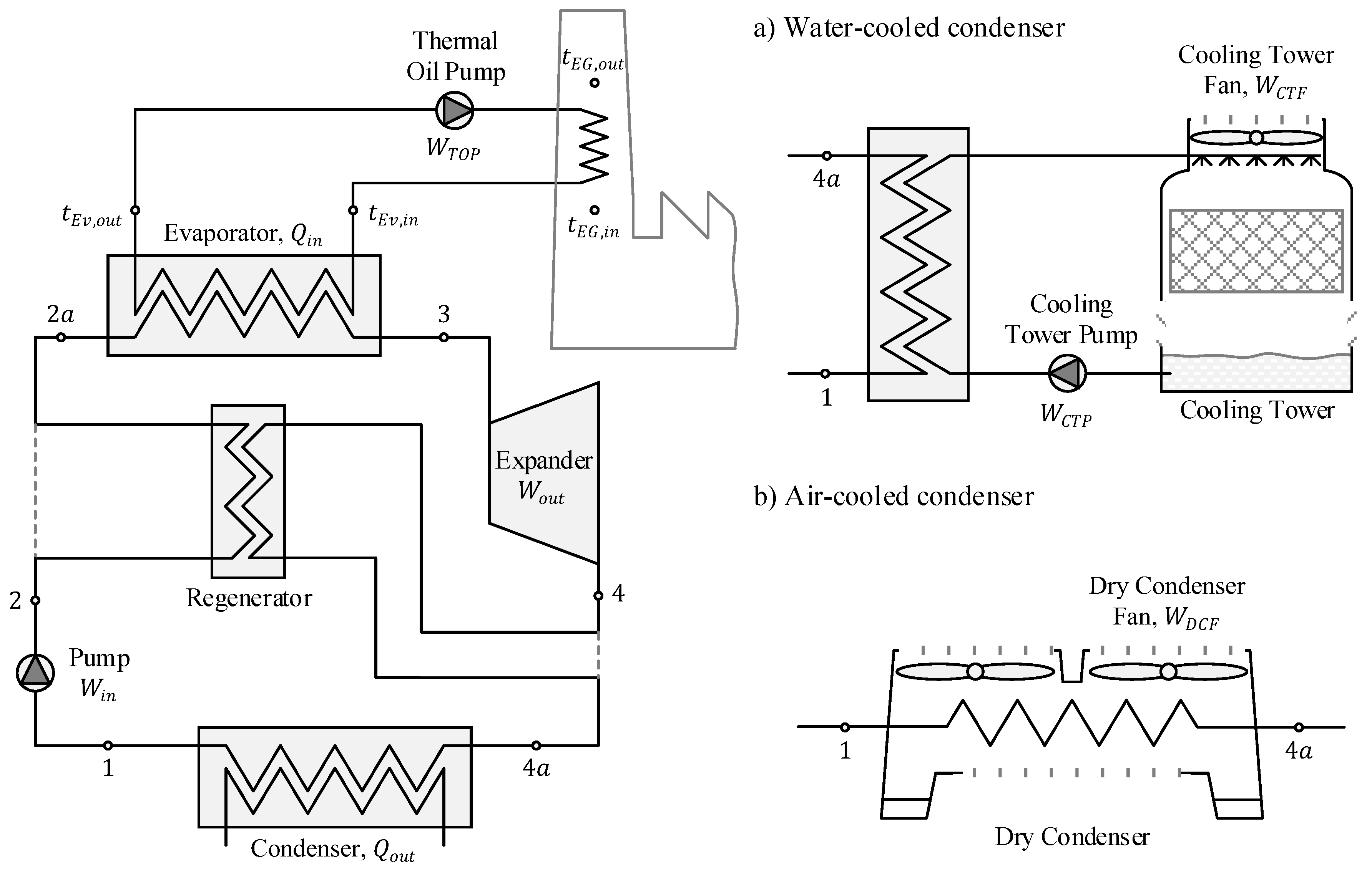
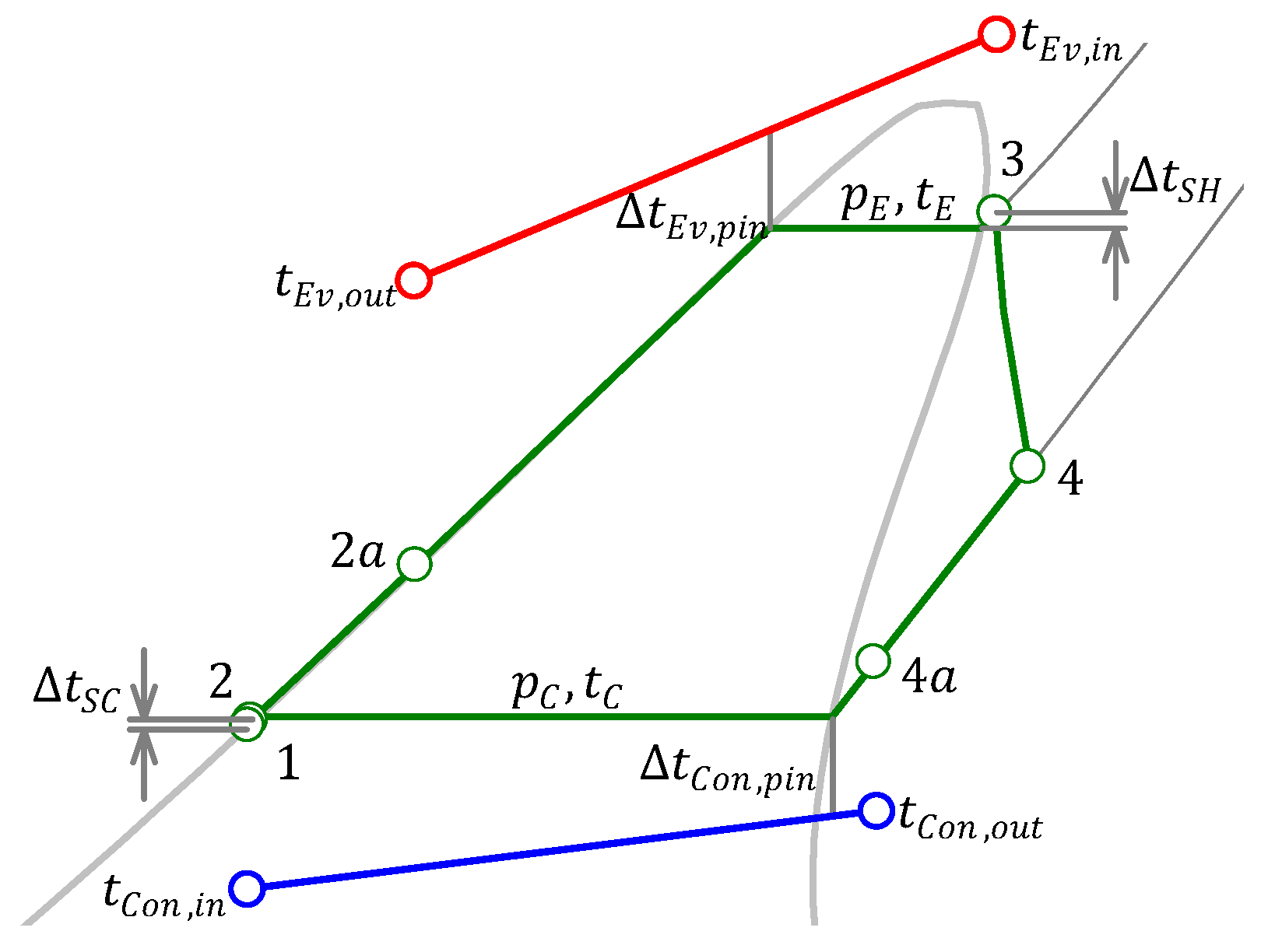
The basic ORC consists of a pump, evaporator, expander and condenser. Many systems also feature a regenerator (sometimes known as an internal heat exchanger) that extracts heat from fluid leaving the expander and uses this to preheat the fluid entering the evaporator (
Figure 1). In the idealised cycle, fluid at state 1 enters the pump where its pressure is increased to the maximum pressure of the cycle before it is heated in an isobaric process, firstly by the regenerator (if present) and then by the evaporator until it reaches the maximum temperature of the cycle at which point it may be superheated. It is then expanded in an expander where the work extracted is used to generate electricity, after which it is cooled firstly in the regenerator (if present) then the condenser, where it is cooled isobarically until it reaches state 1 again. The regenerator is often necessary because for many organic working fluids the temperature of the fluid leaving the expander is significantly higher than that at which it enters the pump [
14]. The ORC may be represented thermodynamically on a temperature entropy diagram as shown in
Figure 2.
As well as the choice of working fluid and the temperatures of the heat source and sink, the performance of an ORC is influenced significantly by the presence and design of the internal heat exchanger, and the design of the external heat exchangers used by the evaporator and condenser. In practical applications, the temperature of the heat source may vary and heat may be available only intermittently, for example waste heat from a batch process [
5].
Unlike the steam Rankine cycle, the evaporator of an ORC may need to be heated indirectly via a thermal oil loop, for example when the heat source is at too high temperature for a flammable working fluid [
14,
15]. Similarly, the heat is rejected from an ORC via a condenser that must be cooled either by water (using a cooling tower) or by air (using a dry condenser) as shown in
Figure 1. The heat from the condenser can also be usefully deployed, for example for district heating or absorption chilling [
9,
16].
A full analysis of ORC system performance should therefore consider the performance of the heat exchangers used in the evaporator, condenser and regenerator as well as any auxiliary power used for pumps and fans, etc. The performance of the condenser itself depends upon the climatic conditions in which it operates, including outdoor air wet-bulb temperature (for a cooling tower) and outdoor air dry-bulb temperature for a dry condenser.
Aim of This Paper
The aim of this paper is to analyse the impact of local climate on the performance of both ORC nominal efficiency and annual ORC system efficiency when driven by waste heat from a foundry.
In this paper, ORC nominal efficiency means the thermodynamic cycle efficiency at nominal operating conditions which are: nominal temperature of waste heat, nominal mass flow rate, and location-specific outdoor air design conditions. The auxiliary energy associated with the condenser and evaporator is not considered in the ORC nominal efficiency computation. In contrast, the annual ORC system efficiency means the annual performance of the whole system, taking into account variability in waste heat availability, hourly variation of a location’s outdoor air temperature as well as energy requirements of pumps and fans in the condenser and evaporator external loops.
2. Modelling the ORC as a Component of an Energy System
In order to model the performance of an ORC in a system for the recovery of industrial waste heat, one must model the operation of heat exchangers as they respond to variations in both input energy and heat rejection. The former is driven by industrial process variability while the latter is driven by the climate. In addition, the thermodynamic properties of a range of potential working fluids must be known.
In general, the performance of the ORC can be determined from the thermodynamic cycle (
Figure 2). The important parameters of the cycle are condensation pressure (
) and evaporation pressure (
). The condensation pressure is determined by the condenser pinch temperature (
). Similarly, the evaporation pressure is determined by the temperature difference at the evaporator pinch point (
); however, it must not exceed the maximum pressure which was chosen to be 90% of the critical pressure [
17,
18]. This limitation can result in operation with a larger than minimum temperature difference at the evaporator pinch point. In this study, the minimum temperature difference for both pinch points was set to 10
C.
Superheating of the working fluid before it enters the expander does not result in a significant increase of the ORC efficiency [
19], and it is not necessary in systems with dry working fluids. However, to reduce damage in practical ORC installations, some superheating is always used to ensure that the vapour enters the expander in the dry state. Similarly, there may be a small amount of subcooling after the condenser to avoid cavitation of the working fluid pump.
Figure 2 shows that, in this study, the temperature at state 3 is chosen to be higher than the evaporation temperature (
) by 5
C (
) while at state 1, the temperature is chosen to be lower than condensation temperature (
) by 3
C (
) [
20].
Additional boundary conditions that determine the performance of the ORC are the isentropic efficiencies of pump and expander. A pump isentropic efficiency (
) of 0.6 and an expander isentropic efficiency (
) of 0.8 were chosen, based on Fernández
et al. [
9].
The efficiency of the ORC system can be improved for some working fluids by using a regenerator [
21]. The superheated working fluid at the expander outlet is cooled in the regenerator, which also preheats the cold condensed liquid leaving the pump before it enters the evaporator. A regenerator effectiveness (
) of 80% was used in this study [
22] which means that states
and
presented in
Figure 2 can be easily determined. The available heat for regeneration is the difference between the enthalpy of superheated vapour at the expander outlet (
in
Figure 2) and either the enthalpy of saturated vapour at condensation pressure or, if temperature of condensed liquid leaving the pump (
in
Figure 2) is above the temperature of condensation, enthalpy of the superheated vapour at condensation pressure and temperature
(Equation (
1)):
The actual regenerated heat is a product of the available heat for regeneration and the regenerator effectiveness (Equation (
2)):
The enthalpies of states
and
, which are required for calculating the heat transfer in the evaporator and condenser respectively, are determined by using the regenerated heat as presented in Equations (
3) and (
4):
The objective of the ORC system is usually to maximise the work output (generated electricity) from the waste heat input. The thermal efficiency of the ORC is calculated by dividing the net mechanical work output by the waste heat input (Equation (
5)). Equation (
5) can also be applied to the cycle without regenerator by replacing
with
:
The ORC system is typically designed to operate with high thermal efficiency at nominal operating conditions. However, the real operating conditions deviate from nominal for much of the time, which means that the system works at part load some of the time, characterised by the part load ratio (PLR). This is particularly true in applications that utilise waste heat from batch processes such as furnace operation in a foundry. Fortunately, a feature of the ORC is operation at high efficiencies over a wide range or PLR [
23]. Quoilin
et al. [
24] show that ORCs are well adapted to waste heat inputs with both variable temperature and mass flow rate only if a proper control strategy is applied. Leading ORC suppliers also claim that the 90% efficiency can be maintained even at 50% load, while the part load operation may be as low as 10% of a nominal [
25,
26]. In this study, the cycle efficiency at part load condition was calculated by multiplying the thermal efficiency at nominal condition with a correction coefficient, which is function of PLR.
2.1. Waste Heat Available From a Foundry
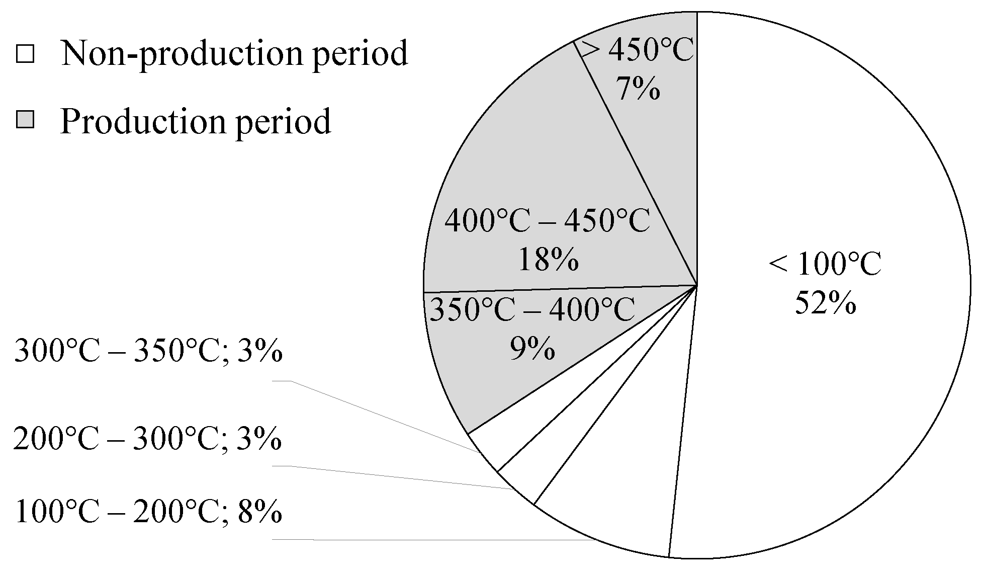
The annual waste heat profile generated for this study is based on 15 weeks of half-hourly data collected between early September and December 2013. Data were collected from the supervisory control and data acquisition (SCADA) system used by the Foundry Company (Rimini, Italy). Waste heat is carried in the exhaust gases that are a product of combustion in a cupola furnace. The initial step in the modelling process was to investigate the distribution of waste heat temperatures.
Figure 3 shows that waste heat temperatures were above or equal to 350
C for just over a third of the monitored period. This was during the production period of the process. For more than half of the monitored period, there was no production at all, while the rest of the time was spent on a system preheating and cooling (when temperatures were between 100 and 350
C).
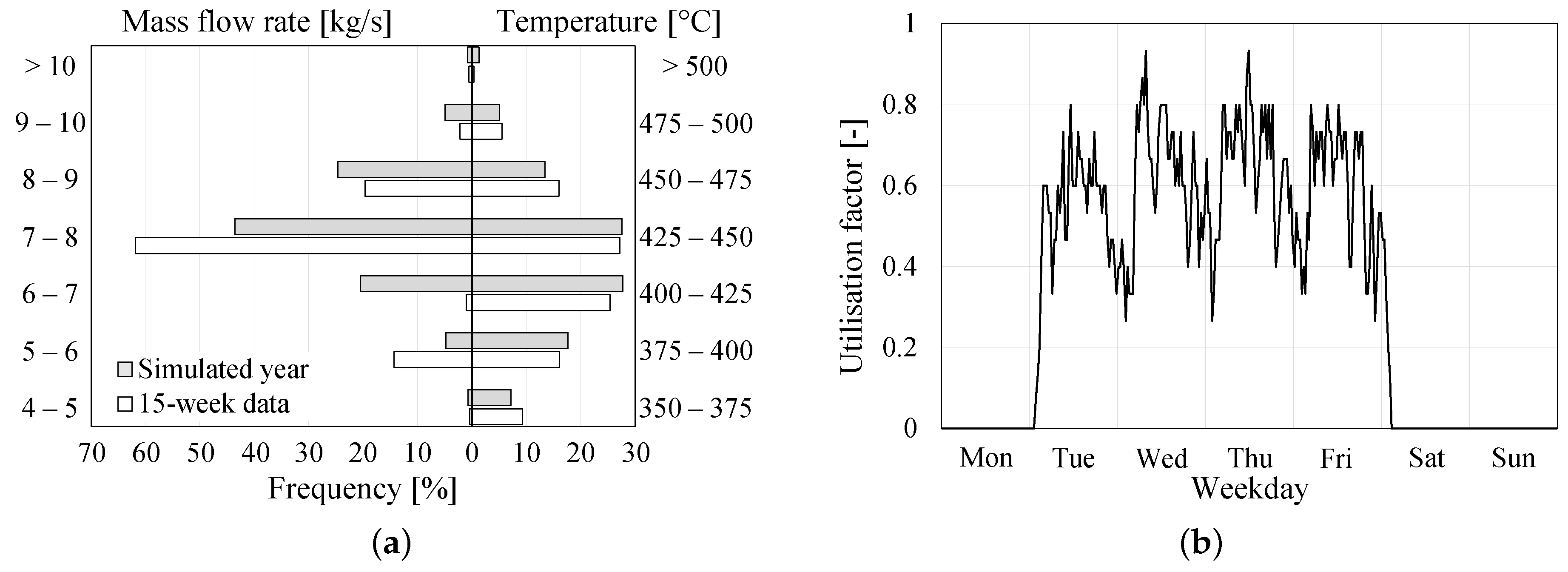
Since the main aim of this paper is to investigate the annual performance of the ORC system, including auxiliary energy requirements, a yearly waste heat profile was developed from the available 15-week data using statistical methods. For both temperature and mass flow rate data, the mean and standard deviation were calculated for each half-hour period in the 15-week dataset, but only including records when the temperature was above 350 C. A 52-week “simulated year” was generated, by calculating the inverse of the normal cumulative distribution for the specified mean and standard deviation with an evenly distributed random probability for each half-hour slot.
Production period waste heat temperature and mass flow rate frequency distribution in percentiles for both simulated year and 15-week data are presented in
Figure 4a. The simulated year data for temperature are a better match for the 15-week data than that for mass flow rate. The reason is that production was reduced for several weeks during the monitoring period and the waste heat flow rate was slightly lower than usual. Another parameter that was obtained from monitored data is the utilisation factor, which shows the presence or absence of production (utilisation = 1 or 0) during each half-hour period over 15 weeks.
Figure 4b shows that there was no single half-hour period in which there was production (hence available waste heat) in every one of the monitored 15 weeks. It also shows that there is no production over a weekend or Monday. The utilisation factor is used to adjust ORC electricity generation calculated from the simulated year.
The variability in waste heat temperatures and mass flow rates over the production period makes the identification of nominal operating conditions slightly more complex. This is an important decision that can affect the initial cost as well as overall system performance. It is unusual to size the equipment based on the maximum available waste heat, which occurs infrequently during the production period. On the other hand, undersizing the equipment leads to wasted generation potential. The nominal operating temperature of waste heat was selected as the 90th percentile of all temperatures during the production period, which is 465 C. The nominal mass flow rate of 8 kg/s was calculated by using the nominal temperature and the 90th percentile of waste exergy.
The choice of the nominal operating conditions is made upon the simplified analysis of the nominal power and available waste heat as a function of nominal waste heat temperature. Analysis of the monitored data (
Figure 4a) shows that for approximately 0.5% of the production period the waste heat temperature and waste heat mass flow rate are above 500
C and 10 kg/s, respectively. The maximum available waste heat was calculated for the maximum recorded waste heat temperature (507
C) and flue gas mass flow rate of 10.2 kg/s. The required nominal system power would be 3.51 MW and it would reclaim 5.68 GWh of thermal energy annually. The nominal operating temperature was chosen as the 90th percentile of all temperatures during production time and represents an operating point that is felt to be a good balance between power output and capture of available waste heat. Specifically, nominal power is reduced by about 31.6% while sacrificing less than 1% of available waste heat. A further 5% reduction in nominal power would be obtained at the 80th temperature percentile, and would represent a loss of waste heat of over 2%. If the nominal temperature was selected at 65th percentile, then a 41.6% smaller system would be required, however, this would be penalised with over 4.5% less waste heat capture.
In real applications, there is a limit on the minimum waste stream temperature, which is often related to material corrosion. It is best to keep the waste stream temperature above the condensation temperature of corrosive elements, which depends on the composition of the exhaust gases. Exhaust from natural gas combustion can be cooled as low as 120
C while exhaust from coal combustion may be limited to 150
C [
27]. In this study, the waste stream leaving temperature (
in
Figure 1) was initially kept above 180
C due to the high concentration of dirty gases which are typical for cupola steelmaking furnaces.
2.2. Modelling the Thermal Oil Loop
A combination of high temperature exhaust gas and flammable working fluid dictates the use of an intermediate heat carrier, in this case thermal oil. The exhaust gas waste heat is transferred to the thermal oil, which is pumped to the ORC evaporator. The thermal oil loop characteristics are defined by the temperature profile of the waste heat source. The temperature of thermal oil leaving the evaporator (
in
Figure 1) was kept above 150
C which is 30
C lower than the minimum waste heat stream temperature. The maximum temperature of thermal oil leaving the waste heat stream and entering the ORC evaporator (
in
Figure 1) is limited by the type of thermal oil used. Mineral based thermal oils can operate with temperatures up to 310
C while synthetic thermal oils can operate with temperatures above 400
C [
28]. The main disadvantage of synthetic thermal oils is their cost. In this study, the thermal oil is assumed to have a maximum temperature of 300
C.
The thermal oil loop component of interest is the pump. We assume that the pump is driven by a variable speed drive for reasons of part load efficiency while maintaining a constant temperature drop in the evaporator
. The nominal volume flow rate
can be determined from nominal heat input
, temperature drop in evaporator, thermal oil density
and specific heat
as presented in Equation (
6):
The nominal volume flow rate was used to calculate the nominal pump power
(Equation (
7)):
where
is the pressure drop in the thermal oil loop (assumed to be 100 kPa based on two heat exchangers), and
and
are pump motor and impeller efficiencies, assumed to be 0.9 and 0.78 respectively. Part load pump power was assumed to be a linear function of the ORC system PLR as presented in Equation (
8):
2.3. Selection of Working Fluids
There have been many studies into the effect of working fluid choice on ORC performance. Fluid parameters that have to be considered include fluid toxicity and flammability as well as thermophysical characteristics including the appropriate evaporation temperature, critical temperature/pressure, density,
etc. [
15]. Moreover, thermoeconomic optimisation does not necessarily lead to the selection of a same working fluid as thermodynamic optimisation [
29].
ORC applications with a maximum working fluid temperature between 180 and 300
C require particularly careful fluid selection [
9]. Today’s high temperature ORC plants mainly use siloxanes and Toluene [
14]. Siloxanes have certain advantages compared to other organic fluids such as low toxicity, low corrosion, limited flammability and good thermal stability [
30]. Three cyclic siloxanes (D
, D
and D
) and four linear siloxanes (MDM, MD
M, MD
M and MD
M) were initially selected for the analysis in this study. Three aromatic fluids were also chosen for comparison (Toluene, o-Xylene and p-Xylene). All working fluids in this study are “dry fluids” and their thermophysical properties were obtained from CoolProp, an open-source thermophysical property library [
31].
2.4. Condenser Type
Since condensation pressure is determined by a condenser pinch point temperature () of 10 C, this imposes a lower limit on the temperature of the condenser heat sink. However, the condenser type also affects the heat sink temperature. The two most typical condenser types are air-cooled and water-cooled, the latter using a cooling tower. The main reason for selecting these two types for comparison is their different impact on ORC efficiency and their auxiliary electricity requirements. In general, an ORC with a water-cooled condenser will always have a higher ORC nominal efficiency than one with an air-cooled condenser, assuming all other parameters are same. However, under certain conditions, a water-cooled condenser may not be cost-effective, for example in a humid climate with moderate air temperature where the small additional benefit of water cooling might be outweighed by the extra cost of the electricity requirements of the cooling tower pump. The auxiliary electricity requirements of both types of condenser are affected by the amount of ORC heat rejection and climate conditions, both of which are highly variable. Condenser auxiliary energy requirements must therefore be considered when the overall ORC efficiency is analysed.
2.4.1. Air-Cooled Condenser
Heat rejection by an air-cooled condenser (
in
Figure 1) is directly proportional to the difference between the condensation temperature (
in
Figure 2) and the outdoor air dry-bulb temperature (
) as presented in Equation (
9), where the parameters
a and
b can be obtained from the equipment manufacturer [
32]:
Equation
9 can be approximated by assuming that the parameter
a is zero, in which case parameter
b can be calculated from the nominal operating conditions for which the nominal heat rejection (
) and the outdoor air dry-bulb temperature
are known. The nominal outdoor air dry-bulb temperature is a characteristic of the location of the ORC system and is usually based on the location’s dry-bulb design day using 0.4% design conditions [
33].
For an air-cooled condenser, auxiliary electricity consumption (
Figure 1b) is due to the condenser fan. Fan nominal power requirements (
) generally range between 20 and 40 W/kW of heat rejection [
33]. The median value of 30 W/kW is used in this study.
Dry condenser fan electricity consumption is determined by the type of fan control at operating conditions other than nominal. This might be: cycling ON/OFF, fixed speed with damper, two-speed or variable speed. A variable speed fan was chosen in this study with the fan power proportional to the cube of the air flow (Equation (
10)):
where
is the air volume ratio calculated from Equation (
11) [
32]:
where
is ORC rejected heat and
is a maximum possible heat rejected by the condenser for off-nominal condition (reduced outdoor air dry-bulb temperature) as presented in Equation (
9).
The final parameter that is required to fully describe an air-cooled condenser in an ORC system is the air temperature rise, which occurs when heat is lost from the ORC working fluid. The typical temperature rise in an air-cooled condenser is between 5 and 17
C [
34] so for the purpose of this study it was fixed at 12
C (
in
Figure 2).
2.4.2. Water-Cooled Condenser
ORC systems with a water-cooled condenser and cooling tower (
Figure 1a) usually operate with lower condensation pressure compared to systems with air-cooled condensers. This is due to heat rejection at a lower temperature. The temperature of water entering the condenser (
in
Figure 2) is the setpoint that the cooling tower has to meet. The theoretical minimum water temperature of a cooling tower is the outdoor air wet-bulb temperature. Cooling tower size is dictated by the choice of leaving water temperature setpoint and it is the reciprocal of the difference between this and outdoor air wet-bulb temperature (so-called cooling tower approach temperature). A large approach temperature results in a small cooling tower; however, it has a negative impact on the ORC condensation pressure. On the other hand, larger cooling towers have higher auxiliary electricity requirements. A well-designed cooling tower can achieve an approach temperature of 2–3
C, although preferred values are 3–7
C [
35]. The nominal approach temperature in this study was chosen as 4
C and it was used to determine cooling tower characteristics at nominal conditions.
As with an air-cooled condenser, the cooling tower is sized based on a location’s nominal outdoor air temperature, in this case the wet-bulb temperature at 0.4% design conditions. This temperature and approach temperature determine the temperature of water entering the condenser. The difference in water temperatures across the tower is the “cooling range”. Cooling range is important for two reasons: it defines the condenser temperature rise and also the size of the cooling tower pump. The cooling range is affected by both the approach temperature and design outdoor air wet-bulb temperature. Once the cooling range is obtained, the cooling tower water flow rate can be calculated (Equation (
12)):
This leads to nominal cooling tower pump power
(Equation (
13)):
where
and
are water density and specific heat respectively,
is nominal heat rejection,
is the pressure drop in the cooling tower loop (assumed to be 100 kPa), while
and
are pump motor and impeller efficiencies (the same as for the thermal oil pump).
The water flow rate in cooling tower systems is usually maintained constant or modulated within tight boundaries (
), which means that its capacity is predominantly controlled by modulating air flow rate either by fan cycling, two-speed fan or variable speed fan. A variable speed fan has been assumed in this study, combined with water flow rate modulation of 25%. The associated fan power consumption, cooling tower range and cooling tower approach temperature are calculated by using an empirical variable speed cooling tower model based on the YorkCalc correlation (Johnson Controls, Inc.: Milwaukee, WI, USA) [
36].
2.5. Selection of Weather Files
As mentioned, the main aim of this paper is to evaluate the ORC nominal efficiency and annual ORC system efficiency when used with waste heat from a foundry that may be located in different climate conditions. For that purpose, 106 locations from the European Economic Area (EEA) are selected (
Figure 5). International Weather for Energy Calculation (IWEC) weather files [
37] for each location are used for evaluating the performance of the ORC.
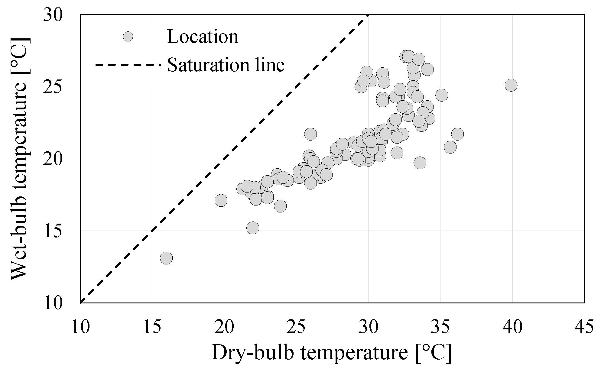
Figure 6 summarises the nominal (design) weather conditions for the selected locations. It can be seen that the nominal outdoor air dry-bulb temperatures range from 16 to 40
C while the nominal outdoor air wet-bulb temperatures range between 13 and 27
C. It also shows an almost linear relation between wet-bulb temperature and dry-bulb temperature for dry-bulb temperatures below 30
C. However, the locations with nominal outdoor air dry-bulb temperature between 30 and 35
C have a wider range of nominal wet-bulb temperature. This can have a crucial impact on the choice of ideal condenser type. Beside the nominal outdoor air temperature, which is of great importance in system sizing, the annual temperature profiles (dry-bulb temperature for air-cooled condenser and wet-bulb temperature for water-cooled condenser) are crucial for the analysis since they directly affect the condenser auxiliary electricity use.
3. Analysis of Results
Consideration of 10 working fluids, 106 locations across Europe, the presence or absence of a regenerator and a choice of two condenser types result in 4240 possible ORC system scenarios. A system model comprising an ORC coupled with a condenser loop and thermal oil loop was developed and run in Python in order to determine both ORC nominal efficiency and annual ORC system efficiency. The analysis has three main parts: ORC nominal efficiency analysis, annual ORC system efficiency analysis, and analysis of the impact of exhaust gas temperature on net electricity generation.
3.1. ORC Nominal Efficiency
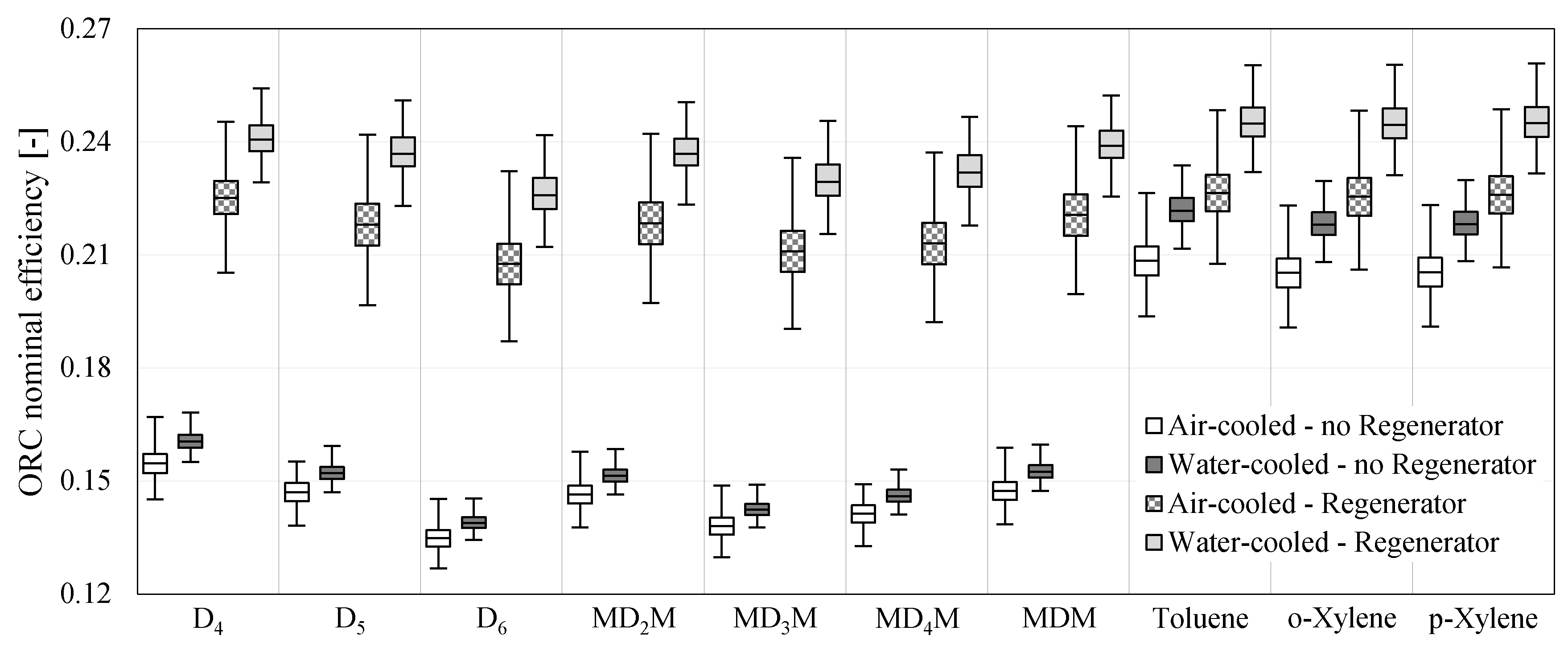
ORC nominal efficiency is evaluated as the thermodynamic cycle performance at nominal operating conditions. Box plots in
Figure 7 represent the distribution of ORC nominal efficiencies across 106 European locations for a system with either an air-cooled or water-cooled condenser and with or without a regenerator. It is clear that, for all working fluids, the ORC nominal efficiency is always higher for a system equipped with a water-cooled condenser than the same system with an air-cooled condenser. In addition, using a regenerator results in increased efficiency in all cases. Another clear finding from the results presented in
Figure 7 is the large spread of ORC nominal efficiencies for air-cooled systems with a regenerator. The spread is over 4% for aromatic hydrocarbons and up to 4.5% for cyclic siloxanes. The main performance difference between siloxanes and aromatic hydrocarbons is that the latter tend to work better in systems with no regenerator. This may be useful to consider when the preliminary decision on system configuration is made, since regenerator systems are more expensive. The overall conclusion is that aromatic hydrocarbons work better than siloxanes when operated within the system boundaries described earlier. However, within each working fluid group analysed the best performer can be clearly identified only in the case of cyclic siloxanes, where it is D
. Among linear siloxanes, MDM and MD
M perform similarly. All three aromatic hydrocarbons are very close to each other. Following a detailed inspection of the modelling outputs, Toluene was identified as the working fluid with the best performance across all locations, regardless of the type of condenser or presence or absence of regenerator. These three working fluids are examined in more detail in the following sections.
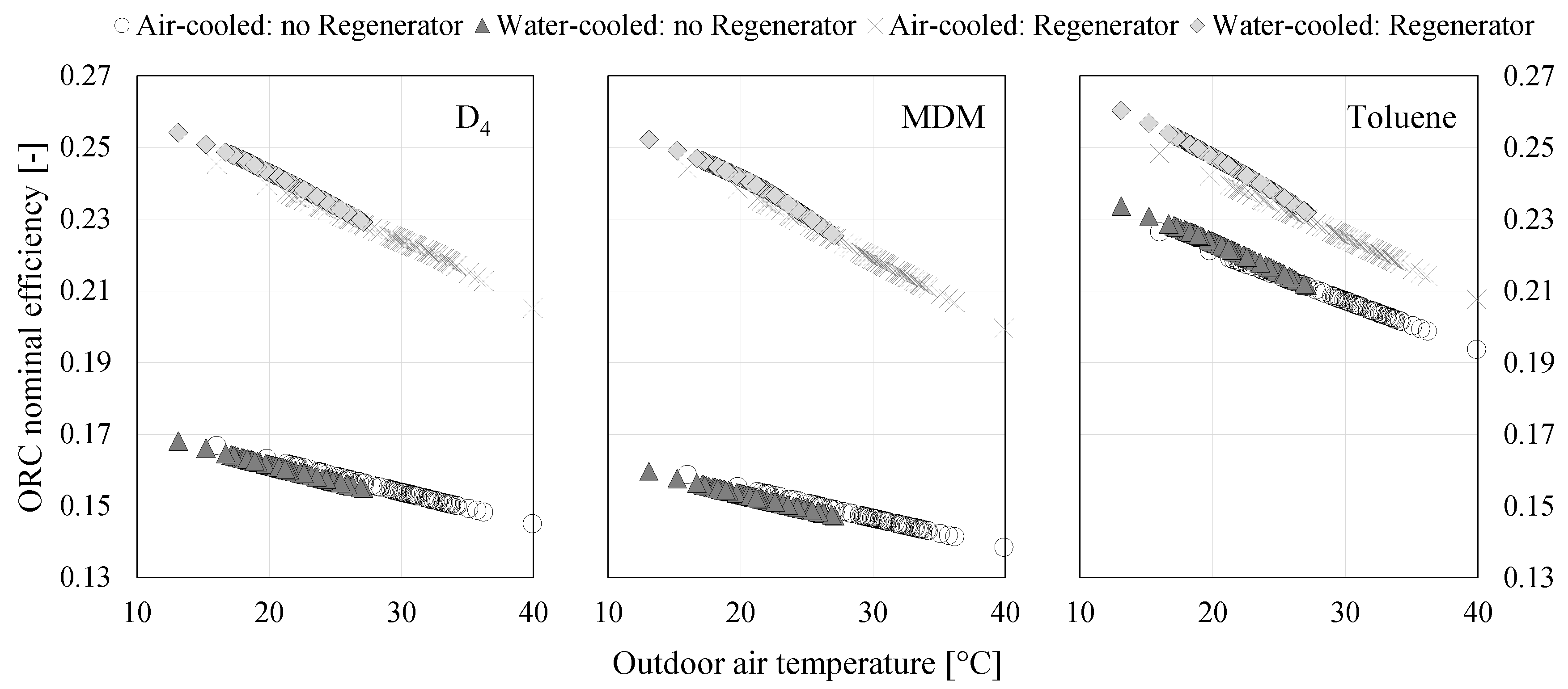
Waste heat input is the same for each location analysed as it is based on a simulated profile developed from monitored data. The most important location-specific parameter affecting ORC nominal efficiency is the condensation pressure, which is directly linked to nominal outdoor air temperature.
Figure 8 shows the almost linear trend of ORC efficiency reduction with nominal outdoor temperature (which affects condensation pressure). The horizontal axes in
Figure 8 represent nominal outdoor air temperature, which is taken as dry-bulb temperature for systems with an air-cooled condenser and wet-bulb temperature for systems with a water-cooled condenser.
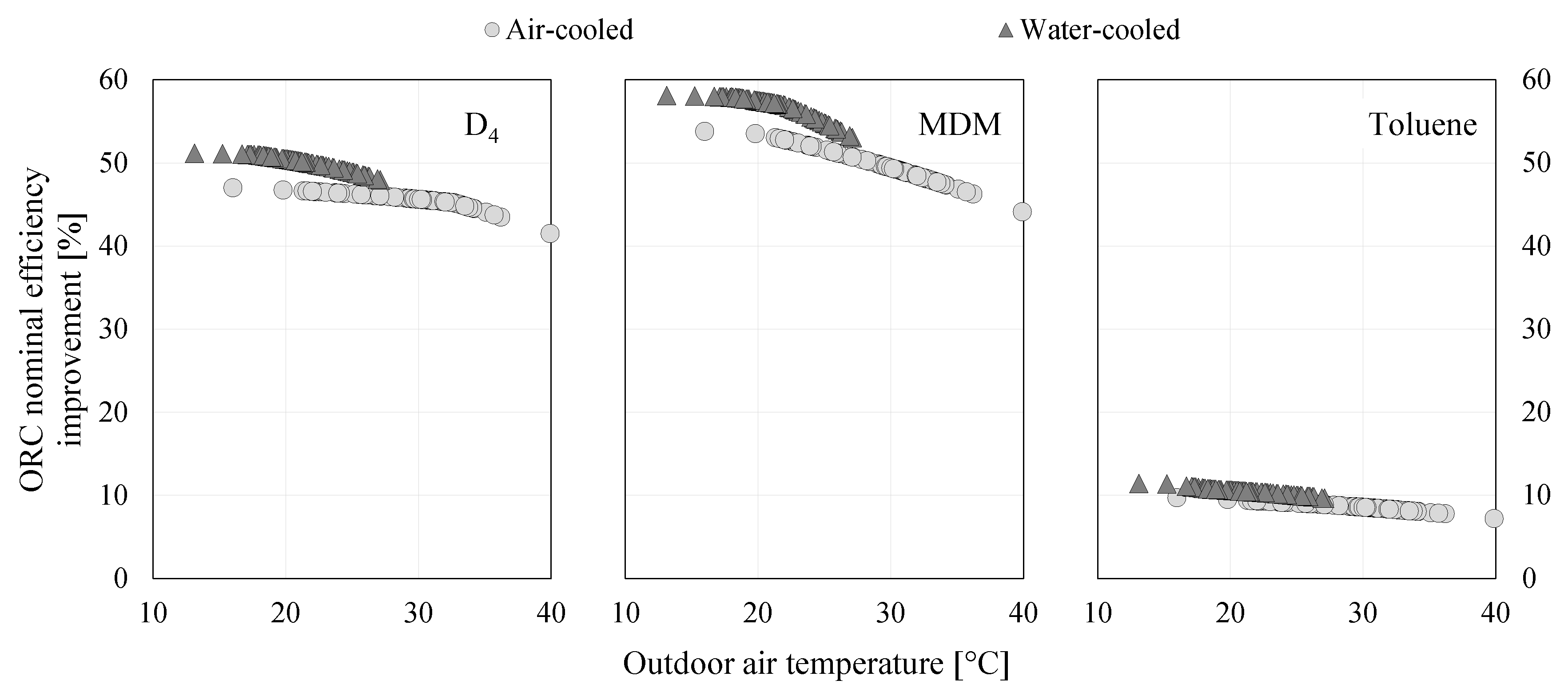
The effect of a regenerator on ORC nominal efficiency is presented in
Figure 9. The degree of improvement reduces with outdoor air temperature. In addition, a regenerator brings greater benefits to systems with a water-cooled condenser than to those with an air-cooled condenser. This is particularly notable in systems with siloxanes as a working fluid, where ORC nominal efficiency can be improved by over 50%. However, the benefit of a regenerator is relatively minor for systems with an aromatic hydrocarbon as a working fluid. In such systems, it is particularly important to carry out a cost-benefit analysis to justify the addition of a regenerator due to the increased complexity and capital cost.
An ORC system with a water-cooled condenser will always have a better nominal efficiency than the same system with an air-cooled condenser, providing we ignore the auxiliary energy consumption, which affects net energy generation. The efficiency difference is larger still for systems equipped with a regenerator at between 3% to over 15% (
Figure 10). Systems with siloxanes as a working fluid and no regenerator show only minor improvements in ORC nominal efficiency though water-cooling, although the improvement increases towards 8% as the difference between nominal outdoor air dry-bulb temperature and wet-bulb temperature increases. The difference between these temperatures is an index of humidity and therefore depends on location. More humid locations have a smaller difference, which suggests the selection of the cheaper and simpler air-cooled condenser despite the slightly better performance that a water-cooled condenser would provide.
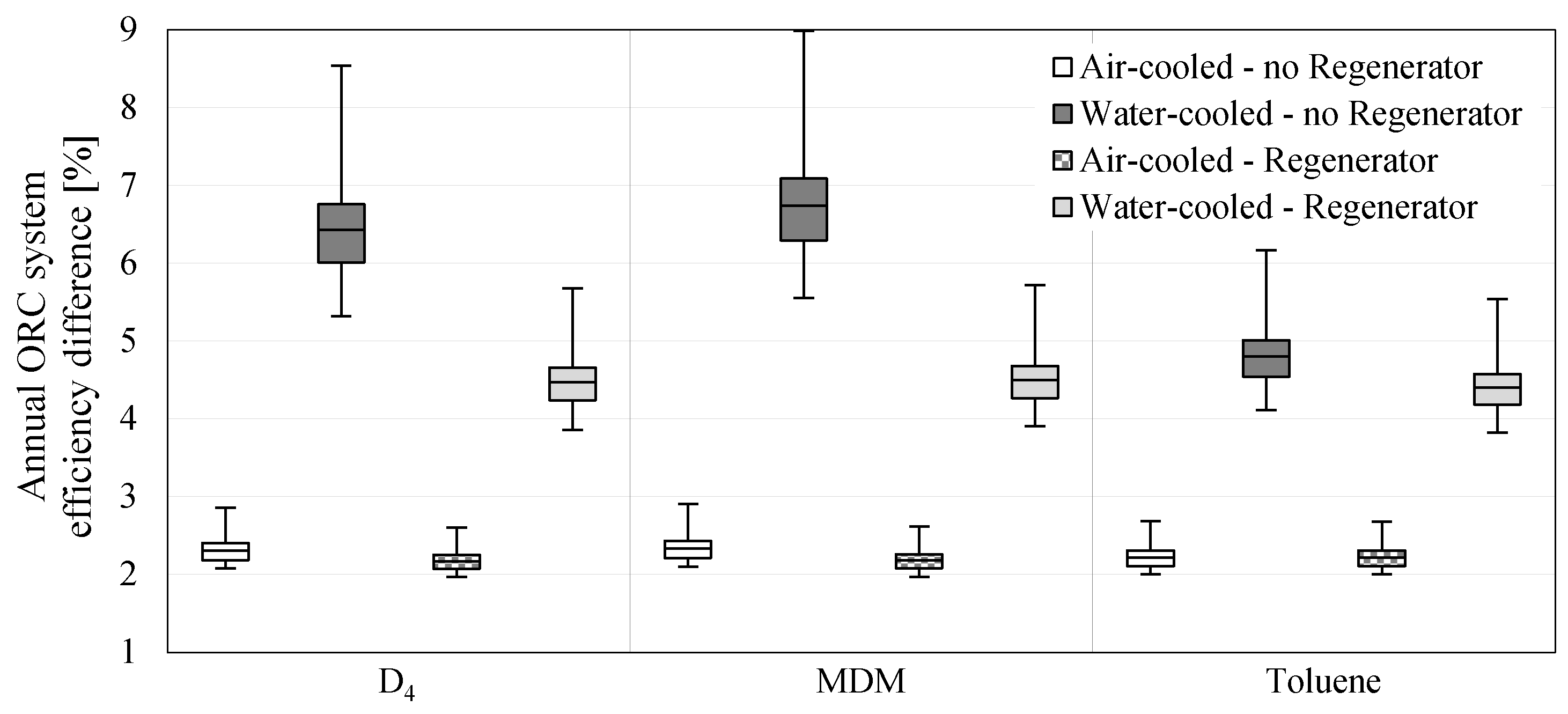
3.2. Annual ORC System Efficiency
The above analysis focused on ORC nominal efficiency and explored the impact of outdoor air conditions, type of condenser and presence/absence of a regenerator on ORC performance at nominal conditions. It did not include the auxiliary energy requirements associated with pump and fan operation, or variations in the waste heat input profile over a typical year. Thermal oil pump electricity consumption is affected by the amount of waste heat available, while the condenser side electricity requirements are affected by the quantity of rejected heat as well as the condition of the outdoor air into which heat is rejected. All of this inevitably has a negative impact on overall system performance, and therefore the net electricity generation.
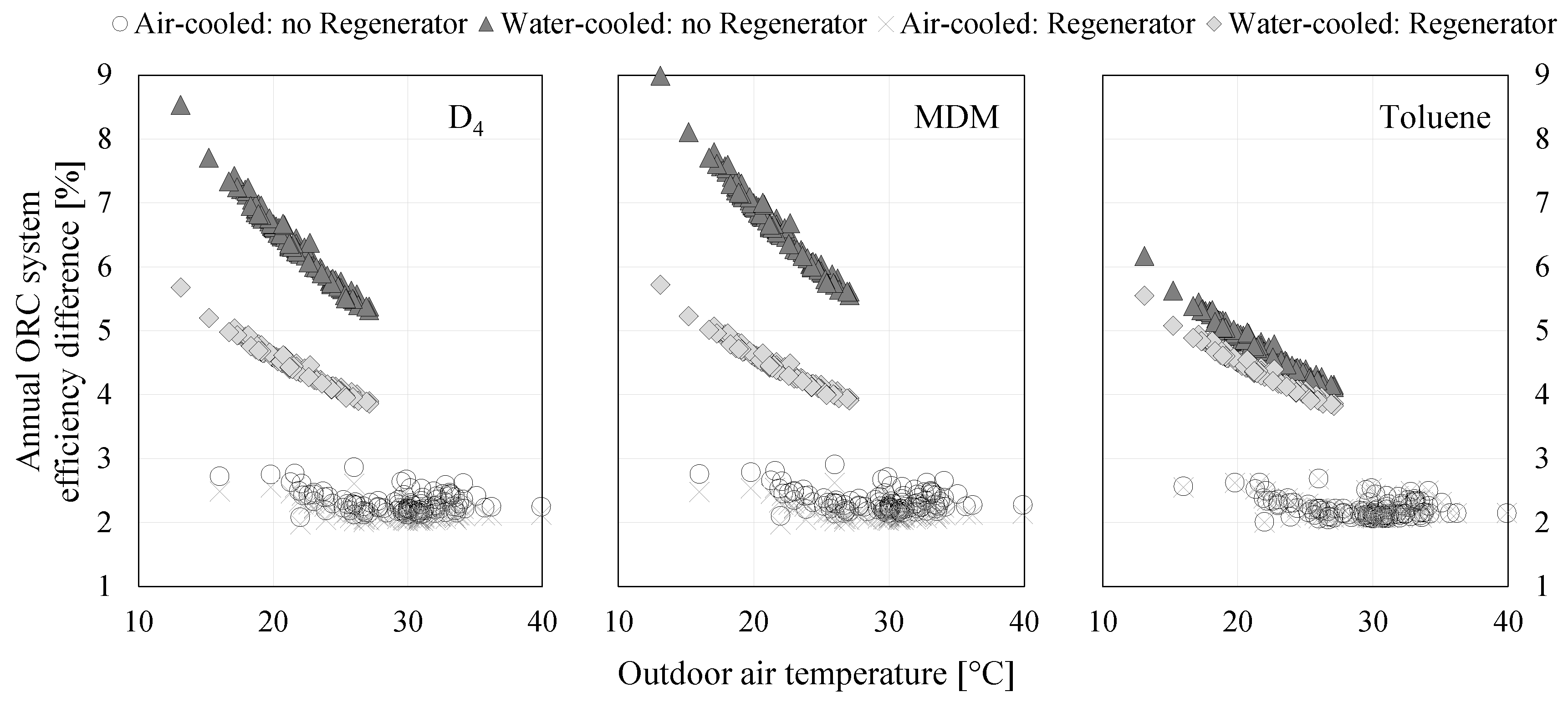
Figure 11 shows the difference between ORC nominal efficiency and annual ORC system efficiency for different system configurations. Systems with an air-cooled condenser show relatively little difference in efficiency (1.9% to 2.9%) irrespective of location or the presence/absence of a regenerator. On the other hand, systems with a water-cooled condenser have a much higher efficiency difference and with a much wider range, depending on location. Systems using siloxanes without a regenerator can have a difference of almost 9% between ORC nominal efficiency and annual ORC system efficiency with an average of 6.4% and 6.7% for D
and MDM, respectively. Systems with a water-cooled condenser and a regenerator have a slightly lower average efficiency difference of 4.5%.
Figure 12 shows the correlation between nominal outdoor air temperature (wet-bulb for water-cooled systems and dry-bulb for air-cooled systems) and the difference between ORC nominal efficiency and annual ORC system efficiency. As already suggested, the efficiency difference for systems with an air-cooled condenser is small irrespective of location. However, water-cooled systems have a strong quadratic relationship between efficiency difference and nominal outdoor air wet-bulb temperature. The efficiency difference increases with decreasing nominal outdoor air wet-bulb temperature. The explanation for this finding lies in the electricity consumption of the cooling tower pump, which is directly related to the cooling tower water flow rate.
A cooling tower is designed to reject heat to the environment and its operation is closely related to the difference between the temperature of the water leaving the tower (cooling tower setpoint, which is kept constant during operation) and the wet-bulb temperature (this difference is known as the “cooling approach”), and the temperature difference between the hot water entering the tower and the cold water leaving it (the so-called “cooling range”).
Cooling range for the fixed cooling approach is related by psychrometrics and cooling tower physics to the outdoor air wet-bulb temperature in such a way that it decreases with decreasing wet-bulb temperature due to the air’s ability to absorb heat in the cooling tower reduces with air wet-bulb temperature. This is important when sizing the cooling tower and the selection of its water pump. If heat is to be rejected in a location with a lower nominal outdoor wet-bulb temperature, then a larger pump will be needed. Calculations of nominal ORC efficiency do not include the pump power, but calculations of annual ORC system efficiency do. A larger pump inevitably leads to a higher annual auxiliary electricity use and therefore a greater difference between these efficiencies.
The significant difference between annual ORC system efficiency and ORC nominal efficiency for water-cooled systems can influence real performance to such a degree that in some situations an air-cooled condenser might actually be preferable. This study has shown that using a water-cooled condenser always results in increased ORC nominal efficiency (
Figure 10); however,
Figure 13 shows that the annual ORC system efficiency might be higher with an air-cooled condenser than with a water-cooled condenser. This is particularly true for systems without a regenerator and with siloxane as a working fluid. In the case of D
, a system with an air-cooled condenser performs better in 66 out of the 106 locations modelled, while for systems that use MDM an air-cooled condenser is best in 88 out of 106 locations. In the other locations, the water-cooled system offers up to a 5% improvement, which is a questionable benefit considering the added complexity of the water-cooled condenser with its extra water pump and water supply requirements. Up to 5% improvement is also obtained in close to 85% of locations when system without regenerator works with aromatic hydrocarbons. To summarise this part of the analysis, if an ORC system is installed in a humid location and it has no regenerator, it is better to couple it with an air-cooled condenser. However, if a regenerator is used then water-cooled systems still perform significantly better although their superiority decreases as the difference between nominal outdoor air dry-bulb and wet-bulb temperature decreases.
3.3. Impact of Exhaust Gas Temperature on Net Electricity Generation
The previous analyses have been undertaken with the reasonable assumption that the waste heat is utilised from a dirty exhaust gas stream. The exhaust gas stream temperature has been kept relatively high to represent safe operation from a corrosion perspective. The total annual waste heat extracted from the exhaust gas when it cooled from over 350 to 180
C is found to be 5.63 GWh. If we cool the exhaust gas more, (as might be permitted in cases where flue gas is less corrosive), there will clearly be more waste heat available; however, this might not necessarily increase the net annual electricity generation. The goal when such a system is installed is usually to maximise net electricity generation, so this part of the study evaluated the impact that exhaust gas leaving temperature (
in
Figure 1) has on the annual ORC system net electricity generation. A trial was carried out using the model, in which the exhaust gas leaving temperature was decreased from 180 to 150
C. This automatically affected the parameters of the thermal oil loop which now operated between 120 and 300
C in order to maintain a minimum temperature difference of 30
C between the exhaust gas stream and the thermal oil. The main advantage of increasing thermal oil temperature range is a decrease in oil pump power consumption in order to maintain the transfer of heat from the exhaust gas.
Decreasing the exhaust gas leaving temperature has a negative impact on both ORC nominal efficiency and annual ORC system efficiency. This is because the ORC operating with a lower evaporation pressure, which is driven by the evaporator pinch () of 10 C. However, this decreased annual ORC system efficiency might not diminish the waste heat recovery potential which rises to 6.32 GWh by decreasing exhaust gas leaving temperature to 150 C. Of course, lower efficiency does not necessarily lead to reduced output if more of the waste heat resource can be recovered and converted to electricity.
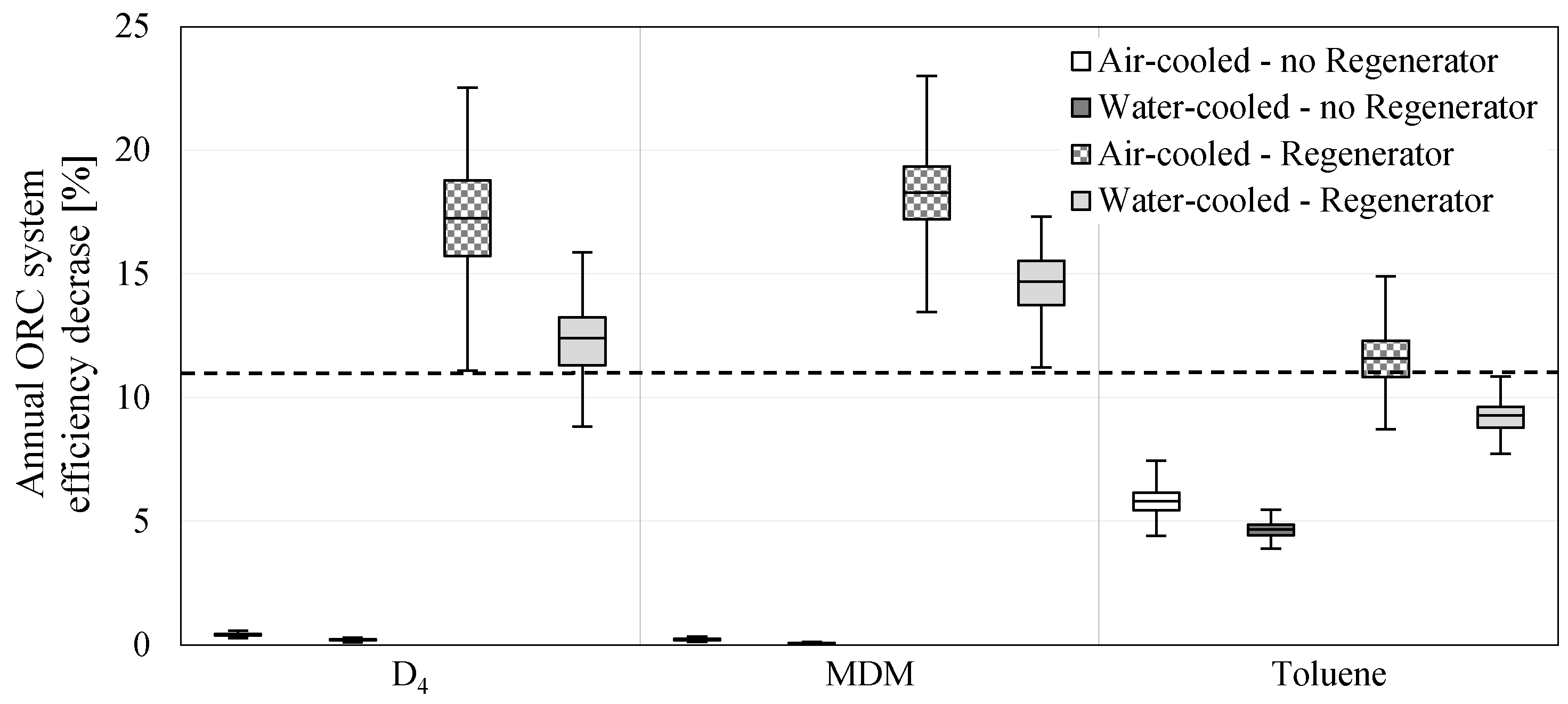
The effect of decreasing the exhaust gas leaving temperature on annual ORC system efficiency is presented in
Figure 14. This effect is negligible in systems using siloxanes and without a regenerator. Systems with Toluene and without a regenerator show a slight drop in performance, although still not enough to annul the increase in waste heat recovery of 12.38%, which leads to enlarged net electricity generation. However, if annual ORC system efficiency drops by 11% or more, as shown by the dashed line in
Figure 14, the increased waste heat recovery is accompanied by reduced net electricity generation. It can be seen that this happens at every one of the 106 locations analysed for systems with a regenerator, air-cooled condenser and siloxanes. Net generation is also reduced in systems with MDM, a regenerator and a water-cooled condenser, irrespective of location. Around three quarter of locations are also not suitable for decreasing the exhaust gas leaving temperature if the ORC system uses D
with a regenerator and is water-cooled or it works with Toluene, a regenerator, and is air-cooled.
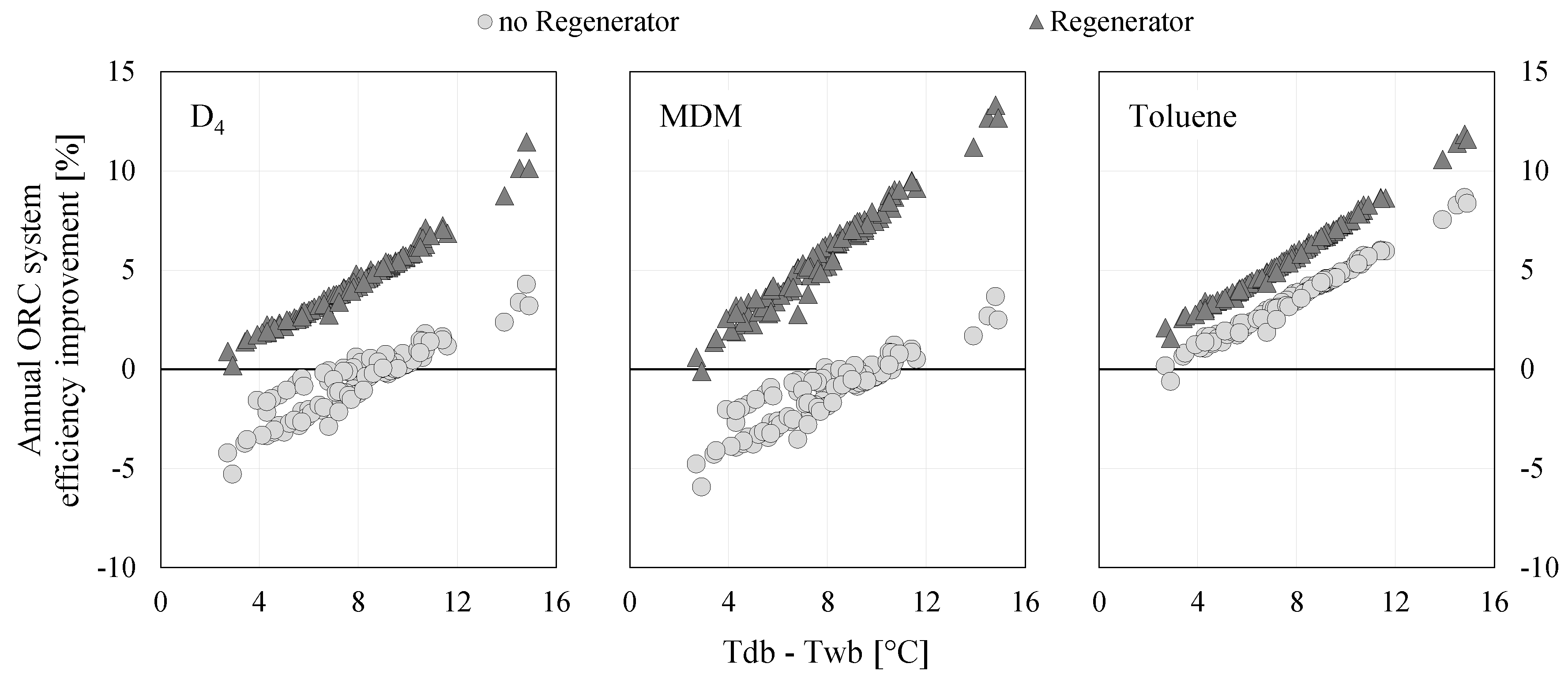
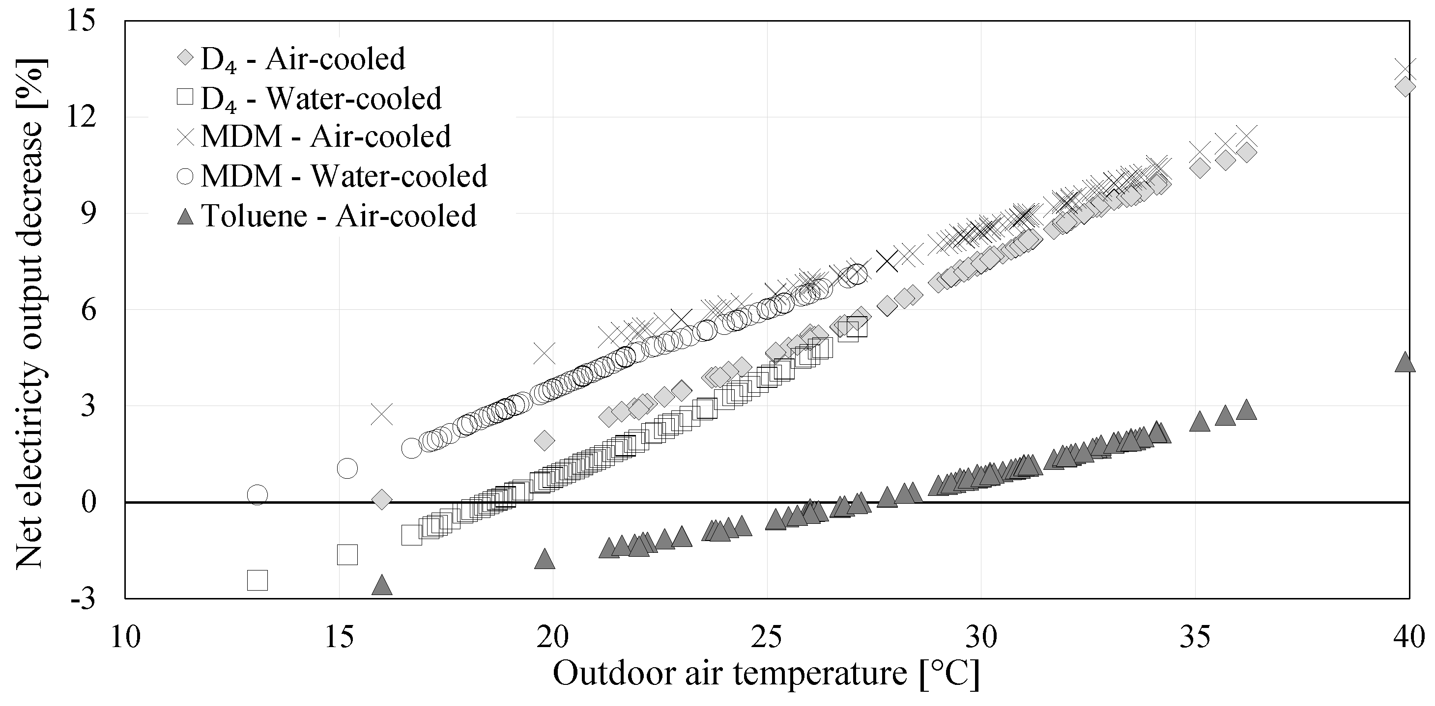
The range of overall ORC efficiency decrease is quite large for systems with a regenerator, which means that the annual ORC system efficiency decrease is location-dependent; thus, the decrease in net electricity generation can be linked to nominal outdoor temperature. This is illustrated in
Figure 15, which shows an almost linear relationship between the decrease in net generation due to decreasing exhaust gas leaving temperature and increase in nominal outdoor air dry/wet bulb temperature. In hot places, such as Seville, a siloxane-based system with a regenerator and an air-cooled condenser can have a drop of up to 14% in electricity generation over the year by decreasing the exhaust gas leaving temperature from 180 to 150
C despite the resulting rise in available waste heat recovery.
4. Conclusions
A power system supplied by waste heat from an iron foundry via an ORC was modelled using published data on the behaviour of a range of working fluids and well-established thermodynamic relationships between the various ORC system components. The model was designed to analyse the effect of adding a regenerator, choosing between an air-cooled or water-cooled condenser and operating the system in a range of European locations. Finally, the modelled ORC system was driven by a waste heat profile that was derived from 15 weeks of real data collected from an Italian foundry.
The results confirmed that choice of location could result in significant differences between ORC nominal efficiency and annual ORC system efficiency, due to the effect of climate on the performance of the condenser and the auxiliary energy requirements of pumps and fans used in both the condenser and the evaporator thermal oil loop. Due to the large number of combinations of system design decisions concerning choices of working fluid, condenser type and whether or not to use a regenerator, the optimal system design to make the best use of available waste heat in a specific location is not at all obvious and may indeed be counter-intuitive. Examples of counter-intuitive results are the findings that increasing the amount of waste heat recovered may actually decrease net annual generation and that the use of a regenerator is not always beneficial.
This study has demonstrated the value of ORC system modelling and of including auxiliary system components and a consideration of climate conditions at the intended location. It has been shown that, for a given waste heat profile, the geographical location of an ORC installation can have a critical impact on the correct choice of system design as well as the cost benefits of using recovered waste heat to generate electricity. Further research is planned to evaluate the accuracy of the model used in this research by comparison with a real ORC installation.


