Article

Cooling Performance Characteristics of the Stack Thermal Management System for Fuel Cell Electric Vehicles under Actual Driving Conditions

1
Thermal Management Research Center, Korea Automotive Technology Institute, 74 Younjung-Ri, Pungse-Myun, Chonan 31214, Korea
2
Research and Development Division, Nano Thermal Fusion Technology Company (NTF TECH), Hadan 840, Saha-gu, Busan 49315, Korea
3
Department of Mechanical Engineering, Dong-A University, Busan 49315, Korea
*
Author to whom correspondence should be addressed.
Energies 2016, 9(5), 320; https://doi.org/10.3390/en9050320
Submission received: 12 February 2016 / Revised: 5 April 2016 / Accepted: 18 April 2016 / Published: 25 April 2016
(This article belongs to the Special Issue Polymer Electrolyte Membrane Fuel Cells 2016)

Abstract

:
The cooling performance of the stack radiator of a fuel cell electric vehicle was evaluated under various actual road driving conditions, such as highway and uphill travel. The thermal stability was then optimized, thereby ensuring stable operation of the stack thermal management system. The coolant inlet temperature of the radiator in the highway mode was lower than that associated with the uphill mode because the corresponding frontal air velocity was higher than obtained in the uphill mode. In both the highway and uphill modes, the coolant temperatures of the radiator, operated under actual road driving conditions, were lower than the allowable limit (80 °C); this is the maximum temperature at which stable operation of the stack thermal management system of the fuel cell electric vehicle could be maintained. Furthermore, under actual road driving conditions in uphill mode, the initial temperature difference (ITD) between the coolant temperature and air temperature of the system was higher than that associated with the highway mode; this higher ITD occurred even though the thermal load of the system in uphill mode was greater than that corresponding to the highway mode. Since the coolant inlet temperature is expected to exceed the allowable limit (80 °C) in uphill mode under higher ambient temperature with air conditioning system operation, the FEM design layout should be modified to improve the heat capacity. In addition, the overall volume of the stack cooling radiator is 52.2% higher than that of the present model and the coolant inlet temperature of the improved radiator is 22.7% lower than that of the present model.

1. Introduction

Owing to limited resources and carbon dioxide (CO2) emissions during combustion, the reduction of fossil fuel consumption is essential for the automotive industry. Concerns about the environmental impact of this consumption and consequent global warming have increased significantly in recent years. As such, extensive global research has focused on realizing zero-emission vehicles, which do not use internal combustion engines, as an alternative to conventional vehicles [1]. The most prominent zero-emission vehicles are battery electric vehicles, range-extended hybrid electric vehicles, and fuel-cell electric vehicles (FCEVs). Their batteries operate on a battery power source only, with a battery only or a hybrid battery system that is charged by an internal combustion engine, and electricity generated by a stack of fuel cells, respectively. All three types of vehicles are considered especially promising, as evidenced by the development undertaken by major automotive companies [2,3,4]. However, lab and on-road tests have revealed various engineering shortcomings of FCEVs that must be overcome in order to achieve similar performance to that of internal combustion engine vehicles. These shortcomings include the system efficiency, stack performance, thermal-management technology, as well as compatibility among other components under high-voltage conditions [5]. Several papers have addressed issues associated with the development and commercialization of FCEVs. The effective discharge of heat generated from the stack constitutes one of the main technical challenges for the FCEV. In fact, from the thermal management viewpoints, since fuel cell electric vehicles have favorable working temperature ranges from 60 °C to 80 °C, liquid cooling is considered to be the optimum system to achieve allowable coolant temperatures under 80 °C [6,7,8]. Islam et al. introduced fuel cell cooling systems by size of fuel cells and reviewed the potential of applying nanofluids in cooling systems for fuel cells used in FCEVs. As a result, they reported that coolant using nanofluid has a high heat rejection effect, therefore the size of the radiator for the fuel cells can be reduced relatively [6]. Zhang and Kandlikar reviewed the various cooling techniques—cooling with heat spreaders, cooling with separate air flow, cooling with liquid, and cooling with phase change—for fuel cell stacks on the basis of technical research publications and patents [7]. Kandlikar and Lu reviewed the fundamental heat transfer mechanisms at the component level of a fuel cell. The current status of PEMFC cooling technology was also reviewed and research needs were identified. They explained the importance of the intimate relation between the fuel cell thermal and water transport mechanisms which has an effect on the fuel cell performance [8]. Furthermore, Shabani et al. reported that the ratio of cooling load and power generation increased with the power generation and the operating temperature increment [9]. In particular, the corresponding initial temperature difference (ITD) between the coolant and the cooling air of the stack radiator is almost 50% lower than that of an ICE due to the different coolant operating conditions. Therefore, the cooling capacity of the stack radiator, which is approximately proportional to the ITD, must be twice as high as that of a conventional radiator [10]. A few articles have focused on the stack thermal management system of FCEVS. For example, Kim et al. investigated the heating-performance enhancement of a CO2 heat-pump system that recovered the stack exhaust thermal energy in FCEVs. They reported on the heat-pump system that heats the passenger room, by using the waste heat from the stack [11]. Lee et al. evaluated the cooling performance of an electric air-conditioning (A/C) system, for use in an FCEV [12]; this A/C system used R744 (Carbon dioxide) as coolant. They suggested a modified electrical A/C system (using R744) for the FCEV and analyzed the cooling performance of this modified system under various operating conditions. In addition, they reported that the cooling COP of the A/C system was, on average, 24.3% higher than that of the system that uses R-134a. Kim et al. evaluated the performance of a stack cooling system in FCEVs that use a CO2 A/C system [13]. In addition, studies conducted on the stack systems of FCEVs have revealed that various approaches are required to realize effective cooling of the stack management system. These approaches outnumber those required for an ICE radiator; for example, more frontal area, an optimum layout, and assembling must be considered for FCEVs. Hager and Schickmair found that, for optimum frontal area, the stack radiator must be 70% larger than that of an ICE radiator [14]. The components and layout of the cooling system for FCEVs were described by Ngy-Srun [15]. They concluded that the extended heat transfer region and low pressure drop, via the radiator grille, should be considered in order to obtain an optimum design that improves the cooling capacity of the stack system. However, the cooling systems of the stack thermal management of FCEVs have barely been studied. Therefore, to address the aforementioned issues, the cooling performance of the stack thermal management system of an FCEV is evaluated in this work. Kim et al. previously evaluated the performance of a supplementary stack cooling system for FCEVs that use a CO2 A/C unit [16]. As such, the objective of this work is to evaluate, via experiments, the cooling performance of the stack thermal management system of FCEVs under various actual driving conditions and investigate how to improve cooling performance within the layout limitations of the vehicle. The thermal stability required for stable operation of the FCEV and suitability of the experimentally determined stack-cooling capacity of the system under actual driving conditions, were analytically evaluated via one-dimensional modeling which was built as an installed cooling module in the tested vehicle and used data obtained from operation of the FCEV under various actual road driving conditions. The simulations were performed under difficult conditions due to environmental factors with respect to cooling system and the way to improve cooling performance with minimum alterations was analyzed.

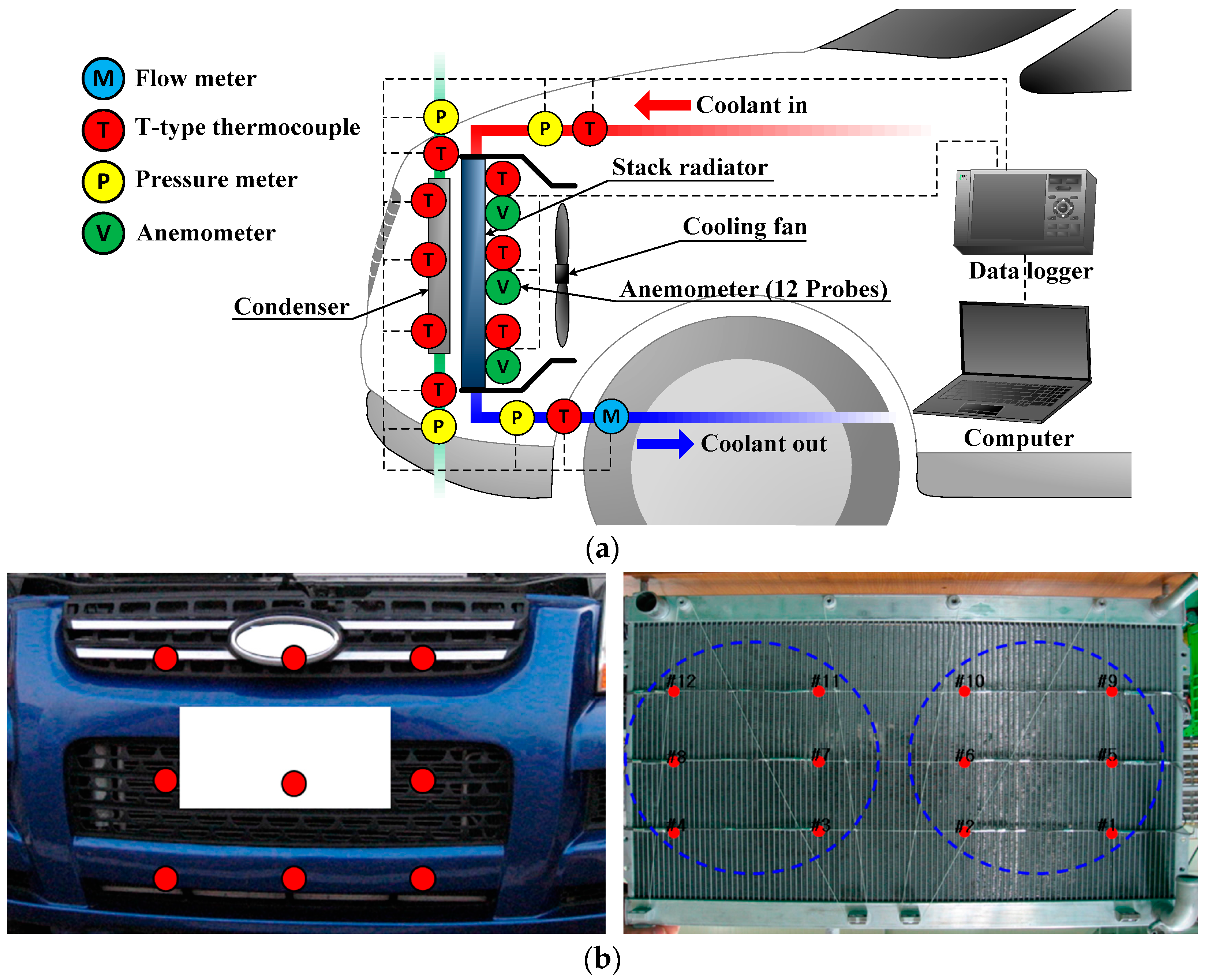
2. Experimental Method

2.1. Experimental Setup

Cooling performance characteristics of the stack thermal management system of the tested fuel cell electric vehicle were investigated to understand the variations of cooling load under various driving conditions. Also, the accumulated results obtained by experiments were used to verify an analytical model for simulating the cooling performances of the considered system under virtual driving conditions. An experimental apparatus was installed in order to evaluate the cooling performance of the stack thermal management system of the FCEV. The frontal air properties, such as temperature and velocity, on the stack radiator was measured during actual road driving of the vehicle. Figure 1 shows a schematic of the apparatus that is used to estimate the cooling capacity of the thermal management system under actual road driving conditions. It indicates the measurement locations for the temperature, pressure, and volume flow rate of the coolant-side and the temperature of the air-side, and the positions of the anemometers (12 probes) used to calculate the air flow rate. The radiator inlet and outlet temperatures were measured, with an accuracy of ±0.1 °C, by using thermocouples. To calculate the pressure difference of the coolant-side of the radiator, pressure sensors with an accuracy of ±0.1% were installed at the inlet and outlet of coolant-side of the radiator as shown in Figure 1a. The mass flow rate of the coolant was measured by installing a coolant volume flow meter at the front of the stack radiator. The volume flow rate of the turbine-type flow meter was measured to an accuracy of ±0.25%.
Furthermore, a portable data logger (Gartner Instruments GmbH, Schruns, Austria) was used to store the data. The frontal air velocity of the stack radiator, was measured by installing an anemometer on the cooling module that consists of the radiator and the condenser. Figure 1b shows a photograph of the measurement locations on the stack radiator of the anemometer, which was mounted to the rear-face of the core, between the radiator and fan shroud. Figure 1c shows the air velocity of the stack radiator with measuring locations as a function of the vehicle driving velocity. This result indicates that the layout of the radiator, including the radiator grille and the bumper hole of the radiator, has a significant effect on the air inlet of the radiator. Figure 1d shows the frontal air velocity of the stack radiator as a function of the vehicle driving velocity, with and without operation of the A/C system. In fact, the layout plays an important role in realizing the optimum heat transfer rate of the stack radiator. This heat transfer rate is approximately two times higher than that of the conventional internal combustion engine, owing to the lower temperature difference between the coolant inlet and air inlet of the stack radiator [17]. A frontal air velocity of 2–3 m/s is therefore estimated for the stack radiator, with the fan in the idle condition. Frontal air velocities of 5 m/s and 6 m/s without and with operation of the fan, respectively, are estimated in the case of the high vehicle driving velocity. The cooling performance of the stack thermal management system was evaluated by determining the volume flow rate of the coolant side, inlet and outlet temperatures, and the frontal flow rates of the air-side of the radiator. Table 1 shows the specifications of the stack cooling system of the FCEV. The FCEV investigated in this work had a stack capacity of 80 kW. The stack radiator has a 690 mm (wide) × 435 mm (height) × 26 mm (depth) multi-flow-type core, and a heat-rejection rate of 36 kW at a coolant flow rate of 100 L/min. Furthermore, the motor power and diameter of the fan of the radiator are 120 W and 320 mm, respectively.
The heat-rejection rate of the condenser, which has a 590 mm (width) × 360 mm (height) × 16 mm (depth) multi-flow-type core, is 5.2 kW at an air velocity of 2 m/s. An electric-driven pump was used to circulate the coolant of the stack cooling system at 5000 rpm and 202.6 kPa, with a volume flow rate of 200 L/min. Table 2 shows the test parameters used in this study. During the experiments, the driving velocity of the vehicle was set to 100–120 km/h, in order to evaluate the highway driving condition at higher stack-cooling loads; the uphill driving condition at both high stack-cooling load and low cooling air-flow rate (resulting from low velocity), is evaluated at velocities of 30–50 km/h. The heat-transfer rate at the coolant side of the stack thermal management system was determined from the measured data, by using the temperature difference method [18]. This rate is given as follows:
Q ˙ c o o l a n t = m ˙ c o o l a n t C p , c o o l a n t Δ T c o o l a n t

2.2. Analytical Method

The cooling performance of the stack thermal management system operated under actual driving conditions was investigated, by using the analytical method embedded within the commercial automotive thermal management software KULI; core components of the tested stack cooling system were aligned according to the cooling air-flow direction [19,20]. Figure 2 shows the components used in the one-dimensional modeling of the stack cooling system of the FCEV under various driving and actual road conditions. The considered simulation model was set up based on the cooling system and layout of the considered vehicle. As Figure 2 shows, the stack room resistance is the same as the air-flow resistance at all locations, except for the front end module (FEM). The built-in-resistance, including that of the radiator grille and the bumper hole, is considered an obstacle to the air flow for cooling. Values of the CPs (Characteristic parameters) of the air inlet and outlet were used to reflect vehicular speeds and air properties under simulation conditions. The aforementioned analytical method is used to investigate the cooling performance characteristics of the stack thermal management system of the FCEV under various driving conditions and A/C system operation. Driving conditions referred to as highway mode and uphill mode, which correspond to high cooling load with sufficient and insufficient air-flow cooling, respectively, were investigated. The temperature of the cooling air of the stack radiator increases, owing to the heat rejection from the condenser. As such, the performance of the stack cooling system was evaluated by varying the operating conditions of the A/C system. Table 3 shows the simulation parameters used in this study. From the viewpoint of suitability for the cooling system, the coolant inlet temperature of the stack radiator must be maintained at values lower than 80 °C. This is the maximum temperature at which stable and efficient operation of the FCEV can be maintained, although the engine radiator can perform reliably at temperatures of up to 100 °C [21].

3. Results and Discussion

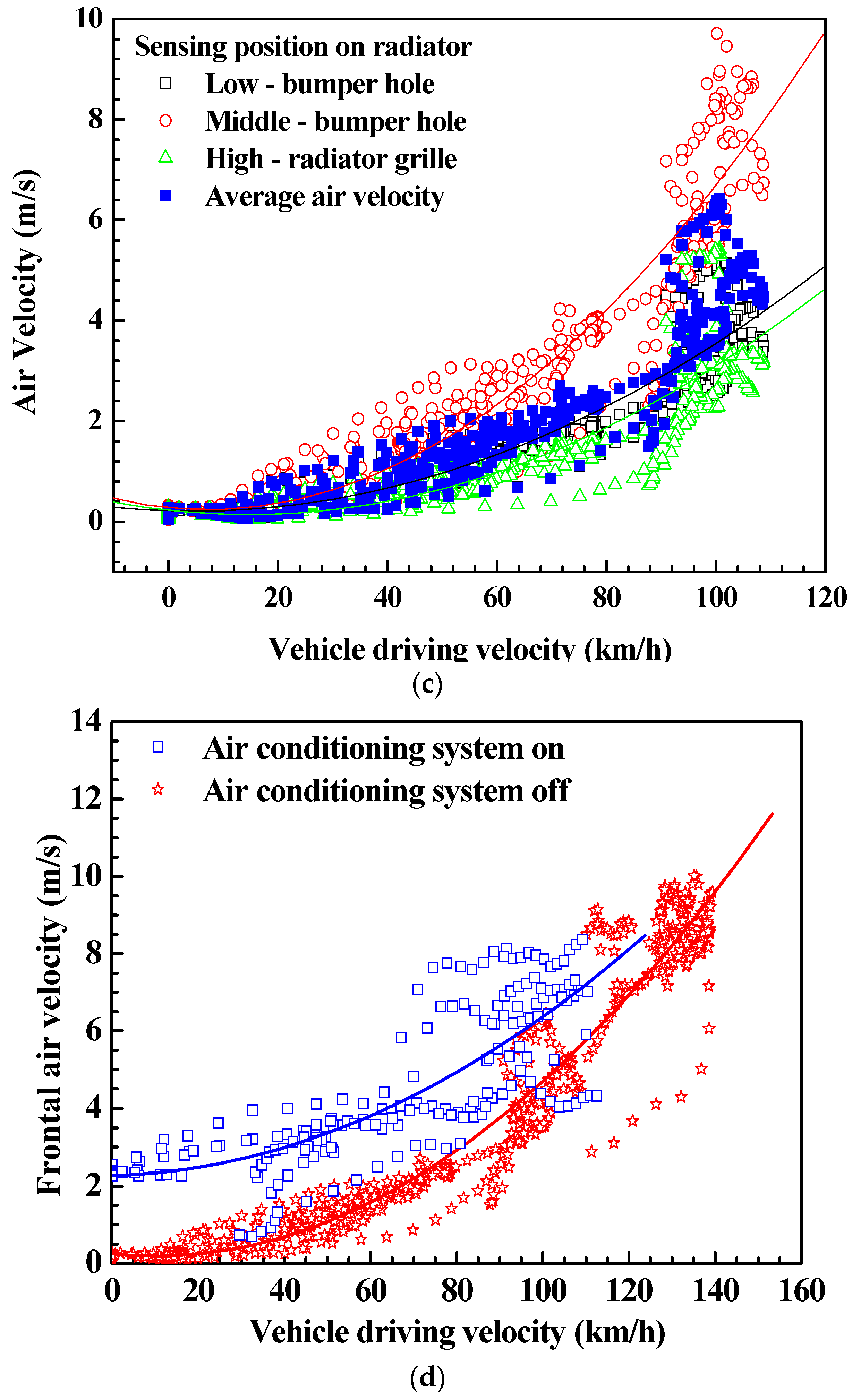
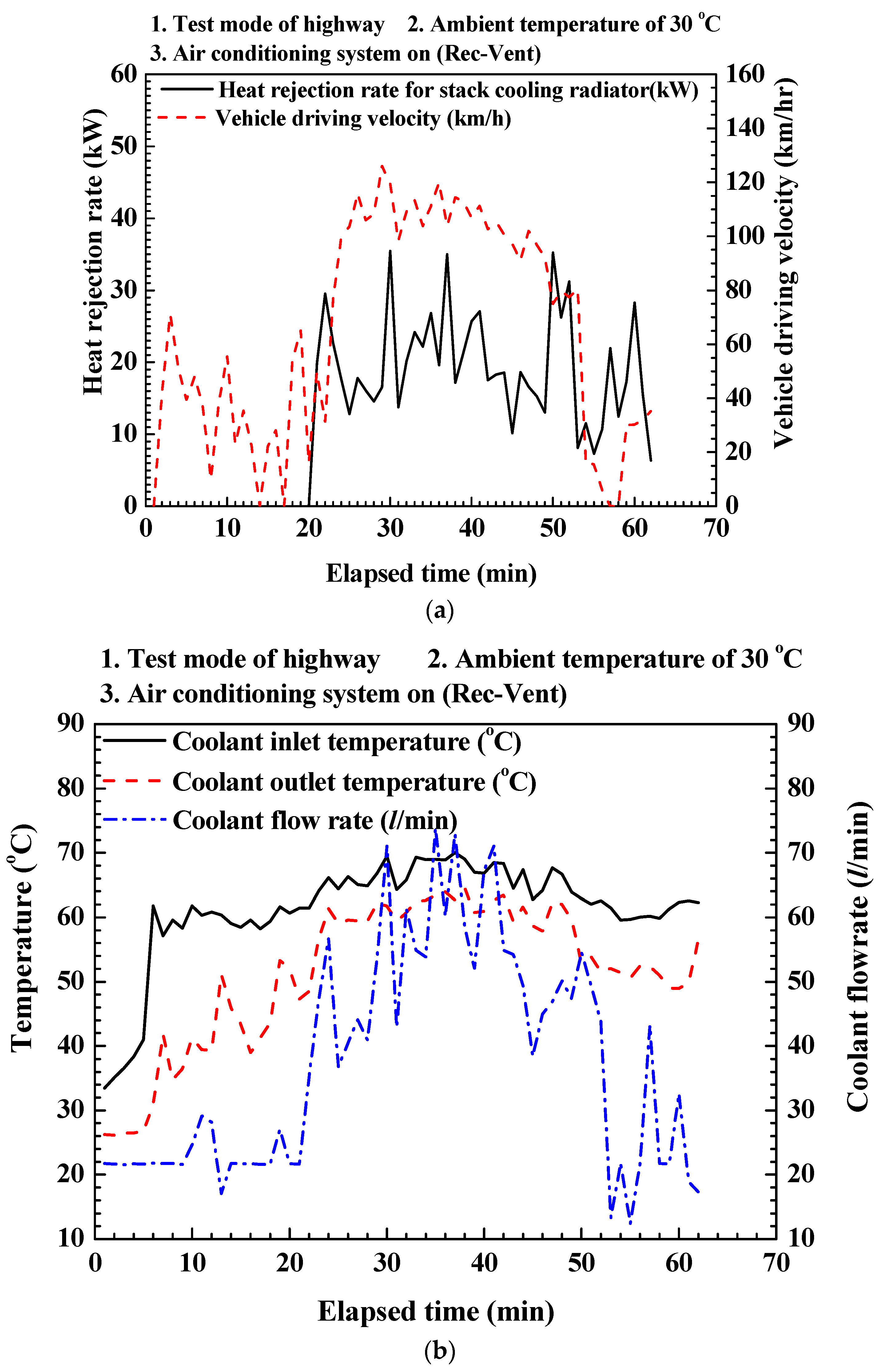
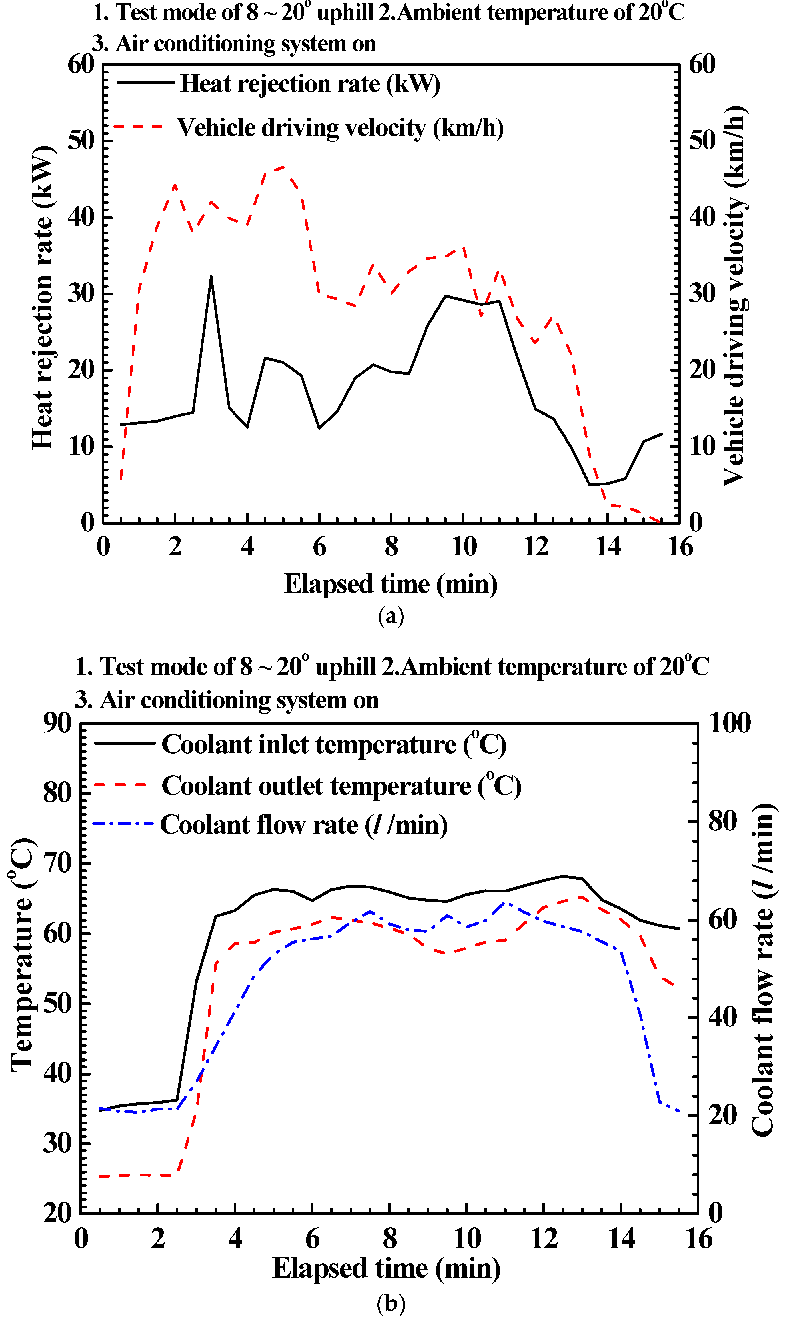
3.1. Cooling Performance of the Stack Thermal Management System under Actual Driving Conditions

Figure 3 shows the cooling performance of the stack thermal management system of the fuel-cell electric vehicle under highway-driving road conditions. The coolant temperature and volume flow rate of the stack radiator used in the system were determined at an average ambient temperature and vehicle velocity of 30 °C and 100 km/h, respectively. The maximum driving velocity during testing was 120 km/h, and the A/C system was turned on. These conditions were used to evaluate actual driving conditions under high ambient temperature and high thermal load of the radiator, owing to the condenser. The low ITD between the temperatures of the coolant and the air was also considered in this evaluation; the ITD is essential for exchanging the heat of the radiator at the required heat capacity of the system. As shown in Figure 3, at low flow rate of the coolant and initial driving conditions, the temperature gap through the stack radiator was distinctly higher than that of high flow rate of the coolant, which seemed to indicate that the coolant flowed through a bypass line because the controlled setting temperature for cooling the fuel-cell stack was not reached. However, at high coolant flow rate and inlet temperature, the temperatures differ by only 5–7 °C, indicative of the high power generation that leads to acceleration. The coolant pump of the radiator was operated at a maximum flow rate of 70 L/min, under stable and fast driving conditions. In other words, the coolant inlet temperature of the radiator was maintained at temperatures lower than ~75 °C for the stable operation of the stack thermal management system; the coolant supply pump was also controlled. Fuel-cell stacks for PEMFC are efficiently operated at temperatures ranging from 70–80 °C [22]. The coolant temperature of the radiator was maintained at temperatures below the allowable limit of 80 °C, thereby ensuring stable operation of the stack thermal management system of the fuel-cell electric vehicle. Figure 3 shows the cooling performances of this system under highway-driving road conditions. Under these conditions, the heat-rejection rate of the radiator is (on average) 20.0 kW, which remains relatively steady owing to the sufficiently high air-flow rate and the constant heat load. The maximum heat-rejection rate at the maximum temperature difference (7.3 °C) between the stack coolant inlet and outlet, was 35.0 kW. As Figure 3b shows, at the initial stages of driving, coolant temperature gap through the stack radiator from the inlet to the outlet measured somewhat high by 20 °C with a low coolant flow rate of 20.0 L/min. These results were caused by the bypassed coolant flow path due to lower temperature of controlled setting condition to the stack radiator. Hence, installed temperature sensor at the outlet of stack radiator had the constant value because of clogged flow line, while that at the inlet was variable. In addition, the present stack thermal management system was operated at a maximum temperature of 80 °C, under highway-driving road conditions with an A/C system on.
Figure 4 shows the cooling performance of the thermal management system under uphill road conditions. The coolant temperature and volume flow rate of the radiator of the thermal management system were determined. These tests were performed at inclination angles of 8°–20° and an average ambient temperature and vehicular speed of 20 °C and 40 km/h, respectively, with the A/C system on. The system was operated at 600–1100 m above sea level in order to maintain this temperature and uphill driving conditions during the test. The thermal load of the system under uphill road conditions is expected to be greater than that associated with highway driving road conditions. The ITD between the coolant and the air was higher under uphill road conditions than under highway driving road conditions. The inlet coolant temperature of the radiator, as previously stated, was lower than the maximum operating temperature (80 °C) at which stable operation of the stack thermal management system is maintained. As a result, the coolant pump of the stack radiator yielded a maximum volume flow rate of ~60 L/min; furthermore, the maximum heat-rejection rate, was 30.0 kW at the maximum temperature difference (7.6 °C) between the stack coolant inlet and outlet.

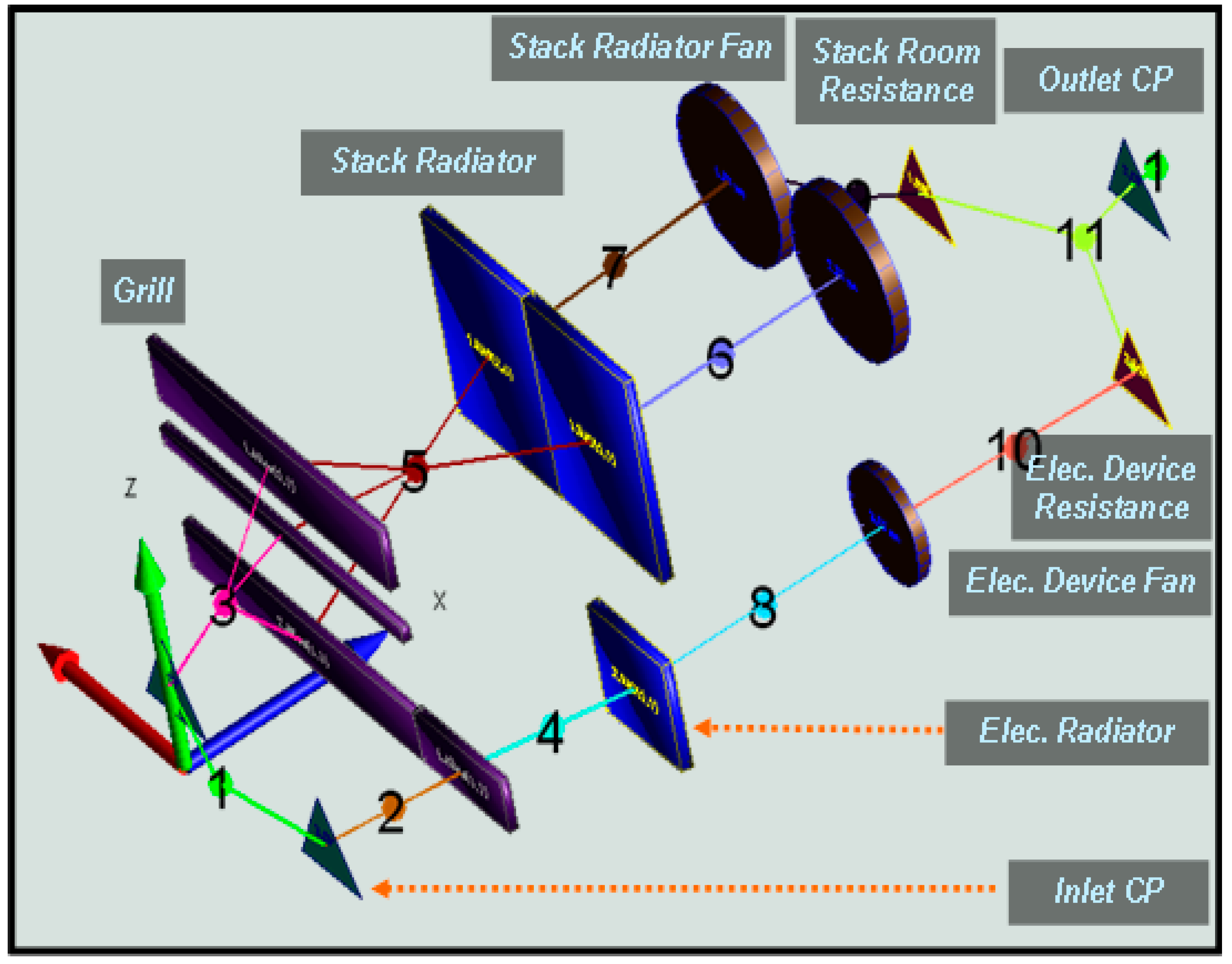
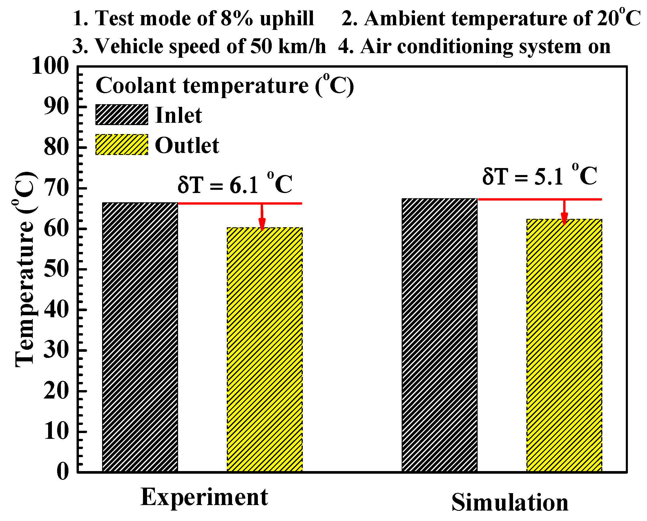
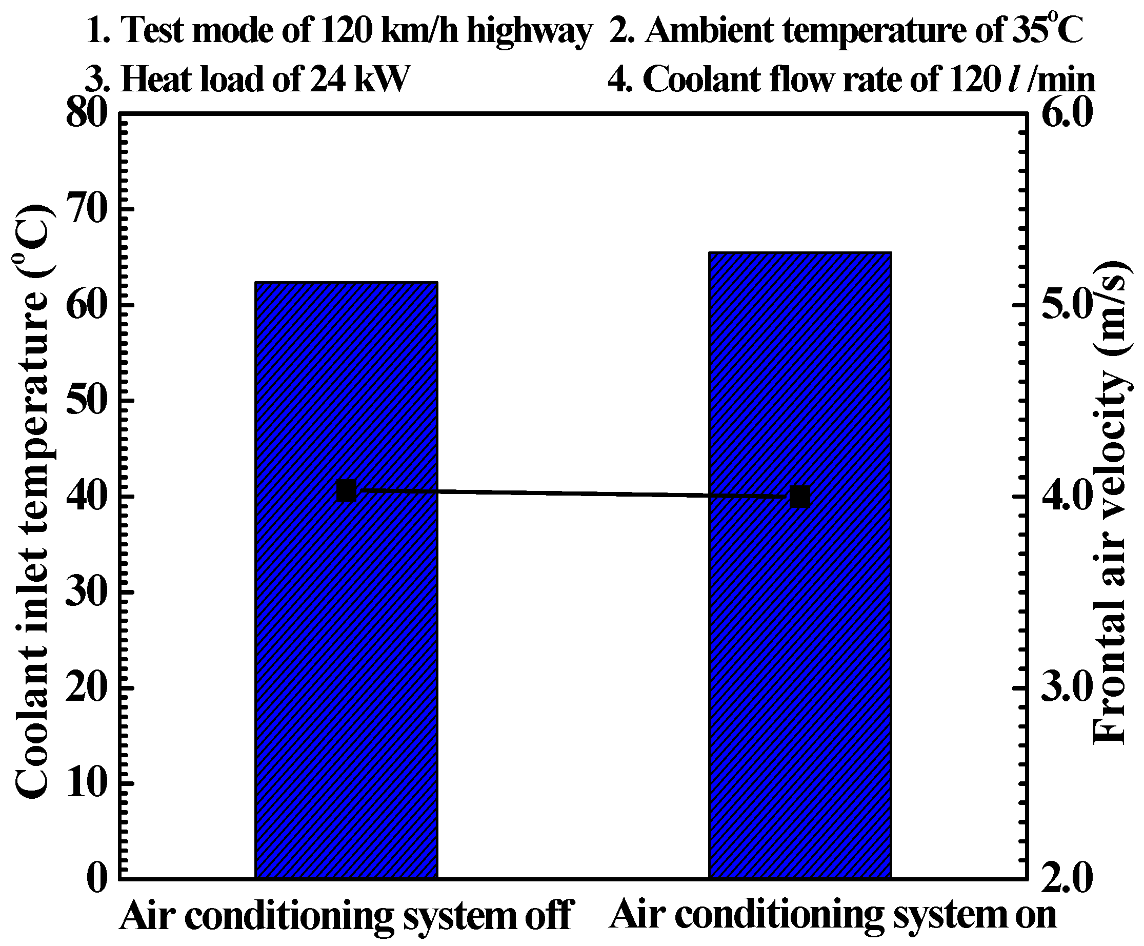
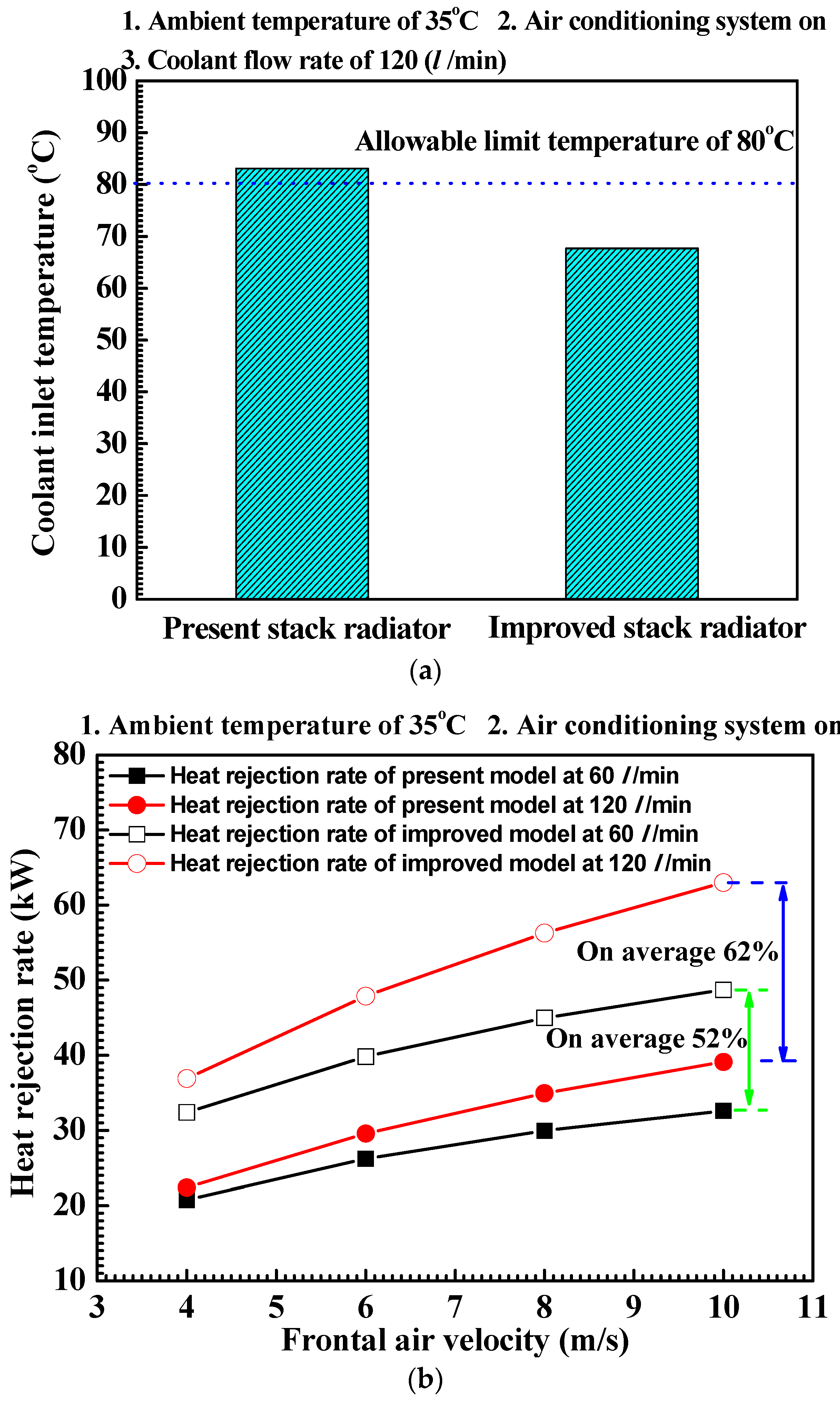
3.2. Cooling Performance Simulations of the Stack Thermal Management System under Actual Driving Condition

The cooling performance of the stack thermal management system of the fuel-cell electric vehicle was analyzed by using KULI, a commercial simulation program; the thermal stability required for stable operation of the stack cooling system of the vehicle was analytically determined. Based on the results shown in Figure 3 and Figure 4, the cooling performance characteristics of this system were described; the cooling system exhibited a stable performance. When the A/C system of the vehicle is operated, the thermal load of the stack radiator increases (in general) with decreasing ITD, owing to the additional heat released from the condenser. The stack radiator and the condenser associated with the stack thermal management system and the A/C system, respectively, were designed for the front end module (FEM) of the vehicle. Therefore, based on this layout, the increased thermal load from the condenser should be taken into consideration. The accuracy of the simulation analysis was determined by comparing the simulation data obtained from KULI with the data obtained from actual road-driving tests. The performance of the stack radiator (of the stack thermal management system), as determined from experimental and simulation data, is shown in Figure 5. The performance was determined with the A/C system on, under ambient temperature of 20 °C, vehicle driving speed of 50 km/h, and uphill mode of 8.0°. Under these conditions, the heat load of the fuel-cell stack for the vehicle and the heat-rejection rate from the condenser are 27.0 kW and 5.2 kW, respectively. Temperature differences of 6.1 °C and 5.1 °C, between the inlet and outlet temperature of the radiator, were determined from the experimental and simulation data, respectively. The predicted inlet temperature differed by only 1.5% from the experimentally determined value. Figure 6 shows the cooling performance of the stack thermal management system, with and without operation of the A/C system, under highway-driving conditions. The coolant inlet temperature and the frontal air of the stack radiator of the system were determined; tests were performed at an ambient temperature of 35 °C, and a vehicle driving velocity, coolant volume flow rate, and heat load of 120 km/h, 120 L/min, and 27.0 kW, respectively, of the fuel-cell stack. Owing to the heat gain from the condenser, the coolant inlet temperature of the radiator was 3.1 °C higher than that obtained when the A/C system was off. The coolant inlet temperature was, however, lower than the maximum temperature (80 °C) at which stable operation of the stack thermal management system is maintained. This resulted from the sufficiently high cooling capacity, and correspondingly high air-flow rate, which occur at high vehicle driving velocity. Figure 7 shows the cooling performance of the stack thermal management system under highway mode and uphill mode driving conditions. The cooling performance of the stack radiator of the system was determined at an ambient temperature of 35 °C, a coolant volume flow rate of 120 L/min, and heat loads of 27.0 kW and 24.0 kW, of the fuel-cell stack. Furthermore, an inclination angle of 0° and a vehicle driving velocity of 120 km/h were considered for the highway mode; values of 8.0° and 50 km/h were considered for the uphill mode. The coolant inlet temperature of the radiator under highway mode was 13.7 °C lower than that obtained under uphill mode. This resulted from the higher (by 58.7%) air-flow rate associated with the higher vehicular speed under highway mode, compared to that associated with the uphill mode; a higher air-flow rate occurs in spite of the 12.5% higher heat load.
Consider the uphill mode, where the radiator operates under a heat load of 24.0 kW and at an ambient temperature of 35 °C, with the A/C system on. In this case, the coolant inlet temperature would exceed the allowable limit (80 °C) for stable operation of the stack thermal management system. This results from the low air-flow rate, low cooling capacity, and low ITD between the cooling air and the coolant, which all stem from low vehicle driving velocity, with the A/C system on [23]. Based on the results shown in Figure 7, the design of the improved stack radiator should take the design layout of the FEM of the fuel-cell electric vehicle into consideration; this improved radiator enhances the cooling performance of the stack thermal management system.
The FEM design layout was taken into consideration, in order to improve the cooling performance of the stack thermal management system; tests were performed under an ambient temperature of 35 °C, and a coolant volume flow rate, heat load, and inclination angle of 120 L/min, 24.0 kW, and 8.0°, respectively. The volume of the 693 mm (width) × 451 mm (height) × 38 mm (depth) improved stack radiator is 52.2% higher than that of the present 690 mm (width) × 435 mm (height) × 26 mm (depth) radiator. Figure 8 shows the coolant inlet temperatures of the present and improved radiators. Owing to its higher heat capacity, the coolant inlet temperature of the improved radiator is 22.7% lower than that of the present model. This improved stack radiator operates at reasonable temperature levels that ensure stable operation of the stack thermal management system. Figure 8b shows the heat-rejection rate of the system consisting of the present and improved stack radiator models, at coolant flow rates of 60 L/min and 120 L/min. At these flow rates, the heat-rejection rates of the system equipped with the improved radiator were 52% and 62% higher, respectively, than those with the present stack radiator. In addition, compared to the current radiator, the improved stack radiator remained stable for longer durations under more severe conditions; these conditions include extremely high heat load, and hence greater power generation, with an A/C system on.

4. Conclusions

This study evaluated the cooling performance and analyzed the thermal stability of a stack thermal management system of a FCEV, under various experimental conditions (including actual road driving conditions). An experimental apparatus for actual road driving tests was constructed in order to evaluate the cooling performance of the system under different driving conditions. The coolant temperatures of the stack radiator, subjected to highway and uphill travel modes during actual road driving conditions, were maintained at values below the allowable limit temperature of 80 °C. In this way, stable operation of the stack thermal management system of the FCEV was ensured. In addition, under uphill mode and actual road driving conditions, the ITD between the coolant inlet and air inlet of the system was higher than that associated with highway mode; this higher IDT occurred in spite of the greater thermal load of the system under uphill mode, compared to that occurring under highway mode. The cooling performance analysis of the stack thermal management system of the FCEV was also investigated by using the commercial simulation program, KULI. Furthermore, the thermal stability required for stable operation of the stack cooling system was analytically evaluated. The predicted coolant inlet temperature of the stack radiator differed by only 1.5% from the experimentally determined value. When the A/C system was turned on, the coolant inlet temperature of the radiator was 3.1 °C higher than that obtained when the system was turned off; this higher value is attributed to the heat gain from the condenser. The coolant inlet temperature remained below the allowable limit (80 °C) at which stable operation of the stack thermal management system is maintained. This results from the sufficiently high cooling capacity, and correspondingly high air-flow rate, that occur at high vehicular driving velocity. In highway mode, the inlet temperature was 13.7 °C lower than that associated with uphill mode. This is attributed to the higher (by 58.7%) air-flow rate that occurs at the higher vehicular speed associated with highway mode, compared to that associated with uphill mode; the higher air-flow rate occurs in spite of a 12.5%-higher heat load. The coolant inlet temperature may exceed the desired limit in the case of uphill mode at high ambient temperature, with the A/C system turned on. Therefore, the FEM design layout was taken into consideration while designing the improved stack radiator of the stack thermal management system of the FCEV. The heat-rejection rates of the system equipped with the improved stack radiator were 52% and 62% higher, at coolant flow rates of 60 L/min and 120 L/min, respectively, than those of the present stack radiator. Owing to its higher heat capacity, the coolant inlet temperature of the higher-volume improved radiator was 22.7% lower than that of the present model. This improved stack radiator operates at reasonable temperature levels that are suitable for the stable operation of the stack thermal management system of the FCEV. In future works, methods for improvement of heat transfer rate, such as application of nanofluids [6] and variation of the heat exchanger specifications, as well as enlargement of the radiator size in the cooling system need to be investigated

Acknowledgments

This research was supported by the Ministry of Trade, Industry and Energy, and Basic Science Research Program through the National Research Foundation of Korea (NRF), funded by the Ministry of Science, ICT & Future Planning (2013R1A1A1062152). This work was supported by the Industrial Technology Innovation Program (Advanced Technology Center, 10051890) and the Korea institute of energy technology evaluation and planning (Development of Core Components for Variable Pressure PEMFC System, 20143010031840) funded By the Ministry of Trade, Industry & Energy.

Author Contributions

Ho-Seong Lee played a leading role in writing the paper as a first author. Moo-Yeon Lee is the corresponding author. He designed the paper and proposed the critical results and discussions. Choong-Won Cho and Jae-Hyeong Seo are the co-authors and performed tests and review of the published articles in the main part in the paper.

Conflicts of Interest

The authors declare no conflict of interest.

References

  1. Lim, D.H.; Lee, M.-Y.; Lee, H.-S.; Kim, S.C. Performance evaluation of an in-wheel motor cooling system in an electric vehicle/hybrid electric vehicle. Energies 2014, 7, 961–971. [Google Scholar] [CrossRef]
  2. Lee, M.-Y.; Lee, D.-Y. Review on conventional air conditioning, alternative refrigerants and CO2 heat pumps for vehicles. Adv. Mech. Eng. 2013, 5. [Google Scholar] [CrossRef]
  3. Lee, H.S.; Lee, M.-Y. Cooling performance characteristics on mobile air-conditioning system for hybrid electric vehicles. Adv. Mech. Eng. 2013, 5. [Google Scholar] [CrossRef]
  4. Fronk, M.H.; Wetter, D.L.; Masten, D.A.; Bosco, A. PEM Fuel Cell System Solutions for Transportation; SAE Technical Paper, Paper No. 2000-01-0373; Society of Automotive Engineers: Warrendale, PA, USA, 2000. [Google Scholar]
  5. Yamashita, T.; Ishikawa, T.; Shimonsono, H.; Yamada, M.; Iwasai, M. The development of the cooling system for FCV. In Proceedings of the JAMA Annual Conference, Tokyo, Japan, 27 October 2004.
  6. Islam, M.R.; Shabani, B.; Rosengarten, G.; Andrews, J. The potential of using nanofluids in PEM fuel cell cooling systems: A review. Renew. Sustain. Energy Rev. 2015, 48, 523–539. [Google Scholar] [CrossRef]
  7. Zhang, G.; Kandlikar, S.G. A critical review of cooling techniques in proton exchange membrane fuel cell stakcs. Int. J. Hydrog. Energy 2012, 37, 2412–2429. [Google Scholar] [CrossRef]
  8. Kandlikar, S.G.; Lu, Z. Thermal management issues in a PEMFC stack—A brief review of current status. Appl. Therm. Eng. 2009, 29, 1276–1280. [Google Scholar] [CrossRef]
  9. Shabani, B.; Andrews, J. An experimental investigation of a PEM fuel cell to supply both heat and power in a solar-hydrogen RAPS system. Int. J. Hydrog. Energy 2011, 36, 5442–5452. [Google Scholar] [CrossRef]
  10. Lee, H.S.; Won, J.P.; Cho, C.W.; Kim, Y.C.; Lee, M.Y. Heating performance characteristics of stack coolant source heat pump using R744 for fuel cell electric vehicles. J. Mech. Sci. Technol. 2012, 26, 2065–2071. [Google Scholar] [CrossRef]
  11. Kim, S.C.; Kim, M.S.; Hwang, I.C.; Lim, T.W. Heating performance enhancement of a CO2 heat pump system recovering stack exhaust thermal energy in fuel cell vehicles. Int. J. Refrig. 2007, 30, 1215–1226. [Google Scholar] [CrossRef]
  12. Lee, M.-Y.; Lee, H.-S.; Won, H.-P. Characteristic evaluation on the cooling performance of an electrical air conditioning system using R744 for a fuel cell electric vehicle. Energies 2012, 5, 1371–1383. [Google Scholar] [CrossRef]
  13. Kim, S.C.; Won, J.P.; Park, Y.S.; Lim, T.W.; Kim, M.S. Performance evaluation of a stack cooling system using CO2 air conditioning system in fuel cell vehicles. Int. J. Refrig. 2009, 32, 70–77. [Google Scholar] [CrossRef]
  14. Hager, J.; Schickmair, L. Fuel Cell Vehicle Thermal Management System Simulation in Contrast to Conventional Vehicle Concepts; SAE Technical Paper, Paper No. 2005-01-2050; Society of Automotive Engineers: Warrendale, PA, USA, 2005. [Google Scholar]
  15. Ngy-Srun, A.P. Influence of Front End Vehicle, Fan and Fan Shroud on the Cooling System of Fuel Cell Electric Vehicle (FCEV). In Proceedings of the 18th International Electric Vehicle Symposium—EVS 18, Berlin, Germany, 20–24 October 2001.
  16. Kim, S.C.; Park, J.C.; Kim, M.S. Performance characteristics of a supplementary stack-cooling system for fuel-cell vehicles using a carbon dioxide air-conditioning unit. Int. J. Automot. Technol. 2010, 11, 893–900. [Google Scholar] [CrossRef]
  17. Ngy-Srun, A.P. Fuel Cell Electric Vehicle (FCEV) Cooling System versus Internal Combustion Engine Vehicle (ICEV) Cooling System. In Proceedings of the 19th International Battery, Hybrid and Fuel Cell Electric Vehicle Symposium & Exhibition—EVS 19, Busan, Korea, 19–23 October 2002.
  18. Lee, H.S.; Lee, M.Y.; Won, J.P. Numerical study on the thermal performance characteristics of the stack system for FCEV. J. Korea Acad. Ind. Coop. Soc. 2015, 16, 3708–3713. [Google Scholar] [CrossRef]
  19. Kuli: automotive thermal management software KULI. Available online: http://www.kuli-software.com/ (accessed on 2 February 2016).
  20. Back, Y.R. A design program for cooling system of vehicle (KULI). J. Korean Soc. Mech. Eng. 1999, 39, 26–27. [Google Scholar]
  21. Lee, H.S.; Won, J.P.; Kim, S.C.; Cho, C.W.; Park, Y.S.; Kim, S.K.; Suh, H.C. A study on performance analysis and evaluation for fuel cell electric vehicle stack cooling system. In Proceedings of the 15th Pacific Automotive Engineering Conference—APAC15, Hanoi, Vietnam, 26–28 October 2009; pp. 1–3.
  22. Lee, J.H.; Myung, N.S.; Kim, T.S. The effect of heat management on the performance of a PEM fuel cell system. In Proceedings of the KSME 2010 Fall Annual Meeting, Jeju, Korea, 3–5 November 2010; pp. 3685–3690.
  23. Lee, H.S.; Won, J.P.; Lee, E.W.; Lee, M.Y. Numerical investigation on cooling performances of the stack cooling system for a passenger FCEV. Int. J. Appl. Eng. Res. 2015, 10, 33726–33728. [Google Scholar]
Figure 1. Schematic of the test set-up and frontal air velocity of the stack radiator. (a) Test set-up; (b) Photograph of the stack radiator; (c) Air velocity sensors of the stack radiator with measuring locations; (d) Averaged frontal air velocity of the stack radiator.
Energies 09 00320 g001aEnergies 09 00320 g001b
Figure 2. 1-D modeling, as performed by using the KULI program, of the stack cooling system.
Energies 09 00320 g002
Figure 3. Cooling performance of the stack thermal management system of the fuel-cell electric vehicle, under highway-driving road conditions. (a) Heat-rejection rate; (b) Temperature and coolant flow rate.
Energies 09 00320 g003
Figure 4. Cooling performance of the stack thermal management system of the fuel-cell electric vehicle, under uphill road conditions. (a) Heat-rejection rate; (b) Temperature and coolant flow rate.
Energies 09 00320 g004
Figure 5. Comparison of cooling performance, as determined under actual road-driving conditions and from simulations.
Energies 09 00320 g005
Figure 6. Cooling performance of the stack thermal management system with and without operation of the air-conditioning system.
Energies 09 00320 g006
Figure 7. Cooling performance of the stack thermal management system under highway and uphill driving modes.
Energies 09 00320 g007
Figure 8. Comparison on the cooling performance of the stack thermal management system equipped with the improved and present stack radiator models. (a) Coolant inlet temperature; (b) Heat-rejection rate.
Energies 09 00320 g008
Table 1. Component specifications of the stack cooling system.
ComponentsSpecifications
Stack capacity of the fuel-cell electric vehicleCapacity (kW)80.0
RadiatorCapacity (kW)36.0 at 100 L/min
Type
Core size (mm)
Multi-flow type
W 690 × H 435 × D 26
Radiator FanMotor power (W)120
Fan diameter (mm)320
CondenserCapacity (kW)5.2 at 2 m/s
Type
Core size (mm)
Multi-flow type
W 590 × H 360 × D 16
PumpTypeElectric-driven pump
Flow rate (L/min)200 at 5000 rpm, 202.6 kPa
Table 2. Test conditions.
ParametersConditions
Highway ModeUphill Mode
Vehicle speed (km/h)100–12030–50
Ambient temperature (°C)3535
Inclination angle of the road (°)08–20
Table 3. Parameters used during simulation of the stack cooling system.
ParametersConditions
Mode 1Mode 2Mode 3Mode 4
Vehicle speed (km/h)1201205050
Ambient temperature (°C)35353535
Heat load of the fuel cell stack (kW)27272424
Volume flow rate (L/min)120120120120
Inclination angle of the road (°)0088
Air-conditioning (A/C) systemOffOnOffOn

