
Optimization Design of an Inductive Energy Harvesting Device for Wireless Power Supply System Overhead High-Voltage Power Lines


Abstract
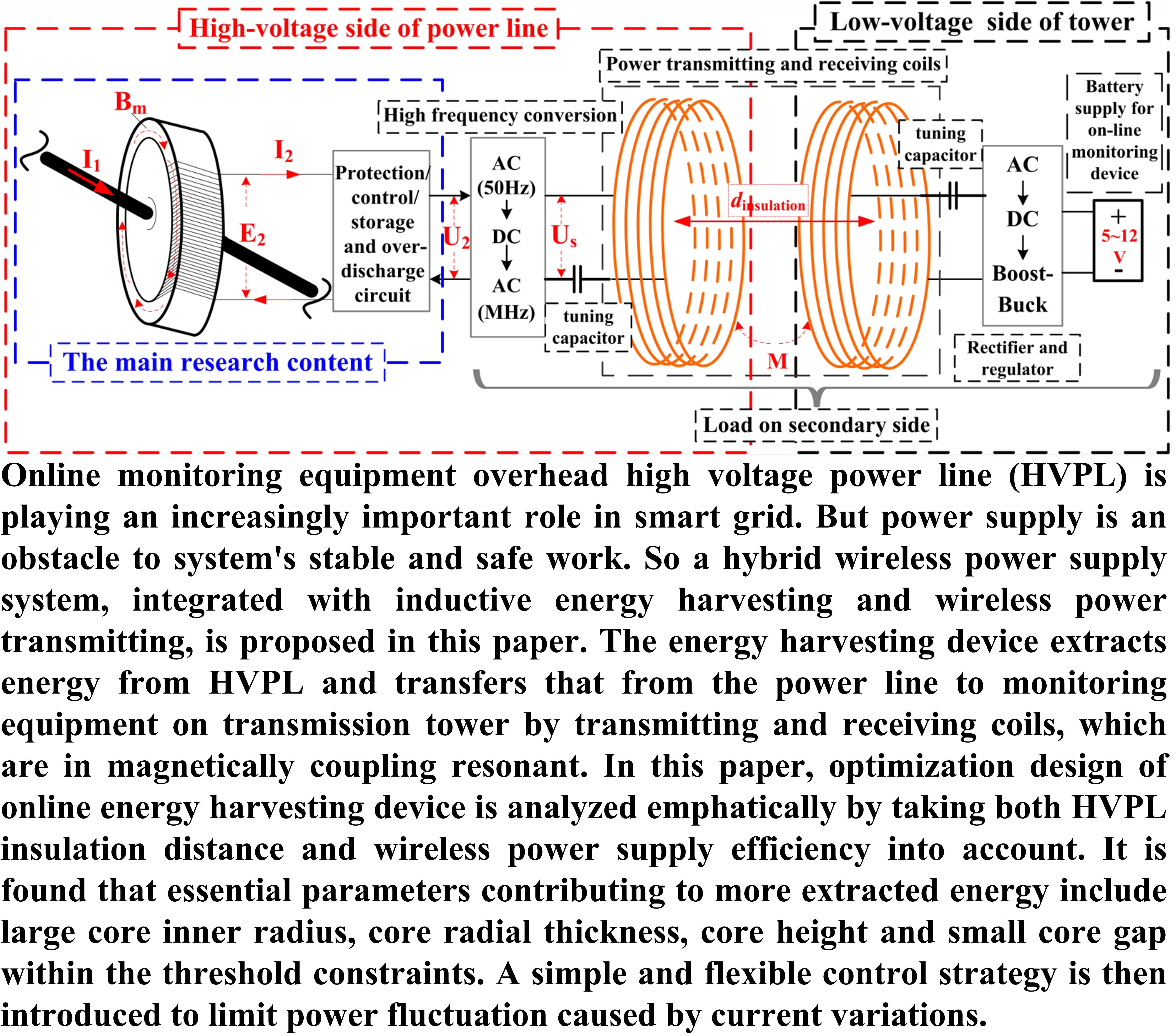
:
1. Introduction
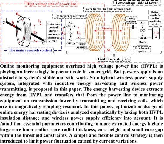
2. System Modeling and Analysis of the Wireless Power Supply System
3. Modeling and Optimization Design of Energy Harvesting Device
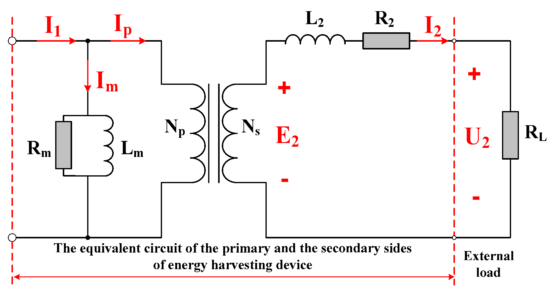
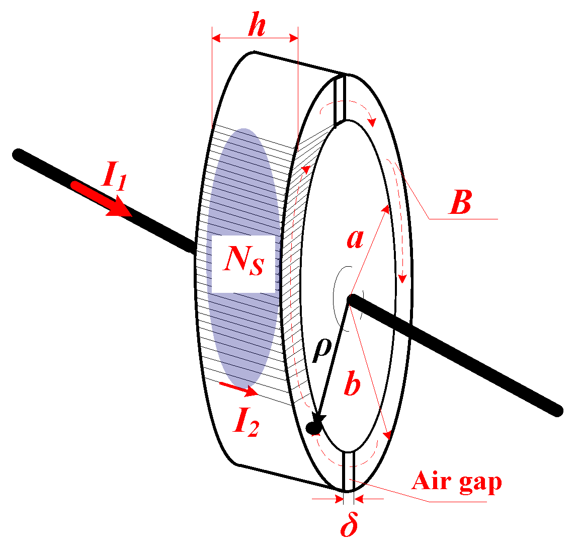
3.1. Theoretical Analysis
3.2. Parameters Optimization Design with Threshold Constraints
3.2.1. Parameter Optimization Design of the Core
3.2.2. Design Optimization of the Secondary Coil
- (1)
- The inner resistance of the coil should not be larger than the load resistance to ensure maximum output power:
- (2)
- Since the core is composed of two semicircles, a maximum Ns is achieved when the secondary coil covers half of the core at most, which means Ns is determined by the inner radius of the core:
4. Results
4.1. Simulation Analysis of the Energy Harvesting Device
- (1)
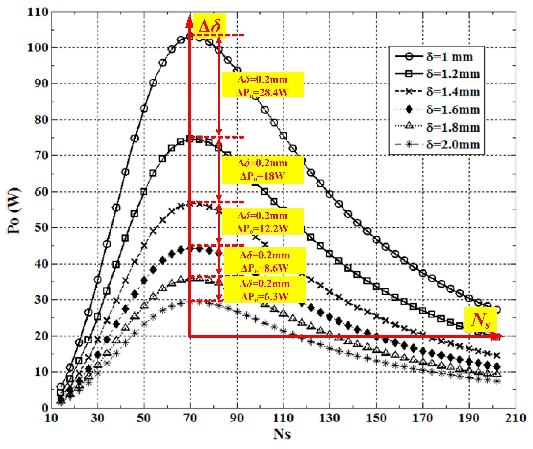
- According to Figure 7, both the optimal secondary coil turn Ns1 to achieve maximum output power and secondary coil turn Ns2 to ensure the minimum demanded power can be determined, which should comply with Ns2 > Ns1.
- (2)
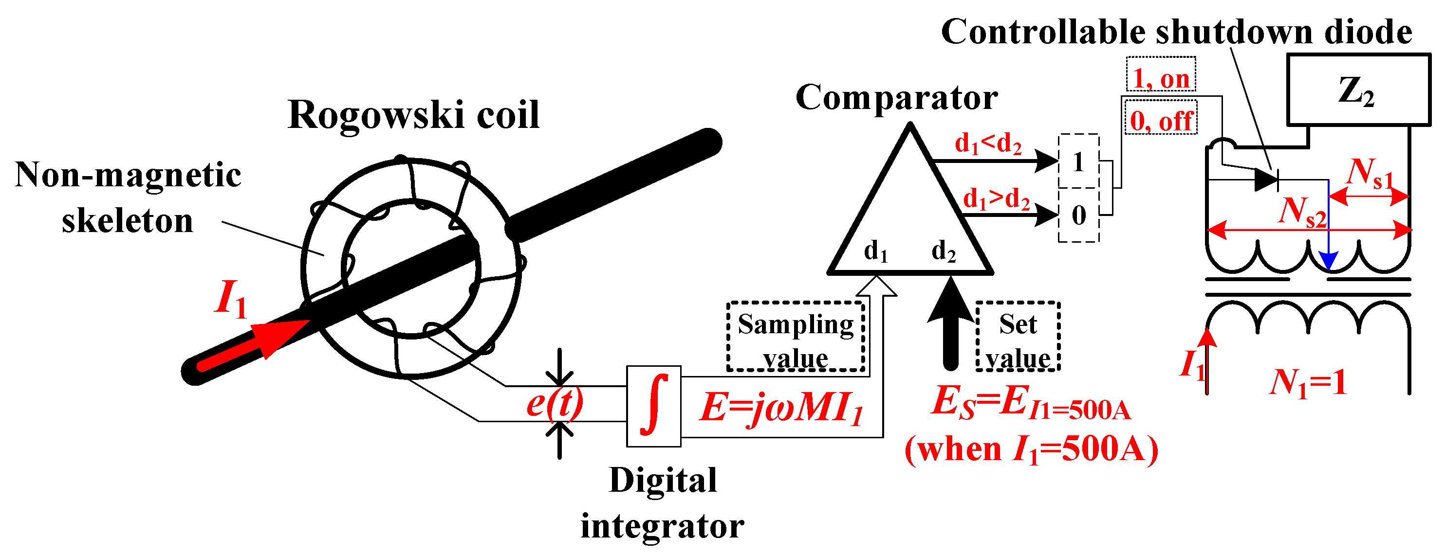
- Use a Rogowski coil to sample the current of HVPL in the form of induced voltage. A digital integrator is applied to transform the transient voltage signal e(t) into a stable signal E. The sampled voltage when the current equal to 500 A (less than or equal to the saturation current of core) is set as the standard value.
- (3)
- The digital comparator is in charge of comparing the sampled E with the standard value. It outputs high-level signals (“1”) when d1 < d2 and outputs low-level signals (“0”) when d1 > d2.
- (4)
- The diode is shut off when the comparator outputs high-level signals and the secondary coil turn is set to be Ns1 so that maximum output power is achieved. On the contrary, the diode is turned on and the secondary coil turn is set to be Ns2 so that minimum demanded power is acquired. The control strategy greatly reduces the impact of power increase on the load and realizes the goal to obtain relatively stable output power, regardless of current fluctuation.
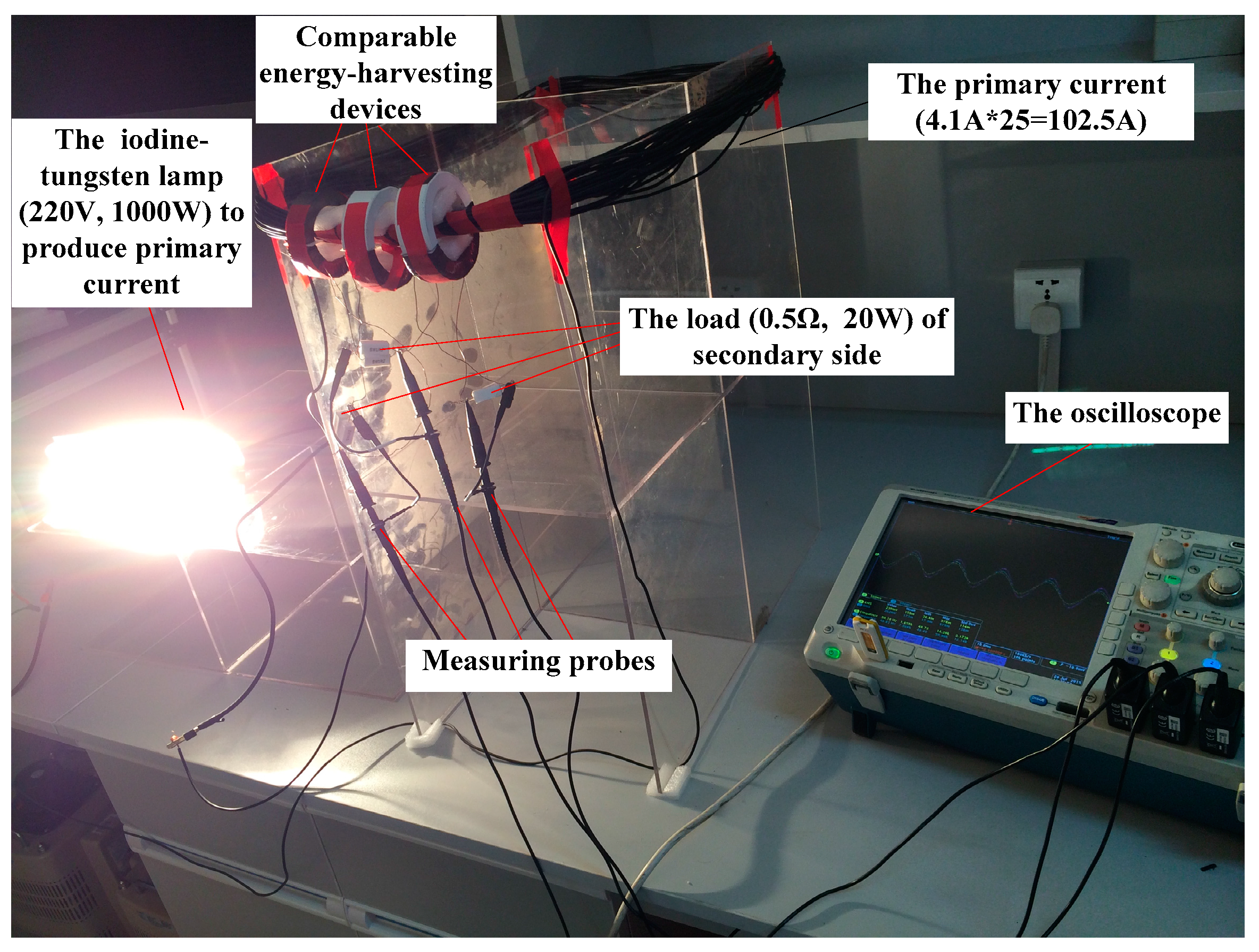
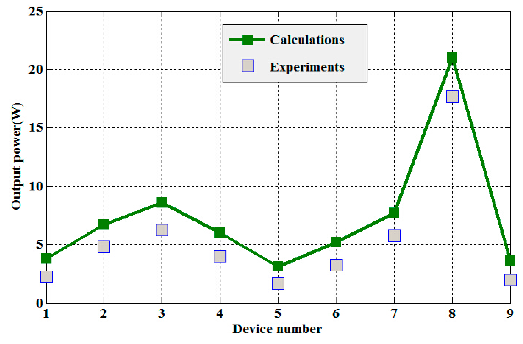
4.2. Experimental verification
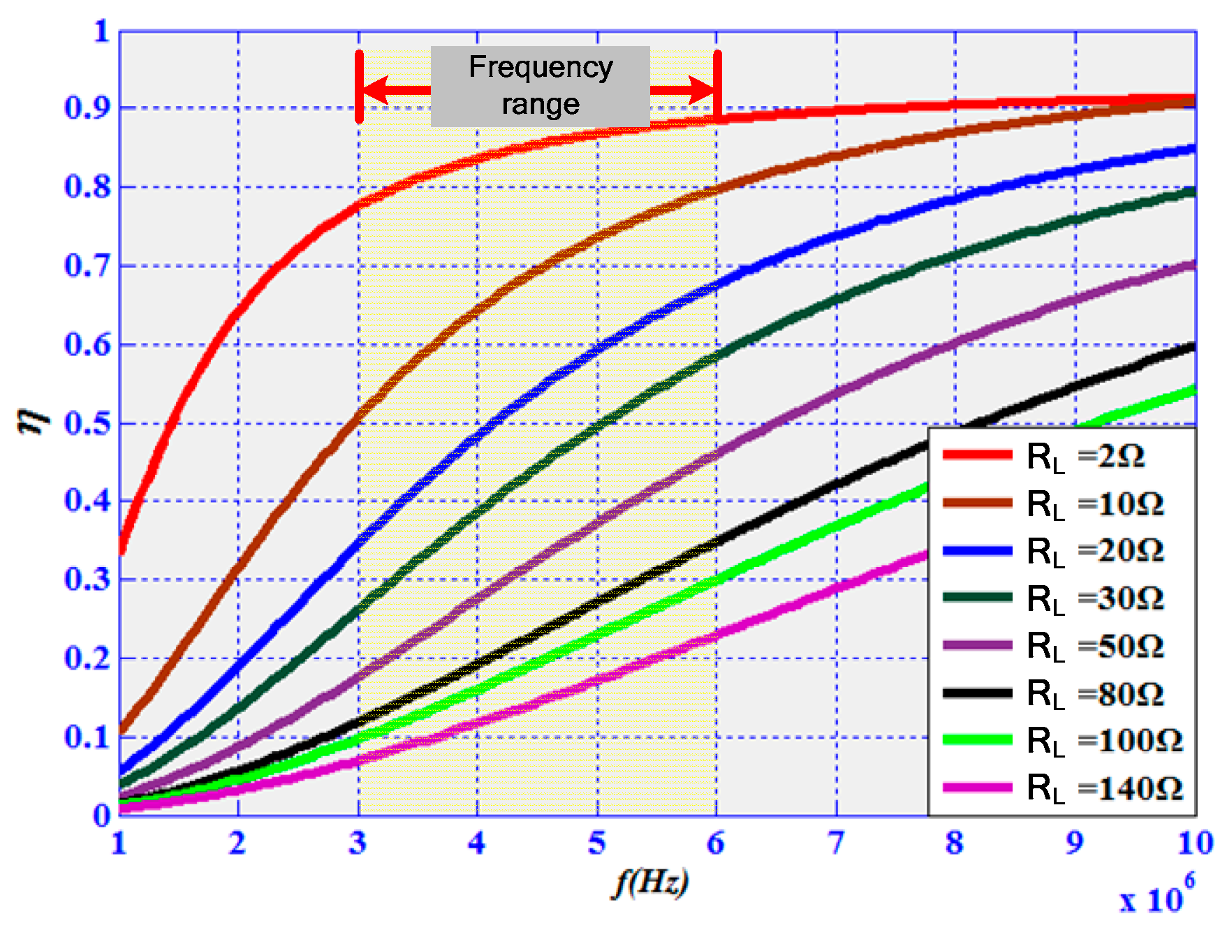
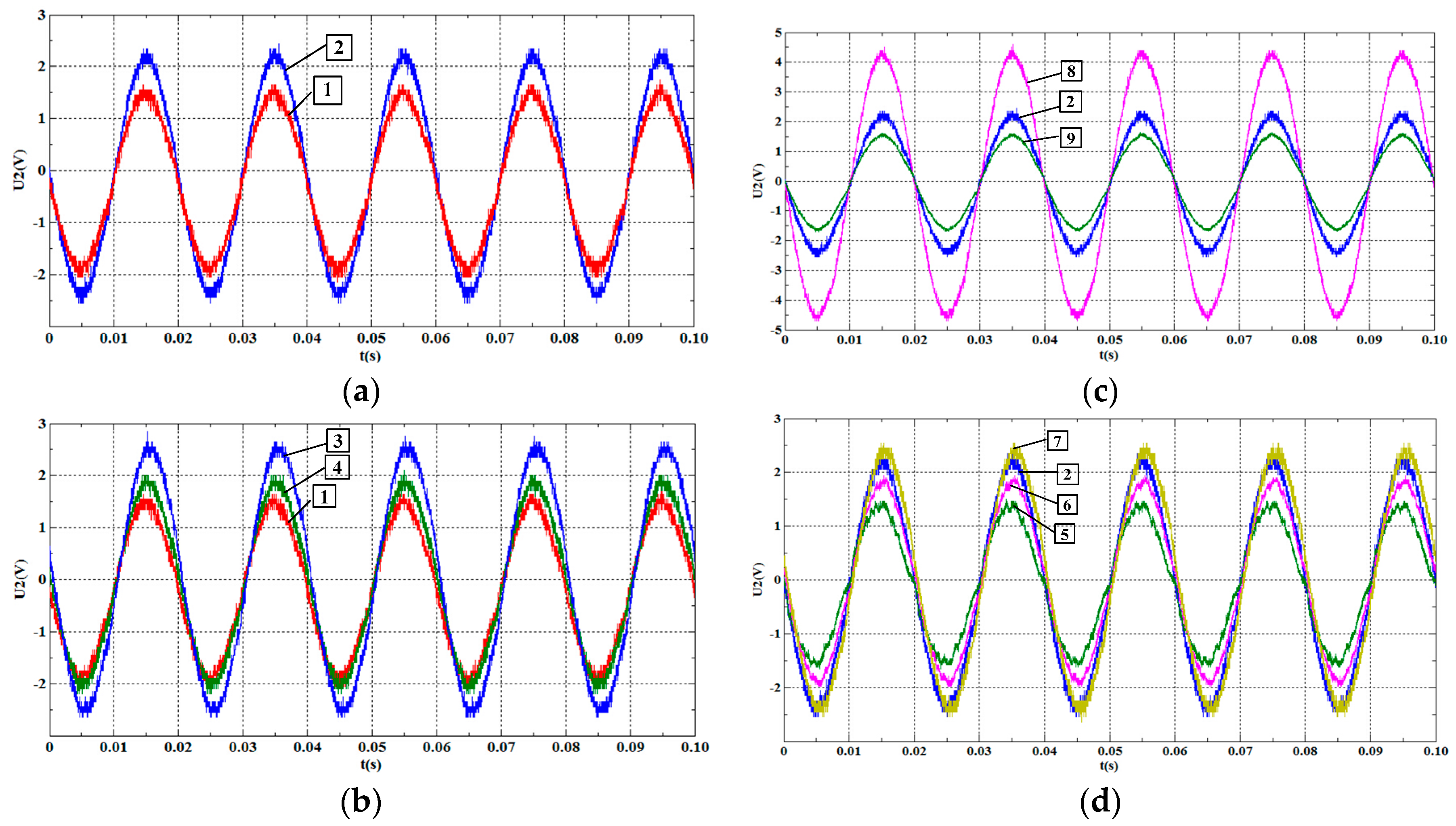
- (1)
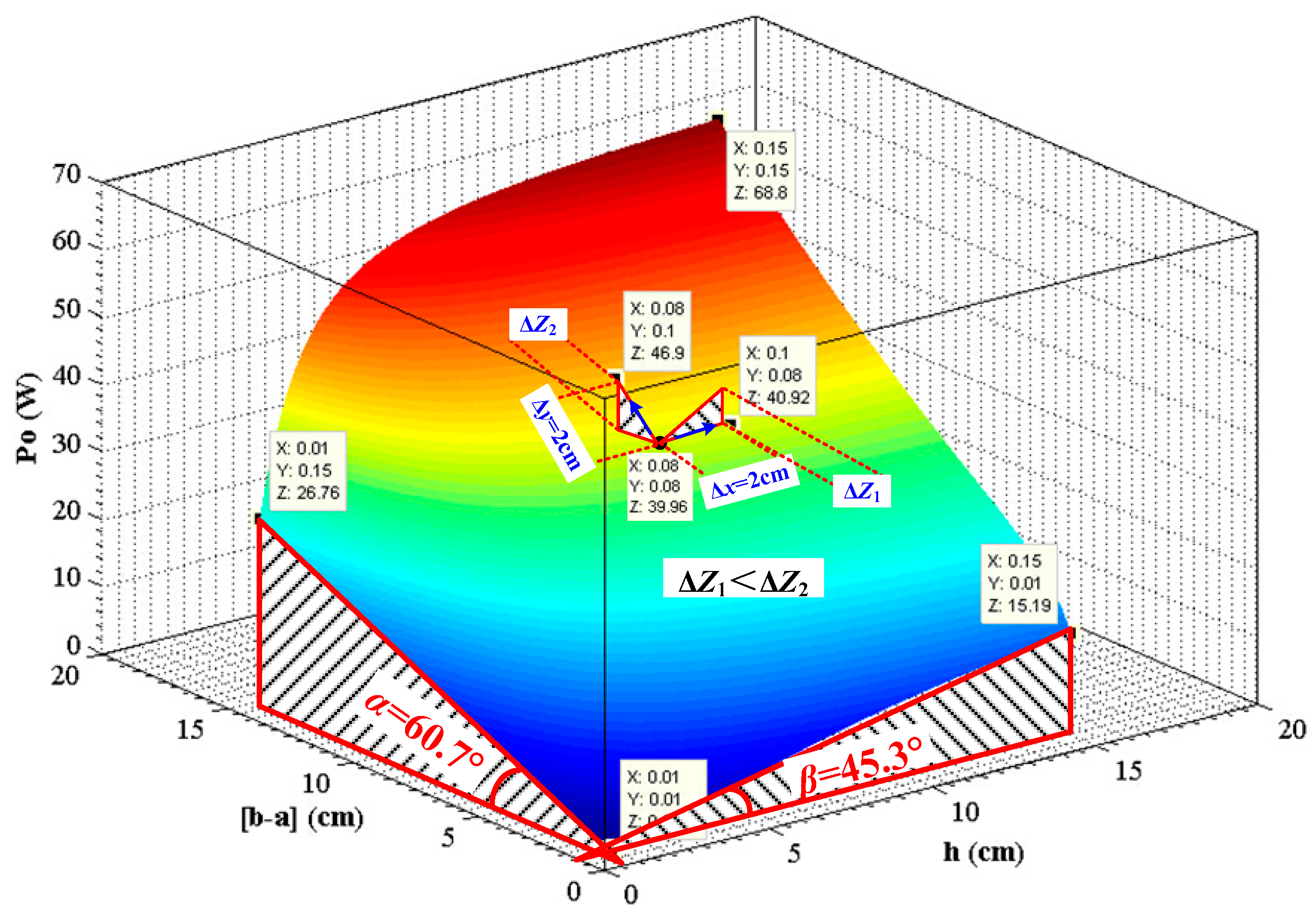
- Output power increases with the increase of core inner radius when other parameters remain certain;
- (2)
- The increase of core radial thickness (b-a) and core height h will contribute to the increase of output power but the former one has a more pronounced effect;
- (3)
- The smaller core gap is, the more output power the device can obtain once it holds true for Equation (16) and other parameters remain unchanged;
- (4)
- Maximum output power can be acquired with the optimized secondary coil turns when other parameters remain certain. In this experiment specifically, Po (Ns = 80) > Po (Ns = 100).
5. Discussion
6. Conclusions
Acknowledgments
Author Contributions
Conflicts of Interest
References
- Lu, S.; Repo, D.G.; Della, F.A.; Figuerola, A.L.; Pikkarainen, M. Real-time low voltage network monitoring-ICT architecture and field test experience. IEEE Trans. Smart Grid 2015, 6, 2002–2012. [Google Scholar] [CrossRef]
- Bobowski, J.S.; Ferdous, M.S.; Johnson, T.; Pikkarainen, M. Calibrated single-contact voltage sensor for high-voltage monitoring applications. IEEE Trans. Instrum. Meas. 2015, 64, 923–934. [Google Scholar] [CrossRef]
- Xia, J.; Jiale, S.; Deng, X.; Wang, L.; He, S.; Liu, K. Enhanced transmission line pilot impedance and pilot protection. IET Gener. Transm. Distrib. 2011, 5, 1240–1249. [Google Scholar] [CrossRef]
- Moser, M.J.; Bretterklieber, T.; Zangl, H.; Brasseur, G. Strong and weak electric field interfering: Capacitive icing detection and capacitive energy harvesting on a 220-kV high-voltage overhead power line. IEEE Trans. Ind. Electron. 2011, 58, 2597–2604. [Google Scholar] [CrossRef]
- Han, J.C.; Hu, J.; Yang, Y.; Wang, Z.X.; Wang, S.X.; He, J.L. A nonintrusive power supply design for self-powered sensor networks in the smart grid by scavenging energy from AC power line. IEEE Trans. Ind. Electron. 2015, 62, 4398–4407. [Google Scholar] [CrossRef]
- Moser, M.J.; Zangl, H.; Bretterklieber, T. An autonomous sensor system for monitoring of high voltage overhead power supply lines. Elektrotech. Informationstech. 2009, 126, 214–219. [Google Scholar] [CrossRef]
- Zhao, X.; Keutel, T.; Baldauf, M. Energy harvesting for a wireless-monitoring system of overhead high-voltage power lines. IET Gener. Transmiss. Distrib. 2013, 7, 101–107. [Google Scholar] [CrossRef]
- Wu, Z.; Wen, Y.; Li, P. A Power Supply of Self-Powered Online Monitoring Systems for Power Cords. IEEE Trans. Energy Convers. 2013, 28, 921–928. [Google Scholar] [CrossRef]
- Dai, Y.; Chen, K.; Lin, D.; Cheng, Y.C.; Nie, M.; Wang, W. Design of induced power apparatus for monitoring system of dynamic increasing capacity of high-voltage transmission lines. In Proceedings of the 2012 International Conference on Condition Monitoring and Diagnosis, Bali, Indonesia, 23–27 September 2012.
- He, Z.; Nie, S.; Qu, G.; Liu, Y.; Sheng, G.; Jiang, X. The design of CT energy harvesting power supply based on phase-controlled method. In Proceedings of the 2012 Asia-Pacific Power and Energy Engineering Conference, Shanghai, China, 1–5 March 2012.
- Yao, M.; Zhao, M. Research on electric energy harvesting from high-voltage transmission line. In Proceedings of the 2013 3rd International Conference on Electric Power and Energy Conversion Systems, Istanbul, Turkey, 2–4 October 2013.
- Banting, J.F.; Mcbee, B.W. Power Line Energy Harvesting Power Supply. U.S. Patent 20100084920 B2, 26 November 2013. Available online: https://patentscope.wipo.int/search/zh/detail.jsf?docId=US43743066&recNum=1&maxRec=&office=&prevFilter=&sortOption=&queryString=&tab=NationalBiblio (accessed on 26 November 2013). [Google Scholar]
- Yuan, S.; Huang, Y.; Zhou, J.F.; Xu, Q.; Song, C.Y.; Thompson, P. Magnetic field energy harvesting under overhead power lines. IEEE Trans. Power Electron. 2015, 30, 6191–6202. [Google Scholar] [CrossRef]
- Van Schalkwyk, J.A.; Hancke, G.P. Energy harvesting for wireless sensors from electromagnetic fields around overhead power lines. In Proceedings of the 2012 IEEE International Symposium on Industrial Electronics, Hangzhou, China, 28–31 May 2012.
- Zhang, D. Potential Power Supply and Signal Transmission System of Online Monitoring Device on High Voltage Transmission Line. CN Patent 201210224012.3, 22 January 2014. [Google Scholar]
- Kurs, A.; Karalis, A.; Moffatt, R.; Joannopoulos, J.D.; Fisher, P.; Soljacic, M. Wireless power transfer via strongly coupled magnetic resonance. Science 2007, 317, 83–86. [Google Scholar] [CrossRef] [PubMed]
- Li, P.; Wen, Y.; Zhang, Z.; Pan, S. A high-efficiency management circuit using multi-winding up-conversion current transformer for power-line energy harvesting. IEEE Trans. Ind. Electron. 2015, 62, 6327–6335. [Google Scholar] [CrossRef]
- Zhang, W.; Wong, S.C.; Tse, C.K.; Cheng, Q.H. Analysis and comparison of secondary series-and parallel-compensated inductive power transfer systems operating for optimal efficiency and load-independent voltage-transfer ratio. IEEE Trans. Power Electron. 2014, 29, 2979–2990. [Google Scholar] [CrossRef]
- Moorey, C.; Holderbaum, W.; Potter, B. Investigation of high-efficiency wireless power transfer criteria of resonantly-coupled loops and dipoles through analysis of the figure of merit. Energies 2015, 8, 11342–11362. [Google Scholar] [CrossRef]
- Zhang, Z.; Chau, K.T.; Liu, C.H.; Li, F.H.; Ching, T.W. Quantitative Analysis of Mutual Inductance for Optimal Wireless Power Transfer via Magnetic Resonant Coupling. IEEE Trans. Magn. 2014, 50, 1–4. [Google Scholar] [CrossRef] [Green Version]
- Huang, X.L.; Wang, W.; Tan, L.L.; Zhao, J.M.; Zhou, Y.L. Study of transmission performance on strong coupling wireless power transfer system in free position. In Proceedings of the PIERS 2012 Electromagnetics Research Symposium, Moscow, Russia, 23 August 2012.
- Duong, T.P.; Lee, J.W. A dynamically adaptable impedance-matching system for midrange wireless power transfer with misalignment. Energies 2015, 8, 7593–7617. [Google Scholar] [CrossRef]
- Houtzager, E.; Rietveld, G.; Dessens, J.; Heemskerk, M.; van den Brom, H.E. Design of a non-invasive current sensor for application on high voltage lines. In Proceedings of the 2014 IEEE Conference on Precision Electromagnetic Measurements, Rio de Janeiro, Brazil, 24–29 August 2014.
- Chen, T.M.; Liu, B.A.; Luo, Y.L. The Inductance of Coils with Special Shape and Special Purpose, 3rd ed.; Machinery Industry Press: Beijing, China, 1992; pp. 373–416. [Google Scholar]


| Device Number | a (cm) | (b-a) (cm) | h (cm) | δ (mm) | Ns | PL (W) |
|---|---|---|---|---|---|---|
| 1 | 2.25 | 1.0 | 1.65 | 1 | 100 | 2.25 |
| 2 | 2.75 | 1.0 | 1.65 | 1 | 100 | 4.84 |
| 3 | 2.25 | 1.1 | 1.65 | 1 | 100 | 6.25 |
| 4 | 2.25 | 1.0 | 1.75 | 1 | 100 | 4.00 |
| 5 | 2.75 | 1.0 | 1.65 | 1 | 30 | 1.69 |
| 6 | 2.75 | 1.0 | 1.65 | 1 | 50 | 3.24 |
| 7 | 2.75 | 1.0 | 1.65 | 1 | 80 | 5.76 |
| 8 | 2.75 | 1.0 | 1.65 | 0.5 | 100 | 17.64 |
| 9 | 2.75 | 1.0 | 1.65 | 2 | 100 | 1.96 |
© 2016 by the authors; licensee MDPI, Basel, Switzerland. This article is an open access article distributed under the terms and conditions of the Creative Commons by Attribution (CC-BY) license (http://creativecommons.org/licenses/by/4.0/).
Share and Cite
Wang, W.; Huang, X.; Tan, L.; Guo, J.; Liu, H. Optimization Design of an Inductive Energy Harvesting Device for Wireless Power Supply System Overhead High-Voltage Power Lines. Energies 2016, 9, 242. https://doi.org/10.3390/en9040242
Wang W, Huang X, Tan L, Guo J, Liu H. Optimization Design of an Inductive Energy Harvesting Device for Wireless Power Supply System Overhead High-Voltage Power Lines. Energies. 2016; 9(4):242. https://doi.org/10.3390/en9040242
Chicago/Turabian StyleWang, Wei, Xueliang Huang, Linlin Tan, Jinpeng Guo, and Han Liu. 2016. "Optimization Design of an Inductive Energy Harvesting Device for Wireless Power Supply System Overhead High-Voltage Power Lines" Energies 9, no. 4: 242. https://doi.org/10.3390/en9040242