
Control and Optimization of a Variable-Pitch Quadrotor with Minimum Power Consumption

Abstract
:
1. Introduction
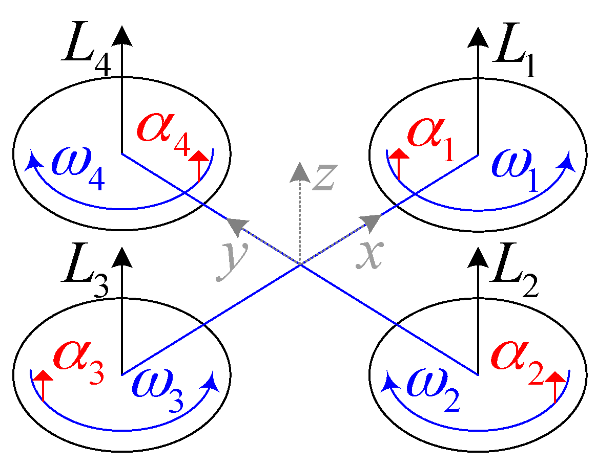
2. The Control and Optimization Problem Statement of the Variable-Pitch Quadrotor
3. The Steady-state Identification Method of the Electric Variable-pitch Propeller
| The Steady-state Identification Algorithm: |
| Input: |
| The steady-state sample set , where the subscript, k , denotes the sample number, and . Moreover, The chosen satisfies the constraint condition , where , and is an optional positive value. |
| Output: |
| and , which are the estimates of and , respectively. |
| Steps: |
| (1) Calculate , where ; |
| (2) Calculate ; |
| (3) Calculate |
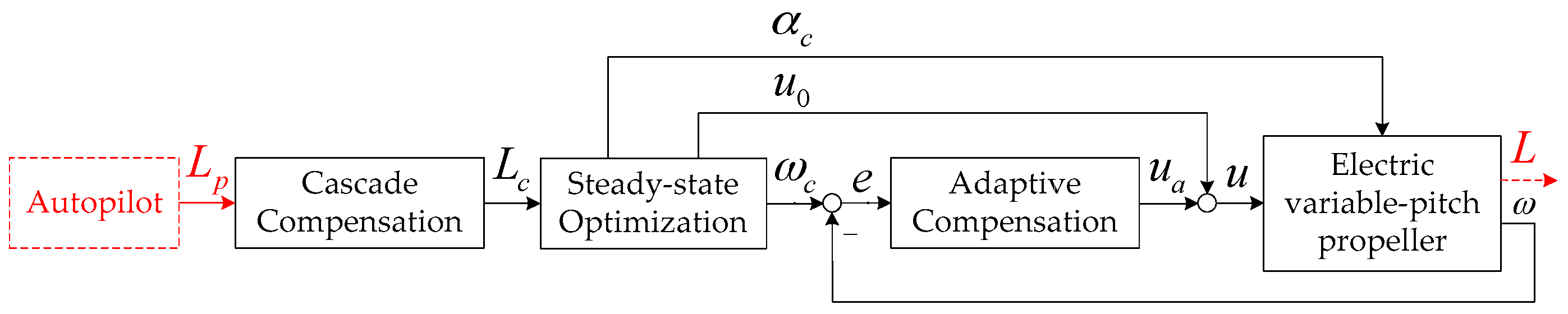
4. The Control and Optimization Strategy for the Electric Variable-Pitch Propeller
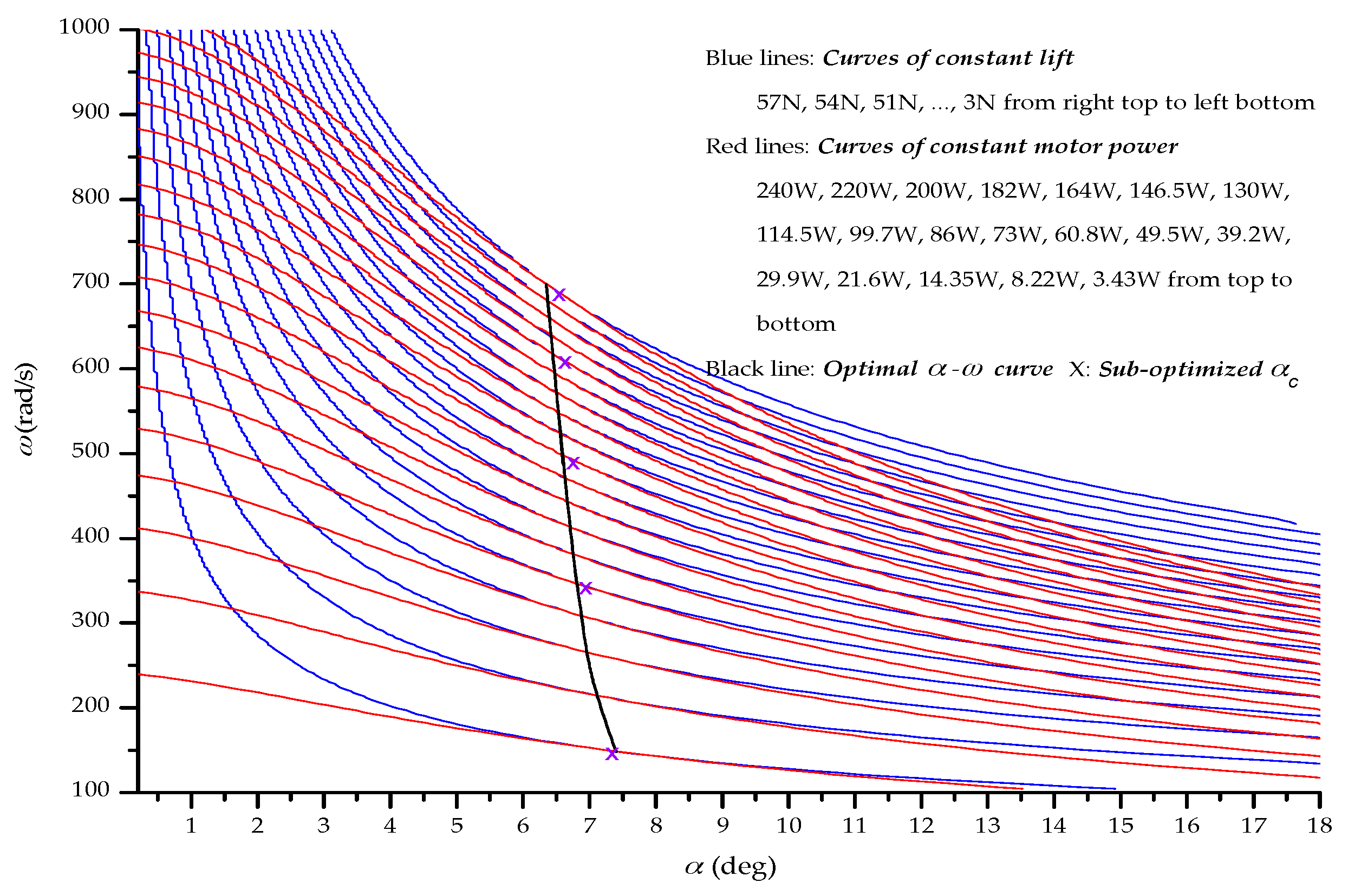
4.1. The Steady-State Control and Optimization Scheme with Minimum Power Consumption
| The Online Iterative Algorithm: |
| Input: |
| and , where denote the and control instants, respectively; is the optional minimum increment of . |
| Output: |
| . |
| Steps:(1) |
| (1) , and ; |
| (2) If and , then |
| Go to Step 4; |
| Else |
| Go to Step 3; |
| End |
| (3) If > , then |
| ; |
| Else |
| ; |
| End |
| Return to Step 2; |
| (4) Calculate . |
4.2. The Adaptive Compensation Scheme
4.3. The Cascade Compensation Scheme
5. The Direct Lift-based Flight Control Strategy for the Variable-Pitch Quadrotor
5.1. The Direct Lift-based Height Control Scheme
5.2. The Direct Lift-based Attitude Control Scheme
6. Experimental Tests
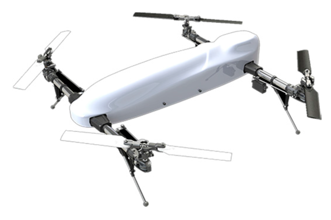
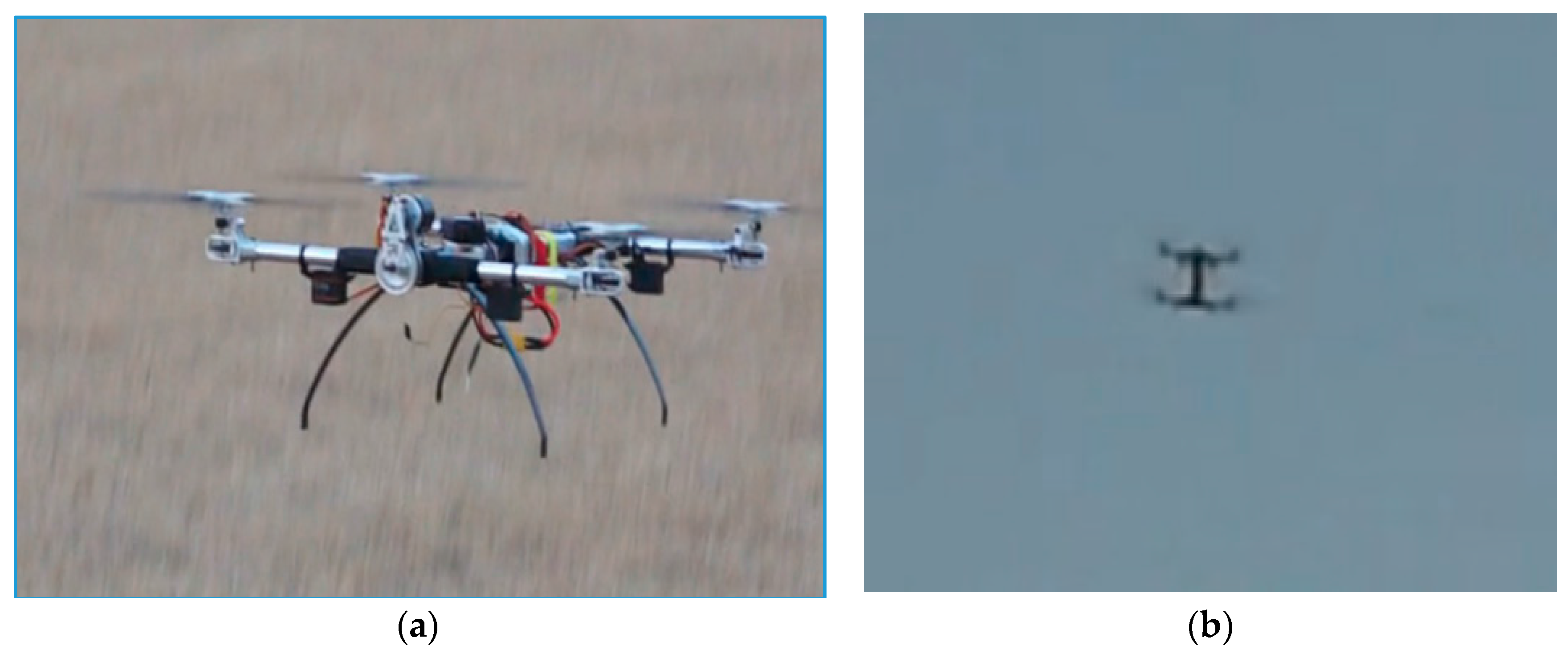
6.1. The Experimental Setup and Description
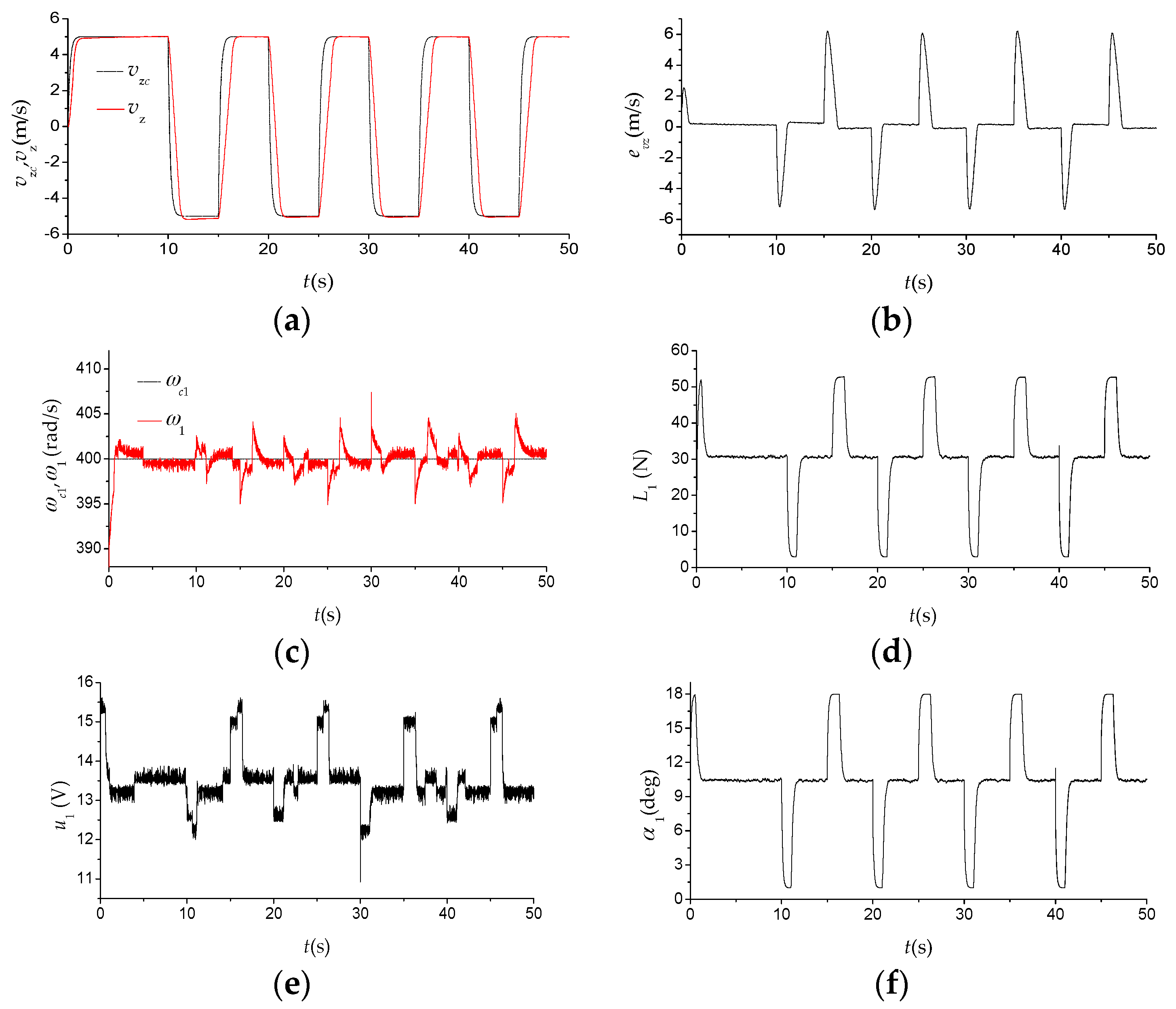
6.2. Vertical Flight and Endurance Tests
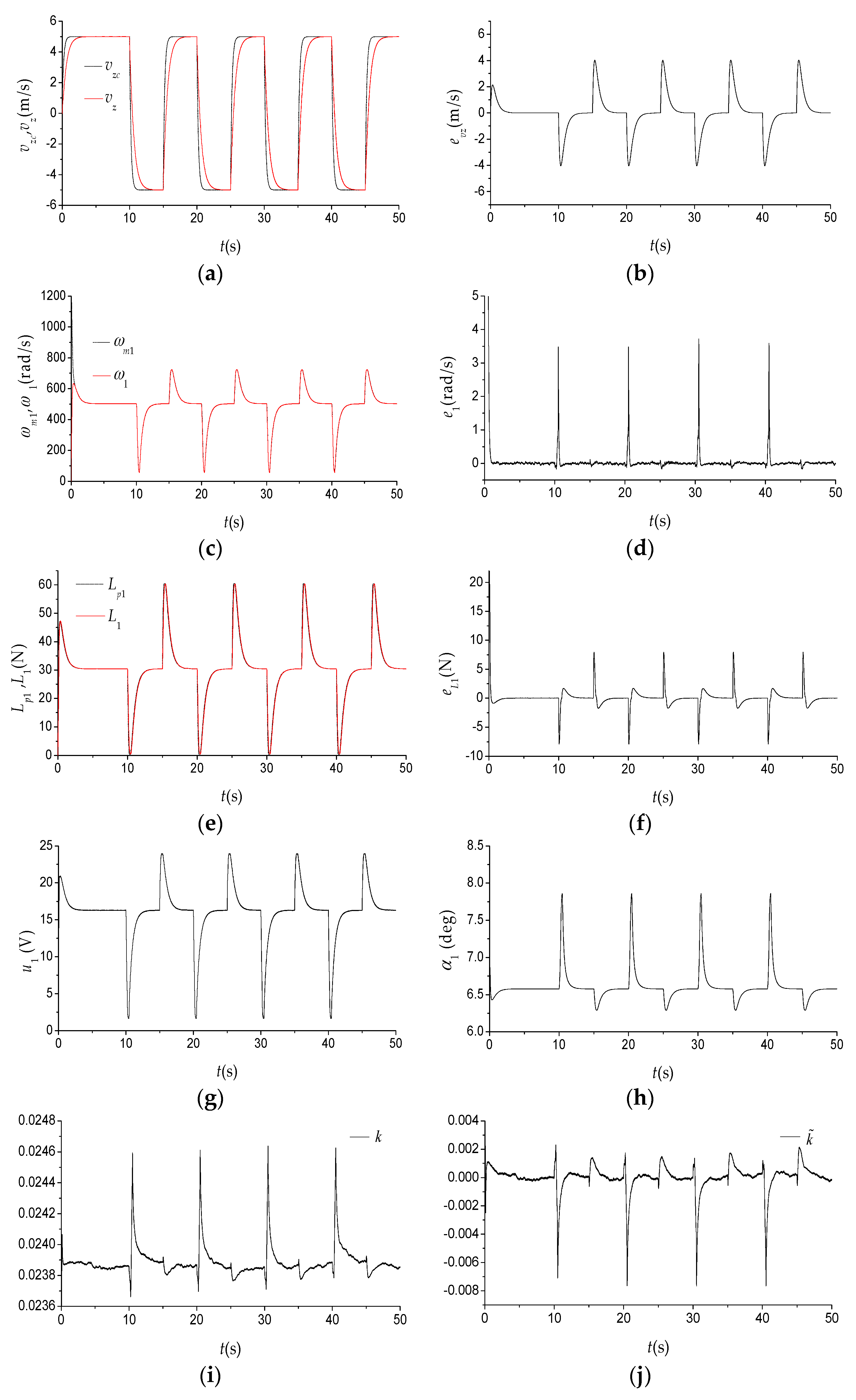
6.2.1. Experimental Tests of the Proposed Method
- (1)
- The estimates of aerodynamic parameters: ;
- (2)
- Adaptive compensation in the rotational speed loop: ;
- (3)
- Cascade compensation in the lift force loop: ;
- (4)
- Direct lift-based height control scheme: ;
- (5)
- Direct lift-based attitude control scheme: , ;
- (6)
- Longitudinal position control scheme: , where is the position error along the body axis, , and so does the lateral position control scheme. A series of real-time experimental tests are then conducted based on the above assumptions.
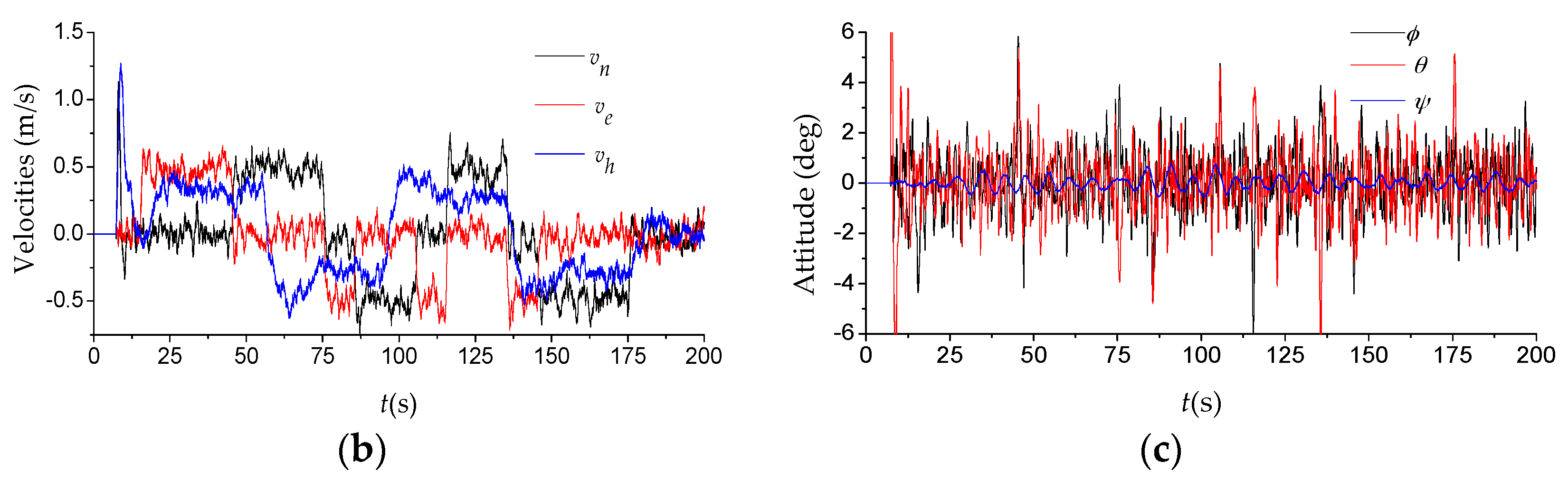
6.2.2. Experimental Tests of the Conventional Method with Constant Rotational Speed
- (1)
- Rotational speed control scheme (optimal proportional-integral control): proportional and integral coefficients equal to 0.85 and 1.95;
- (2)
- Vertical velocity control scheme (optimal proportional-integral-differential control): proportional, integral and differential coefficients equal to 2.5, 1.0 and 0.2.
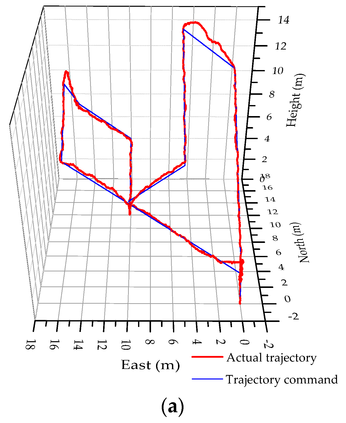
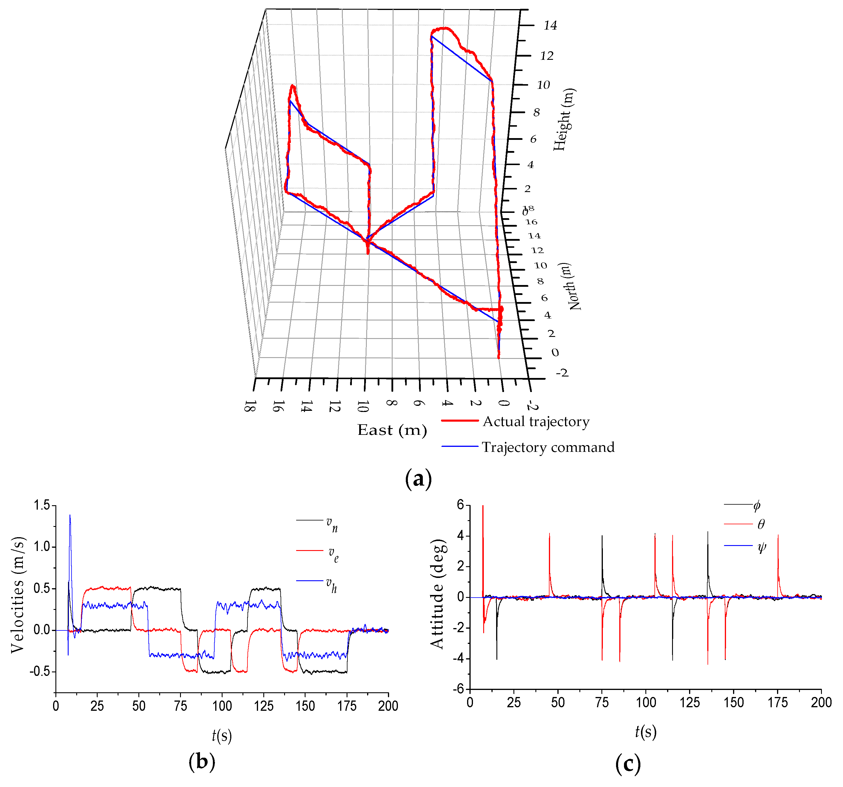
6.3. Positioning Accuracy Tests
7. Conclusions
Acknowledgments
Author Contributions
Conflicts of Interest
References
- Altug, E.; Ostrowski, J.P.; Mahony, R. Control of a Quadrotor Helicopter Using Visual Feedback. In Proceedings of the 2002 IEEE International Conference on Robotics and Automation (ICRA), Washington, DC, USA, 10–17 May 2002; Volume 1, pp. 72–77.
- Tayebi, A.; McGilvray, S. Attitude stabilization of a VTOL quadrotor aircraft. IEEE Trans. Control Syst. Technol. 2006, 14, 562–571. [Google Scholar] [CrossRef]
- Madani, T.; Benallegue, A. Control of a Quadrotor Mini-Helicopter via Full State Backstepping Technique. In Proceedings of the 2006 45th IEEE Conference on Decision and Control, San Diego, CA, USA, 13–15 December 2006; pp. 1515–1520.
- How, J.P.; Bethke, B.; Frank, A.; Dale, D.; Vian, J. Real-time indoor autonomous vehicle test environment. IEEE Trans. Control Syst. Mag. 2008, 28, 51–64. [Google Scholar] [CrossRef]
- Pounds, P.; Mahony, R.; Corke, P. Modeling and control of a large quadrotor robot. Control Eng. Pract. 2010, 18, 691–699. [Google Scholar] [CrossRef] [Green Version]
- Ryll, M.; Bulthoff, H.H.; Giordano, P.R. First Flight Tests for a Quadrotor UAV with Tilting Propellers. In Proceedings of the 2013 IEEE International Conference on Robotics and Automation (ICRA), Karlsruhe, Germany, 6–10 May 2013; pp. 295–302.
- Sheng, S.; Sun, C. Design of a Stability Augmentation System for an Unmanned Helicopter Based on Adaptive Control Techniques. Appl. Sci. 2015, 5, 575–586. [Google Scholar] [CrossRef]
- Sheng, S.; Sun, C. A Near-Hover Adaptive Attitude Control Strategy of a Ducted Fan Micro Aerial Vehicle with Actuator Dynamics. Appl. Sci. 2015, 5, 666–681. [Google Scholar] [CrossRef]
- Sheng, S.; Sun, C.; Zhao, H. Indirect Adaptive Attitude Control for a Ducted Fan Vertical Takeoff and Landing Microaerial Vehicle. Math. Probl. Eng. 2015, 2015. [Google Scholar] [CrossRef]
- Bouabdallah, S.; Murrieri, P.; Siegwart, R. Towards Autonomous Indoor Micro VTOL. Auton. Robots 2005, 18, 171–183. [Google Scholar] [CrossRef]
- Bresciani, T. Modeling, Identification and Control of a Quadrotor Helicopter. Master’s Thesis, Lund University, Lund, Sweden, 1 January 2008. [Google Scholar]
- Shirsat, A.R. Modeling and Control of a Quadrotor UAV. Master’s Thesis, Arizona State University, Tempe, AZ, USA, May 2015. [Google Scholar]
- Erginer, B.; Altug, E. Modeling and PD control of a quadrotor VTOL vehicle. In Proceedings of the 2007 IEEE Intelligent Vehicles Symposium, Istanbul, Turkey, 13–15 June 2007; pp. 894–899.
- Walid, M.; Slaheddine, N.; Mohamed, A.; Lamjed, B. Modeling and Control of a Quadrotor UAV. In Proceeding of the 2014 15th International Conference on Sciences and Techniques of Automatic Control and Computer Engineering (STA), Hammamet, Tunisia, 21–23 December 2014; pp. 343–348.
- Alexis, K.; Nikolakopoulos, G.; Tzes, A. Model Predictive Quadrotor Control: Attitude, Altitude and Position Experimental Studies. IET Control Theory Appl. 2012, 6, 1812–1827. [Google Scholar] [CrossRef]
- Kim, J.; Kang, M.S.; Park, S. Accurate Modeling and Robust Hovering Control for a Quad–Rotor VTOL Aircraft. In Proceeding of the Selected Papers from the 2nd International Symposium on UAVs, Reno, NV, USA, 8–10 June 2009; pp. 9–26.
- Hoffmann, G.M.; Huang, H.; Waslander, S.L.; Tomlin, C.J. Quadrotor Helicopter Flight Dynamics and Control: Theory and Experiment. In Proceeding of the AIAA Guidance, Navigation, and Control Conference, Hilton Head, SC, USA, 21–22 August 2007; Volume 2.
- Bouabdallah, S. Design and Control of Quadrotors with Application to Autonomous Flying. Ph.D. Thesis, Swiss Federal Institute of Technology, Lausanne, Switzerland, 10 January 2007. [Google Scholar]
- Cutler, M.; Ure, N.K.; Michini, B.; How, J.P. Comparison of Fixed and Variable Pitch Actuators for Agile Quadrotors. In Proceeding of the AIAA Conference on Guidance, Navigation and Control and Co-Located Conferences (GNC), Portland, OR, USA, 8–11 August 2011. [CrossRef] [Green Version]
- Cutler, M. Design and Control of an Autonomous Variable-Pitch Quadrotor Helicopter. Ph.D. Thesis, Massachusetts Institute of Technology, Cambridge, MA, USA, 23 August 2012. [Google Scholar]
- Riccardi, F.; Panizza, P.; Lovera, M. Identification of the Attitude Dynamics for A Variable-Pitch Quadrotor UAV. In Proceeding of the European Rotorcraft Forum (ERF) 2014, Southampton, UK, 2–5 September 2014.
- Fresk, E. Modeling, Control and Experimentation of a Variable Pitch Quadrotor. Master’s Thesis, Luleå University of Technology, Luleå, Sweden, 2013. [Google Scholar]
- Michini, B.; Redding, J.; Ure, N.K.; Cutler, M.; How, J.P. Design and Flight Testing of an Autonomous Variable-pitch Quadrotor. In Proceeding of the 2011 IEEE International Conference on Robotics and Automation (ICRA), Shanghai, China, 9–13 May 2011; pp. 2978–2979.
- Cutler, M.; How, J.P. Actuator Constrained Trajectory Generation and Control for Variable-Pitch Quadrotors. In Proceeding of the AIAA Guidance, Navigation, and Control Conference (GNC), Minneapolis, MN, USA, 13–16 August 2012.
- Bristeau, P.J.; Martin, P.; Salaun, E.; Petit, N. The Role of Propeller Aerodynamics in the Model of a Quadrotor UAV. In Proceeding of the European Control Conference, Budapest, Hungary, 23–26 August 2009.
- Drela, M. QPROP Users Guide. 2009. Available online: http://web.mit.edu/drela/Public/web/qprop/ (accessed on 10 November 2015).
- Hanselman, D.C. Brushless Permanent Magnet Motor Design, 2nd ed.; The Writers' Collective: Cranston, RI, USA, 2003. [Google Scholar]


| Configuration | Variable | Value |
|---|---|---|
| XM5060EA-9 motor and 16 inch diameter propeller | 2.73 × 10⁻⁸ | |
| 1.13 × 10⁻⁶ | ||
| 2.93 × 10⁻⁵ | ||
| 2.37 × 10⁻² | ||
| −2.97 × 10⁻² | ||
| 0.78 |
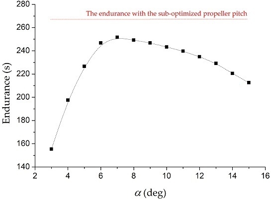
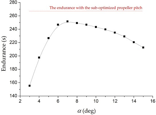
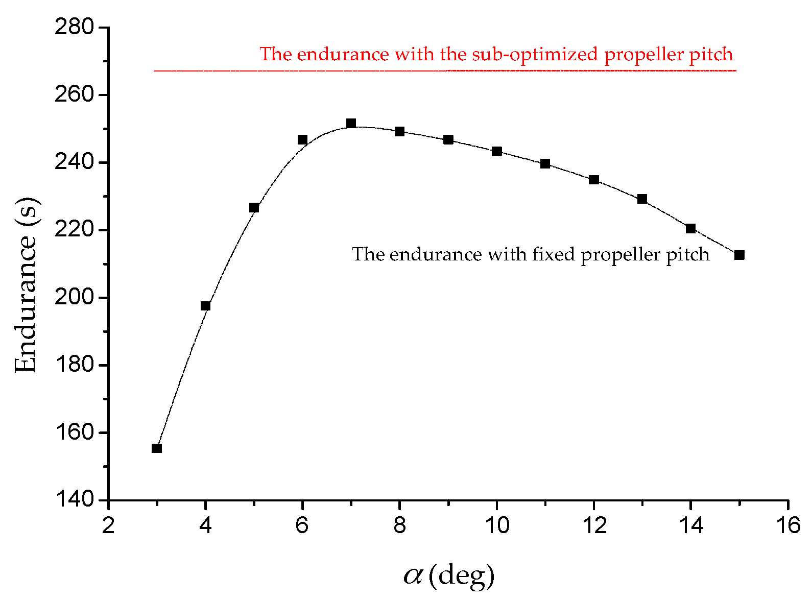
| Battery Capacity | (deg) | Endurance (s) |
|---|---|---|
| 5000 mAh | Sub-optimized value | 267.30 |
| 3 | 155.36 | |
| 4 | 197.50 | |
| 5 | 226.61 | |
| 6 | 246.72 | |
| 7 | 251.65 | |
| 8 | 249.22 | |
| 9 | 246.77 | |
| 10 | 243.27 | |
| 11 | 239.70 | |
| 12 | 234.91 | |
| 13 | 229.19 | |
| 14 | 220.52 | |
| 15 | 212.58 |
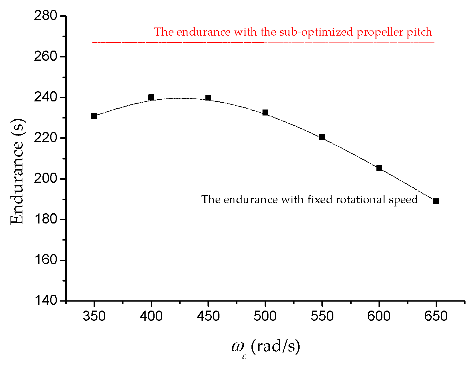
| Battery Capacity | (rad/s) | Endurance (s) |
|---|---|---|
| 5000 mAh | 350 | 230.95 |
| 400 | 240.09 | |
| 450 | 239.89 | |
| 500 | 232.52 | |
| 550 | 220.43 | |
| 600 | 205.31 | |
| 650 | 189.06 |
© 2016 by the authors; licensee MDPI, Basel, Switzerland. This article is an open access article distributed under the terms and conditions of the Creative Commons by Attribution (CC-BY) license (http://creativecommons.org/licenses/by/4.0/).
Share and Cite
Sheng, S.; Sun, C. Control and Optimization of a Variable-Pitch Quadrotor with Minimum Power Consumption. Energies 2016, 9, 232. https://doi.org/10.3390/en9040232
Sheng S, Sun C. Control and Optimization of a Variable-Pitch Quadrotor with Minimum Power Consumption. Energies. 2016; 9(4):232. https://doi.org/10.3390/en9040232
Chicago/Turabian StyleSheng, Shouzhao, and Chenwu Sun. 2016. "Control and Optimization of a Variable-Pitch Quadrotor with Minimum Power Consumption" Energies 9, no. 4: 232. https://doi.org/10.3390/en9040232