4.2. Wavelet Results
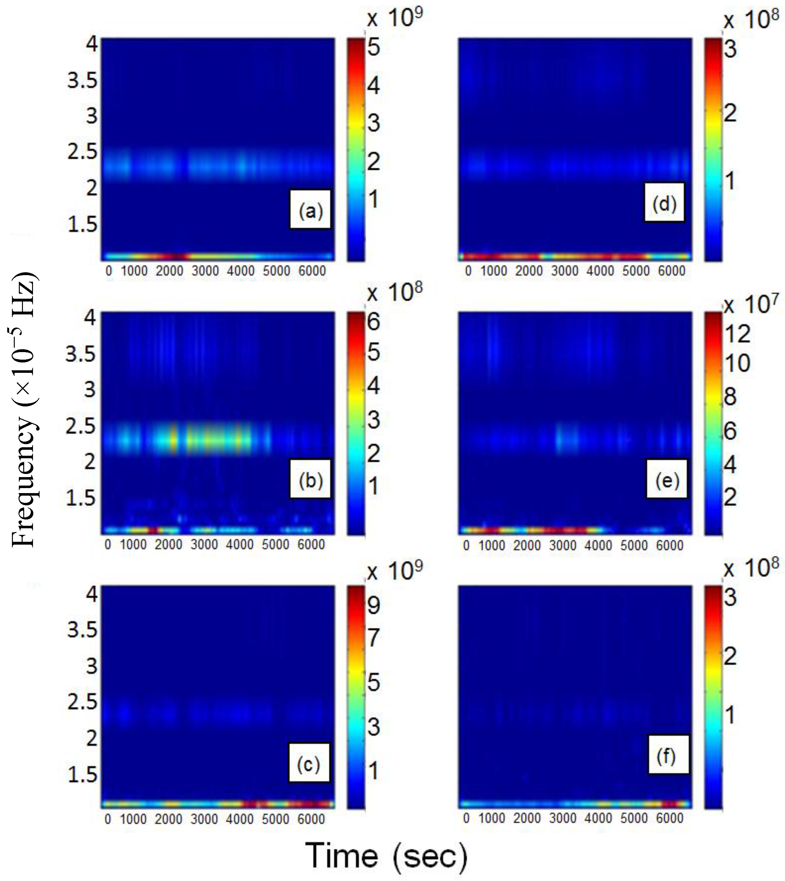
In order to make a quantitative comparison with the FFT results on power signals and to check whether taking into account also the non-stationary behavior can lead to different results, we have also used the complex Morlet wavelet mother as prototype of WT. For technical details about the basic formalism, see [
25]. Note that this choice is not restrictive because other kinds of WT existing in literature would lead to very similar results. The calculated time-frequency behavior for both active and reactive powers is illustrated in
Figure 3.
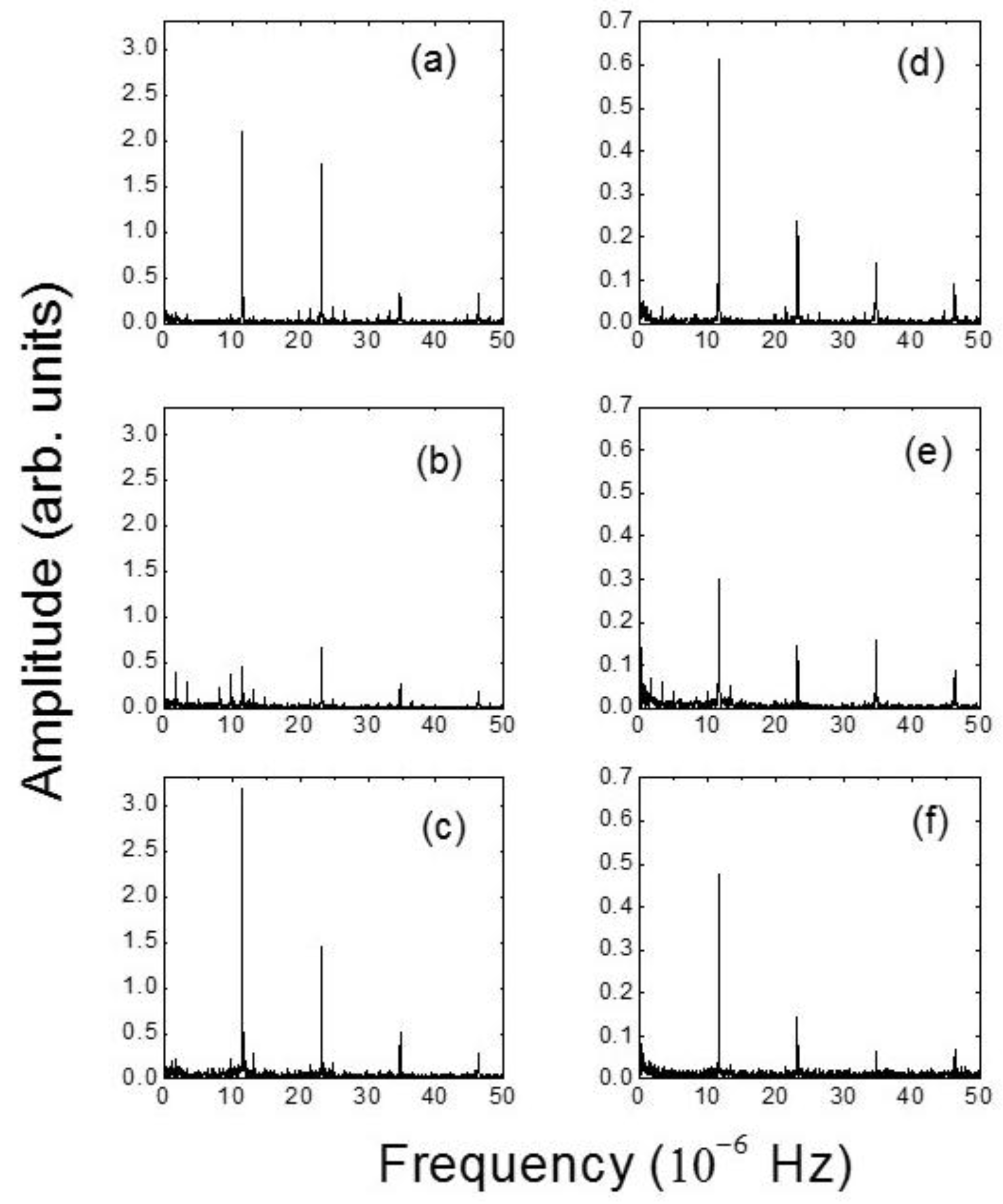
The frequencies extracted from the time-frequency domain are 11.55 × 10
−6 Hz, 23.10 × 10
−6 Hz, 34.70 × 10
−6 Hz for the three lines. Looking at
Figure 3 the two FFT frequencies corresponding to the harmonics H
1 and H
2 (24 h and 12 h, respectively) are found also according to the WT-based method both for active and reactive powers for lines L
1 and L
3, while for line L
2 only the one corresponding to 12 h was computed. Instead, the frequencies corresponding to the H
3 and H
4 harmonics (8 h and 6 h, respectively) lack in the WT analysis for the line L
3, but the frequency corresponding to H
3 compares well to the one found with WT analysis in lines L
1 (small value) and L
2. These results suggest that the non-stationary behavior included within the WT analysis does not lead to essential changes of the frequencies corresponding to the main H
1 and H
2 harmonics. On the other hand, a limited additional frequency present in the FFT spectra for the line L
2 corresponding to a week’s activity was also found.
Nevertheless, despite its solid basis, the above preliminary analysis performed according to the FFT and to the WT techniques does not allow the full characterization of the different lines―for instance, in terms of their non-linear behavior that is in turn strictly connected with the deviation from periodicity for an electrical power signal. For this reason, as a first further step the HHT analysis combined with the EMD has been applied to the three lines and the obtained results have been compared to the ones derived by means of the FFT and WT analysis. However, since the HHT-EMD tool did not completely quantitatively characterize the features of the power signal, the new suggested indices introduced in
Section 2 have been computed. Note that the calculation of the three indices expressed in Equations (4)–(6) is the main step of our investigation.
4.3. HHT-EMD Results Compared to FFT and Wavelet Results: Calculation of Frequencies of IMFs
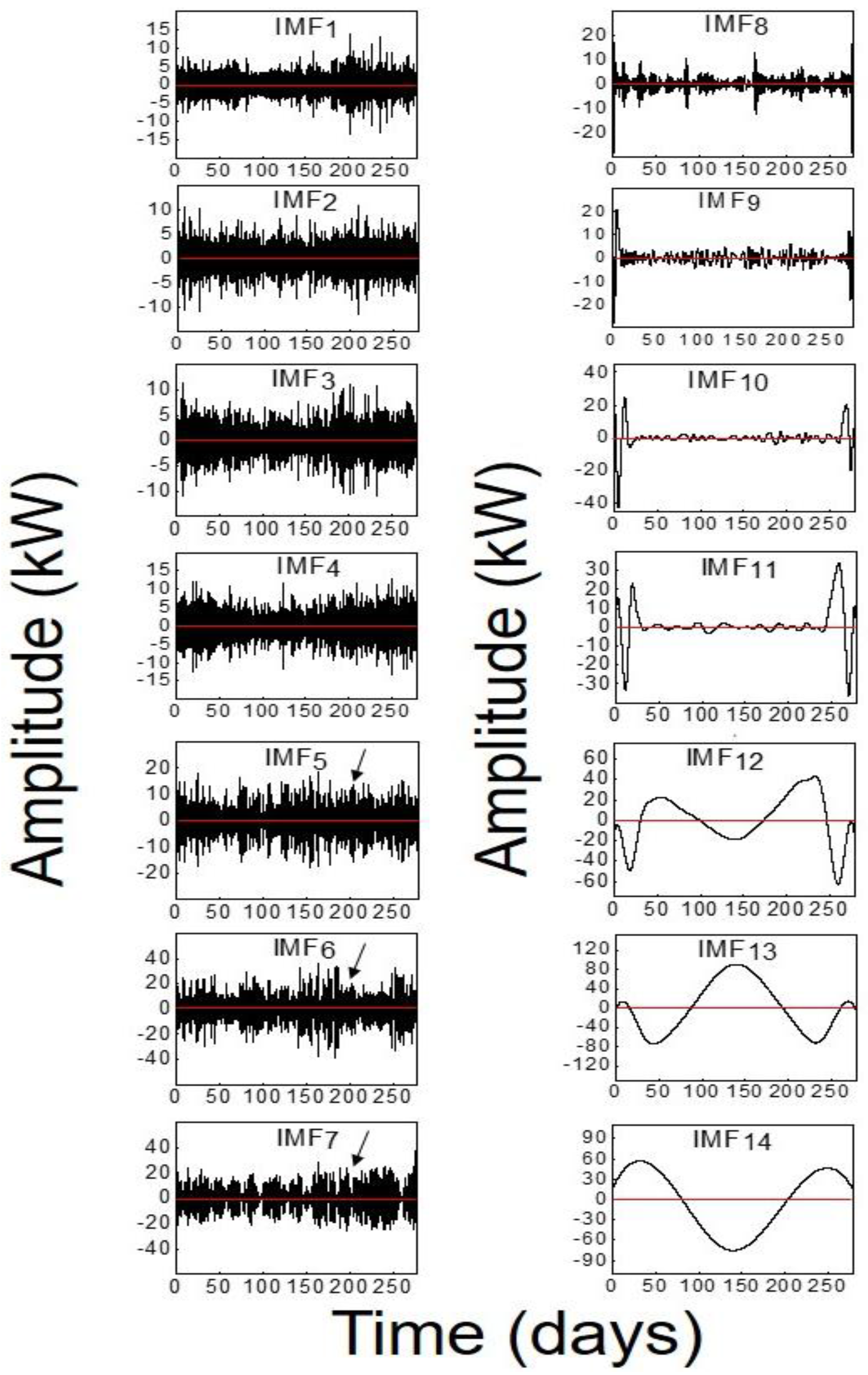
According to the EMD analysis based on the HHT technique, the electrical signal is decomposed into 14 IMFs for both the active and the reactive powers of the three lines. As an example,
Figure 4 shows the time behavior of the 14 IMFs of the P
3 active power for the whole sampling period, labeled as IMF
i with
I = 1, 2, … 14 in decreasing frequency order. The corresponding amplitudes of the IMFs related to the other active powers and reactive powers have a similar trend.
Looking at
Figure 4, the number of oscillations of the IMFs decreases as the IMF order increases. This depends on the procedure used for the iterative extractions of each IMF. In fact, each step of EMD provides a new signal equal to the subtraction between the original one and the mean value of the envelope curves of its local maximum and minimum values. At the end of the process, it retains only the residual non-oscillatory term
rN (not shown).
Looking at the amplitudes of the IMFs it can be seen that there are no changes in the oscillation frequency, confirming that for each IMF amplitude there are no superpositions of different monocomponents. The IMFs 5–7 (denoted with arrows in
Figure 4) have frequencies comparable to those corresponding to the FFT harmonics and also to some of the WT frequencies. The amplitudes averaged over the whole period have zero mean values, as should be expected.
The frequencies of the IMFs according to the average procedure described below are summarized in
Table 1. As a general remark, it is evident that there is a greater number of frequencies calculated via the HHT-EMD than the ones determined by means of the FFT and WT analysis. This is not surprising because it is strictly connected mainly to the non-periodical behavior of the power signals in all the lines with different degrees of deviation from periodicity (see
Section 4 for details) and to a lesser extent also to the non-stationary behavior. The deviation from a purely periodical behavior is in turn related to the non-linear behavior of power signals in DLs of SGs. In particular, the HHT approach combined with the EMD procedure allows the extraction of additional modes compared to the FFT.
Finally, just as EMD is based on the envelope curves of local maximum and minimum values, IMFs with lower frequencies can be extracted before IMFs with higher frequencies. For example, looking at the first row of
Table 1 for P
1, it can be observed that IMF
10 has 0.08 × 10
−6 Hz, whereas the IMF
11 and IMF
12 have higher frequencies, equal to 0.13 × 10
−6 Hz and 0.12 × 10
−6 Hz, respectively. Note that the frequencies shown in
Table 1 are not properly the instantaneous frequencies expressed in Equation (3) that by definition depend on time as is typically shown in the so-called Hilbert spectrum. As a matter of fact, in order to compare the obtained frequencies with the corresponding ones computed via FFT and WT techniques, we have performed an average of the instantaneous IMF frequencies over the total sampling period. This procedure recalls the one employed for the calculation of the Hilbert average marginal spectrum obtained from the Hilbert spectrum by integrating it over the total sampling period and by dividing the result of this integration by the total sampling period. Of course, this analogy is no longer valid when the instantaneous frequency of the tone does not oscillate in a very narrow band so there could be points assigned to a different frequency in the Hilbert marginal spectrum. However, we would also like to stress that the Hilbert marginal spectrum has relevant meaning in the analysis of the HHT frequencies, is strictly connected to the HHT analysis and also used for extracting the general features of an electrical power signal. The advantage of this procedure is that it is possible to directly compare these mean single frequency values with the ones obtained with the other two techniques described above. On the other hand, this approach does not change the discussion since we have found that the instantaneous IMF frequencies extracted from the EMD technique do not appreciably vary with time despite the daily variations of loads in the different power lines. The weak variation as a function of time also characterizes the frequencies calculated by means of the WT analysis (see
Figure 3).
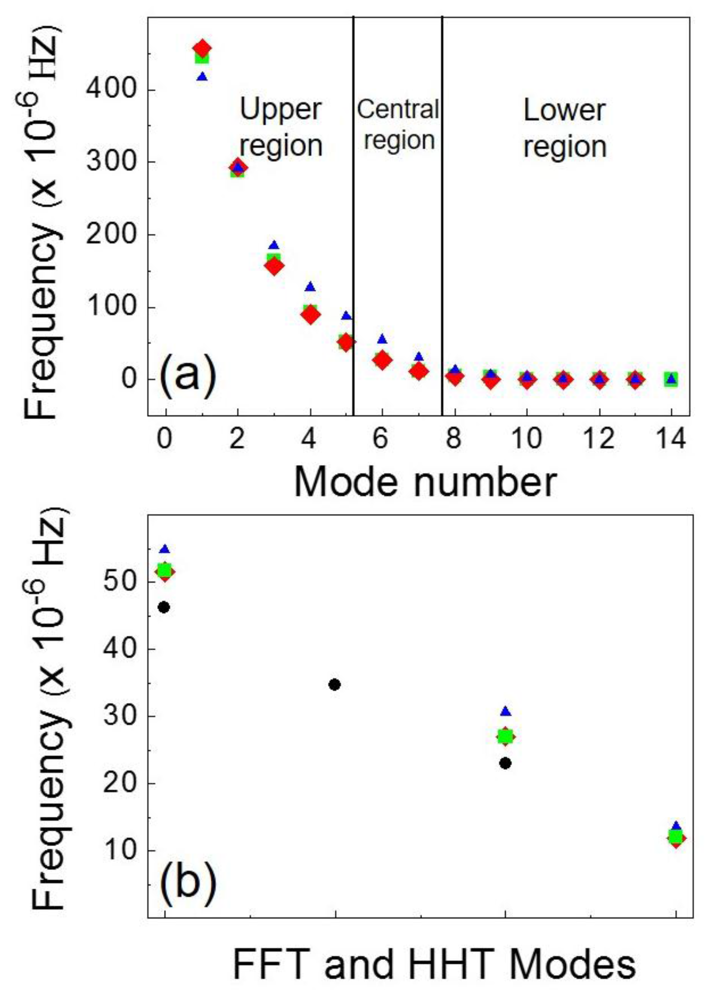
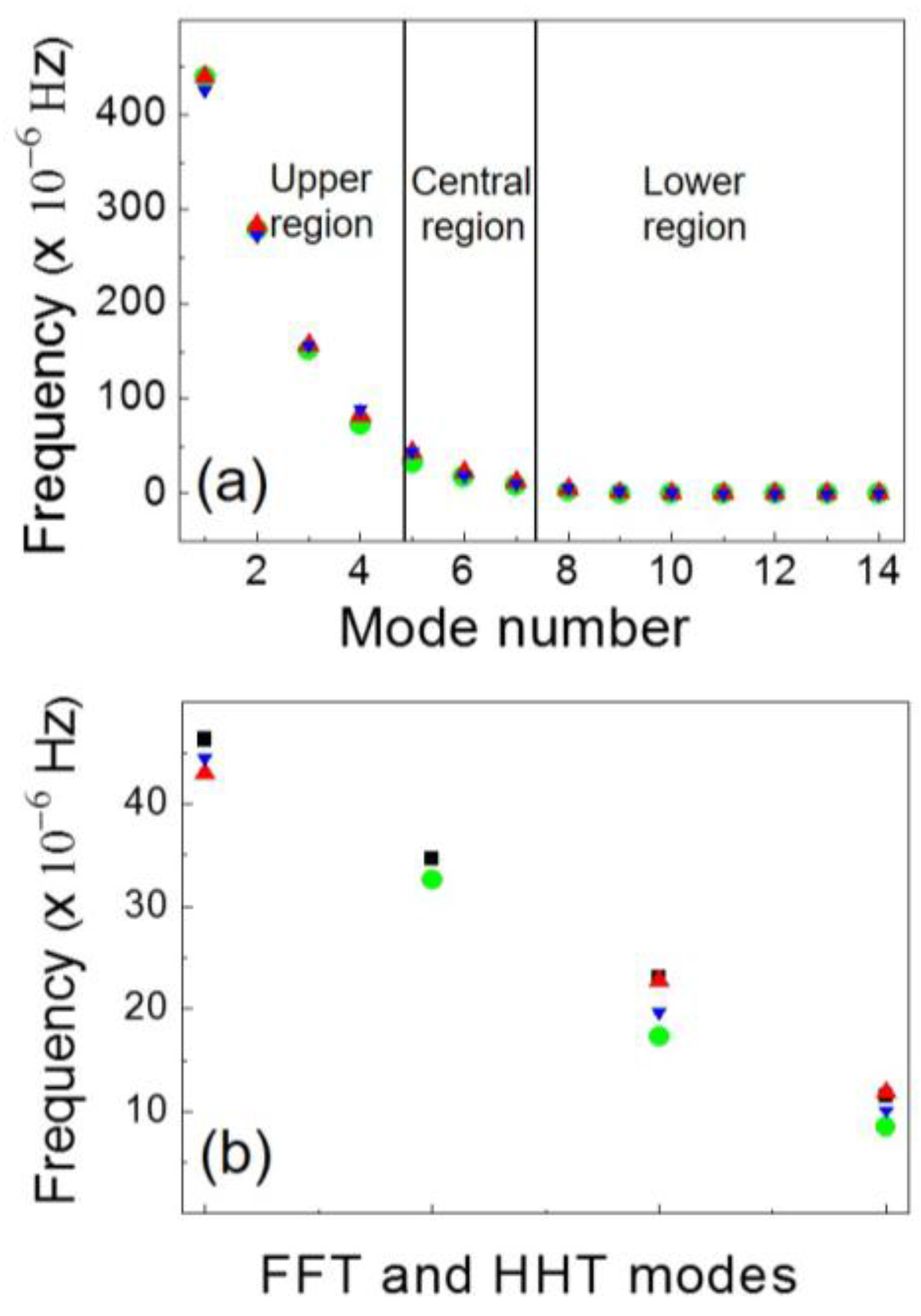
In order to clarify better the following discussion, we distinguish for every line three different frequency regions of the spectrum. In
Figure 5a, the three frequency regions are shown by plotting the frequencies of the IMFs related to the three active powers. In addition to the central region, covering the frequency range of the typical harmonics found in the FFT spectrum, there are other two regions, the upper and the lower one. The lower region includes low frequencies with values up to about 5 × 10
−6 Hz and, apart from one exception, the found frequencies are not present in the FFT spectrum. The central region has frequencies included in the range between about 10 × 10
−6 Hz and about 50 × 10
−6 Hz and corresponds more or less to the ones of the FFT spectrum. In the upper region there are frequencies having values above 50 × 10
−6 Hz up to approximately 450 × 10
−6 Hz; these frequencies are not present in the FFT spectrum. This wide range of frequencies computed via the HHT calculation is the combined result of the deviation from a purely periodical behavior, in turn strictly related to non-linearity effects that cannot be taken into account by the FFT analysis. For a detailed quantitative discussion on this point see next
Section 4, where the calculated indices presented in
Section 2 are discussed.
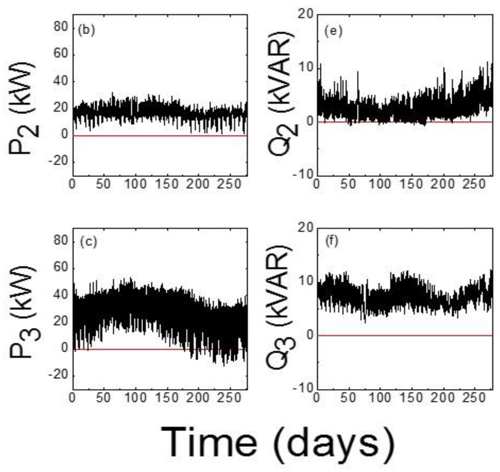
We now quantitatively discuss the frequencies related to the active powers. For the L
1 passive line and the L
3 active line the HHT frequencies differ appreciably especially in the upper and central regions (see also
Table 1). This different trend is not surprising because of the strong difference in PV plants feeding the two lines which leads to different values of the active powers with P
3 assuming also negative values (see
Figure 1c). Moreover, frequencies referred to the active powers of the L
2 passive line have overall different values with respect to those of P
1 and P
3.
More specifically, it is useful to make a quantitative comparison among the frequencies belonging to the central region with the corresponding frequencies of the typical FFT harmonics for P
1, P
2 and P
3 active powers. The comparison between the HHT-EMD frequencies and the FFT harmonics is illustrated in
Figure 5b. For the first passive line L
1, the two first most representative frequencies 8.50 and 17.28 × 10
−6 Hz (green circles) strongly differ from the frequencies of the H
1 (11.50 × 10
−6 Hz) and H
2 (23.10 × 10
−6 Hz) harmonics, respectively determined via the FFT (black squares), while the third one at 32.65 × 10
−6 Hz has a much closer value to the frequency (34.70 × 10
−6 Hz) of the H
3 harmonic.
On the other hand, there is no trace of the one corresponding to the 6 h peak as found according to the FFT. By contrast, the HHT-EMD frequencies corresponding to those of the H1, H2 and H4 (46.30 × 10⁻⁶ Hz) harmonics for the second passive line L2 (red up triangles) are rather close to the FFT ones, while the frequency related to the H3 harmonic is not present in the HHT calculation. The frequencies obtained for the L3 active line are slightly different with respect to the FFT ones especially those corresponding to the H1 and H2 harmonics (blue down triangles). Also for the L3 active line there is the lack of the mode corresponding to the frequency of the H3 harmonic and a frequency at 88.64 × 10⁻⁶ Hz not found according to the FFT calculation (it would be the equivalent of the frequency of the H5 harmonic). This frequency corresponds to 3 h. The same conclusions can be drawn if the HHT-EMD frequencies are compared to the WT frequencies, which are superimposable to the ones of the FFT. Special attention deserves also the analysis of other characteristic frequencies belonging to the IMFs in the lower region of the spectrum. In particular, in addition to several frequencies not present in the FFT spectrum, the HHT analysis also confirms, for the L2 passive line, the frequency (1.29 × 10⁻⁶ Hz) corresponding to 1 week found via the FFT analysis, which is typical of commercial loads. Concerning the frequencies of the IMFs above 50 × 10−6 Hz in the upper region, these would correspond approximately for every line to 2 h, 1 h and about ½ h, respectively. The above-mentioned additional features typical of the HHT spectrum and related to a combination of non-linear effects, deviation from a periodical behavior and non-stationary behavior were not extracted from the FFT and WT analysis.
To check further the findings obtained for the P(
t) signal we have processed the same datasets for the corresponding reactive powers Q(
t) illustrated in
Table 1 where the Q
2 reactive power has 13 IMFs frequencies and the Q
3 has 4 additional IMFs in the lower frequency region (not shown). The frequencies of the IMFs are also plotted in
Figure 6a for Q(
t) and subdivided into the three regions as done in
Figure 5a. In
Figure 6b the FFT frequencies of the main FFT harmonics related to the reactive powers are compared to the HHT corresponding ones in the central region of the spectrum.
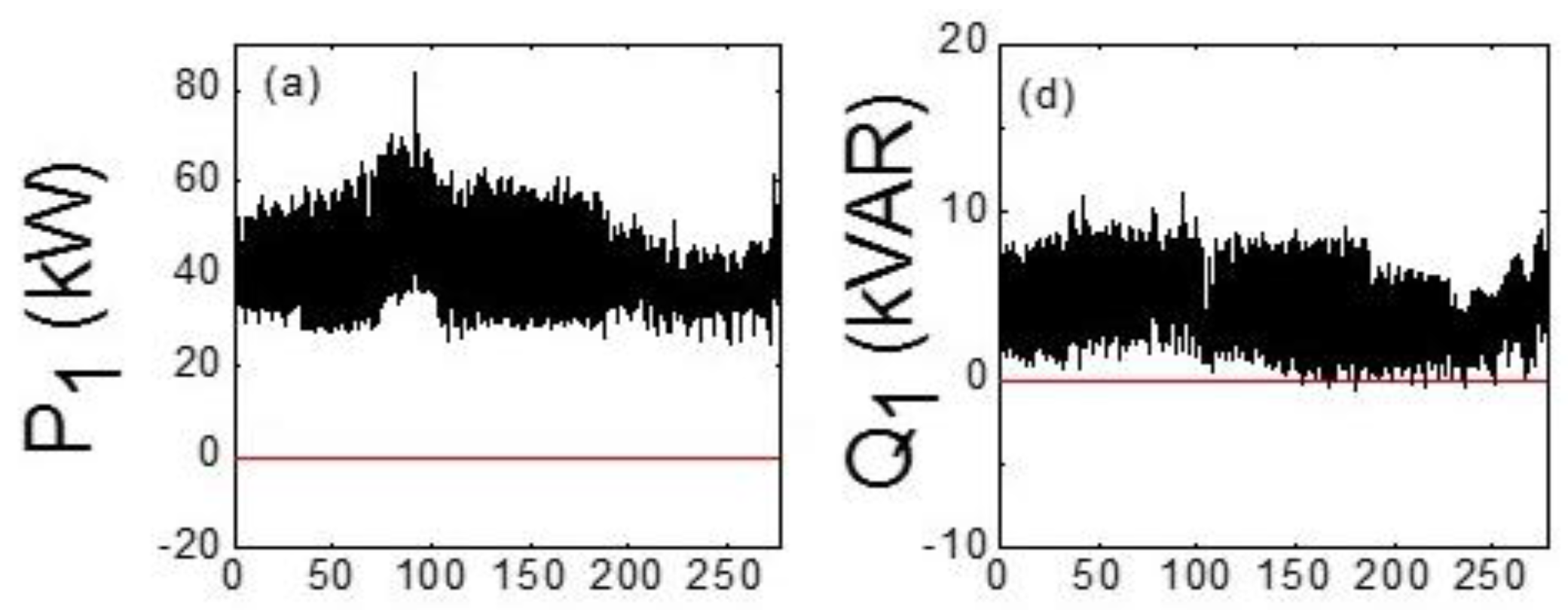
Looking at
Table 1 and
Figure 6a, the frequencies of the IMFs corresponding to the Q
1 and Q
2 reactive powers are rather close each other due to the similar behavior of the signal (see
Figure 1d,e), apart from some discrepancies which result from the difference between PV plants characterizing the L
1 and the L
2 passive lines. Instead, due to the different behavior of Q
3 (see
Figure 1f), most of the calculated frequencies of the IMFs are different with respect to those of L
1 and L
2. Unlike the FFT analysis that gives very similar results, the comparison of the frequencies related to the active and the reactive powers, leads to different results. Indeed, there are significant differences between the frequencies related to the active powers and the corresponding ones associated to the reactive powers especially in the central region of the IMF frequencies. For example, the frequencies corresponding to those of the H
2 and H
3 harmonics typical of the FFT spectra were not found (see
Figure 6b). The frequencies 12.08 × 10
−6 Hz and 11.91 × 10
−6 Hz rather close to that of the H
1 harmonic (11.50 × 10
−6 Hz) were found only for Q
1 and Q
2 belonging to the lines L
1 and L
2, respectively but not for Q
3 belonging to the line L
3. Even though the HHT calculated frequencies 51.55 × 10
−6 Hz, 51.72 × 10
−6 Hz and 54.83 × 10
−6 Hz for Q
1, Q
2 and Q
3 are higher than the frequency of the typical FFT H
4 harmonic (46.30 × 10
−6 Hz), they can be considered their corresponding HHT frequencies. The found discrepancies can be ascribed to the more accurate analysis given by HHT.
In fact, the HHT computation is able to highlight the local properties of a typical power signal related to the effects of non-linearity that in turn give rise to its not-fully periodical character. In this respect, we believe that the deviation from periodicity of the power signal (for a quantitative analysis see
Section 4) could lead to the lack of some of the frequencies in the HHT spectrum and especially the ones corresponding to the higher FFT harmonics.
We also performed an analysis of the data for single year’s quarters based on the HHT and some results are different (here not shown). For more details about this seasonal analysis see [
34].
4.4. The Indices: Numerical Evaluation
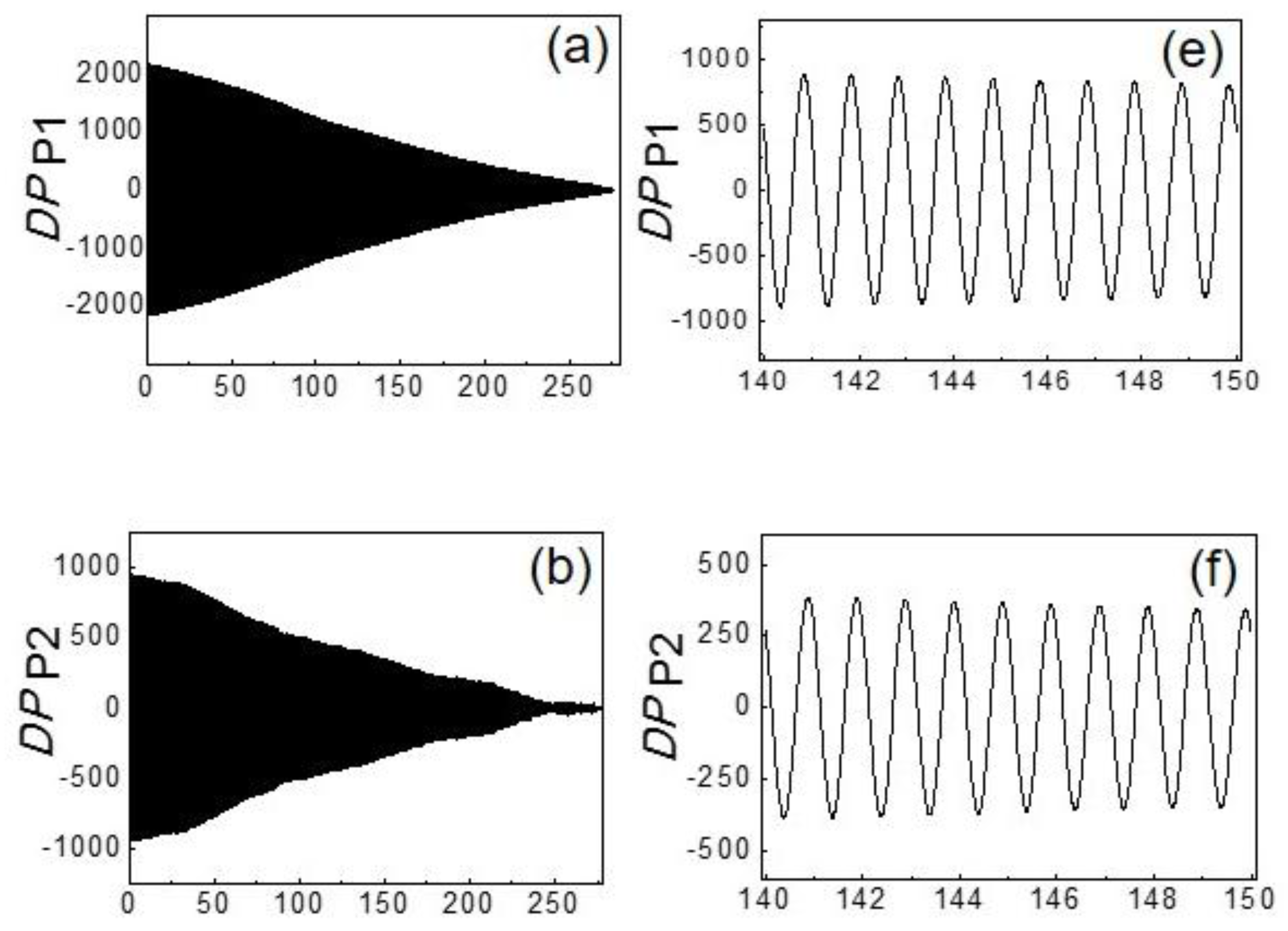
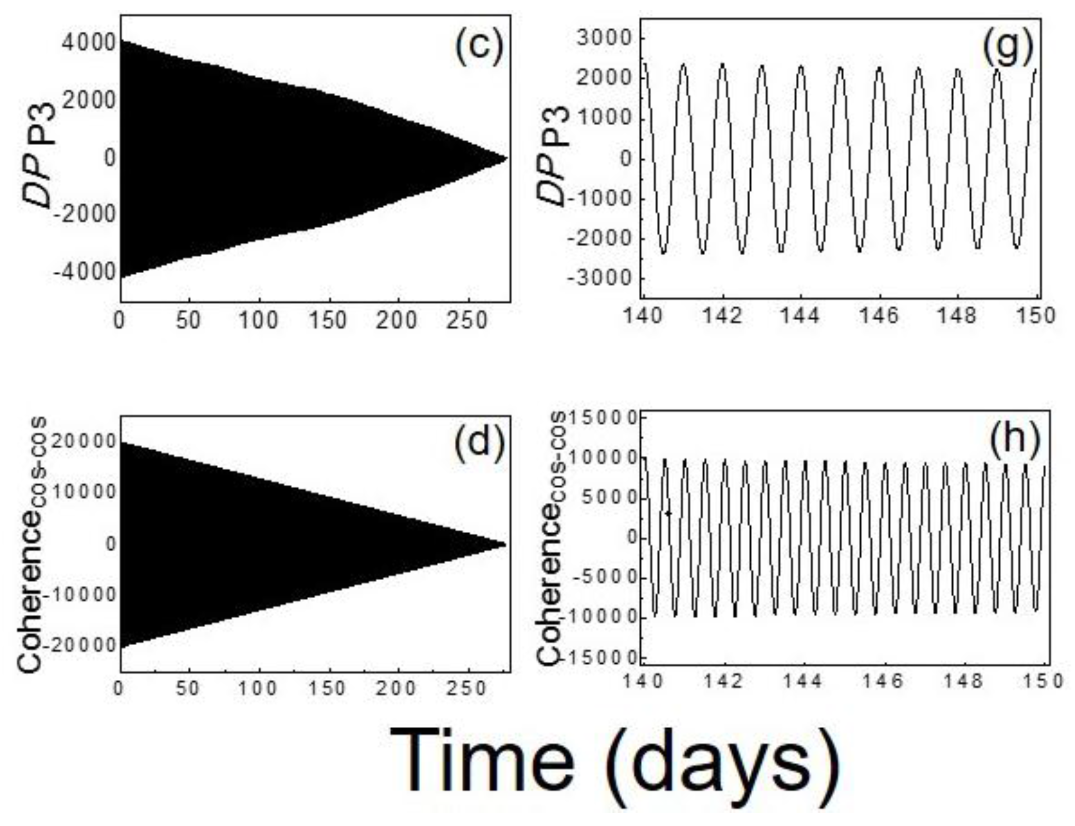
In this subsection, the results of the numerical computation of the indices expressed by Equations (4)–(6) are presented. In
Figure 7 the
DP index defined in Equation (4) and calculated for the P
1, P
2 and P
3 active powers is displayed, both for the total sampling period of 278 days in panels (a)–(c). In addition, a zoom of the signal for a temporal window ranging between the 140th and the 150th day (approximately located in the middle) is reported in panels (e)–(g) of
Figure 6. As a reference, the coherence degree
as a function of time is displayed for a couple of cosine functions (see panel (d) and (h)). As expected, according to the definition of time-correlation functions [
38], the general behavior is the decrease of the DP index amplitude with increasing time as illustrated in panels (a)–(d) marking a general reduction of the correlation of a given power signal with a cosine (or sine) function. From the analysis of the oscillation amplitudes, it turns out that the strongest deviation from the purely periodical behavior that is typical of a cosine (or sine) function having indeed the highest coherence degree characterizes the P
2 active power. This can be inferred by looking at the maximum oscillation amplitude of
DP which for the P
2 active power is less pronounced (panel (f)) with respect to the ones involving the P
1 and P
3 active powers (panels (e) and (g)). In particular, in the shown temporal window of 10 days, the amplitude variation is about 750 for
, about 1700 for
and more than 4000 for
. The oscillation amplitudes of
and
are much closer to the one characterizing the Coherence
cos-cos (panel (h)) between two cosine functions thus marking their higher periodicity degree. This behavior is very similar also by focusing on other temporal windows. The conclusions drawn for the
DP index computed for the active powers remain valid also for the corresponding reactive powers. Therefore, the quantitative analysis on the
DP index indicates that the L
1 passive line and the L
3 active line are characterized by a signal deviating to a lesser extent from the purely periodical behavior. First, from an overall analysis looking at
Figure 7 it is important to note that the periodicity degree of the power signal does not strictly depend on the injected PV power, but it is strongly related to the loads and to the operating conditions. In particular, in this study we observe that the lines characterized by power signals with a smaller deviation from a purely periodical behavior are the ones feeding residential users, namely the L
1 passive line and the L
3 active line, one with no PV power and the other with a high PV power. However, from a more specific and deeper analysis it can be seen, by comparing panels (e), (g) and (h) of
Figure 7, that the L
3 active line having the largest injected PV power is the one with the smaller deviation from a purely periodical behavior because it is characterized by the largest oscillation amplitudes. Therefore, the computation of the
DP index could be helpful for highlighting the future advantages of planning lines having a high percentage of PV plants. Indeed, we can conclude that the more the concentration of PV plants is higher, the more the power signals tends towards periodical behavior, and this is potentially advantageous for the future operating conditions in DLs of SGs.
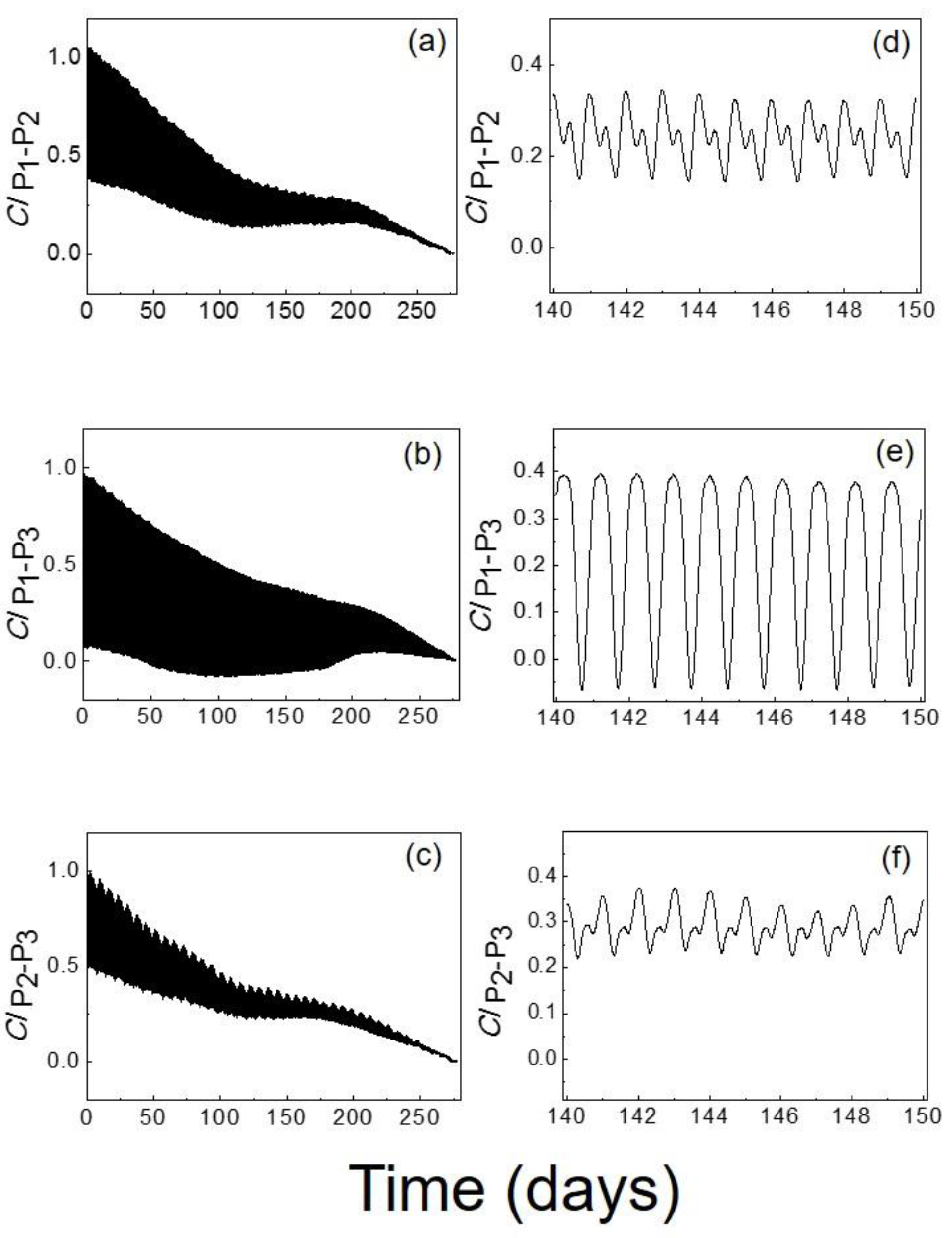
In
Figure 8 the
CI between a given couple of active powers defined in Equation (5) is shown in normalized units. According to its definition, resulting from the time-correlation function and similarly to the
DP index also the amplitude of the
CI reduces with increasing time. In panels (d)–(f) of
Figure 7 the
CI is shown in a temporal window ranging between the 140th and the 150th day. It can be noted that the
CI trend as a function of time is strongly altered with an important amplitude reduction when the coherence is computed between the P
1 and P
2 and between the P
2 and P
3 active powers. Moreover, in this case there is also a reduced
CI amplitude. Instead,
exhibits regular oscillations marking a stronger coherence between the P
1 and P
3 active powers. The
CI for the reactive powers shows very similar behavior with respect to that of the active powers, as occurred for the
DP index. This can be understood by taking into account that the L
1 and L
3 lines feed residential users, while the L
2 line feeds commercial users. By means of this analysis we are able to quantify the coherence degree of two given power lines in different temporal windows and this can be done for any given available power line. As expected, the coherence degree resulting from the two residential lines, one active and the other passive, is higher than that computed between a residential line and a commercial line (one active and one passive or two passive lines).
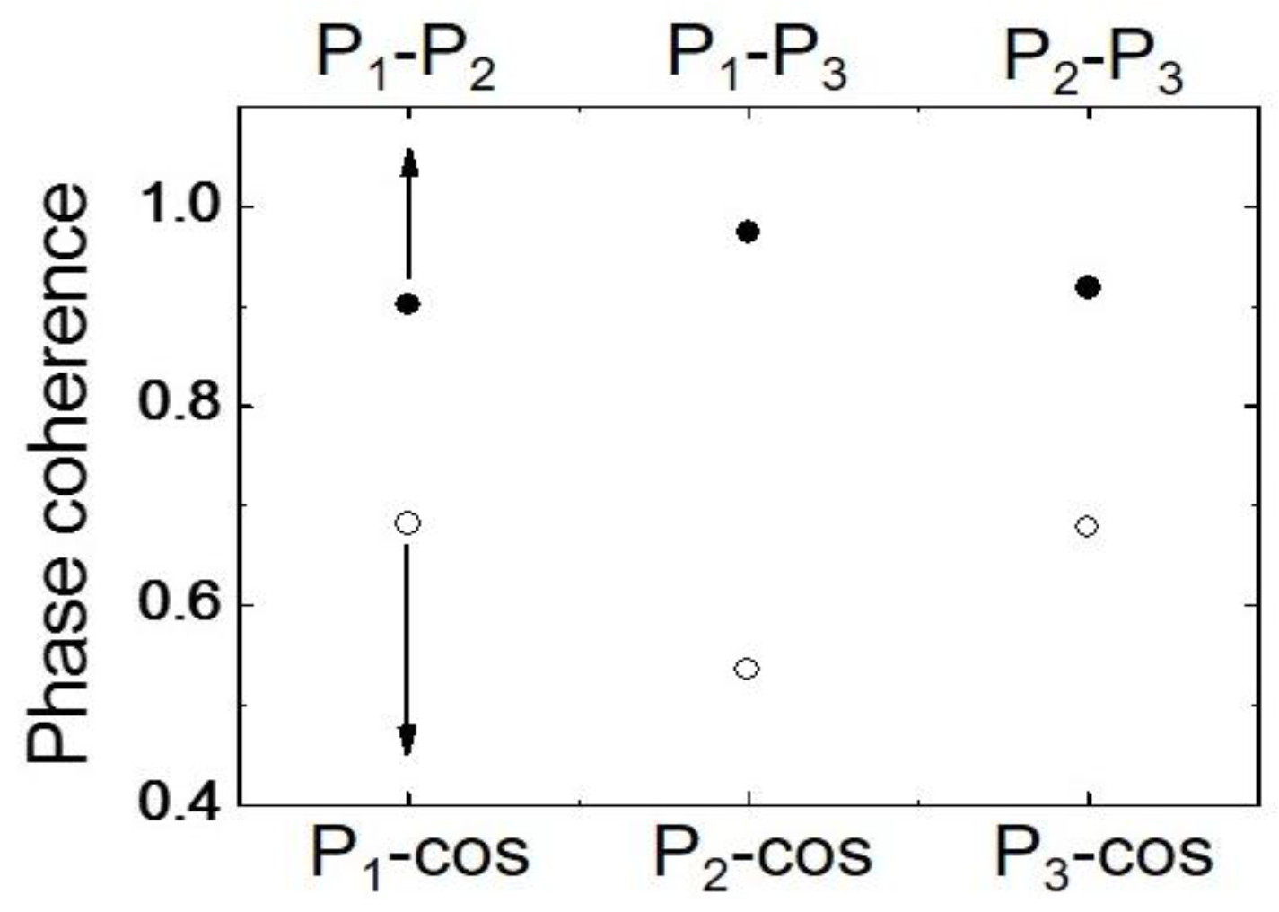
In order to validate the previous results the
PC defined in Equation (6) has also been calculated. The results of this calculation are displayed in
Figure 9. The phase coherence between the P
1, P
2 and P
3 active powers and the cosine function (empty circles) is higher for the two residential lines, being about 0.68 for P
1-cos and P
3-cos, while the one related to the commercial line (P
2-cos) is about 0.54.
These results show that the phase coherence with a co-sinusoidal (or sinusoidal) electrical signal is higher for the residential lines confirming the previous predictions. Moreover, the phase coherence between P1 and P3 (full circles) is equal to 0.97, while the ones between P1 and P2 and P2 and P3 active powers are about 0.90. According to this analysis, it can be established the PC for each given line and it is confirmed that the degree of phase coherence is higher between the two residential lines. Therefore, this index is useful to characterize the type of users of the line and it is not influenced by the quantity of installed PV power.


