1. Introduction
Despite advances in PV systems such as reduction in cost and improved cell efficiency, low energy conversion efficiency remains a significant barrier to widespread utilization. Additionally the amount of energy generated depends significantly on environmental factors such as ambient temperature and solar irradiance. Given this, in order to achieve the maximum power from the output of the PV array the control unit needs to have an appropriate strategy for maximum power point tracking (MPPT) so as to be able to provide the appropriate duty cycle to the DC-DC converter. Considering the costs associated with different aspects of a PV system such as material efficiency, integration and structural configuration, improving MPPT capability is the most economical way to improve the efficiency of the PV system.
PV systems often comprise many PV modules connected in series and/or parallel to achieve the required output voltage and current. Because of this, when some of the modules of a PV system receive lower solar irradiance due to occlusion of the sun by objects such as clouds, trees and buildings, a condition known as partial shading, the output of the PV system is affected. The impact to the output power depends on factors such as shading scheme, system architecture, or even the number of integrated bypass diodes. A common approach to increase efficiency of PV arrays subject to partial shading is to include bypass diodes, however this can result in multi-peak voltage-power characteristics. In this situation most of the conventional MPPT methods will detect the local maximum power point (MPP) rather than the global MPP. Herein, local MPP refers to a point in which the power is maximum for a portion of the search space, while global MPP represents a point that the power is greater than all points for the whole search space.
A number of studies have investigated GMPP tracking strategies subject to non-uniform irradiance levels [
1,
2,
3,
4,
5,
6,
7,
8,
9,
10,
11,
12,
13,
14,
15,
16,
17,
18,
19,
20]. The work [
13] discusses a two-stage approach for GMPP tracking. The first stage of the approach recognizes the neighboring areas of the MPP, and the second tracks the actual GMPP. This method is not however able to track the actual GMPP for all partial shading conditions, such as when the load intersecting the output curve lies on the right hand side of the GMPP. In [
12] a new approach for MPPT which works subject partial shading conditions is introduced. The method depends on the voltage values for each MPP being previously evaluated and therefore is system dependent. In [
11,
16] the authors proposed a Fibonacci sequence-based approach to tracking the GMPP. In a manner similar to perturbation and observation (P&O), the measured power of two points is used to determine movement to the next operating point. The difference with the P&O method is that the Fibonacci sequence is used to determine the step size resulting in improved tracking speed. Despite this however, the drawback of the conventional P&O method still remains where GMPP tracking is not guaranteed for all partial shading conditions.
Another two-staged approach to finding the actual GMPP is proposed in [
3]. All of the local MPPs are monitored in the first stage and then in the second stage the GMPP is tracked using the P&O method. Although the method has relatively high efficiency, for some partial shading conditions the algorithm needs to scan almost all ranges of the search space resulting in a slow process. Another two-stage approach uses the dividing rectangle search method to find the region of the GMPP. Once the region is found, i.e., the condition for stopping is met, the GMPP is found using P&O. The results prove the reliability of the approach for certain partial shading conditions. The method is however complex and considerably increases the computational burden. The extremum seeking control approach is introduced in [
10] and uses the segmental search concept for modelling the PV array characteristic in the tracking process. The approach was evaluated for different partial shading conditions and found to be quite efficient however is system-dependent and produces initial steady-state errors.
Soft computing techniques, such as artificial neural networks (ANNs) and fuzzy logic control (FLC) have been popular among researchers [
21,
22,
23,
24]. In [
24] the authors proposed reliable and efficient fuzzy logic control for tracking the MPP under partial shading conditions. In [
21] FLC is used to improve the performance of the Hill climbing method, through scanning and storing the MPP during the P&O procedures. FLC combined with an ANN is employed in [
22], to track the GMPP where the cell temperature and irradiance level are used to train the ANN for finding the MPP. The above mentioned approaches are able to achieve satisfactory performance for finding the GMPP under normal and certain partial shading conditions however are computationally heavy in the fuzzification, rule base, and defuzzification processes.
Evolution-based methods, such as genetic algorithms, ant colony, differential evolution, and particle swarm optimization (PSO), have been employed to find the best fitness for the MPP objective function, as presented in [
25,
26,
27,
28,
29,
30,
31,
32]. Owing to its capability for stochastic objective functions, the PSO technique has been used prevalently in the literature. For example, in [
25,
26], the authors employed the standard PSO technique to track the global MPP at the output of the partially shaded PV system. The reliability of this technique under partial shading conditions was verified in these studies. However, these techniques involved certain drawbacks that are associated with the standard PSO method. Among these drawbacks are fixed velocity values, large dependency on random coefficients, relatively slow convergence, and high computational cost, which are due to the use of a microcontroller with large memory to record the particle movements in all previous iterations. Many researchers have attempted to solve these problems in their studies, most of which have successfully modified the performance of the standard PSO to a certain extent. However, these problems have either not been fully addressed or other drawbacks have appeared in the modified versions. For instance, in [
33], the authors used a deterministic PSO method with removed random coefficients to reduce the metaheuristic aspect of these evolutionary algorithms. In other studies [
34,
35,
36], PSO has been combined with other methods in the form of hybrid techniques to boost the accuracy and reduce the effects of random coefficients in the PSO technique. These combinations however resulted in longer processing time or higher complexity.
This paper aims to introduce a new simple and fast evolutionary technique for tracking the global MPP at the output of photovoltaic systems under any partial shading condition. The technique is called radial movement optimization and has been proven highly efficient for global optimization in a continuous search space. Unlike conventional methods, this method is capable of tracking the global MPP under any partial shading condition. The main advantages of this method over other evolutionary methods are efficiency under partial shading conditions, high speed, simplicity, and stability during tracking and steady state periods. Compared with the PSO method which has been extensively presented in the literature, the proposed method is faster, less dependent on random coefficients, and needs less memory for processing. Therefore, a low-cost controller can be used easily. Moreover, unlike modified PSO or hybrid methods, the proposed method is simple, fast, and has less computational burden during the processing time. This paper represents the first time that the RMO method has been used for MPP tracking. The speed, efficiency, and stability of the method is verified in this paper under different partial shading conditions, and the results are compared against those of the PSO technique.
To understand the behavior of PV systems and perceive the severe detrimental effects of partial shading problems, the output characteristics of the PV system under normal and partial shading conditions are summarized in the following section. Then, a brief introduction of the RMO technique is followed by the implementation of the proposed method for MPP tracking. Then, different partial shading conditions, which are used as test bench for evaluating the proposed method, are simulated. Finally, the performance results of the proposed technique are compared with the results of the PSO MPPT for the same the simulated conditions.
2. Characteristics of Photovoltaic Systems
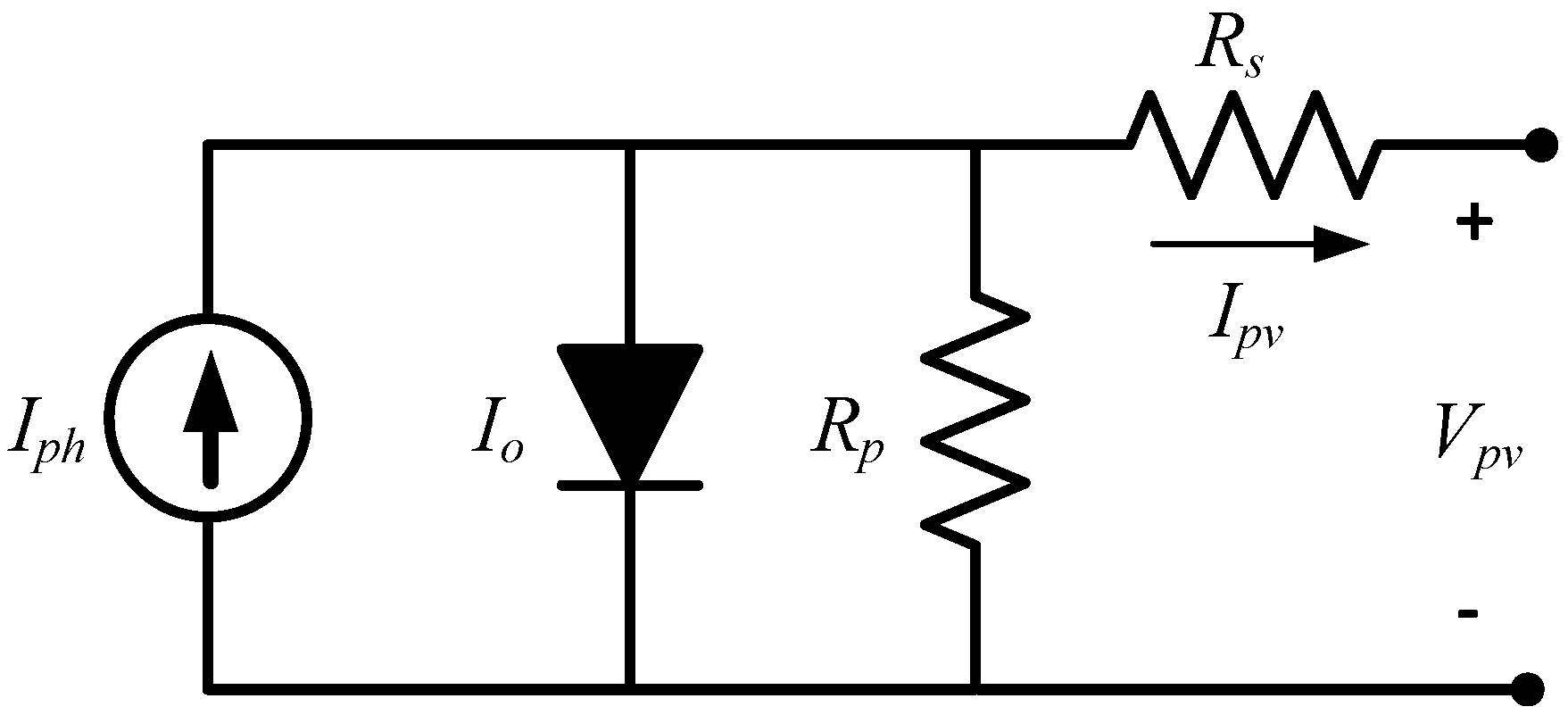
Figure 1 depicts the circuit topology of a typical PV cell. Temperature and solar irradiance directly alter the output characteristics of PV arrays and, as such, to determine the MPP, these values need to be accurately updated. In addition, the PV’s mathematical model varies with the open circuit voltage (
Voc) and short circuit current (
Isc) as obtained from the manufacturer’s data sheet.
Given that the power rating of one solar cell is relatively small and insufficient to provide the required power for majority of applications, these units should be arranged in series or parallel arrangements to form a module where
Ns number of cells all contribute to the output power. The output current of the module can be determined by the following equation:
where
Ipv and
Vpv are the output current and voltage respectively,
Io1 is the diode saturation level,
q has a value of 1.602 × 10
−19 C and represents electron charge constant, A and K are the diode ideality factor and Boltzmann constant respectively,
Tk is the operating temperature which in this paper is considered to be the reference temperature (25 °C), and
Iph is the current generated from solar energy given as follows:
The value of the parallel resistance,
Rp, in Equation (1), is typically very high. In the modeling of the PV module
Rp is sometimes assumed as have negligible impact and of infinite resistance. In contrast,
RS needs to be considered because of its significant to the output power. The electrical parameters of the KC85T PV module are listed in
Table 1.
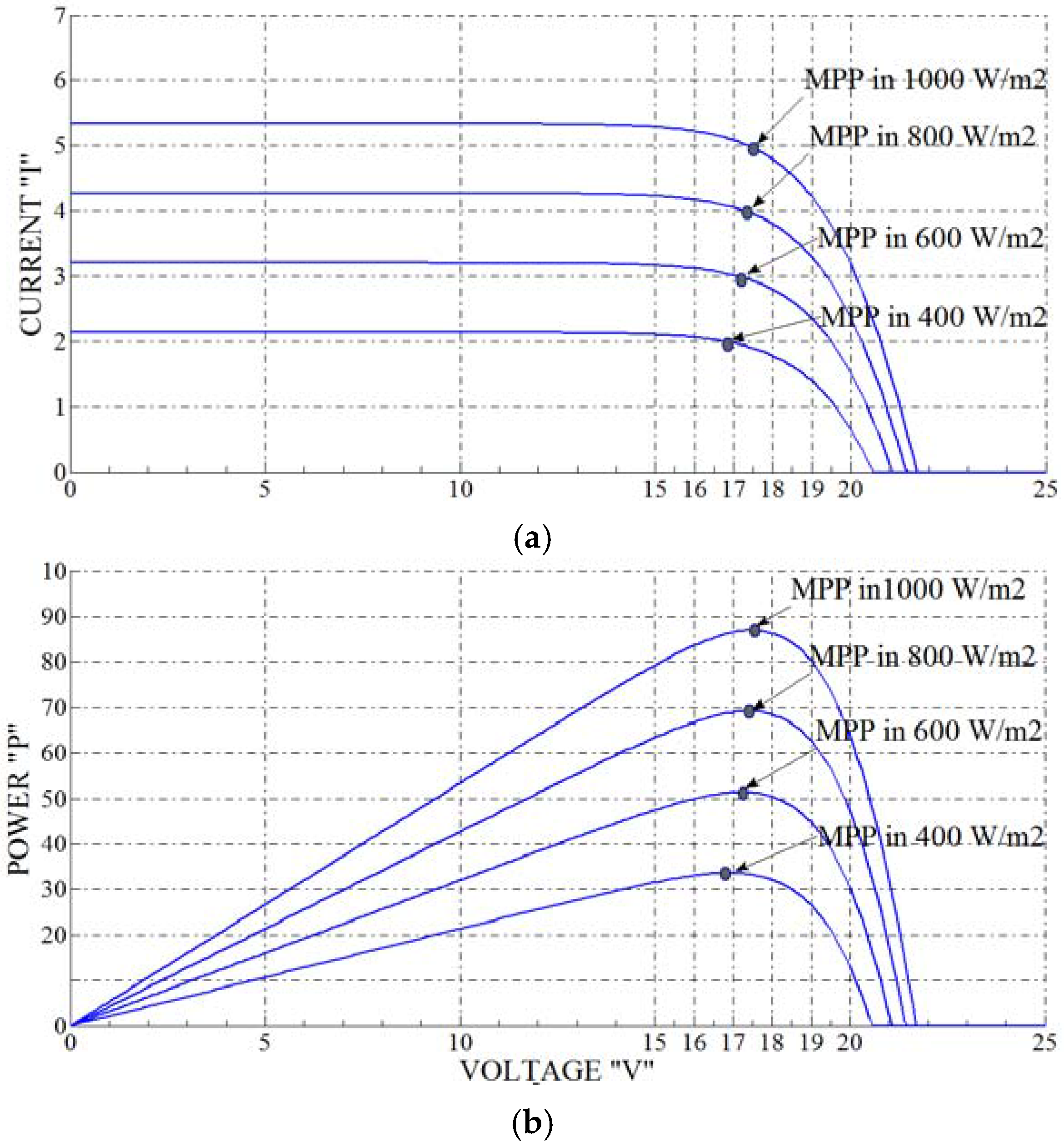
Figure 2 shows the KC85T PV module’s output for varying levels of irradiance.
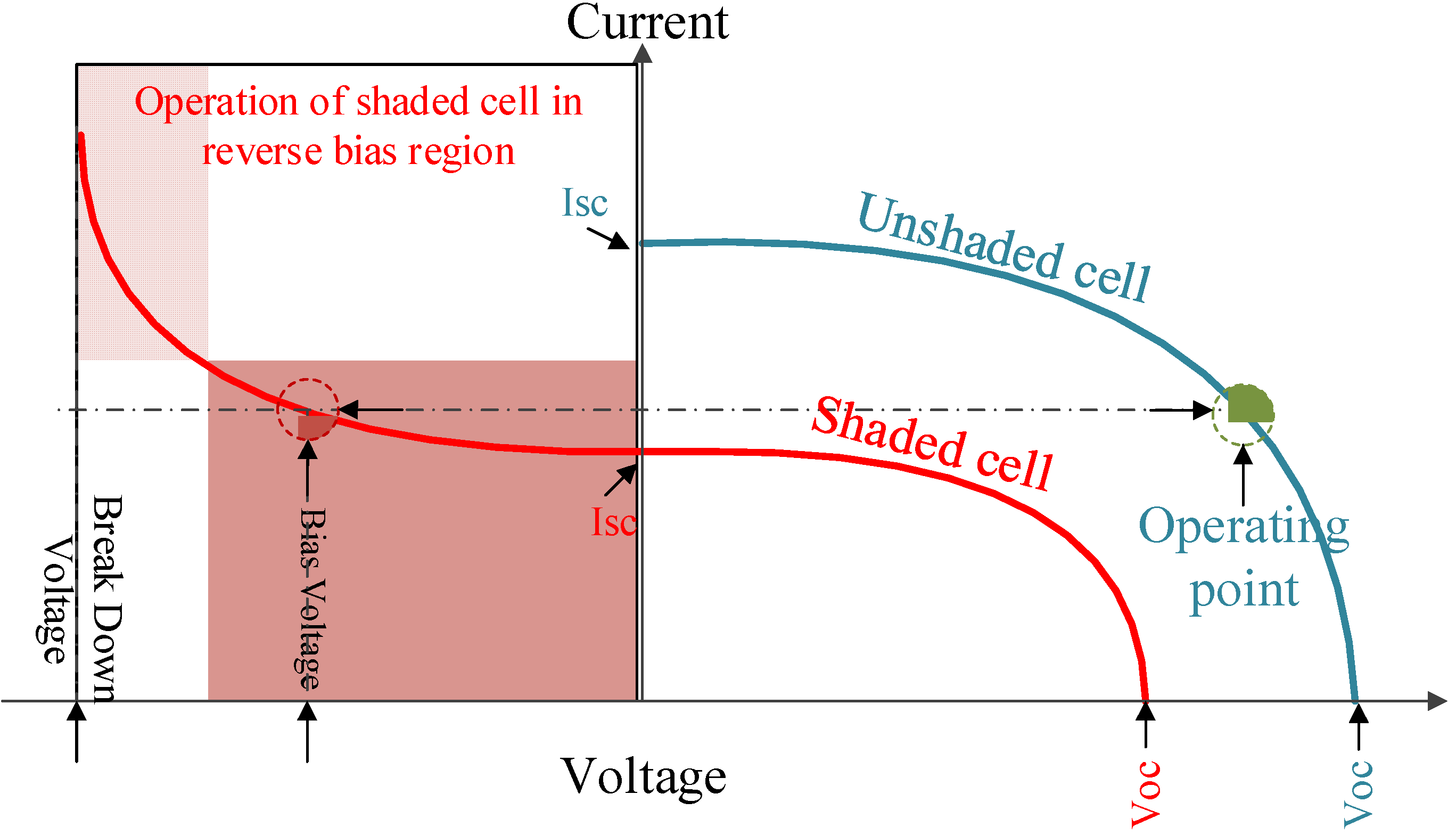
It is possible that outdoor PV systems or part thereof may be subject to non-uniform insolation conditions due to shading by passing clouds and trees. In this situation,
i.e., partial shading, the PV modules receiving similar irradiance will continue operating at optimal efficiency. However, as shown in
Figure 3, due to the series configuration of cell in the module, cells subject to shading, have to operate in the reverse bias voltage region in order to provide the current equal to that flowing in the unshaded cells. Operating in such conditions has an inverse impact on the efficiency of entire module and may cause “hotspots” in solar cells, resulting in an open circuit condition across the whole module. This problem is normally solved through insertion of bypass diodes to a specified number of cells in the series configuration.
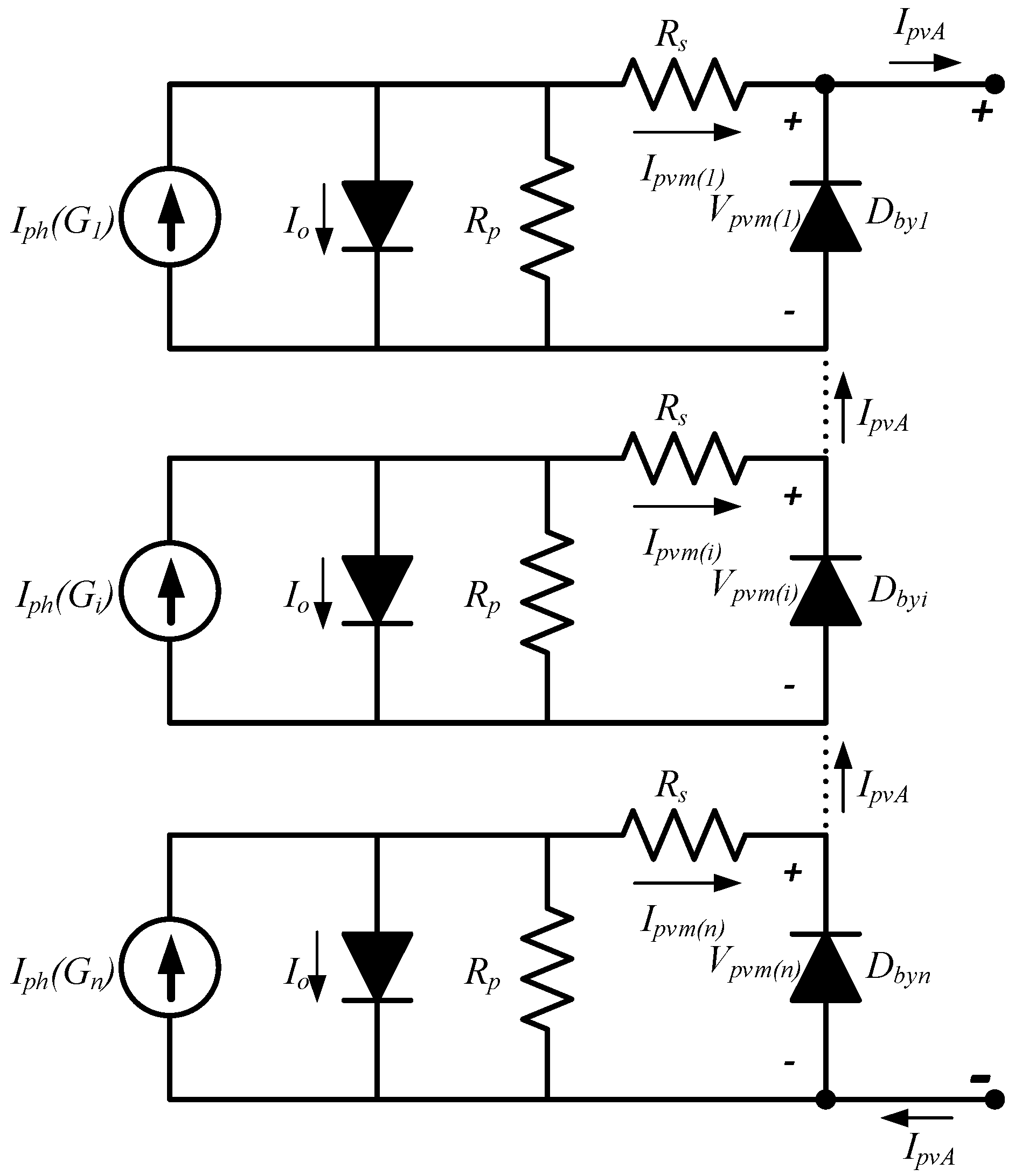
Figure 4 shows the location of bypass diodes in a PV array comprising
k series connected modules. Bypass diodes change the behavior of PV systems under any shading condition. Given the alternate current paths provided by the bypass diodes, when subject to partial shading conditions, the modules do not have the same current values and create multiple maxima at the output of the PV array.
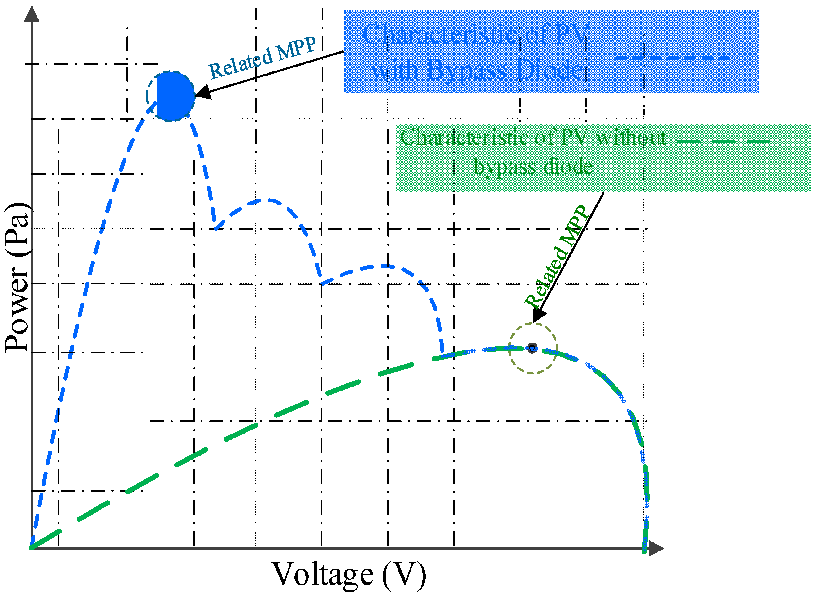
Figure 5 shows how bypass diodes can increase the extractable maximum power at the output of PV arrays. They do however create the multiple maxima at the output of the array. In such conditions, most of the common MPPT techniques are ineffective as they cannot differentiate local and global maxima.
The consequence of partial shading conditions on PV systems has been extensively studied in the recent studies [
37,
38]. The emergence of multiple peaks on the output characteristic curve of PV systems adversely affects the functionality of common MPPT approaches. The main reason for this ineffectiveness is usually that these techniques operate on “hill-climbing” principles, where the next operating point is shifted in the direction where the output power is optimized. These strategies obtain only a local MPP because the P_V curve is multimodal.
5. Results and Discussion
The performance of the proposed MPPT controller based on the RMO method was evaluated under the three different partial shading conditions. Accuracy, speed, reliability, power loss, and oscillation during the tracking period are the main factors monitored in the evaluation and validation processes. It is worth noting that the proposed method is not compared with any of the conventional methods because the method is an evolutionary optimization technique capable of detecting the global candidate solution in the search space. As such, the purpose of this study is to not only evaluate the reliability of this method under partial shading conditions but to also assess the quality of tracking achieved. The results of the proposed method are compared with those of the widely used PSO technique. In order to evaluate the performance of the MPPT method according to the real condition limitations, and to ensure the converter reaches steady state prior to another MPPT cycle beginning, the sampling time of 50 ms was chosen and the parameters of actual PV module of KC85T have been considered in the simulation results.
5.1. Testing Conditions
Since the partial shading condition is a stochastic phenomenon, innumerable conditions and scenarios may occur. However, to evaluate the performance of the proposed algorithm, three different cases with varying degrees of partial shading are represented, covering a range of insolation levels from moderate to acute.
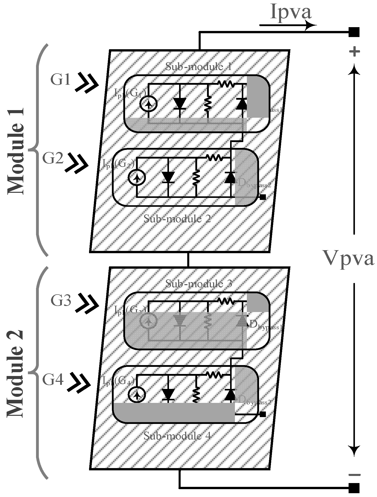
Figure 9 shows the circuit topology of the PV array, including two PV modules.
Given the double-bypass diode in each module, three possible scenarios that have been considered in this study are as follows: (i) the entire module one receives an irradiance level of 1000 W/m2 (G1 = G2 = 1000) and the entire module two receives an irradiance level of 350 W/m2 (G3 = G4 = 350); (ii) the entire module one receives an irradiance level of 1000 W/m2 (G1 = G2 = 1000) and module two receives irradiance levels of 700 W/m2 and 500 W/m2 (G3 = 700, G4 = 500); (iii) module one receives irradiance levels of (G1 = 1200, G2 = 700) and module two receives irradiance levels of 700 W/m2 and 500 W/m2 (G3 = 500, G4 = 300). The RMO technique is applied to all of these conditions to evaluate the quality of tracking, and the results are compared with those of the PSO method.
5.1.1. First Scenario
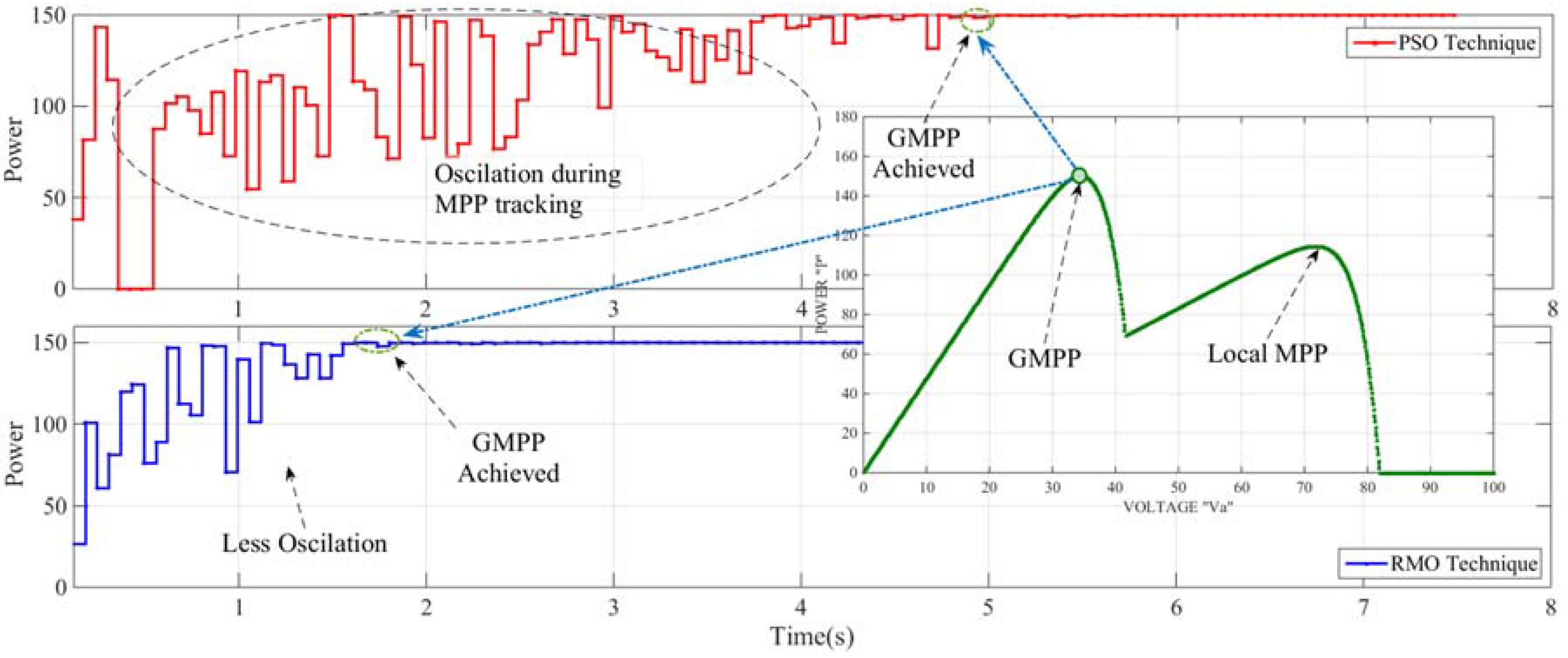
Figure 10 shows the output characteristic of the PV system along with the performance of the proposed method and the PSO method under the first partial shading scenario. The global MPP in this condition can be tracked not only by the soft computing methods but also by the conventional methods that use hill-climbing approach in their tracking system. However, most of these methods suffer from slow convergence time or low efficiency. As shown, the proposed RMO algorithm tracks the actual MPP within around half the tracking time of the PSO algorithm. The trajectory of the power shows that unlike the conventional methods, the tracking process starts from random locations in the search space.
5.1.2. Second Scenario
Further verification of the RMO method is presented in
Figure 11. This condition refers to the second scenario where the output characteristics of the PV system contain three peaks with minor differences among their respective power values. The middle peak’s power value is around 150.5 (W), while the other peaks on the left and right side of the actual GMPP, have the power values of 149.3 (W) and 148.2 (W), respectively. Therefore, this scenario creates a shading condition in which the difference between GMPP and local MPPs is less than 1.5%. The purpose of testing the proposed method under this condition is to check if it is able to track the global MPP while the fitness values of local solutions are very close to the fitness value of the global solution. The figure shows that both the proposed algorithm and PSO accurately tracked the actual MPP at the output of the PV system. The proposed RMO technique however tracked the GMPP in a much shorter time and with fewer oscillations during the tracking period.
5.1.3. Third Scenario
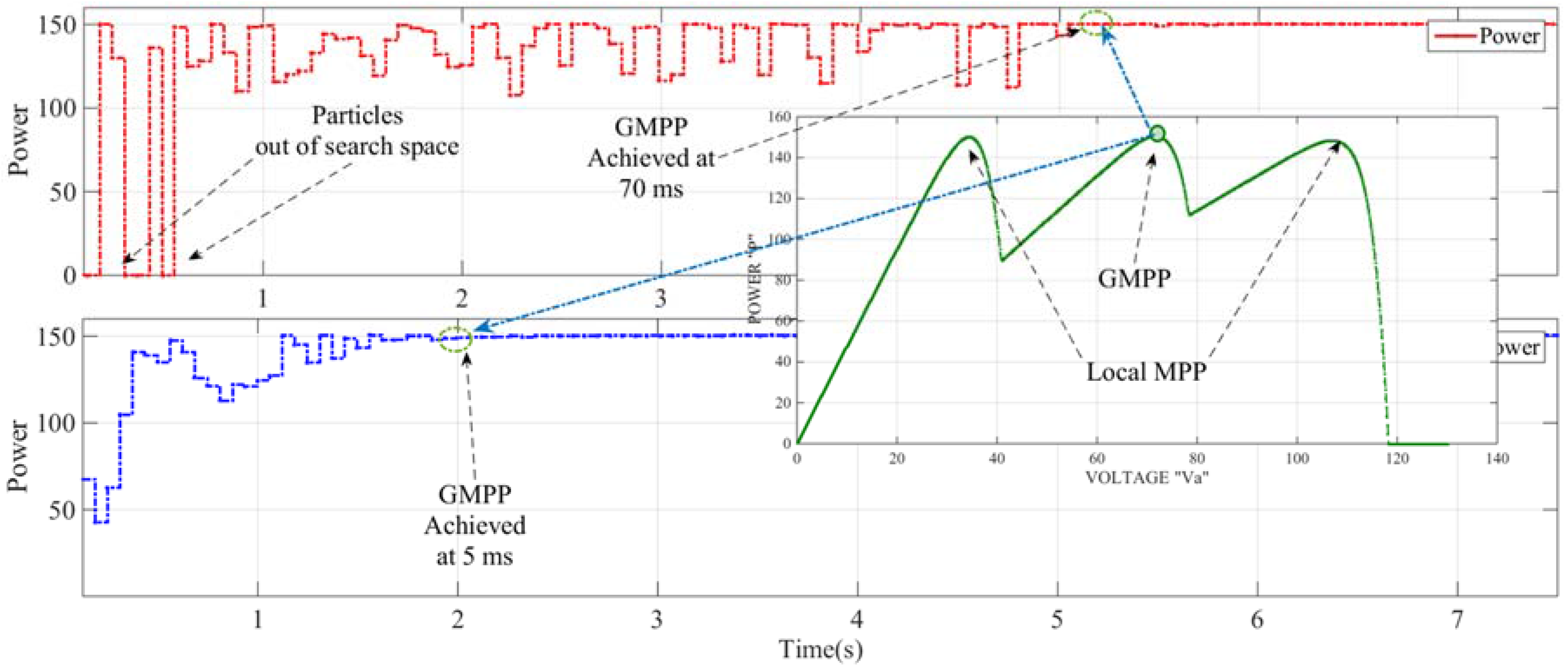
To evaluate the performance of the proposed technique under extreme partial shading conditions, the RMO-based MPPT has been tested under the third scenario. In this scenario, the global maximum occurs among multiple local maxima. Most of the conventional MPPT techniques are able to track the actual MPP if it occurs prior to the local MPP. However, all of these techniques become stuck in the local MPP if the global MPP occurs after them.
Figure 12 shows how the proposed RMO method accurately tracks the actual global MPP regardless of the positions of local MPPs.
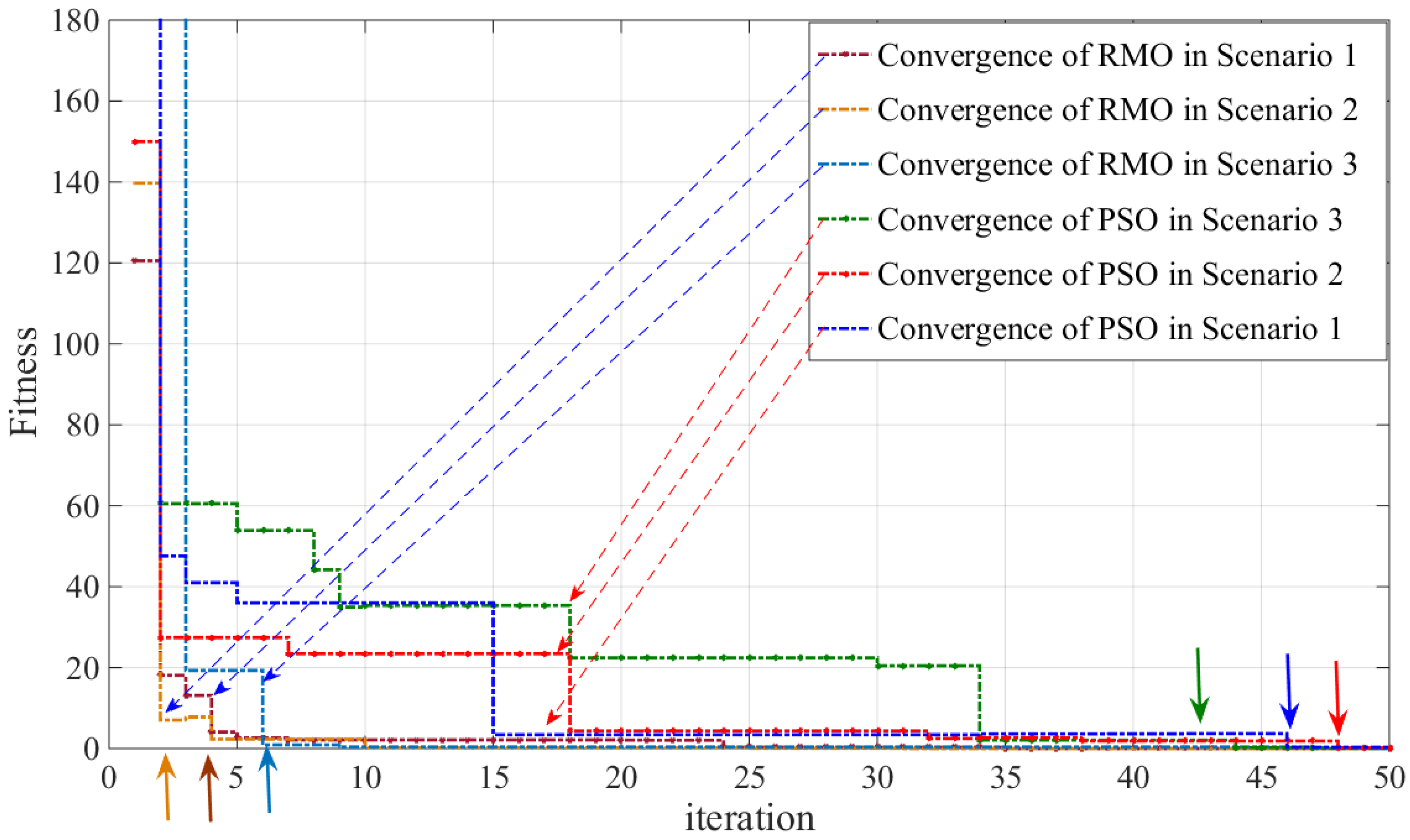
5.2. Convergence Speed, Power Loss, and Computational Cost
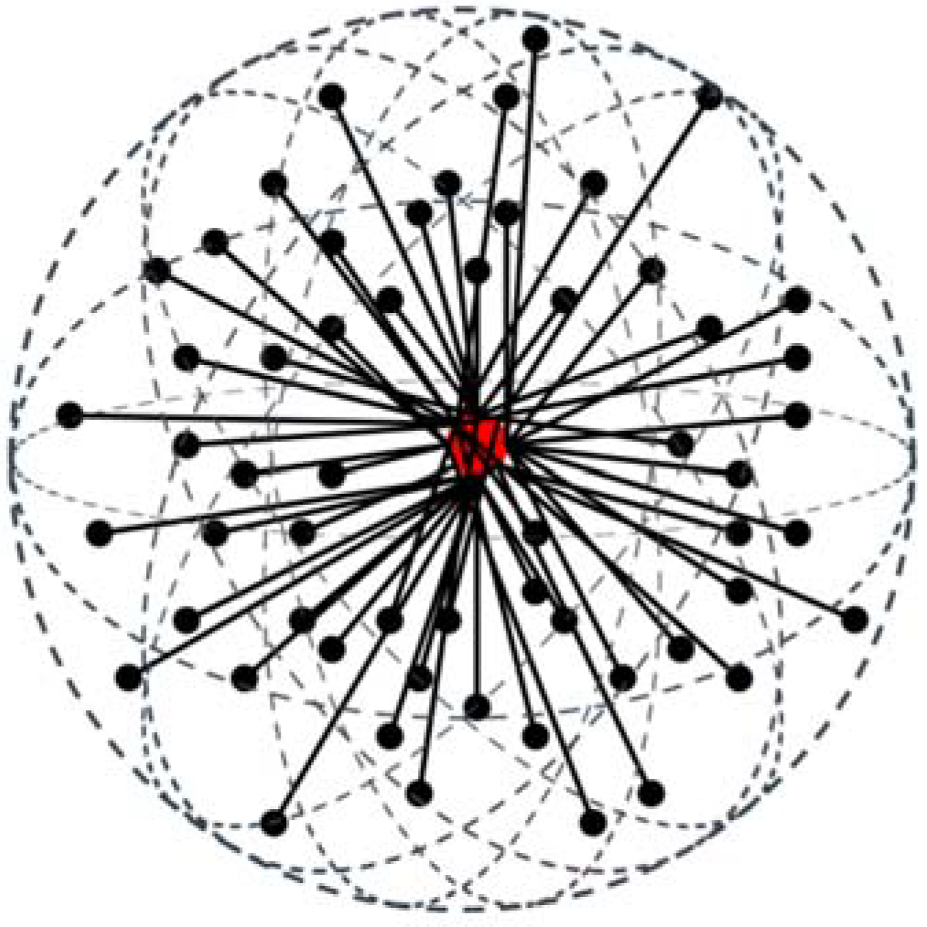
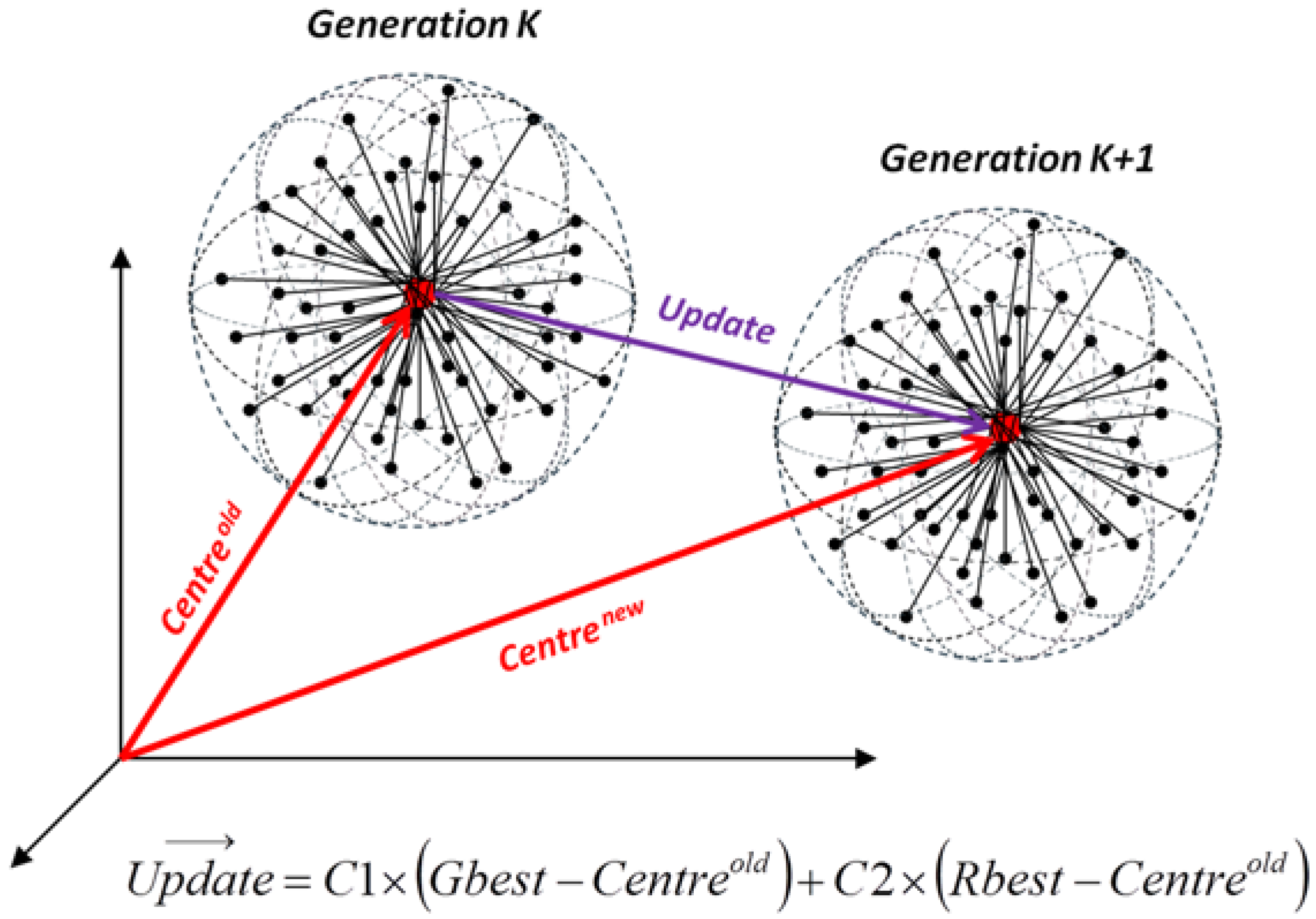
In comparing soft computing methods, their reliability under partial shading conditions is not normally a main comparison criteria. Other factors however such as convergence speed, simplicity, output stability and computational burden are evaluated. One of the distinct advantages of the proposed RMO method is higher speed because the particles scatter around a center with a radiance of
Rbest, which is updated during each iteration. This procedure does not let particles search the unnecessary part of the search space or diverge from the search space. In fact, during the early iterations when the radiance of the sphere is larger, the area of the global MPP is determined, and in the final iterations, the exact global MPP is tracked.
Figure 13 shows the convergence of the proposed RMO technique and PSO technique for all three scenarios.
Another important outcome resulting from the application of the RMO technique for MPPT is the reduction in power loss during both the tracking and steady-state periods. Many of the conventional or hybrid methods result in relatively high power losses. The main reason for this is that most of these methods are based on incremental conductance or hill climbing theories, thereby resulting in constant oscillations at the output of the PV system even when the area of the global MPP is successfully identified. Since the efficiency of the PV system is a critical factor, these oscillations around the MPP can cause significant power loss, which can further reduce the efficiency of the entire PV system. Another effect of these oscillations is voltage instability caused by constant changes in duty cycles. According to the input/output correlation of the DC/DC converters, any slight change in the duty cycle changes the output voltage level of the converter regardless of the type of converter used in the system.
Even methods based on artificial intelligence approaches have large oscillations during the tracking period. The reason for this is that in many swarm-based methods, particles explore all parts of the search space during the running time until the global maximum power point (GMPP) is found; and in evolution-based optimization, the evolution process lasts until the final generations to find and track the GMPP. Many researchers have attempted to overcome this problem by either reducing the random coefficient values or by setting the initial locations for the particles. However, these measures only have minor effect on the oscillations of the output power and reduce the reliability of the control strategy when intensive partial shading happens. Therefore, if the PV system is subject to rapidly varying partial shading conditions, which is very common in residential microgrids, a considerable amount of power loss as well as poor voltage stability will occur.
In RMO-based MPPT, these problems have been addressed. One of the main reasons is that in the procedure of this method, particles scatter in the spherical search space along the radii of
Rbest, which is updated throughout the iteration process.
Figure 10,
Figure 11 and
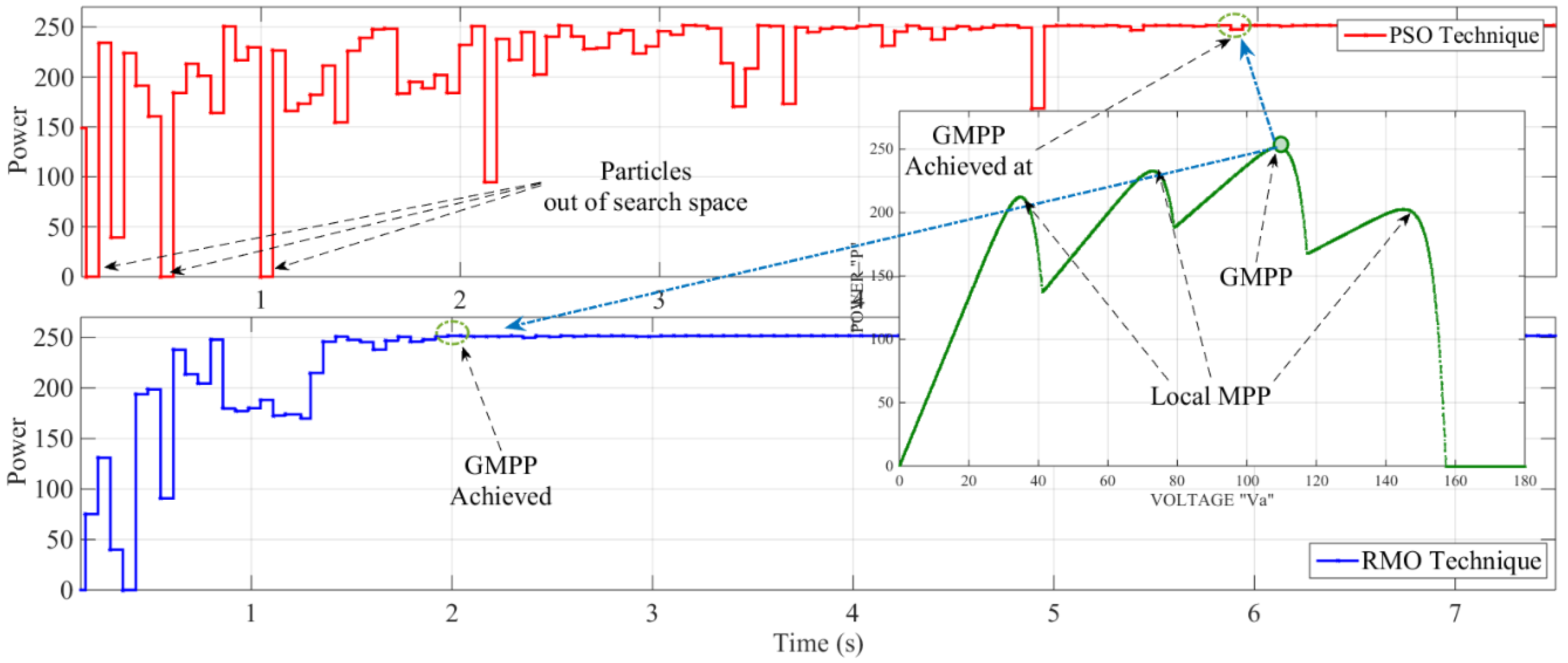
Figure 12 show the difference between the PSO- and RMO-based MPPT methods in terms of convergence speed and output power oscillations while the PV system is operating under the three scenarios. As these Figures show, the GMPP is tracked in less than half of the time than PSO can track this point. In addition, in PSO-based MPPT, because of the role of random coefficients, particles may move out of the search space, as shown in
Figure 10,
Figure 11 and
Figure 12.
Notably, the PSO algorithm applied in this study for the purpose of comparison has been adjusted such that the velocity and the particle movement are limited; therefore, the convergence and oscillations are less than those of the standard PSO.
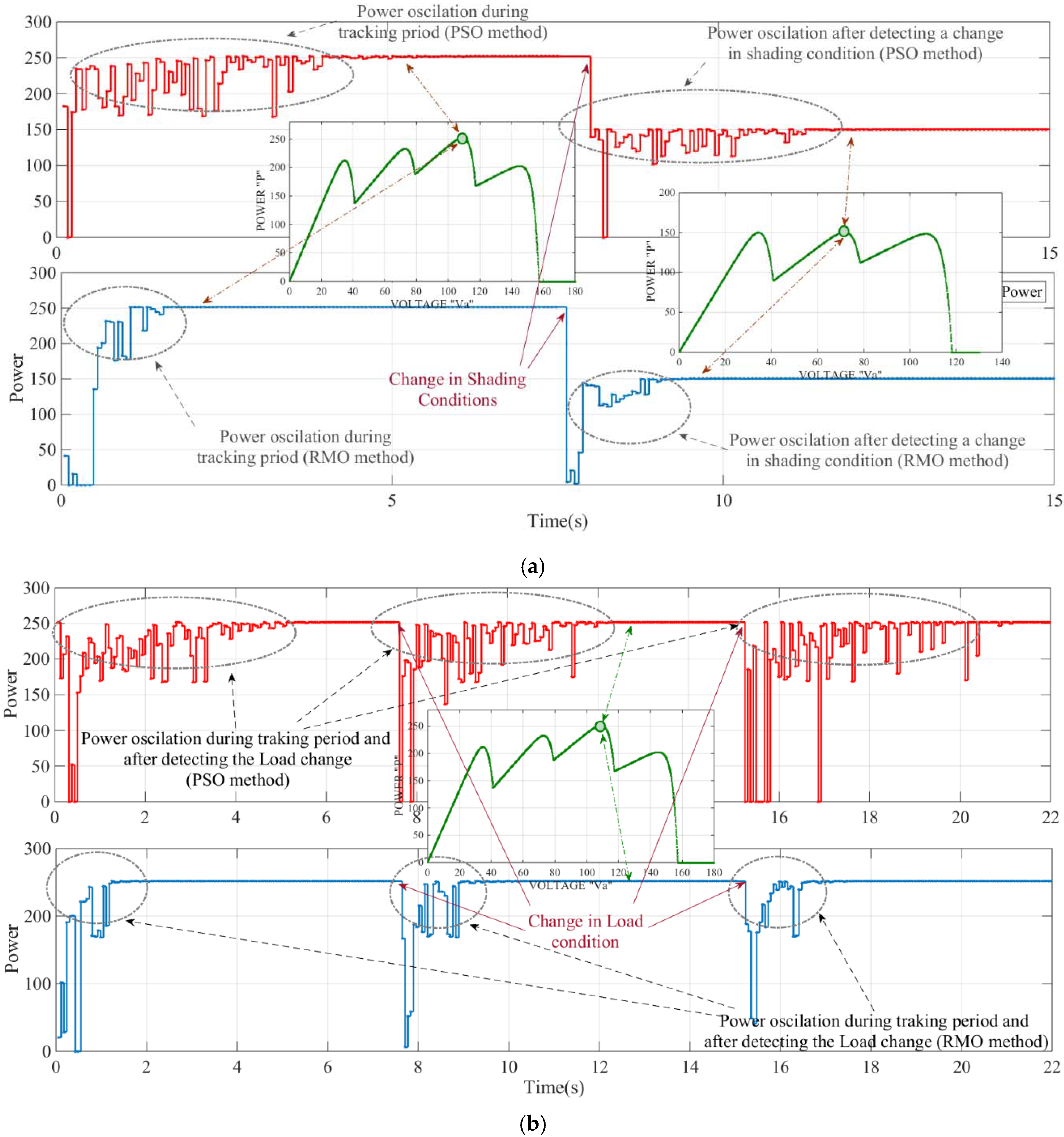
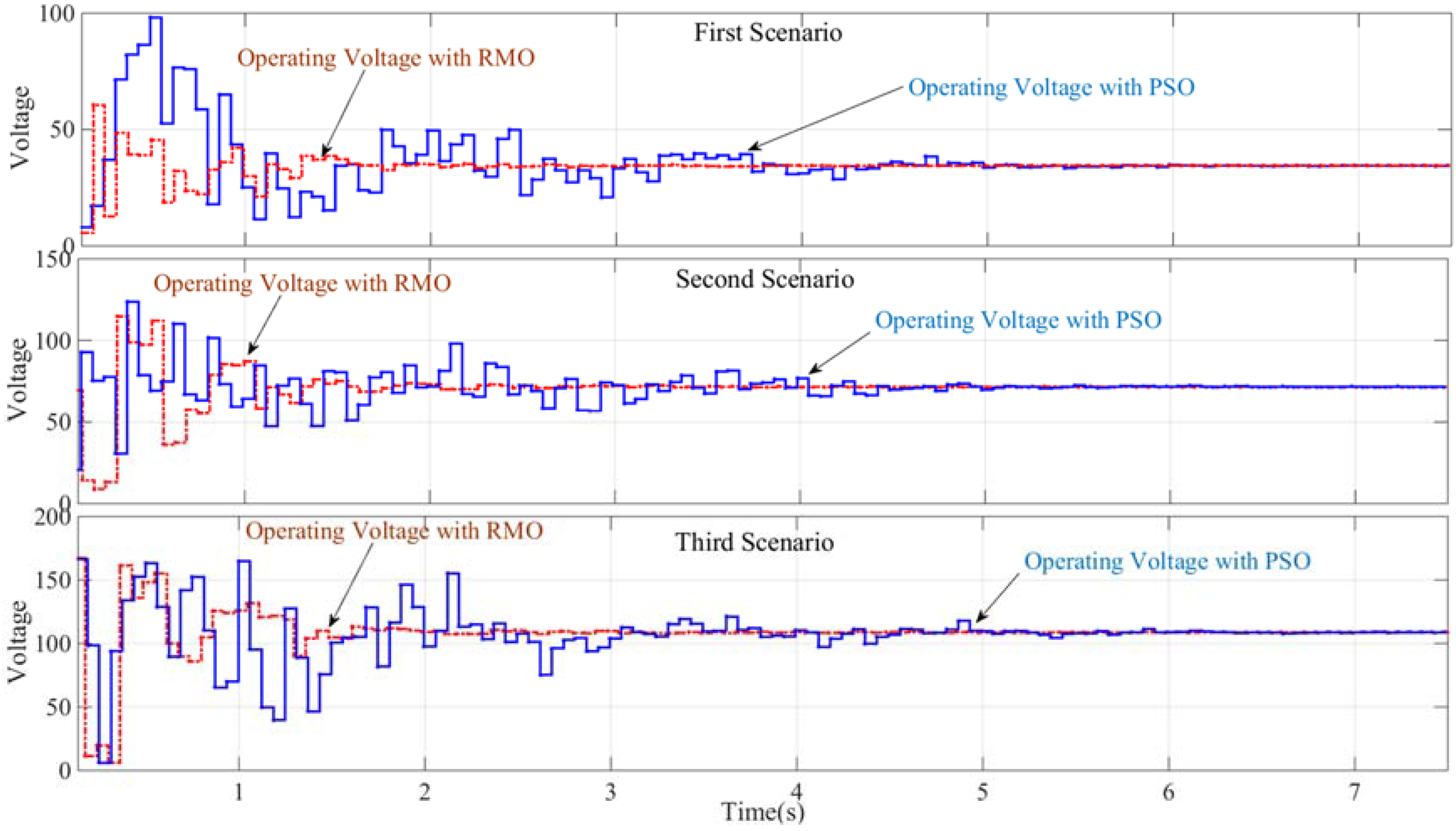
Figure 14 shows the voltage variation during the tracking and steady-state periods at the output of the PV system for the three scenarios for both the RMO- and PSO-based MPPTs. Clearly, both methods have no oscillation around the MPP during the steady-state period. However, the graph shows that, compared with the PSO method, the RMO technique reduces the voltage variation during the tracking period. In order to evaluate the dynamic performance of the proposed method, it was also tested under varying load and shading conditions.
As shown in
Figure 15a, once the system has stabilized after tracking the GMPP, the shading condition abruptly changes from the third to the second scenario where the difference between GMPP and local MPPs is less than 1.5%. The objective of this is to represent varying shading conditions. In the other test, shown in
Figure 15b, after the GMPP has been tracked, the load is halved, reducing from R = 20 Ω to R = 10 Ω at t = 7.8 s. The load is again changed to R = 20 Ω at t = 15.4 s to represent load variation. In both situations, the controller detects the changes using Equation (9) and starts tracking the GMPP under the new conditions. As shown in
Figure 15a,b both methods are capable of dynamically tracking the GMPP under varying load and shading conditions however the introduced DESPO method is much faster compared than the PSO method, resulting in a smoother and more stable output power subject to changing conditions.
The comparison of the proposed RMO method with conventional methods, which are less efficient and unreliable under partial shading conditions, has not been discussed. Rather, the comparison with the modified PSO method has been presented in this paper.
In addition to the fast convergence speed and reduced oscillation during the tracking period, less memory is needed for the proposed RMO technique to find the global solution in the search space. Amongst the common criticisms of soft computation-based MPPT and particularly the PSO method is high computational burden and the need to use a large amount of memory. The reason for this is that the best position of each particle and the best global position of all particles should be remembered. In the proposed RMO technique, however, the system only needs remember the global best position of all particles thereby requiring far less memory and allow the system to be implemented on a lower-cost microcontroller.
6. Conclusions and Future Works
This study aimed to propose a fast, reliable, and system-independent technique for tracking the MPP of the PV system under partial shading conditions. A new fast, simple, and efficient method called RMO is used to track the actual MPP at the output of the PV system. A sequential mathematical modeling procedure is applied to the model to simulate the behavior of the PV system under partial shading conditions. The proposed MPPT method is verified by testing the technique under three partial shading conditions. These predefined conditions are designed to verify the stability, speed, and accuracy of the system. The proposed RMO technique can differentiate the GMPP from local MPPs during mismatching conditions. The main advantages of the proposed technique over the other evolutionary methods are higher efficiency under partial shading conditions, higher speed, simplicity, lower computational cost, and higher output stability. Compared with the PSO method, which has been extensively presented in the literature, the proposed method is faster, less dependent on random coefficients, and needs less memory for processing. As such, the computational burden of the algorithm is reduced, and the technique can be easily implemented on a low-cost microcontroller. This paper represents the first application of RMO for MPPT and we are currently working on the experimental set up in order to extend this research from simulation study to implementation on the physical system.


 ,
, 


