1. Introduction
Due to the absence of common standards, current high-voltage direct current (HVDC) systems operate at different DC voltage levels. Similar to the AC transformer, the DC/DC converter can adapt a DC voltage to any higher or lower voltage level, which may be the only approach to connect and interconnect existing HVDC links operating at different DC voltages [
1,
2,
3]. By blocking all the converters of the DC/DC converter, DC faults can be isolated without significantly affecting the healthy sections of the HVDC system. Additionally, the DC/DC converter can contribute to power flow and DC voltage control and can provide galvanic isolation for safety and system grounding reasons and for the normal operation of converters connected in a multi-terminal HVDC system [
2,
4].
The modular multilevel converter (MMC)-based DC/DC converter is an attractive approach in high voltage applications due to its modular design and relatively low switching losses [
1,
2,
5] and thus is considered in this paper. The DC/DC converter proposed in [
6] can isolate a DC fault quickly once the fault is detected. By utilizing two-level modulation with fundamental frequency, where the AC voltage is clamped to plus or minus half the DC voltage, switching losses, submodule (SM) capacitance, and arm inductances are reduced. However, the electro-magnetic interference due to a rapid voltage change may be destructive.
A DC/DC converter with trapezoidal modulation is introduced in [
2]. By blocking both MMCs in the DC/DC converter, a local DC fault, which occurs at the same branch as the DC/DC converter, can be isolated rapidly. The SM voltages are utilized to generate trapezoidal output voltages and reduce the d
v/d
t. However, the remote fault applied at the main HVDC link is not considered and it is a challenge to design the high voltage AC transformer for trapezoidal AC waveforms.
Besides the fast DC fault isolation capability, the DC/DC converter with sinusoidal modulation presented in [
1,
7] overcomes the EMI issue and simplifies the high voltage AC transformer design, which makes it preferred in HVDC applications.
Different modulation techniques are assessed in the referenced literature to improve the performance of the DC/DC converter with a focus on normal operation. During an AC fault, the half-bridge (HB)-based MMCs (HB-MMCs) still have full current control capability and do not suffer significant overcurrents. However, it is vulnerable to DC faults, where the fault currents flow through the antiparallel diodes from the AC side into the DC fault after the blocking of the MMC. The DC fault protection is thus considered in this paper. During a DC fault, all the HB-MMCs in the DC/DC converter have to be blocked to isolate the DC fault, as the adopted HB-MMCs do not have DC fault blocking capability.
The three-terminal DC/DC converter presented in [
7] can isolate a fault by blocking only one MMC in the DC/DC converter while the other converters continue operating. However, the hybrid MMC is adopted to obtain DC fault blocking capability for each converter. Compared to a conventional DC/DC converter composed of HB-MMC, the capital cost, losses, and volume are increased making it undesirable for HVDC application.
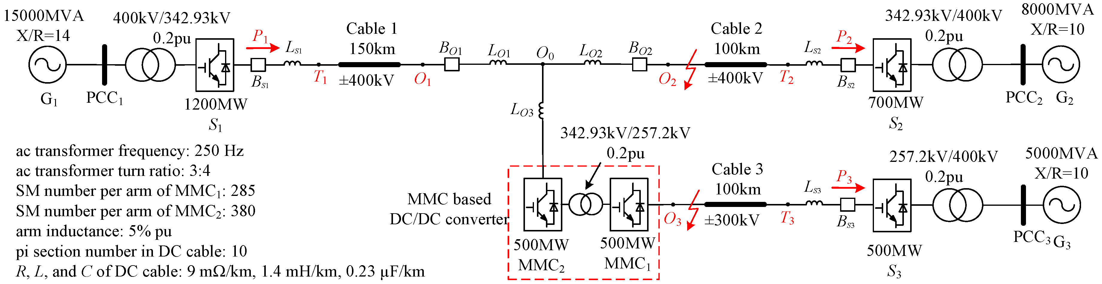
Figure 1 shows a radial three-terminal HVDC system with a symmetric monopole structure, which is considered in this paper. Station
S3 with ±300 kV DC voltage is connected to the main ±400 kV HVDC link through a front-to-front DC/DC converter to match the different DC voltages and isolate any local fault on Cable 3. Stations
S1 and
S3 regulate the DC voltages of the DC network, while
S2 injects rated active power
P2 into the AC grid
G2. In the DC/DC converter, MMC
1 regulates the AC voltage, while MMC
2 operates in an active power control mode and exports rated power
P3 from the main DC-link to the AC-side. All the converters are modeled as conventional HB-MMCs using average models.
If a DC fault occurs on Cable 2 (remote fault for the DC/DC converter), it is desirable that the DC/DC converter continues operating to maintain power transfer between stations
S1 and
S3, while the fault is isolated by the DC circuit breaker (DCCB)
BO2 at the DC-link node. A mechanical DCCB in series with fault current limiting inductance is more likely to be used in a future super DC grid due to low conduction losses and capital cost [
8,
9]. However, the response of conventional mechanical circuit breaker is slow, and the DC/DC converter still endures a high current stress during the response time. To avoid overcurrents in the DC/DC converter in continuous operation, active fault current control is proposed in [
10]. However, the response of the DC/DC converter during a local fault on Cable 3 is not discussed.
For a local fault on Cable 3, the DC/DC converter is blocked to rapidly isolate the fault and operate stations
S1 and
S2 continuously. Conventionally, both the MMCs in the DC/DC converter are blocked [
1,
2,
6]. This paper proposes standby operation of the DC/DC converter during a local fault, where only the MMC (MMC
1) connected to the faulty cable is blocked while the other MMC (MMC
2) continues operating and controls the AC voltage of the DC/DC converter at zero.
The main contribution of the paper is on the development of the improved AC voltage control strategy of the DC/DC converter, considering both normal operation and a local DC fault. In normal operation, the AC voltage is actively set according to the DC voltages of the converter to effectively utilize the DC voltage and generate higher output AC voltages. This significantly decreases SM capacitance and conduction losses of the DC/DC converter, yielding reduced capital cost, volume, and higher efficiency. Additionally, the standby operation during a local DC fault is proposed, where only the MMC connected to the faulty cable is blocked while the other MMC remains operational with zero AC voltage output. The proposed standby operation regulates the SM capacitor voltages at the rated value and avoids the decrease of the capacitor voltages after the blocking of the DC/DC converter. Moreover, the fault can still be isolated as quickly as the conventional approach, where both MMCs are blocked, and the DC/DC converter is not exposed to the risk of overcurrent.
This paper is organized as follows. The higher AC voltage operation of the DC/DC converter in normal operation is presented in
Section 2. In
Section 3, the influence of the increased AC voltage operation is addressed.
Section 4 proposes standby operation of the DC/DC converter during a local DC fault. Performance of the proposed control strategy is assessed in
Section 5.
Section 6 draws conclusions.
2. Increased AC Voltage Operation of DC Transformer
The AC current, like the DC current, flows through MMC arm semiconductors. With increased AC voltages, the AC currents are correspondingly reduced to transfer rated power, yielding lower losses, especially conduction losses. Thus, MMCs are sensitive to AC voltage, which is preferably higher to reduce conduction losses and SM capacitances. However, the AC voltages need to be within the MMC output voltage capabilities to avoid over-modulation and ensure converter dynamics. When an MMC is a terminal station, the voltage of the AC grid connected to the MMC is allowed to fluctuate in the range of ±10% and thus the modulation index of the MMC terminal station is conventionally set between 0.75 and 0.85 [
11,
12]. Moreover, the AC voltage of the DC/DC converter is controllable and regulated by one MMC of the DC/DC converter. As a result, by properly setting the AC voltage of the DC/DC converter, the conduction losses can be significantly reduced while avoiding over-modulation [
7].
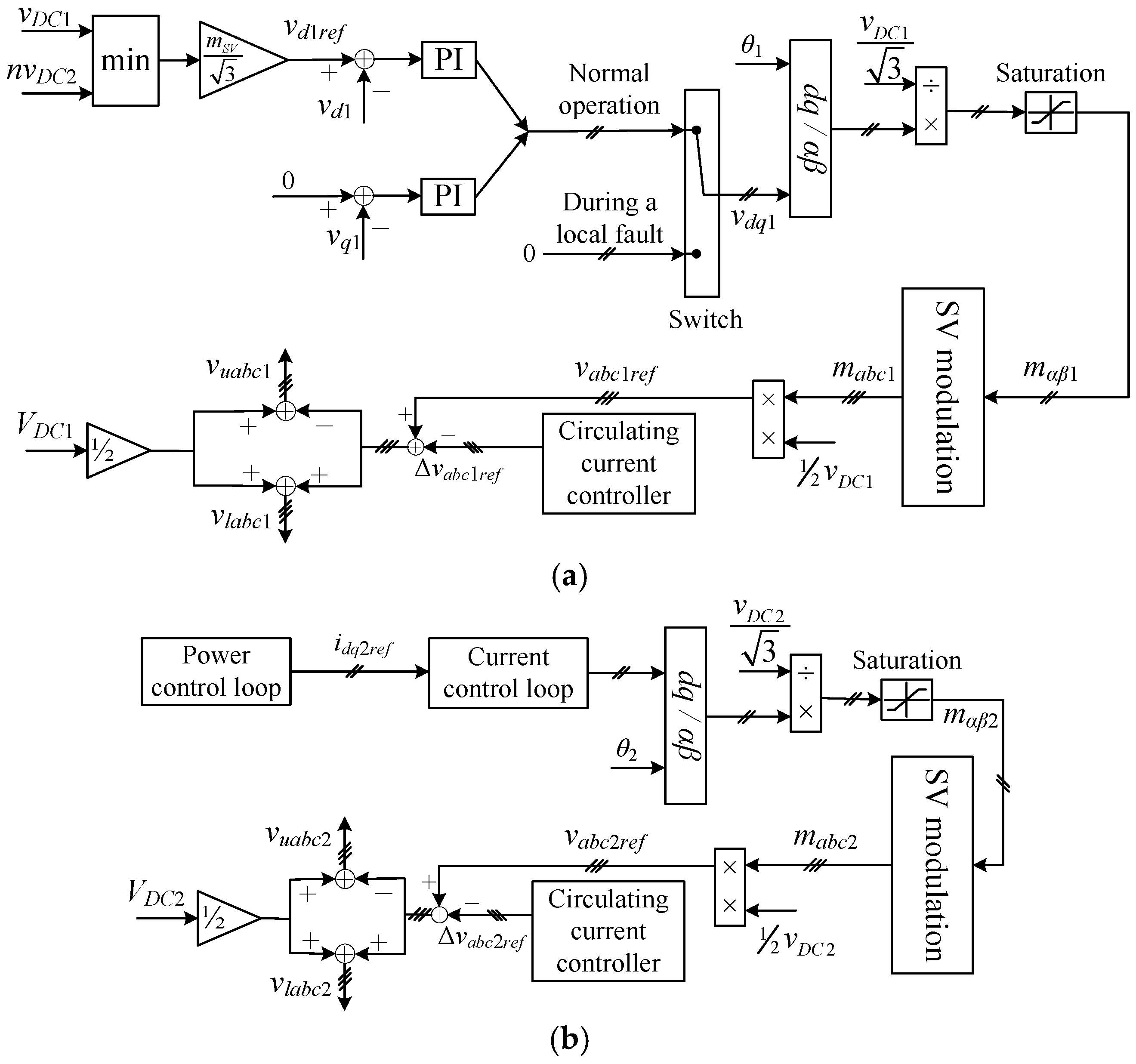
In the presented increased AC voltage operation of the DC/DC converter, the modulation index is increased and can be set close to unity while avoiding over-modulation and retaining good dynamics. With a predefined higher modulation index, the AC voltages are determined by the DC voltages of the DC/DC converter, as shown in
Figure 2. MMC
1 in the DC/DC converter operates in an AC voltage control mode and its control strategy is shown in
Figure 2a, where PI control is used to accurately set the AC-side voltage of the DC/DC converter. The input voltage of the
dq/
αβ block
vdq1 is set by the AC voltage controller in normal operation and is switched to zero after a local DC fault is detected (i.e., standby operation, as will be discussed in
Section 4). MMC
2 is assigned to control the active power with a control strategy illustrated in
Figure 2b. Space vector (SV) modulation is used in both MMCs.
At the terminal stations, the
q-axis component of the grid voltage is conventionally regulated at zero by a phase lock loop (PLL) [
13]. Differently, as shown in
Figure 2a, no PLL is required in MMC
1, which controls the AC voltage of the DC/DC converter. With the
q-axis voltage reference set at zero as illustrated in
Figure 2, the
d-axis voltage reference
vd1ref is set according to the two DC voltages of the DC/DC converter (
vdc1 and
vdc2). The minimum of
and
is the
d-axis voltage reference:
where
n is the AC transformer turn ratio, determined by the DC voltages of the DC/DC converter. By actively setting the AC voltage of the DC/DC converter according to Equation (1), the modulation index can be higher than the conventional approach [
11,
12] and the voltage generating capability of the DC/DC converter is effectively utilized to reduce conduction losses and SM capacitance, while the AC voltages are always within the converter control range, which avoids over-modulation and ensures good dynamics for the DC/DC converter. Considering the voltage drop on the inductances, the modulation index
is lower than unity and is set at 0.95 in this paper. Even with such a high modulation index, the DC/DC converter still shows good dynamics during the studied fast power reversal process, as will be demonstrated in
Section 5.
At conventional MMC terminal stations with high AC voltage, the DC fault currents are higher due to the higher AC voltages. However, for the DC/DC converter, the fault currents can be suppressed to zero rapidly by the proposed standby operation as will be discussed in
Section 4, even with increased AC voltages. As a result, increased AC voltage operation of the DC/DC converter has no adverse influence on DC fault currents. As the AC voltage is set by one MMC in the DC/DC converter and both MMCs operate with increased AC voltages, the turn ratio of the AC transformer, which is used for galvanic isolation and voltage matching, remains unchanged.
4. Standby Operation of the DC/DC Converter during a Local Fault
Although SM capacitor discharge through a DC fault path can be avoided by blocking the MMC, the energy stored on the SM capacitors is dissipated slowly due to the non-ideal behaviors of devices in practice, such as the capacitor leakage, the equivalent series resistance (ESR), the wiring resistance, and the collector-emitter cutoff current of IGBT ICES. This causes a SM voltage decrease. As ICES and the parasitic resistances are usually small, the SM voltage decrease is slight if the converter blocking time is short.
If the fault lasts long enough, the SM voltages will decrease to a value much lower than rated and will drop to zero eventually. In this condition, after the fault is cleared, the SM capacitors must be charged back to around the rated value as suggested in [
16,
17], and the MMC can then be restarted.
Conventionally, both the MMCs in the DC/DC converter are blocked to isolate a local fault from the healthy sections of the HVDC system. However, it was found in this work that it is unnecessary to block both MMCs in the DC/DC converter during a DC fault. The standby operation of the DC/DC converter during a local fault is thus proposed, where only the MMC (MMC
1) connecting to the faulty cable needs to be blocked, while the other MMC (MMC
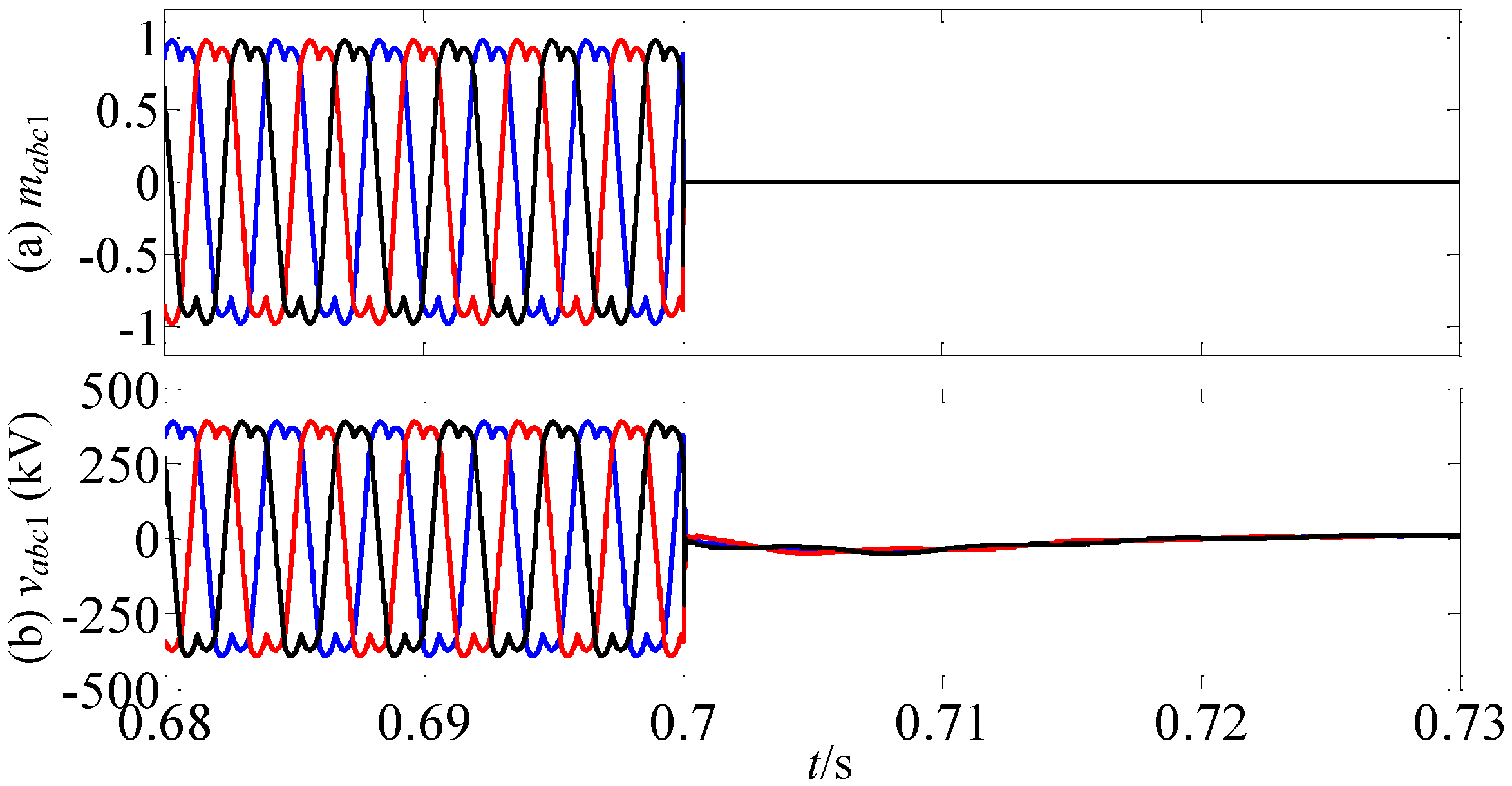
2) continues operating and controls the AC voltage of the DC/DC converter at zero. As illustrated in
Figure 2a, the input voltage of the
dq/
αβ block
vdq1 is switched to zero after a local DC fault is detected. This yields a zero modulation index, and the output voltage
vabc1 is correspondingly controlled around zero, as displayed in
Figure 3. As a result, the SM capacitor voltages of MMC
2 remain at the rated value and the decrease of the SM capacitor voltages after the blocking of the DC/DC converter is avoided. Moreover, the fault can still be isolated as quickly as the conventional approach, where both MMCs are blocked, and the DC/DC converter is not exposed to the risk of overcurrent. The standby operation of the DC/DC converter is a specific application of the proposed AC voltage control during a local DC fault.
The proposed scheme is relatively independent on the fault detection time, which is assumed at 1 ms in this paper [
18]. After a local DC fault occurs at
t0 = 0.7 s, MMC
1 is blocked and MMC
2 is switched to AC voltage control mode at
t0 = 0.701 s. As the DC voltage of MMC
1 drops to zero due to the pole-to-pole DC fault, the AC voltage reference of MMC
2 is set to zero to avoid the fault currents flowing from the AC-side to the DC-side in MMC
1. For MMC
2, as the AC output voltage
vAC is zero, all the arm voltages
varm are controlled at half the rated DC voltage
Vdc:
Thus, half the SM capacitors are connected in the current path in each arm while the other (half) SM capacitors are bypassed:
where
N,
Ni, and
Nb are the total, inserted, and bypassed SMs per arm.
By using voltage balance control, all the SM capacitor voltages of MMC2 are controlled around their rated value. After the fault is cleared, the AC voltage of the DC/DC converter can be restored quickly, benefiting from the stored SM capacitor energy of MMC2. As a result, the SM capacitors of MMC1 can be charged by the AC voltages to quickly restore the operation of the DC/DC converter. Fast restart capability is thus achieved by standby operation of the DC/DC converter.
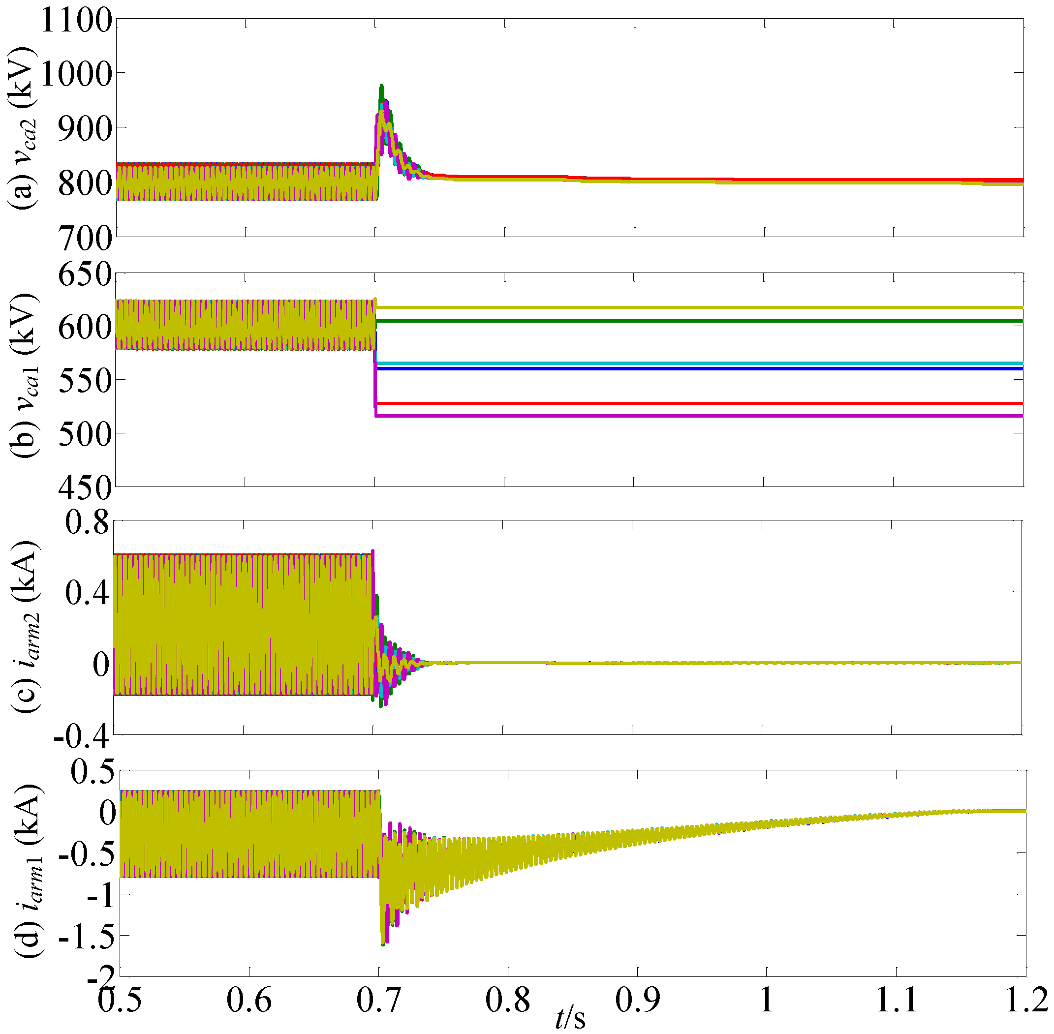
As shown in
Figure 4a, MMC
2 remains operational and the sum of the SM capacitor voltages per arm is well regulated at the rated value (800 kV) with limited overshoot, after a DC fault occurs at
t0 = 0.7 s. The converter arm currents are fully controlled and decay to around zero (
Figure 4c). Although MMC
2 continues operation, the fault can still be blocked due to the zero AC voltage regulated by MMC
2. The arm currents of MMC
1 briefly exhibit fault currents as the DC cable capacitance discharges during the initial period of the DC fault and then decrease to zero (
Figure 4d).
5. Power Reversal Performance of the AC Voltage Control Strategy
Higher output voltage is required for the MMCs in the DC/DC converter to quickly reverse power. However, due to the voltage drop on the DC cables, the DC voltage of the DC/DC converter is potentially lower than the rated value. Additionally, one of the two DC voltages of the DC/DC converter increases during power reversal while the other drops. Fast power reversals place an onerous requirement for the voltage generating capability of the MMC to avoid over-modulation and uncontrolled AC currents in the proposed increased AC voltage operation, where the modulation index is close to unity.
To assess the performance of the AC voltage control strategy during power reversal operation, the simulated scenario assumes MMC
1 in
Figure 1 is initially commanded to import 500 MW from the main DC-link to the grid G
3, then the power flow direction is reversed at time
t = 0.8 s to export 500 MW from G
3 to the main DC-link. The rate of change of active power is restrained to 5 MW/ms and the modulation index is fixed at 0.95.
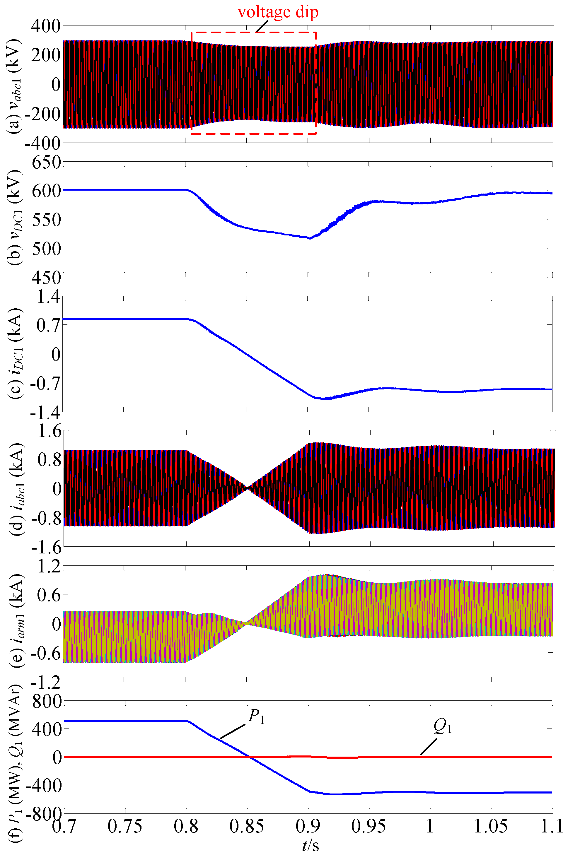
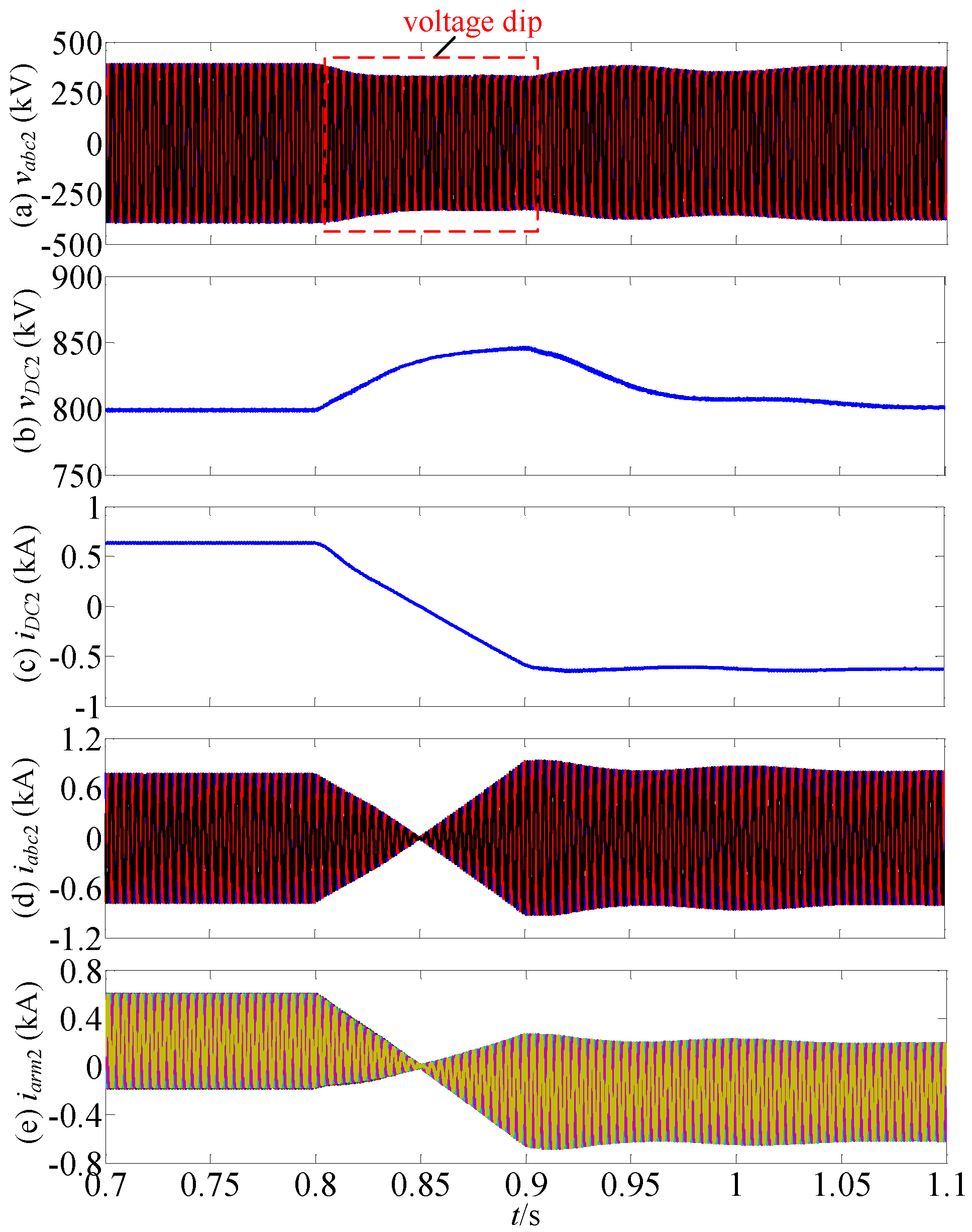
Figure 5 and
Figure 6 show waveforms during power reversal of the test system in
Figure 1 under the mentioned operating conditions. In
Figure 5b, limited DC voltage drop is observed by MMC
1. This results in over-modulation and uncontrolled AC currents due to high modulation index 0.95, if the AC voltage remains unchanged during power reversal. To overcome this issue, the AC voltage of the DC/DC converter is actively set according to the two DC voltages, as previous mentioned. As a result, the AC voltage dips in
Figure 5a following the DC voltage drop of MMC
1 during the power reversal. Thus over-modulation and uncontrolled AC currents are actively avoided, while the AC voltage is controlled as high as possible to reduce conduction losses and SM capacitance.
Power reversal is achieved with minimal transient effects in the AC currents and the active and reactive powers of MMC
1 (a converter that regulates AC voltage level) (
Figure 5d,f), as is also the case for MMC
2 (a converter that regulates active power). During active power reversal, as commanded by MMC
2, DC current reverses in both HVDC links, with limited overshoot due to the dynamics associated with the loop inductances of the link (arm and DC cables). The arm currents of MMC
1 and MMC
2 reverse with slight overshoot during power reversal operation, as shown in
Figure 5e and
Figure 6e. Following power reversal, the HVDC transmission system reaches its steady state operating point. The results in
Figure 5 and
Figure 6 show that the DC/DC converter with increased AC voltage operation is able to operate over the entire operating range, with voltage and current stresses in the active and passive devices fully controlled.

