Article

Stator Current Harmonic Reduction in a Novel Half Quasi-Z-Source Wind Power Generation System

College of Electrical and Information Engineering, Hunan University, Changsha 410082, China
*
Author to whom correspondence should be addressed.
Energies 2016, 9(10), 770; https://doi.org/10.3390/en9100770
Submission received: 2 May 2016 / Revised: 11 August 2016 / Accepted: 20 September 2016 / Published: 23 September 2016
(This article belongs to the Special Issue Distributed Renewable Generation)

Abstract

:
The generator stator current gets distorted with unacceptable levels of total harmonic distortion (THD) because impedance-source wind power generation systems use three-phase diode rectifiers. The stator current harmonics will cause increasing losses and torque ripple, which reduce the efficiency and stability of the system. This paper proposes a novel half quasi-Z-source inverter (H-qZSI) for grid-connected wind power generation systems, which can reduce the generator stator current harmonics a great deal. When H-qZSI operates in the shoot-through zero state, the derivative of the generator stator current is only determined by the instantaneous value of the generator stator voltage, so the nonlinear relationship between generator stator current and stator voltage is improved compared with the traditional impedance-source inverter. Theoretically, it is indicated that the stator current harmonics can be reduced effectively by means of the proposed H-qZSI. Finally, simulation and experimental results are given to verify the theoretical analysis.

1. Introduction

In the last decade, wind energy has become the fastest developing form of renewable energy and is widely utilized in power systems. By the end of 2015, there was 142 GW of installed wind energy capacity in the European Union (EU), and wind energy has overtaken hydro as the third largest source of power generation in the EU, with a 15.6% share of the total power capacity [1,2,3,4,5].
In 2003, a novel dc–ac converter, also known as Z-source inverter (ZSI), was proposed by Peng [6]. The ZSI consists of a DC power supply, an impedance-source network and a three-phase inverter bridge [7,8,9,10,11]. As a promising technology for power electronic conversion, voltage fed Z-source inverters can advantageously use the shoot through states to boost voltage in a single stage without extra power switches. Furthermore, with the ability to handle the shoot through states, the reliability of ZSI is substantially improved. Moreover, the output voltage distortion of inverter is reduced, because there is no need to set dead time [12,13,14,15,16,17,18]. To improve on the original ZSI, the quasi-Z-source inverter (q-ZSI) has been developed which features several improvements, such as continuous input current and no need input capacitance. It has no disadvantages when compared to the traditional ZSI, and can be used in any application in which the ZSI would be used [19,20,21,22,23].
Because of the above advantages, these impedance-source inverter topologies have been widely applied in wind power generation system (WPGS) by researchers and engineers on a global scale. In [24,25,26], a new variable-speed wind energy conversion system (WECS) with a permanent-magnet synchronous generator (PMSG) and Z-source inverter was proposed. Control methods were researched for grid-connection and maximum power point tracking (MPPT) in these references. In [27], an improved pulse-width modulation (PWM) strategy was proposed to reduce the Z-source capacitor voltage ripple. As a result, smaller capacitors can be utilized under the same ripple requirements in a Z-source grid-connected wind generation system. In order to enhance the low voltage ride-through (LVRT) capability for Z-source wind power PMSG systems, a combined protection and control strategy including pulse block, battery energy storage system, reverse power tracking were presented in [28]. In [29], an application of q-ZSI to a PMSG with WPGS was presented. The DC-link boost control and AC side output control were presented to obtain the desired DC bus voltage and reduce the impacts of disturbances on grids. A complete quasi-Z-source inverter-based system for wind power generation was modelled and analysed in [30]. In [31], a closed loop controller was developed which monitors wind generator output and adjusts the q-ZSI shoot-through duty cycle employing the third harmonic injection constant boost control technique. The system can provide stable voltages through proper selection of boost factors. In summary, the current study of impedance-source wind power generation systems is confined to grid-connection control and MPPT. As a popular power conversion system, the three-phase diode based rectifier with its advantages of low cost, simplicity and robustness is widely adopted in impedance-source WPGC [32,33,34].
On the other hand, the uncontrolled rectifier, however, seriously distorts the stator current out of the sinusoidal waveform, which has negative influence on the efficiency and stability of the generation system. In this paper, the reason behind the stator current’s high total harmonic distortion (THD) phenomenon is analyzed for the three-phase diode rectifier-based WPGS with traditional impedance-source inverters (i.e., ZSI and q-ZSI) in detail. As the significant contribution of this paper, a novel half quasi-Z-source inverter (H-qZSI) for grid-connected wind power generation systems is proposed, and we found that the derivative of the generator stator current of H-qZSI is only determined by the instantaneous value of the generator stator voltage in the shoot-through zero state working condition. Additionally, the operating principle of the H-qZSI is also given in the inductor current continuous conduction mode (CCM), and a comparison of the nonlinear relationship between the generator stator current and voltage under the existing and improved topology is provided as well. Finally, simulations and experiments are demonstrated to verify the performance of the proposed H-qZSI topology.

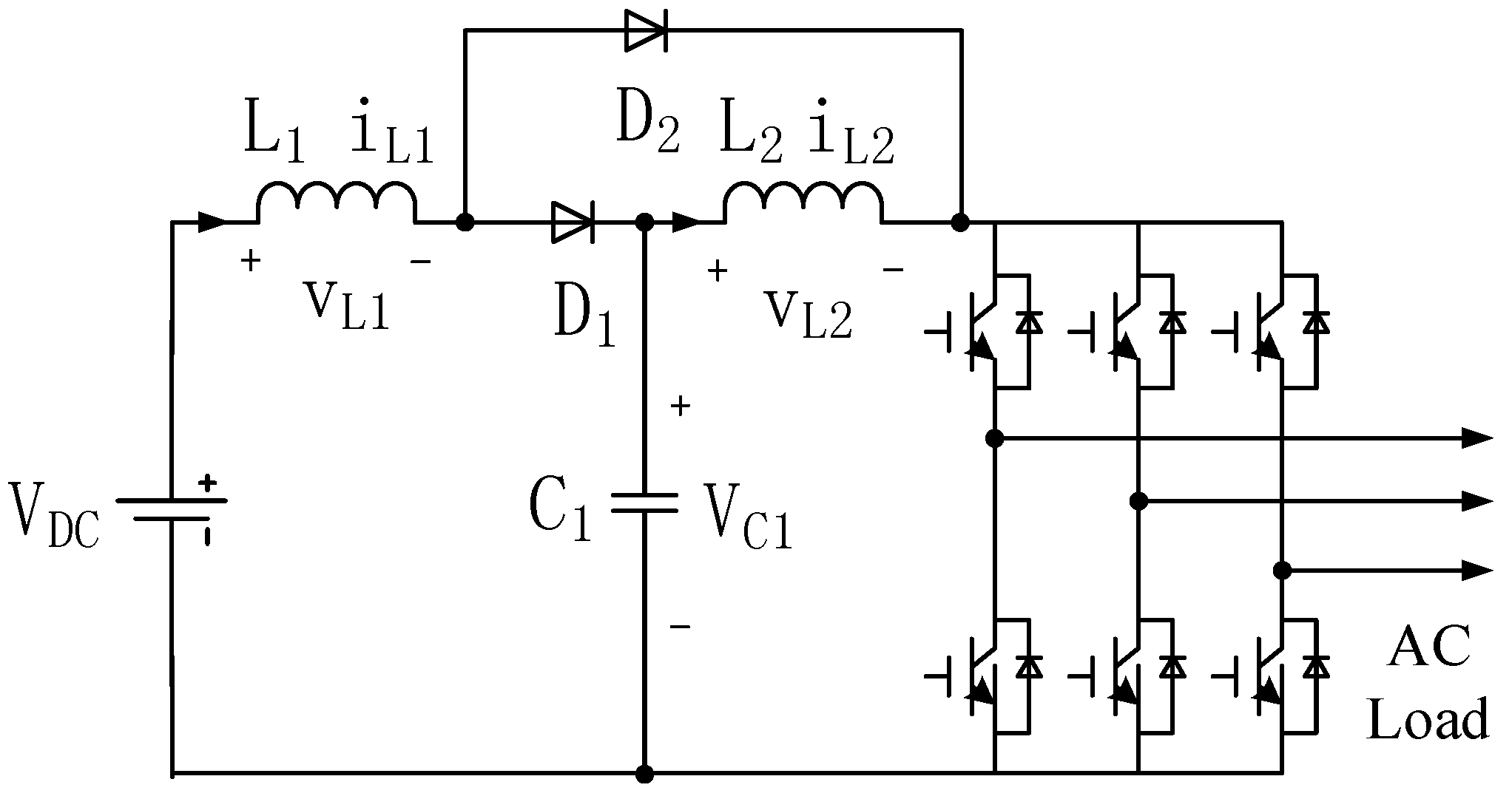
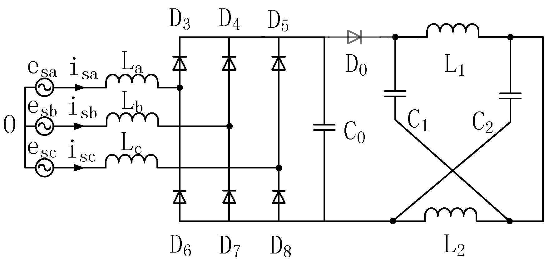
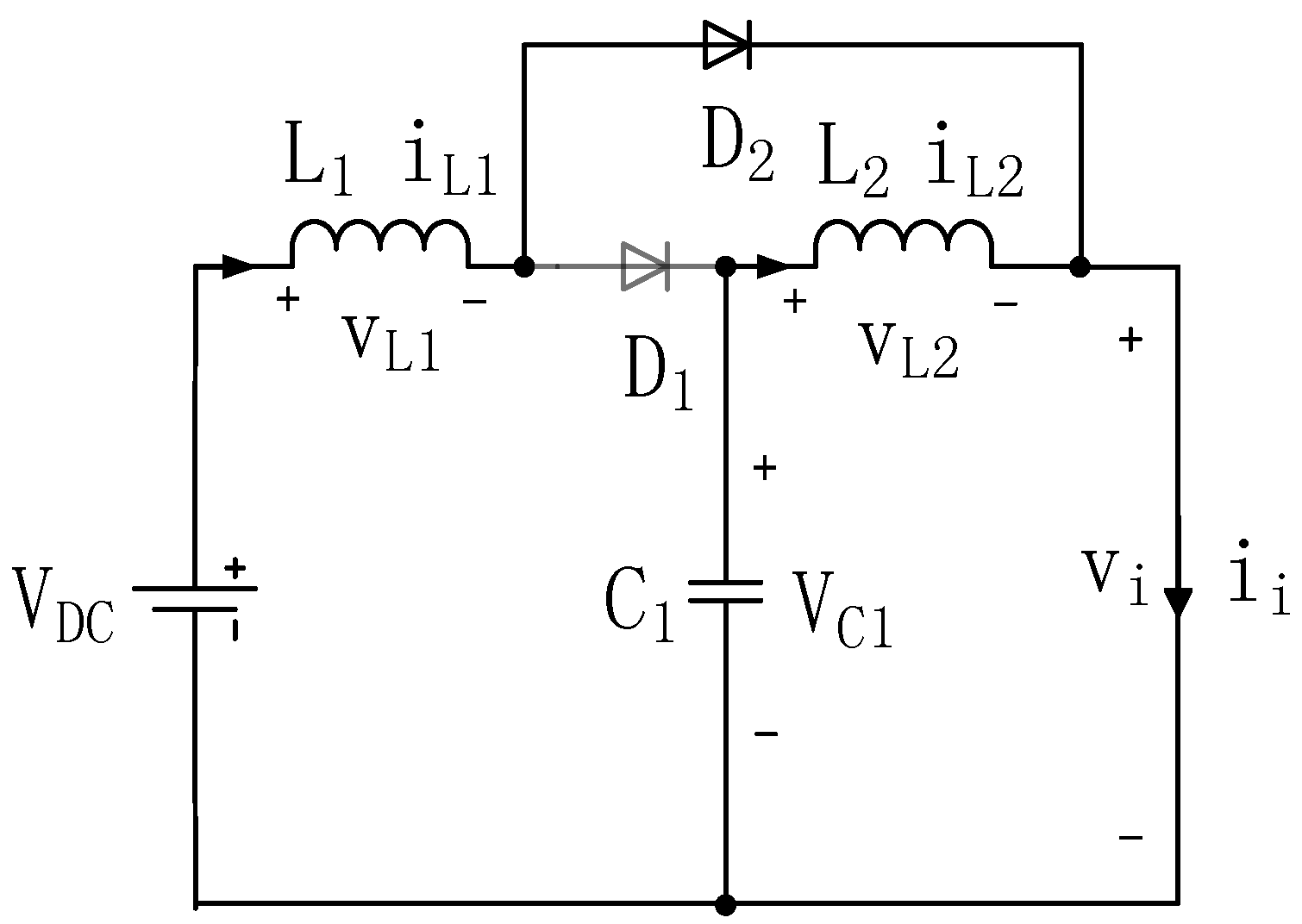
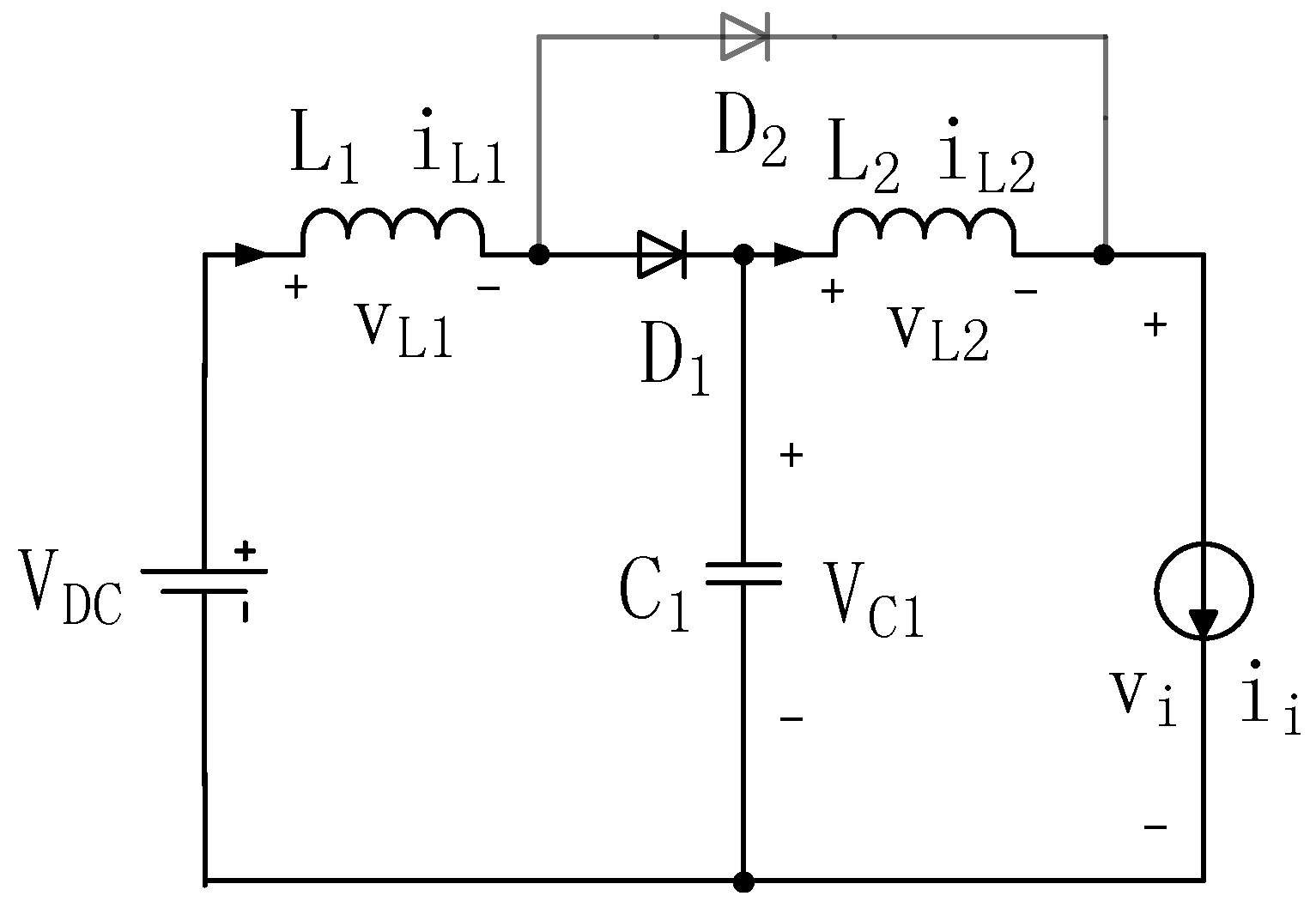
2. Half Quasi-Z-Source Inverter

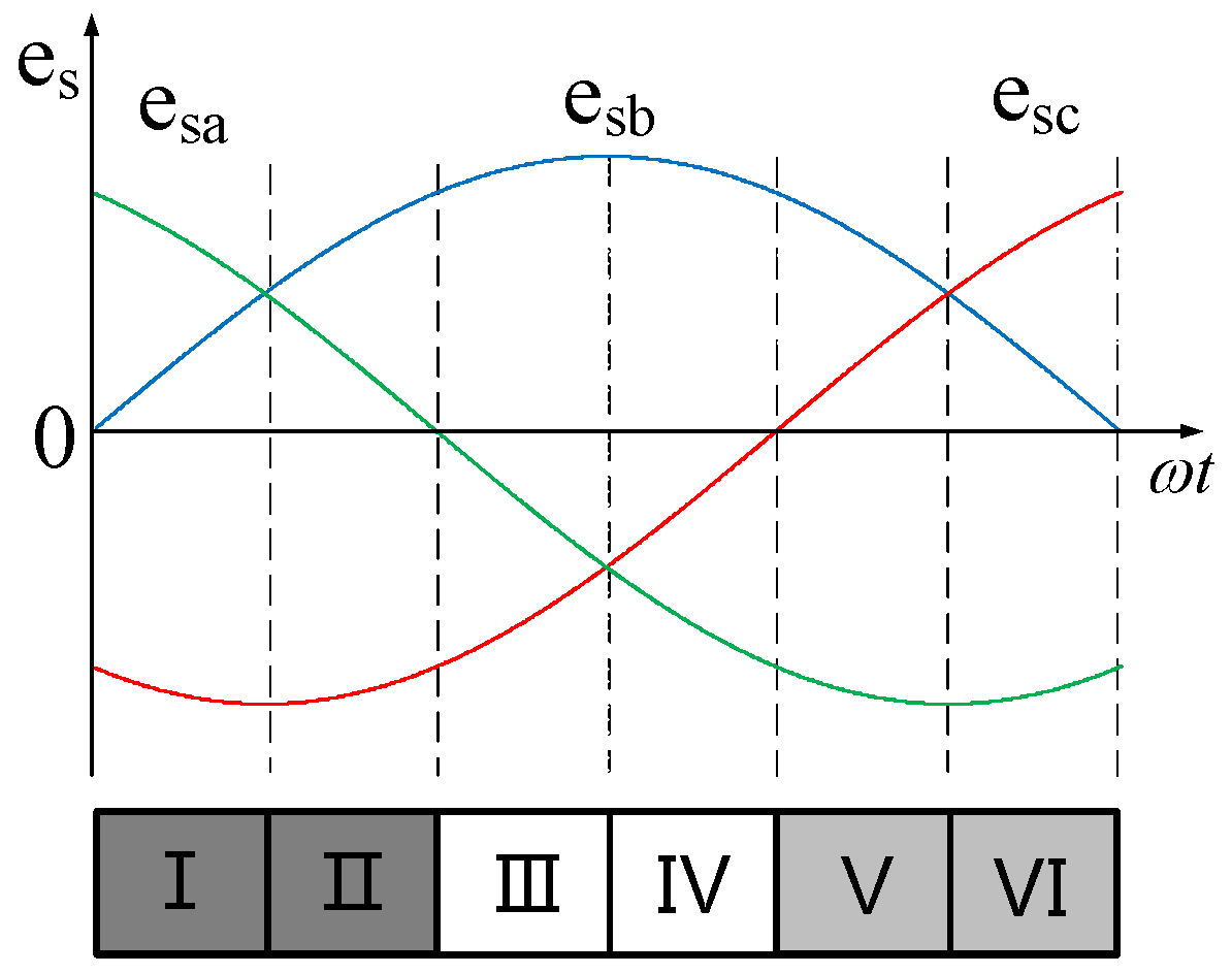
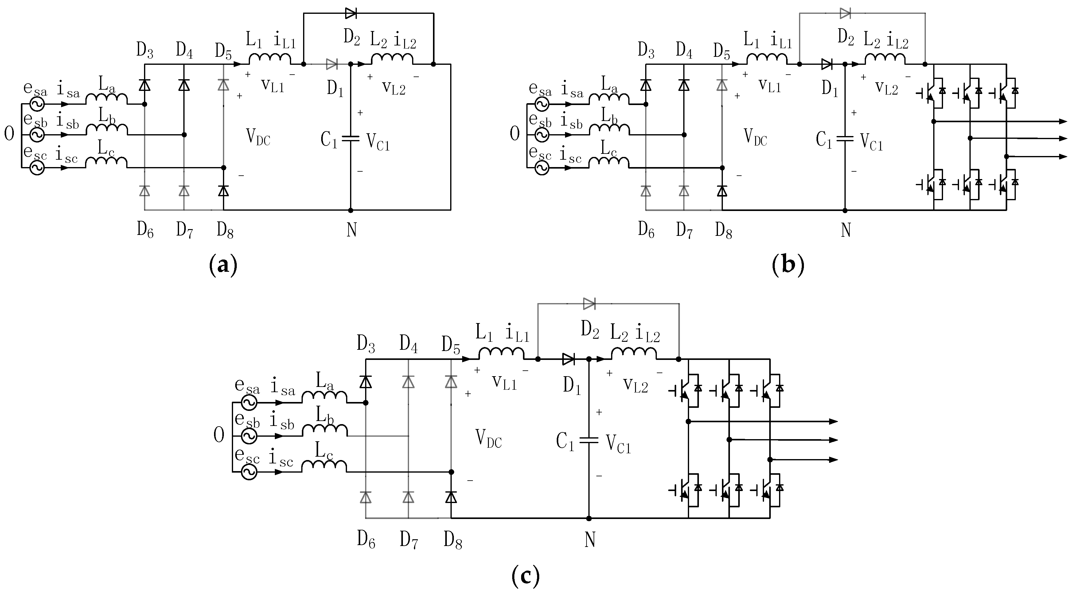
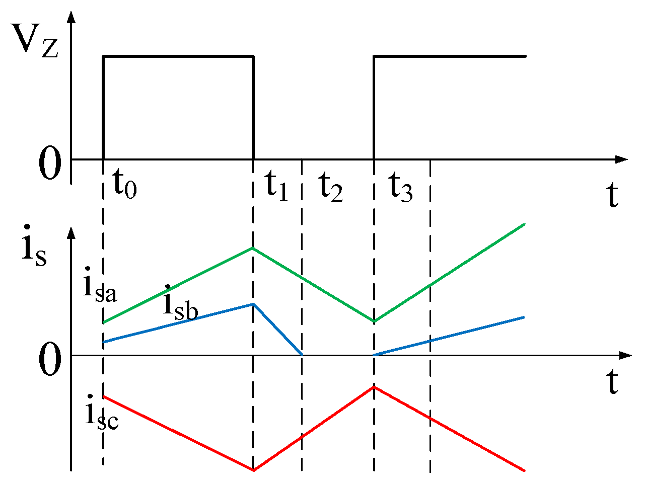
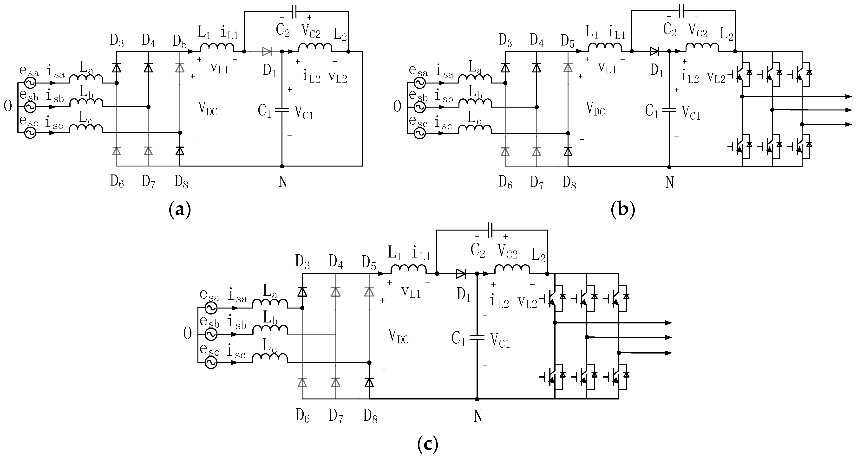
2.1. Working Principle

Figure 1 shows the topology of the proposed half quasi-Z-source inverter (H-qZSI). It employs a unique impedance network to combine the three-phase inverter bridge with the power source. The impedance network consists of inductors L1 and L2, diodes D1 and D2, and a capacitor C1.
As illustrated in Figure 2, the inverter bridge is equivalent to a short circuit when the half quasi-Z-source inverter operates in the shoot-through zero state. In this case, the diode D1 is in the OFF state, and the diode D2 is in the ON state. DC power source is discharged by inductor L1 through diode D2 and shoot-through branch. At the same time, capacitor C1 is discharged by inductor L2 through the shoot-through branch. From Figure 2, the following equations are obtained:
{ V D C = v L 1 + v i V C 1 = v L 2 + v i v i = 0
where VDC is the input voltage of half quasi-Z-source network; vL1, vL2 are the voltages of half quasi-Z-source inductors; VC1 is the voltage of half quasi-Z-source capacitor; and vi is the output voltage of the half quasi-Z-source network.
As shown in Figure 3, the inverter bridge is equivalent to a current source when the half quasi-Z-source inverter works in the non-shoot-through zero state. In this state, the diode D1 is in the ON state, and the diode D2 is in the OFF state. The load is charged by inductors L1, L2, and DC power source. At the same time, capacitor C1 is charged by inductor L1 and DC power source through the diode D1. From the equivalent circuit shown in Figure 3, the equations can be obtained as follows:
{ V D C = v L 1 + V C 1 V C 1 = v L 2 + v i
In steady state, it is noticed that the average voltage of the inductor L1 in one switching period is zero. According to (1) and (2), it can be obtained as:
T 0 T V D C + T 1 T ( V D C V C 1 ) = 0
where T is the time of one switching period, T0 and T1 are the time of shoot-through zero state and non-shoot-through zero state in a switching period, respectively.
From Equation (3), the relationship between the voltage of half quasi-Z-source capacitor and the input voltage of half quasi-Z-source network can be expressed as:
V C 1 = 1 1 d 0 V D C
where d0 is the shoot-through duty cycle, which can be calculated by T0/T.
Similarly, since the average voltage of the inductor L2 in one switching period is zero, the following equation can be obtained:
T 0 T V C 1 + T 1 T ( V C 1 v i p e a k ) = 0
where vipeak is the output peak voltage of the half quasi-Z-source network.
From Equation (5), the relationship between the output peak voltage of the half quasi-Z-source network and the voltage of half quasi-Z-source capacitor can be calculated as:
v i p e a k = 1 1 d 0 V C 1
From Equations (4) and (6), the output peak voltage of the half quasi-Z-source network can be expressed as:
v i p e a k = ( 1 1 d 0 ) 2 V D C
Therefore, the output average voltage of the half quasi-Z-source network can be obtained as:
V i = 1 1 d 0 V D C = V C 1

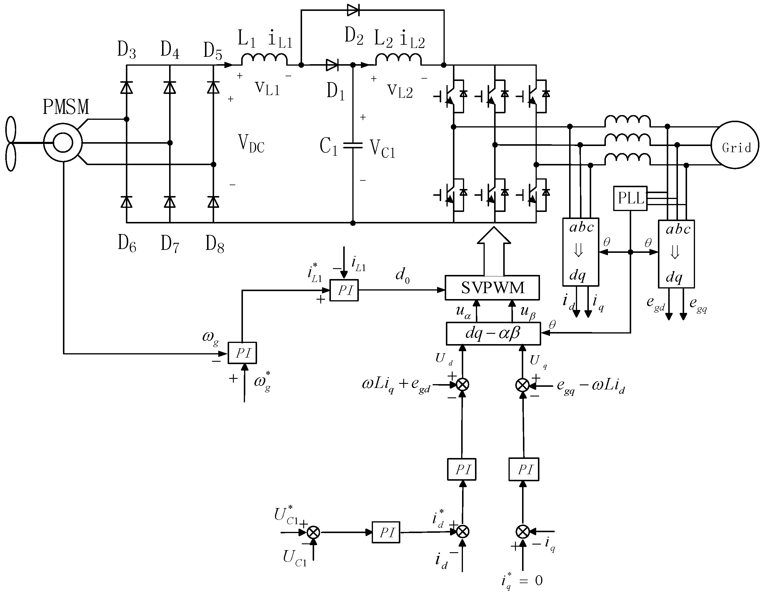
2.2. Control Strategy for H-qZSI

The structure of the control system for s half quasi-Z-source grid-connected wind generation system, which consists of wind turbine, PMSG, three-phase diode rectifier, impedance-source inverter, and grid-connected transformer, is shown in Figure 4.
The d-axis of the d and q coordinates is made to coincide with the grid voltage vector. Thus, active and reactive power control can be achieved by controlling the d-axis and q-axis component of the grid current vector, respectively. The grid-connected current is made to have a unity-power-factor, while the q-axis current is always kept at zero. From Equation (8), it can be seen that the output average voltage of the half quasi-Z-source network will remain stable as long as the voltage of the half quasi-Z-source capacitor stays constant. To make the voltage of the half quasi-Z-source capacitor remain constant, a H-qZSI capacitor voltage outer-loop and d-axis current inner-loop are adopted in the controller. Thus, the generator speed can be changed flexibly by controlling the shoot-through duty cycle. An outer speed control loop is adopted to set the current reference of inductor L1 for active-power control. It ensures that all the power coming from the generator is instantaneously fed into the grid by the half quasi-Z-source inverter. On the other hand, the current inner-loop is designed to control the current of inductor L1. The current controller will provide a shoot-through duty cycle reference for the inverter. The outer speed control loop is utilized for tracking reference value of generator speed. At the same time, the current inner-loop is utilized for making input current coincide with input voltage.

3. Results and Discussion

3.1. Analysis of Input Power Factor

The working principle of the Z-source inverter is given in [6]. It can be obtained that the diode D0 is in the OFF state when Z-source inverter operates in the shoot-through zero state. The equivalent circuit of the Z-source wind power system is shown in Figure 5. In this case, Z-source network is separated from the three-phase diode rectifier, which is responsible for the distortion of generator stator current.
The stator electromotive force (EMF) of permanent-magnet synchronous generator (PMSG) can be expressed as:
{ e s a ( t ) = 2 E S cos ( ω t ) e s b ( t ) = 2 E S cos ( ω t 2 3 π ) e s c ( t ) = 2 E S cos ( ω t + 2 3 π )
where ES is the root mean square (RMS) of the EMF, ω is the rotor angular speed of the PMSG.
In half alternating cycle, the waveform of EMF is divided into six sectors, as shown in Figure 6. The input power factor of half quasi-Z-source inverter is analyzed in sector one below. Since the switching frequency is much greater than the frequency of the EMF, the value of EMF can be considered to be a constant in a switching cycle. The equivalent shoot-through function VZ is made being zero and one when half quasi-Z-source inverter operates in the shoot-through zero state and non-shoot-through zero state, respectively.
A switching cycle is divided into three operation modes during sector one, as shown in Figure 7 and Figure 8. H-qZSI operates in the shoot-through zero state from t0 to t1. In this case, the diodes D2, D3, D4 and D8 are in the ON state, while the diodes D1, D5, D6, D7 are in the OFF state. La, Lb and Lc are the equivalent inductors for three-phase stator windings. The current in inductors La, Lb and Lc is increased. The inductor L1 is charged by PMSG. At the same time, the inductor L2 is charged by capacitor C1.
From Figure 8a, it can be obtained that:
{ e s a L a d i s a d t L 1 d ( i s a + i s b ) d t = v N O e s b L b d i s b d t L 1 d ( i s a + i s b ) d t = v N O e s c L c d i s c d t = v N O
where isa, isb and isc are the three-phase stator current of PMSG, vNO is the voltage between reference point N and O.
La, Lb and Lc are made being equal to L. Adding the three equations in (10), it can be calculated that:
1 3 ( e s a + e s b + e s c ) L 3 ( d i s a d t + d i s b d t + d i s c d t ) 2 L 1 3 d ( i s a + i s b ) d t = v N O
From the symmetry of three-phase EMF and the Kirchhoff’s law, the equation can be obtained as follows:
v N O = 2 L 1 3 d ( i s a + i s b ) d t
From Equations (10) and (12), the derivative of three-phase stator current can be expressed as:
{ d i s a d t = e s a ( 3 L L 1 ) + e s b L 1 3 L 2 + 2 L L 1 d i s b d t = e s a ( 6 L + L 1 ) e s b ( 3 L + L 1 ) 3 L 2 + 2 L L 1 d i s c d t = 3 e s c 3 L + 2 L 1
Equation (13) shows that the derivative of three-phase stator current is only related to the three-phase stator EMF in mode 1, when the system parameters are determined.
H-qZSI operates in the non-shoot-through zero state from t1 to t3, where three-phase stator current is decreased in the first stage from t1 to t2. In this case, the diodes D1, D3, D4 and D8 are in the ON state, while the diodes D2, D5, D6, D7 are in the OFF state. The inductors L1, L2 and the PMSG are discharged by the load. At the same time, the capacitor C1 is charged by the PMSG.
From Figure 8b, it can be obtained that:
{ e s a L d i s a d t L 1 d ( i s a + i s b ) d t V C 1 = v N O e s b L d i s b d t L 1 d ( i s a + i s b ) d t V C 1 = v N O e s c L d i s c d t = v N O
Adding the three equations in (14), it can be calculated as:
1 3 ( e s a + e s b + e s c ) L 3 ( d i s a d t + d i s b d t + d i s c d t ) 2 L 1 3 d ( i s a + i s b ) d t 2 V C 1 3 = v N O
From the symmetry of three-phase EMF and the Kirchhoff’s law, the voltage between reference point N and O can be obtained as follows:
v N O = 2 L 1 3 d ( i s a + i s b ) d t 2 V C 1 3
From Equations (14) and (16), the derivative of three-phase stator current can be expressed as:
{ d i s a d t = e s a ( 3 L + L 1 ) e s b L 1 L V C 1 3 L 2 + 2 L L 1 d i s b d t = e s b ( 3 L + L 1 ) L 1 e s a L V C 1 3 L 2 + 2 L L 1 d i s c d t = 3 e s c + 2 V C 1 3 L + 2 L 1
Equation (17) shows that the derivative of three-phase stator current is related to the three-phase stator EMF and the voltage of capacitor C1 in mode 2, when the system parameters are determined.
The three-phase stator current is decreased in the second stage from t2 to t3. In this case, B-phase stator current is zero. The diodes D1, D3, D8 are in the ON state, while the diodes D2, D4, D5, D6, D7 are in the OFF state. From Figure 8c, it can be obtained that:
{ e s a e s c L ( d i s a d t d i s c d t ) L 1 d ( i s a + i s b ) d t V C 1 = 0 i s b = 0 i s c = i s a
The derivative of the three-phase stator current can be expressed as:
{ d i s a d t = e s a e s c V C 1 2 L + L 1 i s b = 0 d i s c d t = e s a e s c V C 1 2 L + L 1
Equation (19) shows that the derivative of three-phase stator current is related to the three-phase stator EMF and the voltage of capacitor C1 in mode 3, when the system parameters are determined. Figure 9 shows the equivalent circuit of qZSI wind power generation system in each mode.
Similarly, the derivative of three-phase stator current in mode 1 can be expressed as:
{ d i s a d t = e s a ( 3 L + L 1 ) e s b L 1 + L V C 2 3 L 2 + 2 L L 1 d i s b d t = e s b ( 3 L + L 1 ) L 1 e s a + L V C 2 3 L 2 + 2 L L 1 d i s c d t = 3 e s c 2 V C 2 3 L + 2 L 1
Equation (20) shows that the derivative of three-phase stator current is related to the three-phase stator EMF and the voltage of capacitor C2 in mode 1, when the system parameters are determined.
From Figure 9b,c, it can be obtained that the derivative of three-phase stator current utilizing H-qZSI and qZSI is equal in mode 2 and mode 3, respectively.
In comparison with the Equations (20) and (13), the coupling between the derivative of three-phase stator current and impedance-source capacitor is eliminated in the H-qZSI wind power generation system when the system operates in mode 1. Therefore, the nonlinear relationship between generator stator current and stator voltage is improved, and the stator current harmonics are reduced.

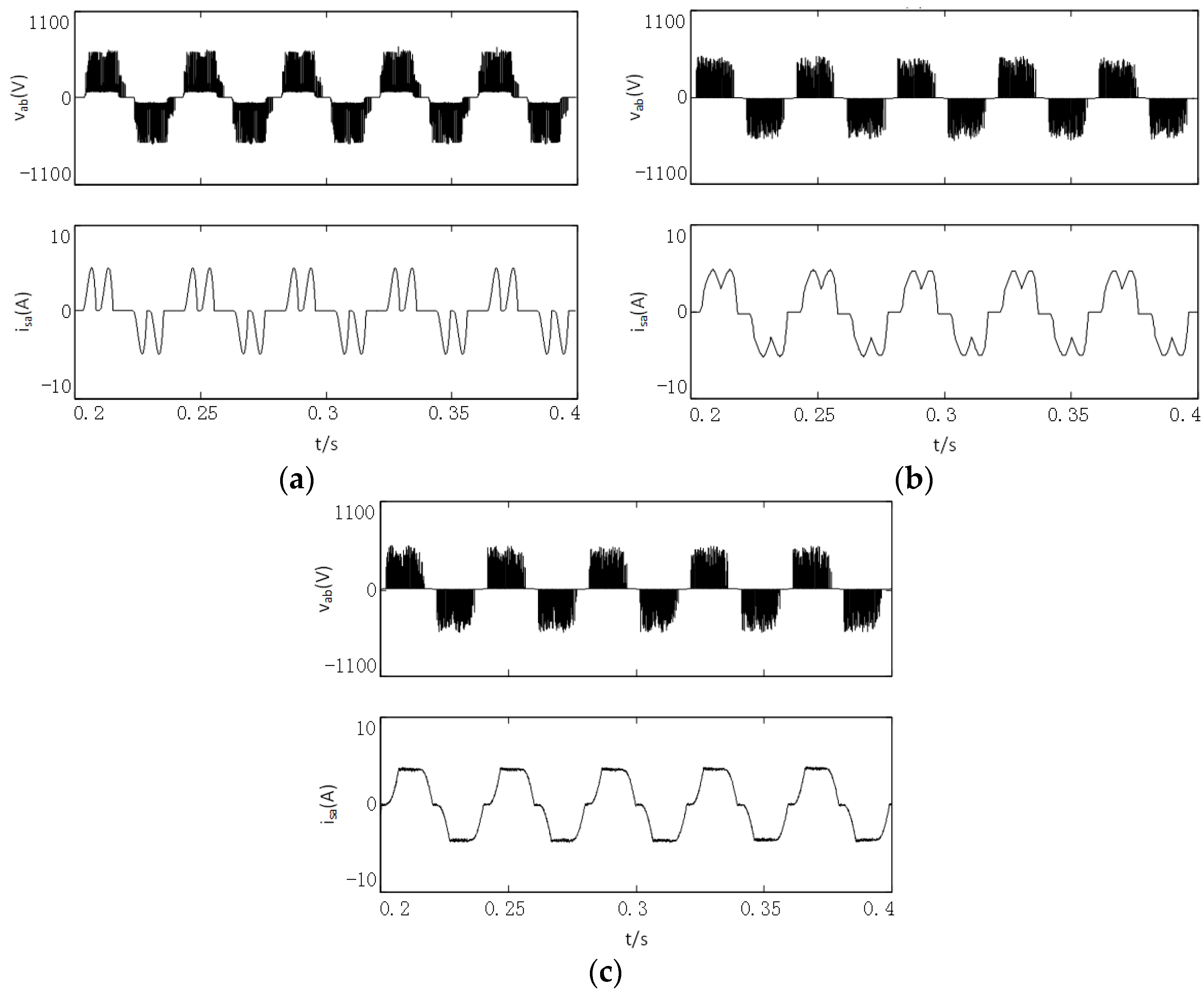
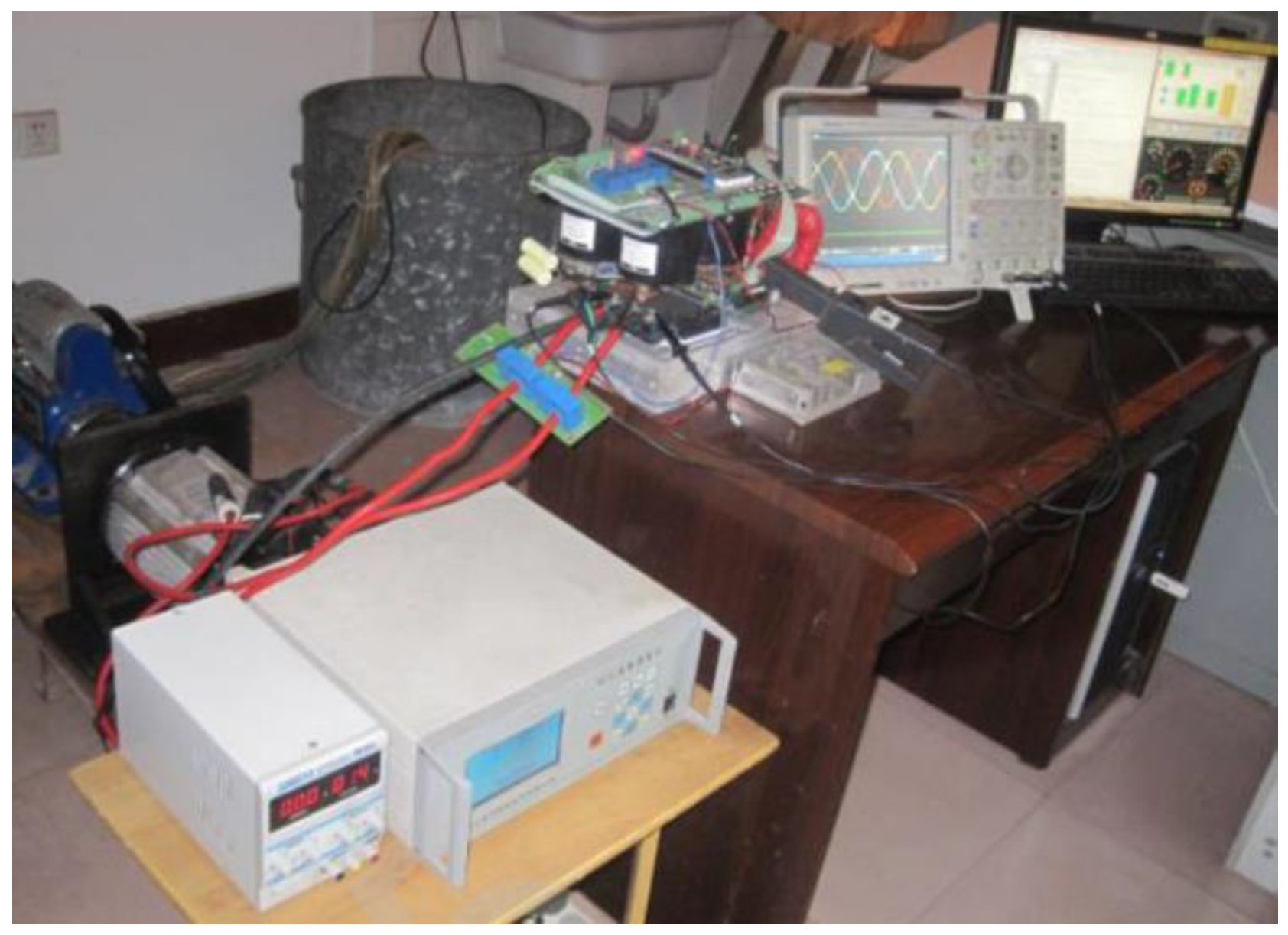
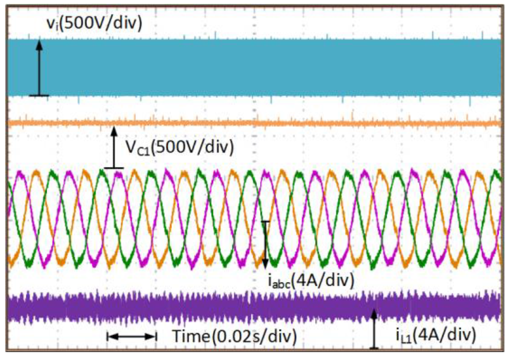
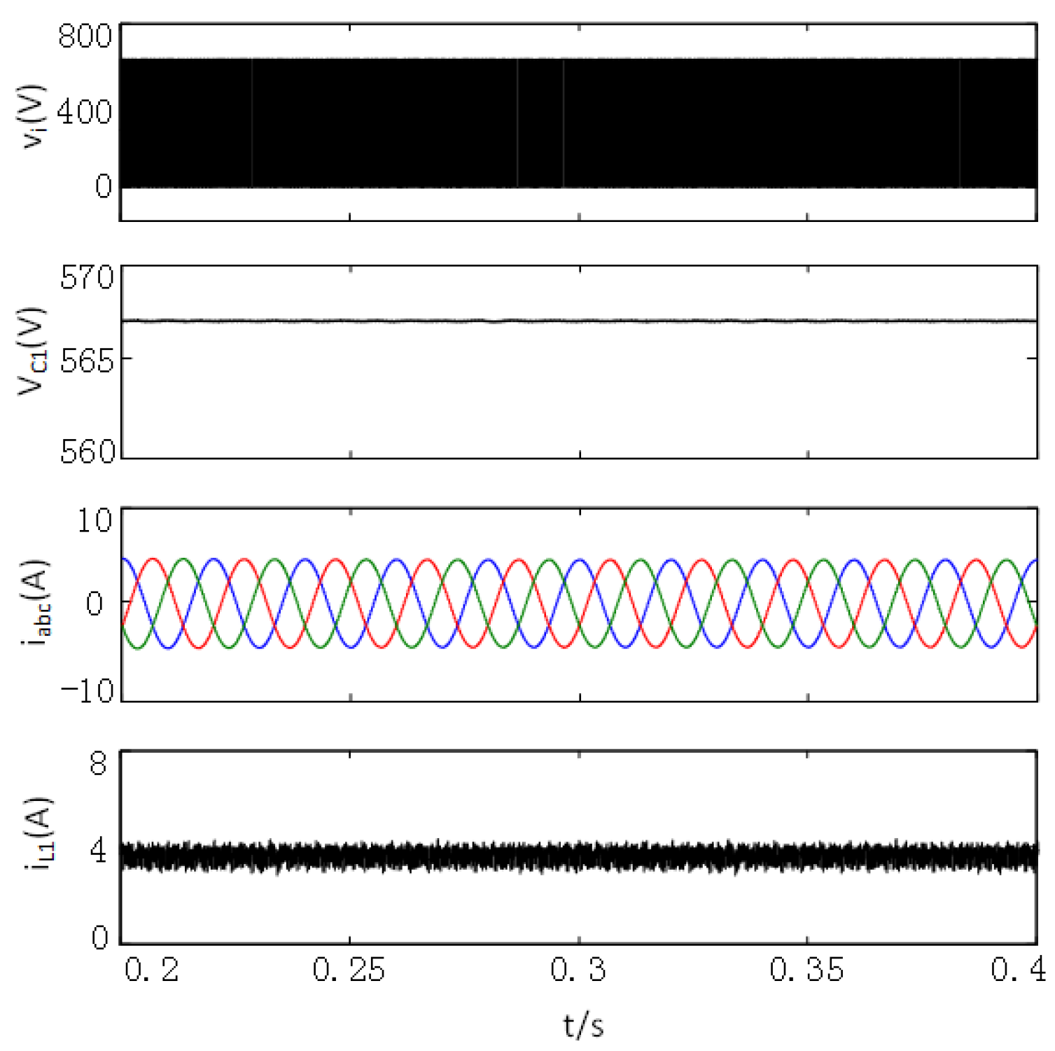
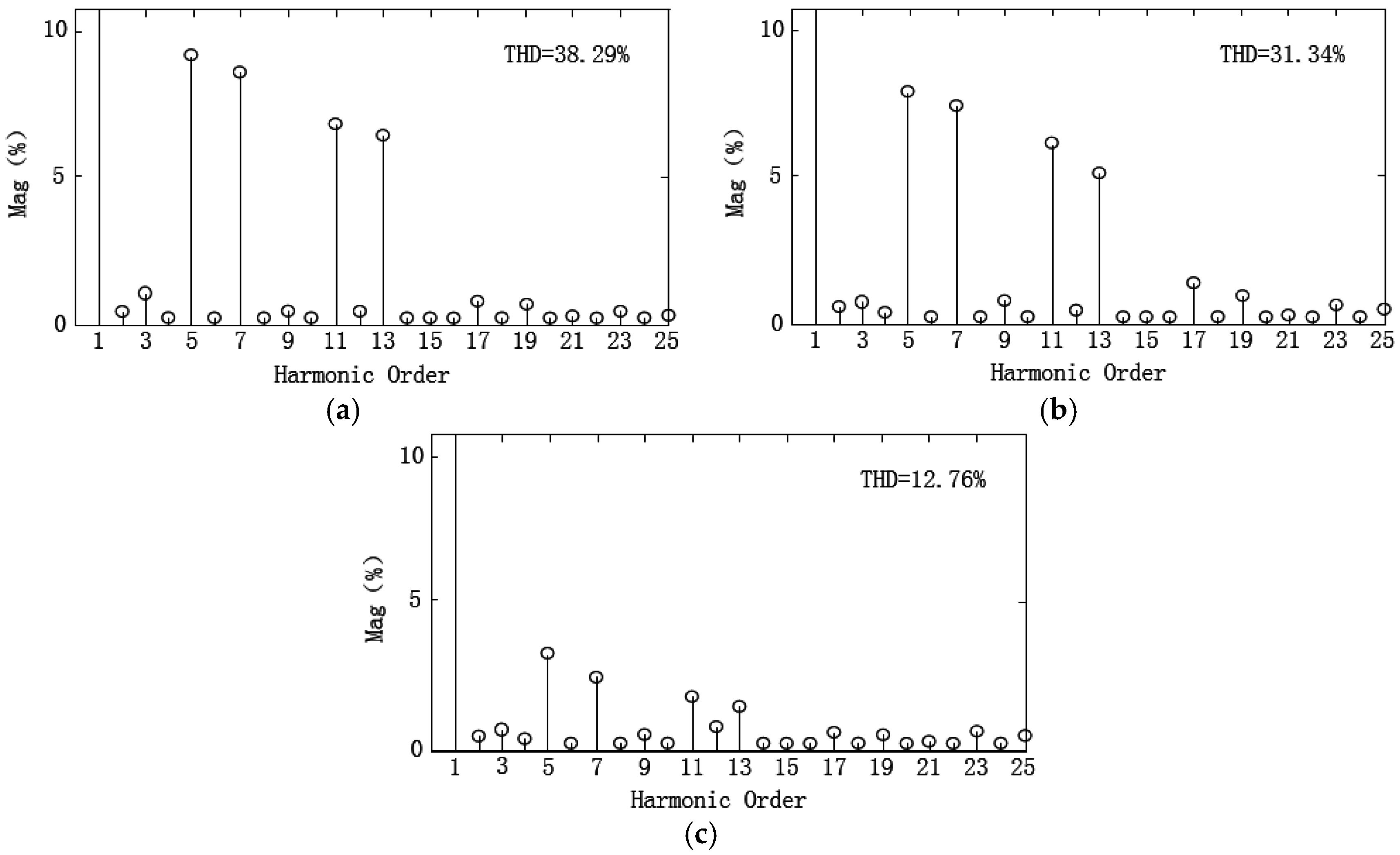
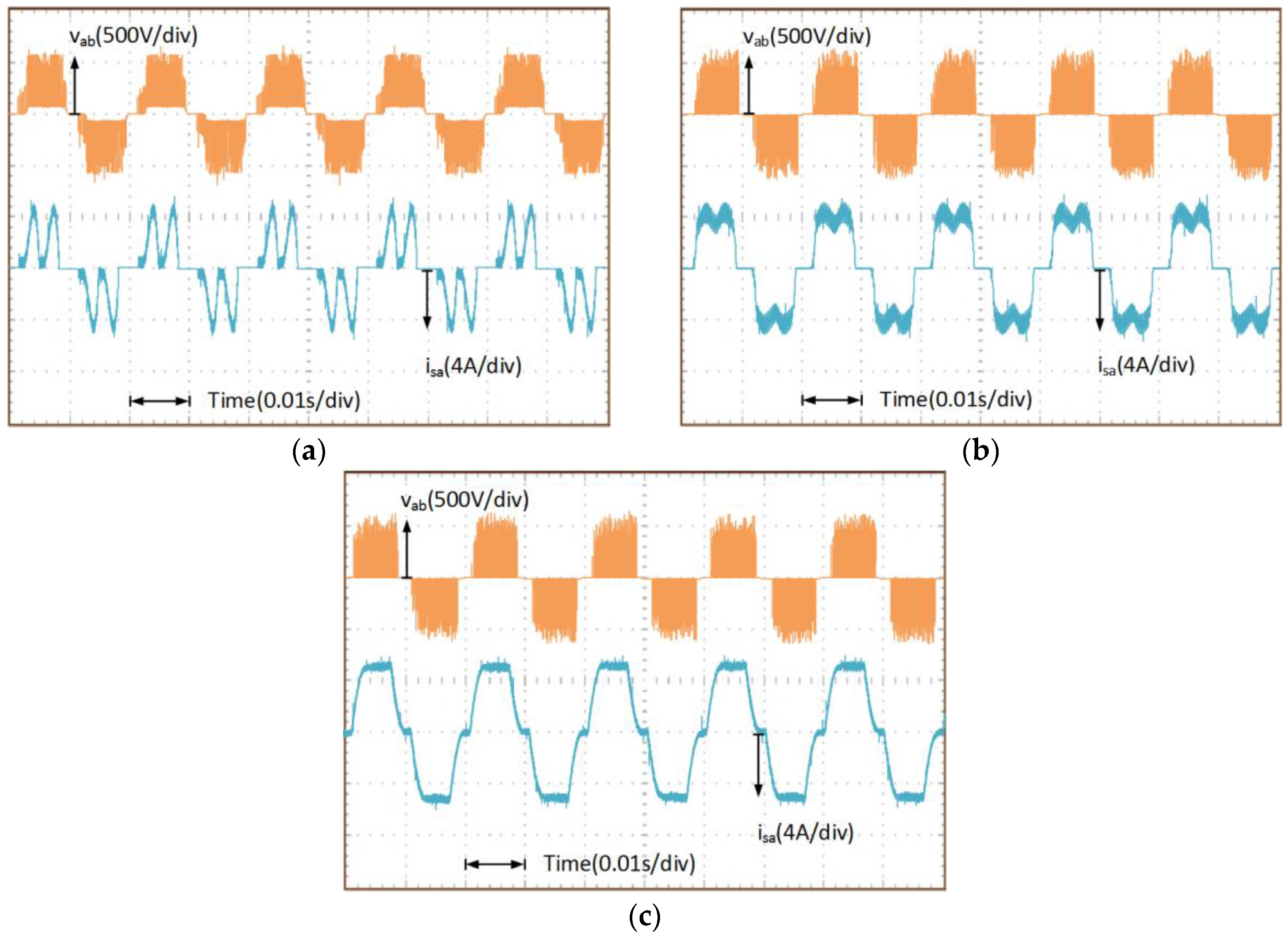
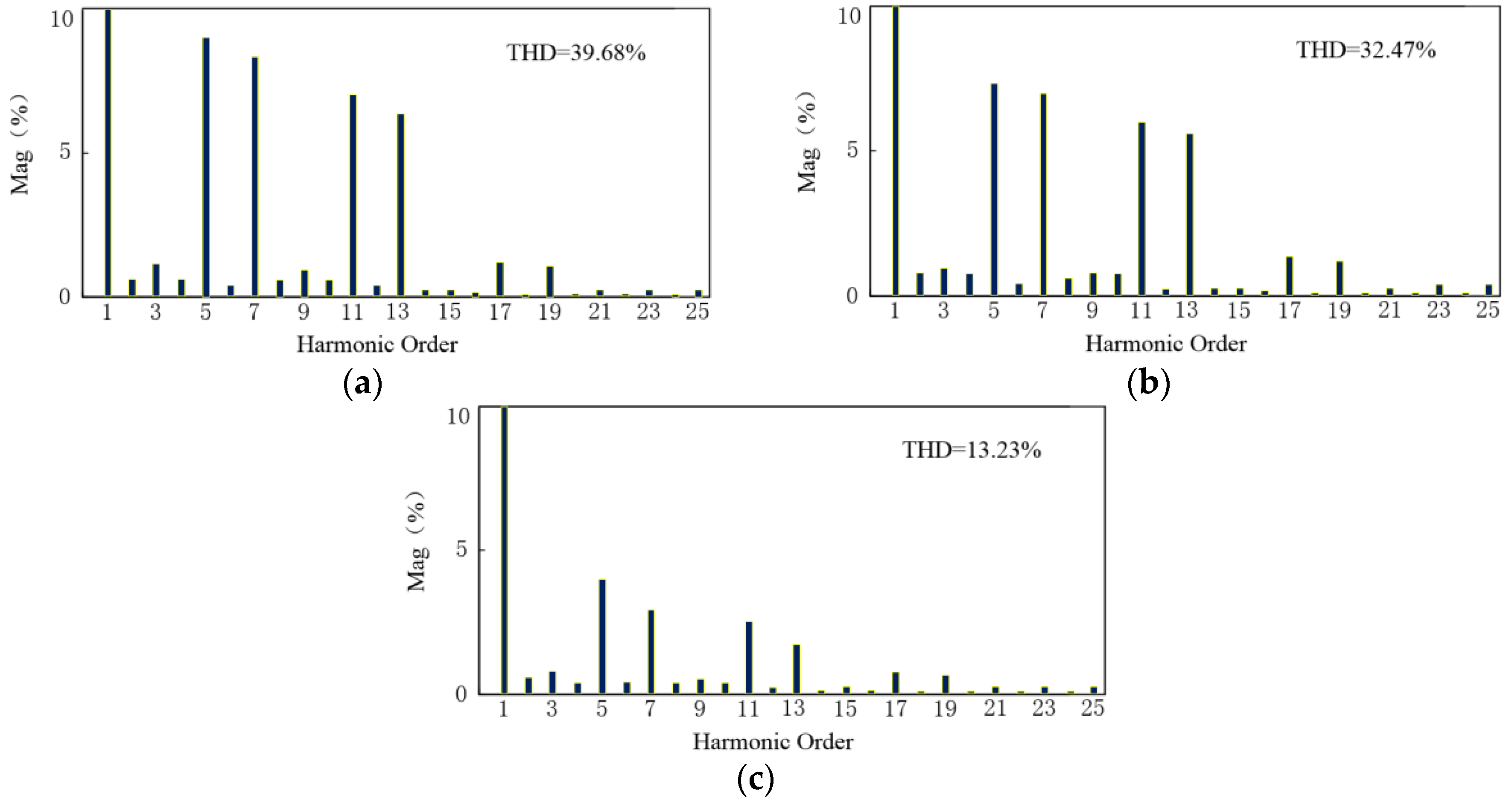
3.2. Simulation and Experimental Results

In order to verify the correctness of the theoretical analysis, a simulation model and experimental system are established with the parameters given in the following:
  • Grid line-line voltage: 380 V/50 Hz;
  • Rated power: 2.2 kW;
  • Rated speed of PMSG: 1500 RPM;
  • Winding resistance: 1.73 Ω;
  • Winding inductance: 6.5 mH;
  • Number of poles: 2;
  • Inductance of Z-source inductor: 1.5 mH;
  • Capacitance of Z-source capacitor: 900 μF;
  • Z-source capacitor voltage: 567 V.
The simulation waveforms of the grid-side in half quasi-Z-source WPGS are shown in Figure 10, where the output voltage of the half quasi-Z-source network, the half quasi-Z-source capacitor voltage, the three-phase grid-connected current, and the current of inductor L1 are included. It can be seen that the output voltage of half quasi-Z-source network is controlled at 630 V; the half quasi-Z-source capacitor voltage is controlled at 567 V; the three-phase grid-connected current is sinusoidal wave; the current of inductor L1 is relatively stable.
The proposed half quasi-Z-source WPGS is compared with the conventional Z-source WPGS and quasi-Z-source WPGS. Figure 11 shows the simulation waveforms of the stator voltage and stator current of the PMSG with Z- source inverter, quasi-Z-source inverter and half quasi-Z-source inverter. Figure 12 shows the simulation results of the stator current frequency spectrum of the PMSG with Z- source inverter, quasi-Z-source inverter and half quasi-Z-source inverter. From Figure 11a, Figure 12a and Figure 11b, Figure 12b, there are significant fifth-order, seventh-order, eleventh-order and thirteenth-order harmonics in the stator current, and the THD of the stator current is up to 38.29% and 31.34%, respectively. High harmonic distortion currents also appeared in the generator, which further reduce the efficiency and produce torque oscillations. These are the drawbacks of the conventional impedance -source WPGS. From Figure 11c and Figure 12c, it can be seen that the low-order harmonics in the stator current is obviously decreased. This low-harmonic characteristic results from the utilization of the half quasi-Z-source inverter, and the THD of the stator current is only 12.76%, which is much smaller than that in the conventional impedance -source WPGS.
An experimental platform based on a TMS320F2812 DSP has been built to verify the properties of the proposed half quasi-Z-source WPGS. An induction motor is utilized to drag a PMSG to imitate a wind turbine. Figure 13 shows a picture of the experimental system. The switching frequency is 10 kHz. The experimental results are collected by a Tektronix oscilloscope.
The experimental waveforms of the grid-side in half quasi-Z-source WPGS are shown in Figure 14, where the output voltage of half quasi-Z-source network, the half quasi-Z-source capacitor voltage, the three-phase grid-connected current, and the current of inductor L1 can be seen. The output voltage of half quasi-Z-source network and the half quasi-Z-source capacitor voltage are controlled at 630 V and 567 V, respectively. There is good steady-state performance for the three-phase grid-connected current and the current of inductor L1.
The experimental waveforms of the stator voltage and stator current of the PMSG with Z- source inverter, quasi-Z-source inverter and half quasi-Z-source inverter are shown in Figure 15.
The experimental results of the stator current frequency spectrum of the PMSG with Z-source inverter, quasi-Z-source inverter and half quasi-Z-source inverter are shown in Figure 16. It can be seen from Figure 15c and Figure 16c that there are acceptable low-order harmonics in the generator, which is due to the utilization of the half quasi-Z-source inverter, and the THD of the stator current is only 13.23%. From Figure 15a, Figure 16a and Figure 15b, Figure 16b, there are obvious fifth-order, seventh-order, eleventh-order and thirteenth-order harmonics in the stator current, and the THD of the stator current is up to 39.68% and 32.47%, respectively, which is much larger than that in the proposed half quasi-Z-source WPGS.
The experimental results are very close match to the results obtained in the simulation. With the proposed half quasi-Z-source WPGS, the THD of the stator current is dramatically reduced by 67% and 59%, compared with the Z- source WPGS and the quasi-Z-source WPGS, respectively.

4. Conclusions

In this paper, a novel half quasi-Z-source inverter for grid-connected wind power generation systems to reduce the generator stator current’s harmonic components is proposed. The derivative of three-phase stator current is analyzed in detail under the half quasi-Z-source inverter and traditional impedance-source inverter conditions. In comparison with the traditional impedance-source WPGS, the derivative of the generator stator current is only determined by the instantaneous value of the generator stator voltage under the shoot-through zero state in the proposed half quasi-Z-source WPGS. Simulation and experimental results demonstrate that with the novel H-qZSI, the THD of the stator current is significantly reduced by 67% and 59%, compared with the Z- source WPGS and the quasi-Z-source WPGS, respectively.

Acknowledgments

This work is supported from the National Natural Science foundation of China (Project No. 51377050).

Author Contributions

Yang Zhang and Shoudao Huang conceived and designed the proposed topology and control strategy. Yang Zhang performed experimental analysis, and modelling and simulation. Sijia Hu significantly contributed to the analysis of the experiment and the writing of the paper.

Conflicts of Interest

The authors declare no conflict of interest.

Abbreviations

THDTotal harmonic distortion
H-qZSIHalf quasi-Z-source inverter
EUEuropean union
ZSIZ-source inverter
q-ZSIQuasi-Z-source inverter
WPGSWind power generation system
PMSGPermanent-magnet synchronous generator
MPPTMaximum power point tracking
PWMPulse-width modulation
LVRTLow voltage ride-through
EMFElectromotive force

References

  1. European Wind Energy Association. Wind in Power, 2015 European Statistics. Available online: http://www.ewea.org/statistics/european/ (accessed on 2 May 2016).
  2. Shibata, S.; Yamada, H.; Tanaka, T.; Okamoto, Y. Reduced-capacity inrush current suppressor using a matrix converter in a wind power generation system with squirrel-cage induction machines. Energies 2016, 9, 223. [Google Scholar] [CrossRef]
  3. Wu, Q.; Peng, C. Wind power grid connected capacity prediction using LSSVM optimized by the bat algorithm. Energies 2015, 8, 14346–14360. [Google Scholar] [CrossRef]
  4. Yoon, M.; Yoon, Y.T.; Jang, G. A study on maximum wind power penetration limit in island power system considering high-voltage direct current interconnections. Energies 2015, 8, 14244–14259. [Google Scholar] [CrossRef]
  5. Zhao, H.R.; Guo, S.; Li, H.Z. Economic impact assessment of wind power integration: A quasi-public goods property perspective. Energies 2015, 8, 8749–8774. [Google Scholar] [CrossRef]
  6. Peng, F.Z. Z-source inverter. IEEE Trans. Ind. Appl. 2003, 39, 504–510. [Google Scholar] [CrossRef]
  7. Vijay, V.; Shruthi, K.J.; Kini, P.G.; Viswanatha, C.; Bhatt, M.S. Modified Z-source inverter based three phase induction motor drive for solar PV applications. In Proceedings of the 2014 International Conference on Power Signals Control and Computations (EPSCICON), Thrissur, India, 6–11 January 2014.
  8. Feyzi, M.R.; Kh, S.A.; Niapour, M.; Danyali, S.; Shafiei, M. Supplying a brushless DC motor by Z-source PV power inverter with FLC-IC MPPT by DTC drive. In Proceedings of the 2010 International Conference on Electrical Machines and Systems (ICEMS), Incheon, Korea, 10–13 October 2010.
  9. Niapoor, S.A.; Danyali, S.; Sharifian, M.B. PV power system based MPPT Z-source inverter to supply a sensorless BLDC motor. In Proceedings of the IEEE Power Electronic & Drive Systems & Technologies Conference (PEDSTC), Tehran, Iran, 17–18 February 2010.
  10. Hosseini, S.H.; Nejabatkhah, F.; Niapoor, S.A.; Danyali, S. Supplying a brushless dc motor by z-source PV power inverter with FL-IC MPPT. In Proceedings of the 2010 International Conference on Green Circuits and Systems (ICGCS), Shanghai, China, 21–23 June 2010.
  11. Kalaiarasi, N.; Paramasivam, S.; Kuntu, S. Comparison of Z-source inverter with DC-DC boost converter fed VSI for PV applications. In Proceedings of the 2014 IEEE 2nd International Conference on Electrical Energy Systems (ICEES), Chennai, India, 7–9 January 2014.
  12. Qiu, Y.N.; Jiang, H.X.; Feng, Y.H.; Cao, M.N.; Zhao, Y.; Li, D. A new fault diagnosis algorithm for PMSG wind turbine power converters under variable wind speed conditions. Energies 2016, 9, 548. [Google Scholar] [CrossRef]
  13. Lin, C.H. Wind turbine driving a PM synchronous generator using novel recurrent chebyshev neural network control with the ideal learning rate. Energies 2016, 9, 441. [Google Scholar] [CrossRef]
  14. Wang, D.; Liu, C.R.; Li, G. An optimal integrated control scheme for permanent magnet synchronous generator-based wind turbines under asymmetrical grid fault conditions. Energies 2016, 9, 307. [Google Scholar] [CrossRef]
  15. Yu, Y.F.; Zhang, Q.F.; Liang, B.; Liu, X.F.; Cui, S.M. Analysis of a single-phase Z-source inverter for battery discharging in vehicle to grid applications. Energies 2011, 4, 2224–2235. [Google Scholar] [CrossRef]
  16. Ahmed, T.; Soon, T.K.; Mekhilef, S. A single phase doubly grounded semi-Z-source inverter for photovoltaic (PV) systems with maximum power point tracking (MPPT). Energies 2014, 7, 3618–3641. [Google Scholar] [CrossRef]
  17. Yu, K.; Xiong, B.; Zhao, J.Y. A comprehensive study of space vector pulse-width modulation technique for three-phase ZSIs. Int. J. Circuit Theory Appl. 2016, 44, 364–381. [Google Scholar] [CrossRef]
  18. Yu, K.; Zhao, J.Y. Space vector pulse-width modulation for single-phase full-bridge Z-source inverter. Int. J. Circuit Theory Appl. 2015, 43, 374–389. [Google Scholar] [CrossRef]
  19. Anderson, J.; Peng, F.Z. Four quasi-Z-source inverters. In Proceedings of the 39th IEEE Annual Power Electronics Specialists Conference, Rhodes, Greece, 15–19 June 2008.
  20. Vinnikov, D.; Roasto, I. Quasi-Z-source-based isolated DC/DC converters for distributed power generation. IEEE Trans. Ind. Electron. 2011, 58, 192–201. [Google Scholar] [CrossRef]
  21. Sun, D.; Ge, B.; Liang, W.; Rub, H.; Peng, F.Z. An energy stored quasi-Z-source cascade multilevel inverter-based photovoltaic power generation system. IEEE Trans. Ind. Electron. 2015, 62, 5458–5467. [Google Scholar] [CrossRef]
  22. Liu, Y.; Ge, B.; Rub, H.; Peng, F.Z. An effective control method for three-phase quasi-Z-source cascaded multilevel inverter based grid-tie photovoltaic power system. IEEE Trans. Ind. Electron. 2014, 61, 6794–6802. [Google Scholar] [CrossRef]
  23. Zhou, Y.; Li, H. A single-phase PV quasi-Z-source inverter with reduced capacitance using modified modulation and double-frequency ripple suppression control. IEEE Trans. Power Electron. 2016, 31, 2166–2173. [Google Scholar] [CrossRef]
  24. Supatti, U.; Peng, F.Z. Z-source inverter based wind power generation system. In Proceedings of the 2008 IEEE International Conference on Sustainable Energy Technologies, Singapore, 24–27 November 2008.
  25. Dehghan, S.M.; Mohamadian, M.; Varjani, A.Y. A New Variable-Speed Wind Energy Conversion System Using Permanent-Magnet Synchronous Generator and Z-Source Inverter. IEEE Trans. Energy Convers. 2009, 24, 714–724. [Google Scholar] [CrossRef]
  26. Ramasamy, B.K.; Palaniappan, A.; Yakoh, S.M. Direct-drive low-speed wind energy conversion system incorporating axial-type permanent magnet generator and Z-source inverter with sensorless maximum power point tracking controller. IET Renew. Power Gener. 2013, 7, 284–295. [Google Scholar] [CrossRef]
  27. Huang, S.D.; Zhang, Y.; Shuai, Z.K. Capacitor voltage ripple suppression for z-source wind energy conversion system. Energies 2016, 9, 56. [Google Scholar] [CrossRef]
  28. Qu, K.Q.; Zhou, H.; Xing, Y.H. A LVRT method for wind power pmsg system with Z-source inverter. In Proceedings of the IEEE Power Engineering and Automation Conference (PEAM), Wuhan, China, 8–9 September 2011.
  29. Liu, Y.S.; Ge, B.M.; Peng, F.Z. Quasi-Z-source inverter based PMSG wind power generation system. In Proceedings of the IEEE Energy Conversion Congress and Exposition (ECCE), Phoenix, AZ, USA, 17–22 September 2011.
  30. Hussien, A.; Taha, M.; Mahgoub, O.A. Design and control of a quasi-Z-source inverter based for wind power generation using PMSG. In Proceedings of the 2015 IEEE 15th International Conference on Environment and Electrical Engineering (EEEIC), Rome, Italy, 10–13 June 2015.
  31. Maity, T.; Prasad, H.; Babu, V.R. Study of the suitability of recently proposed Quasi Z-source Inverter for wind power conversion. In Proceedings of the 2014 International Conference on Renewable Energy Research and Application (ICRERA), Milwaukee, WI, USA, 19–22 October 2014.
  32. Sun, Q.; Wang, Y.Y. On control strategy of Z-source inverter for grid integration of direct-driven wind power generator. In Proceedings of the IEEE Control Conference (CCC), Hefei, China, 25–27 July 2012.
  33. Jegatheeswaran, R.; Rajesh, R. Variable speed wind energy conversion system using PMSG & Z-source inverter. In Proceedings of the 2015 International Conference on Innovations in Information, Embedded and Communication Systems (ICIIECS), Coimbatore, India, 19–20 March 2015.
  34. Bharanikumar, R.; Senthilkumar, R.; Yazhini, A.C.; Kumar, A.N. Impedance source inverter for wind turbine driven permanent magnet generator. In Proceedings of the Power System Technology and IEEE Power India Conference, New Delhi, India, 12–15 October 2008.
Figure 1. The topology of a half quasi-Z-source inverter.
Energies 09 00770 g001
Figure 2. The equivalent circuit of the half quasi-Z-source inverter in the shoot-through zero state.
Energies 09 00770 g002
Figure 3. The equivalent circuit of the half quasi-Z-source in the non-shoot-through zero state.
Energies 09 00770 g003
Figure 4. The control system of three-phase half quasi-Z-source grid-connected inverter.
Energies 09 00770 g004
Figure 5. The equivalent circuit of the Z-source wind power generation system in the shoot-through zero state.
Energies 09 00770 g005
Figure 6. Six possible conduction intervals in half cycle.
Energies 09 00770 g006
Figure 7. The phase current waveforms in a switching cycle during sector one.
Energies 09 00770 g007
Figure 8. The equivalent circuit of half quasi-Z-source inverter (H-qZSI) wind power generation system in each modes. (a) Mode 1; (b) Mode 2; (c) Mode 3.
Energies 09 00770 g008
Figure 9. The equivalent circuit of quasi-Z-source inverter (qZSI) wind power generation system in each modes: (a) Mode 1; (b) Mode 2; (c) Mode 3.
Energies 09 00770 g009
Figure 10. Simulation waveforms of the grid-side in half quasi-Z-source wind power generation system (WPGS).
Energies 09 00770 g010
Figure 11. Simulation waveforms of the stator voltage and stator current of the PMSG with different impedance-source topologies. (a) With Z- source inverter; (b) With quasi-Z-source inverter; (c) With half quasi-Z-source inverter.
Energies 09 00770 g011
Figure 12. Simulation results of the stator current frequency spectrum of the PMSG with different impedance-source topologies. (a) With Z-source inverter; (b) With quasi-Z-source inverter; (c) With half quasi-Z-source inverter.
Energies 09 00770 g012
Figure 13. A picture of the experimental system.
Energies 09 00770 g013
Figure 14. Experimental waveforms of the grid-side in half quasi-Z-source WPGS.
Energies 09 00770 g014
Figure 15. Experimental waveforms of the stator voltage and stator current of the PMSG with different impedance-source topologies. (a) With Z- source inverter; (b) With quasi-Z-source inverter; (c) With half quasi-Z-source inverter.
Energies 09 00770 g015
Figure 16. Experimental results of the stator current frequency spectrum of the PMSG with different impedance-source topologies. (a) With Z-source inverter; (b) With quasi-Z-source inverter; (c) With half quasi-Z-source inverter.
Energies 09 00770 g016

