Article

Performance Characteristics of a Modularized and Integrated PTC Heating System for an Electric Vehicle

1
Green Car Power System R&D Division, Korea Automotive Technology Institute, 74 Yongjung-Ri, Pungse-Myun, Dongnam-Gu, Chonan-Si, Chungnam 330-912, Korea
2
Donga High Tech Company, Dongtangiheung-Road, Dongtan-Myeon, Hwaseong-Si, Gyunggi-Do 445-813, Korea
3
School of Mechanical Engineering, Yeungnam University, 280 Daehak-Ro, Gyeongsan, Gyeongbuk 712-749, Korea
*
Author to whom correspondence should be addressed.
Energies 2016, 9(1), 18; https://doi.org/10.3390/en9010018
Submission received: 2 November 2015 / Revised: 10 December 2015 / Accepted: 23 December 2015 / Published: 28 December 2015
(This article belongs to the Special Issue Advanced Heating and Cooling Techniques)

Abstract

:
A modularized positive temperature coefficient heating system has controller-integrated heater modules. Such a heating system that uses a high-voltage power of 330 V was developed in the present study for use in electric vehicles. Four heater modules and one controller with an input power of 5.6 kW were integrated in the modularized system, which was designed for improved heating power density and light weight compared to the conventional heating system, in which the controller is separated. We experimentally investigated the performance characteristics, namely, the heating capacity, energy efficiency, and pressure drop, of a prototype of the developed heating system and found it to have satisfactory performance. The findings of this study will contribute to the development of heating systems for electric vehicles.

1. Introduction

There has been a global acceleration in the development of high-efficiency and environmentally friendly vehicles with the goal of solving climate problems such as global warming and addressing the issue of energy depletion. In particular, efforts are being made to increase the use of electric vehicles. Unlike conventional internal combustion engine vehicles, electric vehicles have no gas emissions and their high energy efficiency also reduces considerably the generation of waste heat. An operation strategy for optimal energy management is thus more important in electric vehicles [1,2,3,4]. There is particularly the need to develop a new heating system for indoor heating in winter as a replacement for engine waste heat, which is used in conventional vehicles.
Because the heating system of an electric vehicle consumes the largest proportion of energy, excluding the actual running of the vehicle, high-efficiency heat pumps have been developed and used to increase the driving range of some vehicles [5,6,7]. A positive temperature coefficient (PTC) electric heater offers an even more realistic alternative owing to its simple structure and rapid response [8,9]. However, the use of a high-voltage air-heating type of this electric heater, which is mounted on the heating, ventilation, and air conditioning system (HVAC) of the vehicle, requires the development of a heating system with a highly modularized and integrated structure.
Unlike a low-voltage electric heater with a heating capacity of about 1 kW, such as that used as an auxiliary heater in a conventional internal combustion engine [10,11], the capacity of the main heating system of an electric vehicle is generally 5 kW or higher. A high-voltage PTC heater (330 V) can supply the same amount of power with a lower current than a low-voltage PTC heater (13.5 V). Further, this results in a reduction in the weight of the power supply cable and an increase in energy efficiency. However, because the system is operated by a high-voltage power supply, the stability of its structure and control technology is essential [12]. Moreover, enhancement of the driving range requires improvement of the power density by increasing the efficiency and decreasing the weight of the heating system.
A ceramic PTC thermistor is characterized by fixed-temperature heat generation and is safe for autonomous temperature control within a given limit. It is thus very suitable for use as a heat source for the indoor electric heater of a vehicle. However, the fabrication of the heating element of a high-voltage electric heater requires the development of a sputtering deposition technology for more uniform and denser surface coating of the electrode of a ceramic heating element compared to that achieved by the conventional screen printing process [13].
In the present study, we fabricated a prototype of a high-voltage heating system for electric vehicles. The system has a controller-integrated heater module design and was experimentally tested and analyzed to determine its heating performance and reliability.

2. Design and Analysis

2.1. Heating System Design

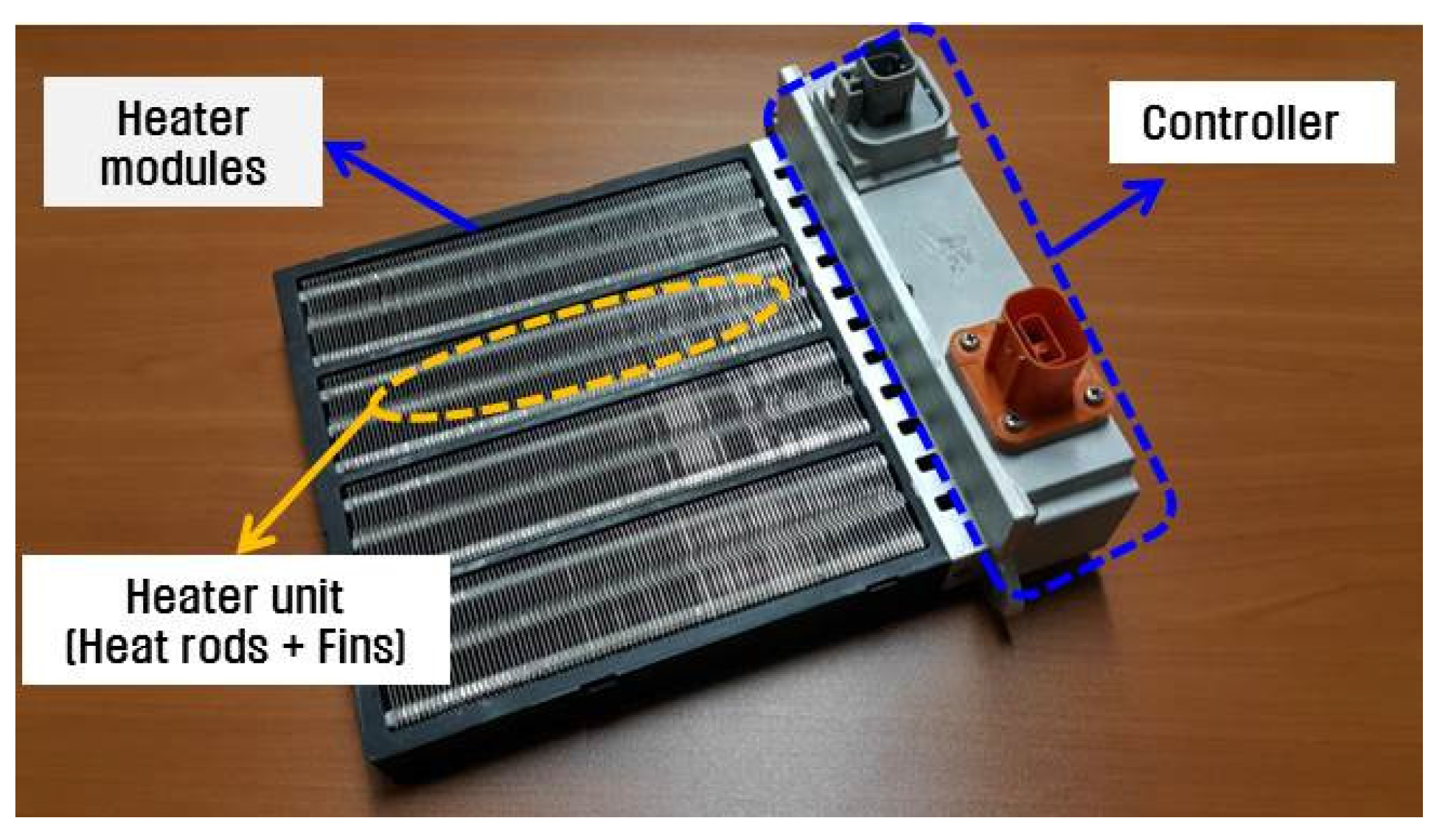
We designed and fabricated a high-voltage modularized and integrated heating system. The system contains four heater modules—with each unit comprising heating rods and radiation fins—and an integrated controller, which is used to regulate the power input and operate the heater. The system is shown in Figure 1 and the specifications are presented in Table 1. The main feature of the system is its proactive production response with respect to the heating capacity, which is afforded by the modular design. Compared to a conventional heating system, in which the heater and controller are separately configured, the developed system is 20% lighter. It also has the advantage of less high-voltage cable work between the controller and heater for its installation inside a vehicle.
Figure 1. Modularized and integrated high-voltage heating system.
Energies 09 00018 g001
Table 1. Specifications of the high-voltage heating system.
ParameterValue
Core size (mm3)200 × 210 × 28
Weight (g)2200
Input voltage (V)330
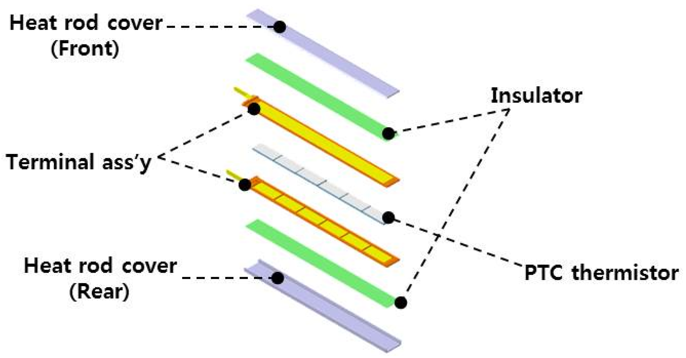
Each of the heating rods, which are core components of each heater module unit, consists of a PTC thermistor, terminal assembly, insulator, and heat rod cover, as shown in 
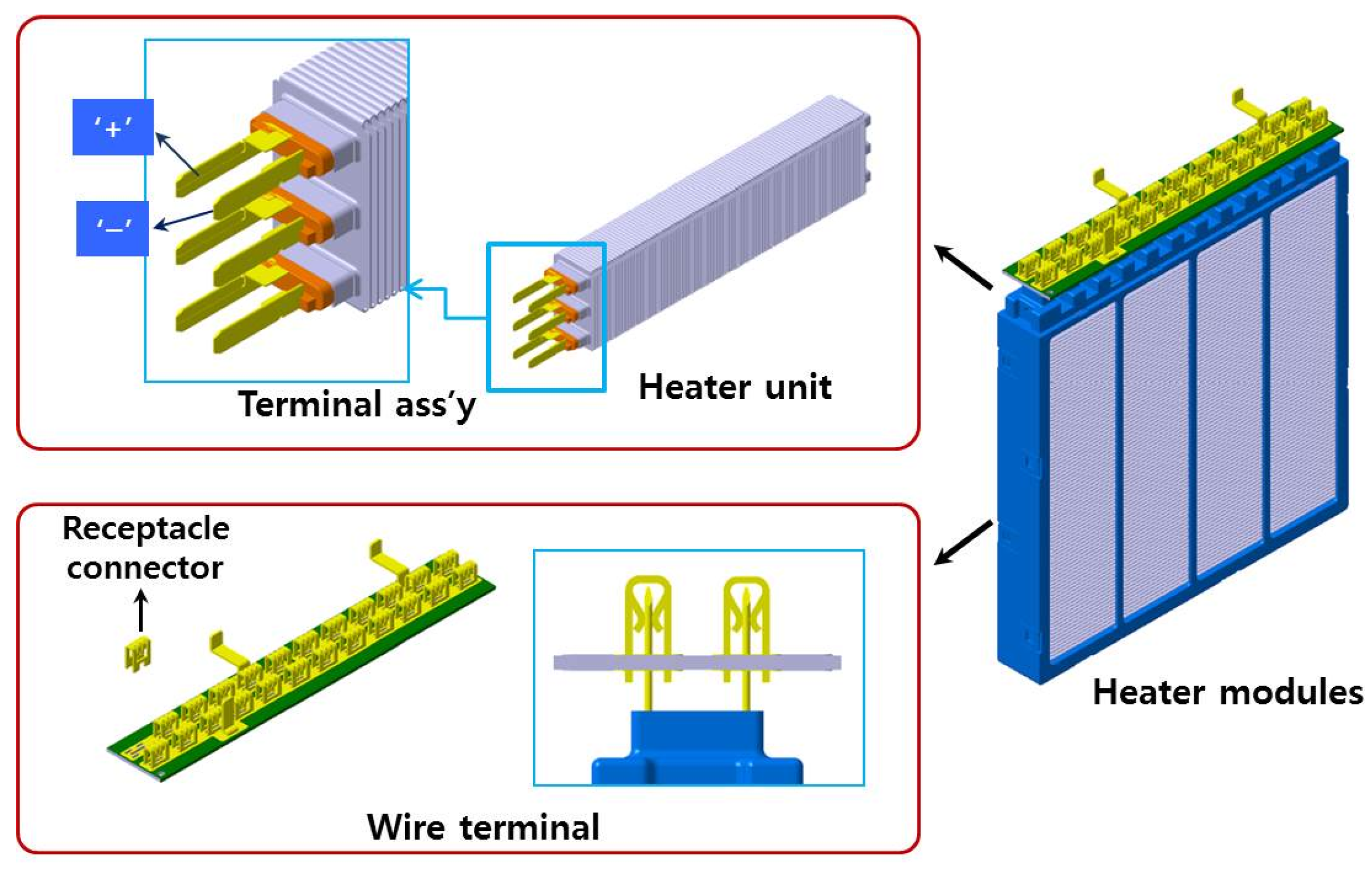
Figure 2. The configuration of the power terminal structure is based on the shape of the heating rod and fins, as shown in Figure 3. The adopted structure improves the insulation and water resistance of the external surface of the heater, and the positive and negative terminals of the power supply are inserted into the cover of the heating rod. To further improve the assembly and enable smooth connection to the controller, receptacle connectors are employed in the power supply section of the heater module.
Figure 2. Schematic diagram of a heating rod.
Energies 09 00018 g002
Figure 3. Schematic diagram of the heating unit and modules.
Energies 09 00018 g003
The heater module unit directly affects the heating performance of the system. Therefore, to achieve higher performance, the heating rods and fins of the heater modules were varied as indicated in Table 2 and Table 3, respectively, and the corresponding performances of the heating system, which contained four heater modules, compared. The heating performance of a heater module was evaluated based on the maximum temperature of the PTC thermistor and the conductivity of the insulator. The fins served as heat exchangers with the environment, and the heater module performance was also examined for various thickness and shapes of the fins, as indicated in Table 3.
Table 2. Experimental results of the heater module performance for varying properties of heating rod.
Varying Properties of Heating RodHeating Capacity of Heater Modules (kW)
Maximum temperature of the PTC thermistor (°C) @ plate fin thickness of 0.3 mm1605.1
1705.2
1805.4
Conductivity of the insulator (W/m·K) @ plate fin thickness of 0.4 mm1.24.9
1.55.0
3.05.4
Notes: Standard condition: maximum PTC thermistor temperature of 170 °C and insulator conductivity of 3.0 W/m·K.
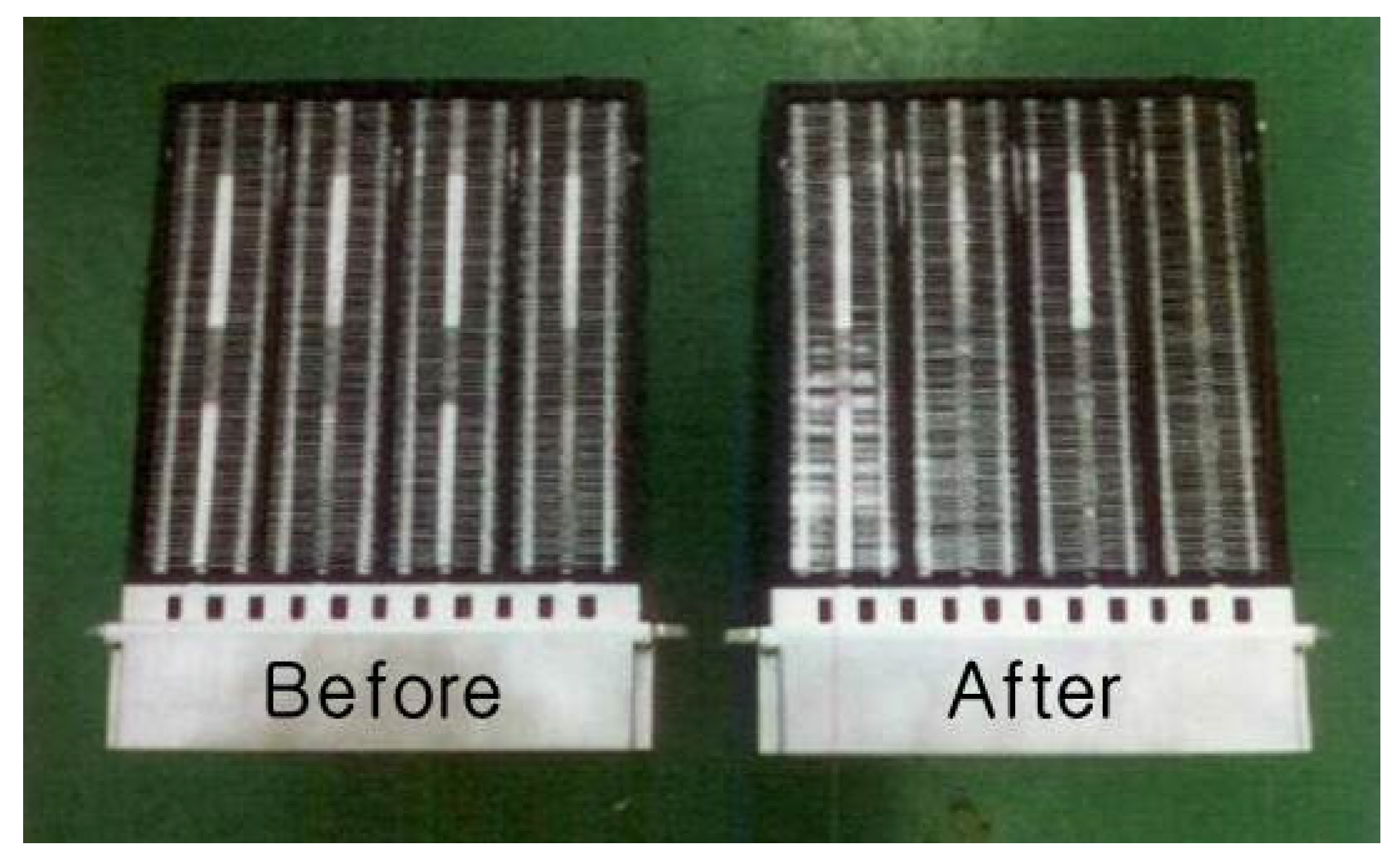
The radiation fins of the PTC heater module are the key parts of the heating system that radiate heat directly into the air. The design parameters of a fin are important for achieving lightweight and high PTC heater energy efficiency. As shown in Table 3, heater modules using 0.3- and 0.4-mm-thick comparison models, with the shape fixed as plate, yielded heating capacities of 5.2 and 5.4 kW, respectively. The heat outputs of the heater modules using plate and embossed fin models, with thickness fixed at 0.3 mm, were 5.2 and 5.4 kW, respectively. Therefore, the optimized design parameter for a radiation fin for the PTC heater was determined to be a thickness of 0.3 m, given the advantage of the 0.3 m model over the 0.4 m model in the tradeoff between weight and capacity, and the embossed type because of the turbulent effect of the emboss.
Table 3. Experimental results of the heater module performance for varying fin geometry.
Varying Fin GeometryHeating Capacity of Heater Modules (kW)
Thickness of plate fin (mm)0.35.2
0.45.4
Shape of fin @ fin thickness of 0.3 mm Energies 09 00018 i001 Plate5.2
Energies 09 00018 i002 Emboss5.4
Notes: Standard condition: maximum PTC thermistor temperature of 170 °C and insulator conductivity of 3.0 W/m·K.
The printed circuit board (PCB) of the heating system’s controller and other components were configured as shown in Figure 4. The specifications are given in Table 4. Compared to the conventional separated-type heating system, the integrated structure of the developed system and the arrangement of its components afforded compactness.
Figure 4. PCB of the controller and other components of the heating system.
Energies 09 00018 g004
Table 4. Specifications of the controller of the high-voltage heating system.
ItemSpecification
Operating voltage (V)High voltage: 220–460/Low voltage: 9–16
CommunicationCAN 2.0
OutputPWM (Pulse Width Modulation)
ProtectionOver current protection
Over/under voltage protection
Command fail
Interlock detection
Soft start
Maximum power consumption

2.2. Heater Module Analysis

Assuming a symmetrical shape with respect to the PTC heater cross-section, we applied a 1/16 model and ignored the heat radiation error stemming from the power source terminal. The boundary conditions used to analyze the heating performance of the PTC heater consisted of an inlet air flow of 500 kg/h, inlet air temperature of 0 °C, and heating capacity of the PTC element of 312.2 W. The heat value of the PTC element was calculated by applying a PTC heater module heating capacity of 5 kW to the analysis model. A thermal analysis of the heater was also performed by substituting the property values for each component into the model. The number of mesh is about ten million and the computational time required to produce a converged solution was about 1 or 2 days on average. The analysis program that was used in this study utilizes the grid-quality check method, and its analysis involves a method that checks the convergence for each iteration, confirming that the grid independency is highly reliable.
The mass, momentum, and energy conservation equations were used as the governing equations for the simulation of the heater. The turbulence model was used to calculate the turbulent flow with constants obtained via empirical and theoretical methods. The modified production (MP) k-ε equation known as the Kato-Launder modification was used for the turbulence model [14]. The heat flow analysis was performed using SC-tetra built on a node-based finite-volume discretization method, a commercial analysis program [
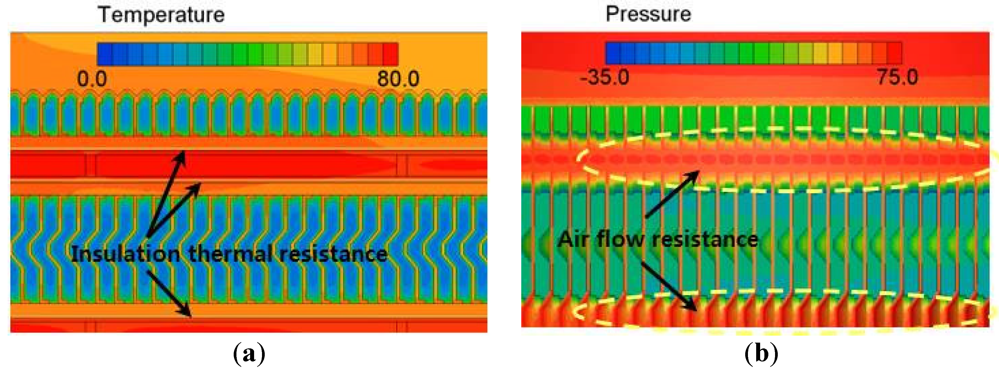
15], and the analysis results were organized with respect to the heater’s temperature distribution using a pressure drop to below a value corresponding to an air flow of 500 kg/h, which was the maximum flow of the blower. The cross-sectional temperature distribution around the heating rods and fins of the PTC heater is shown in Figure 5a. The distribution reflects the pertinent air flow and is shown in a manner that enables comparison of the different heat transfer paths from the PTC element to the fins. In the heat transfer path from the PTC element surface to the fins, the heat resistance of the radiation pad, which serves as an insulator, accounted for about 75% of the total heat resistance. Figure 5b shows the pressure distribution in the fin at the same position of the temperature distribution shown in Figure 5a. A relatively high flow resistance was observed at the point where the heat rods and fins of the PTC heater curve. The temperature and pressure of each component of the PTC heater determined by the analysis can be used to improve the fin design.
Figure 5. Temperature and pressure distribution of the high-voltage PTC heater modules. (a) Temperature distribution (°C); (b) Pressure distribution (Pa).
Energies 09 00018 g005

2.3. Heat Interference Analysis of the Controller

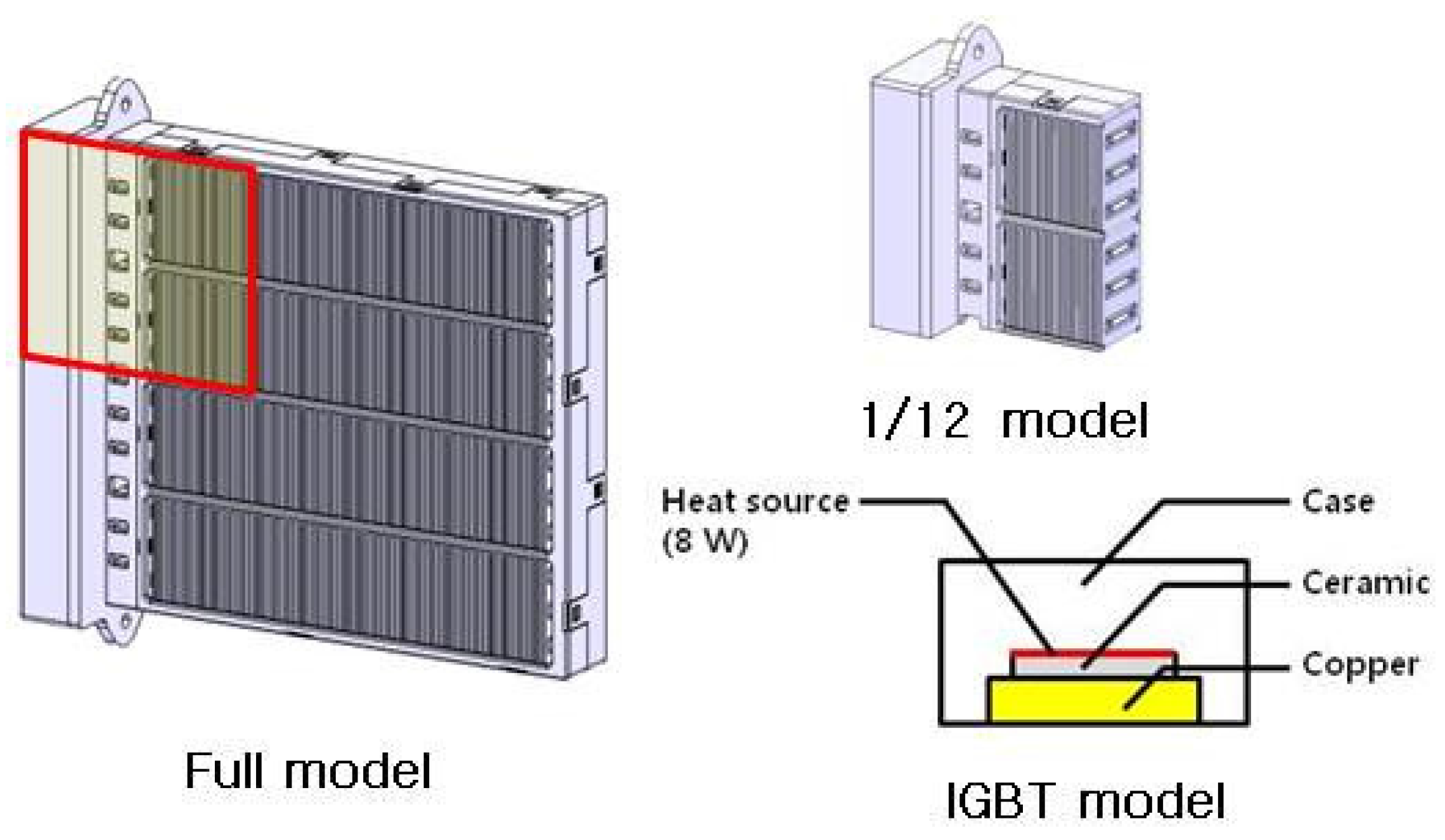
The integration of the controller and the heater modules, which are conventionally separated, causes the radiation performance of the controller to decline due to heat interference with the heater in the limited space. By a heat flow analysis, we considered possible design alternatives for addressing this issue. The employed analysis model of the controller-integrated PTC heating system is shown in Figure 6. The model contains an insulated gate bipolar mode transistor (IGBT), which serves as a heat source and is a core component of the controller. It was developed using a scale of 1/12. The flow region of the analysis was set to ensure flux uniformity.
The boundary conditions were divided into basic and severe conditions as indicated in Table 5 to compare the radiation performance of the controller with respect to the operation condition of the system. The analysis was performed by switching between operation and non-operation of the heater and various flow conditions of the blower. The basic flow condition was 300 kg/h and the severe condition corresponded to reduction of the air flow by about 2/3, which constitutes a severe operation environment for the controller in a real vehicle environment [16]. The physical property value for each component including the IGBT was used for the analysis.
Figure 6. Analysis model of the heat interference with the controller.
Energies 09 00018 g006
Table 5. Boundary conditions for heat flow analysis of the controller-integrated high-voltage PTC heating system.
Operating ConditionHeater Not OperatedHeater Operated
Basic ConditionsBasic ConditionsSevere Conditions
Inlet air flow (kg/h)35.9 (300 kg/h at full mode)12.0 (100 kg/h at full mode)
Air temperature (°C)-0
Heat value of IGBT (W)-8
Heat value of PTC (W)0416.7 (Heating capacity of 5 kW)250 (Heating capacity of 3 kW)
Table 6 summarizes the temperatures attained by the components as determined by the analysis. The temperature of the IGBT under operation conditions without the heater was determined to be about 59.6 °C, while the operation of the heater increased it to about 77.9 °C. Under the severe condition involving decreased air flow, the temperature increased to a maximum of 101.4 °C. Because this was within the allowed range for the controller, the radiation design was determined to be appropriate.
Table 6. Results of the heat flow analysis of the controller-integrated high-voltage PTC heating system.
ComponentHeater Not OperatedHeater Operated
Basic ConditionBasic ConditionSevere Condition
IGBT (°C)59.577.9101.4
PTC element (°C)-92.8113.2
Radiation fin (°C)-80.0105.6
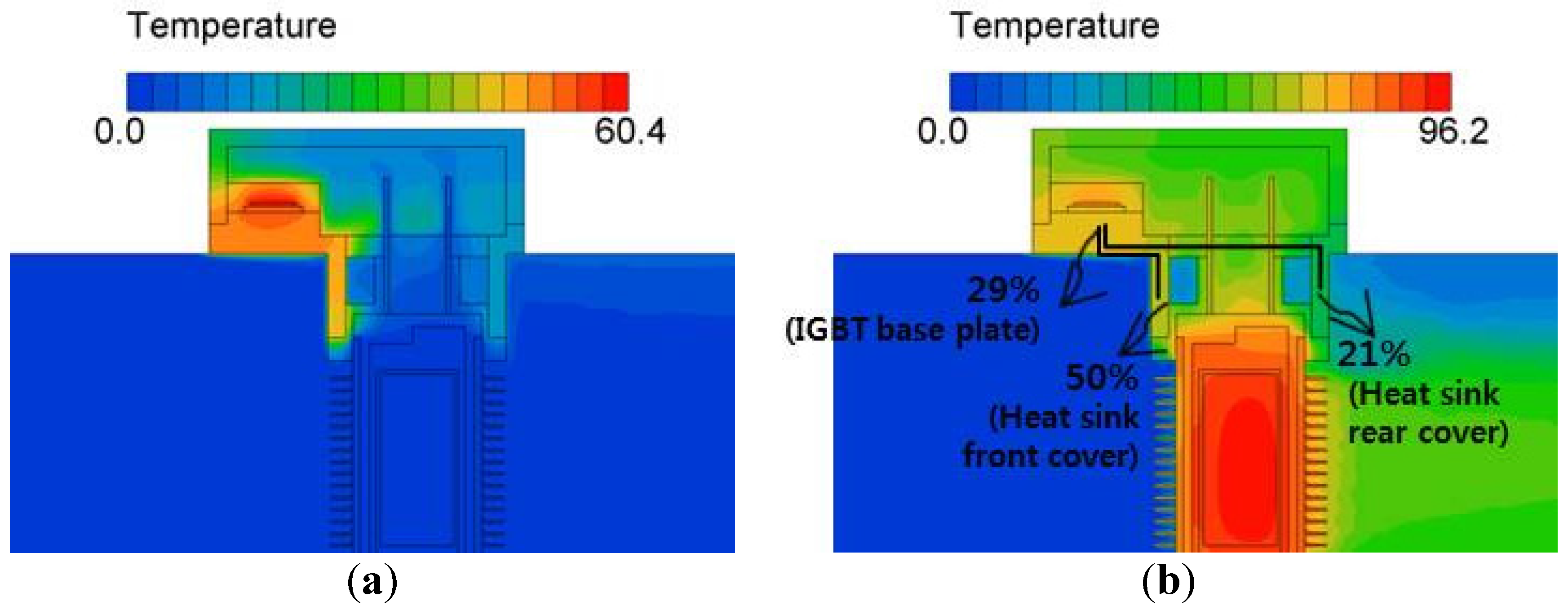
Figure 7 compares the cross-sectional temperature distributions of the PTC heater with and without operation of the heat source under the basic operation condition, and also quantitatively shows the heat transfer paths through the IGBT components. Radiation apparently constitutes a considerable portion of the heat produced in the IGBT; about 71% of the heat is transferred to the controller housing cover, which functions as a heat sink. 
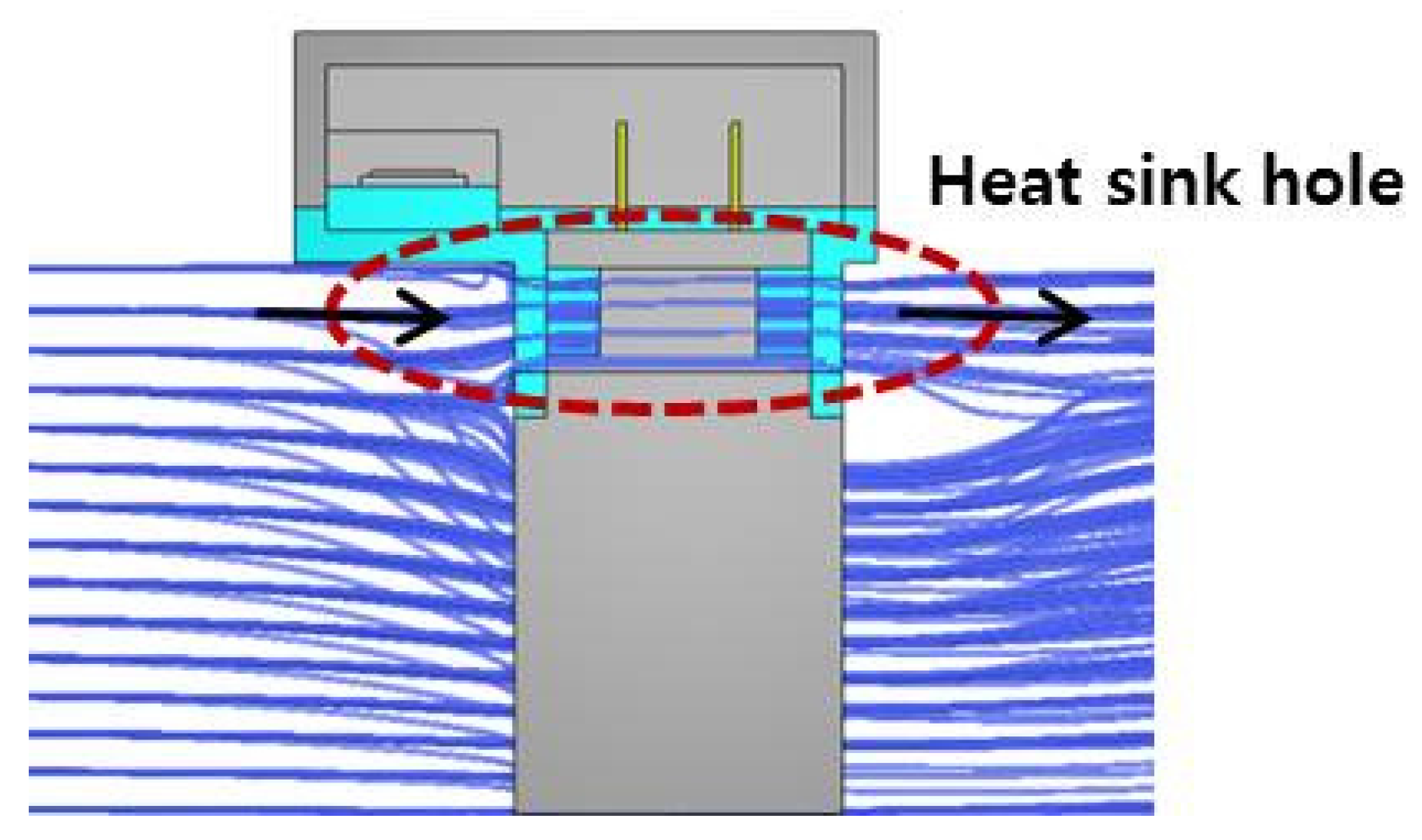
Figure 8 shows the air flow line through the heat sink of the controller. It was observed that about 5% of the total air flow into the radiator entered the cooling hole of the heat sink. This flow proportion indicates a correlation between the heating performance of the system and the heat interference with the controller.
Figure 7. Comparison of the temperature distributions in the PTC heater under the basic condition with and without operation of the heater (°C). (a) Without operation of the heater; (b) With operation of the heater.
Energies 09 00018 g007
Figure 8. Flow line at the heat sink hole of the heating system controller.
Energies 09 00018 g008

3. Performance and Reliability Experiments

3.1. Test Facility and Method

A wind tunnel device was configured inside the constant-temperature chamber, as shown in Figure 9a, to measure the heating capacity, efficiency, and pressure drop of the high-voltage heating system. A T-type thermocouple and twenty four-point thermocouples with a resolution of ±0.1 °C were used to measure the inlet and outlet air temperatures of the wind tunnel device. All the temperature and pressure measurements were collected by a Gantner data logger. The experimental conditions for measuring the heating performance of the vehicle heating system comprised an input power voltage of 330 V, inlet air temperature of 0 °C, and inlet air flow rate of 300 kg/h. This was used to replicate the air flow from the HVAC system blower of a vehicle under outdoor winter temperature conditions.
To assess the reliability of the high-voltage heating system, we evaluated the heating performance after conducting impact and dust tests. The target was to achieve less than 10% change in the heating performance. The impact and dust test conditions are given in Table 7 and Table 8, respectively.
Figure 9. Schematic diagram of the test facility and prototype heating system used to evaluate the heating performance. (a) Schematic diagram of the test facility; (b) Installation of the prototype heating system.
Energies 09 00018 g009
Table 7. Impact test conditions.
Waveform TypeHalf Sine
Peak acceleration (g)100
Pulse duration (ms)6
Impact directionX, Y, Z
Number of impacts±10
Table 8. Dust test conditions.
Test temperature (°C)20
Dust typePortland cement
Concentration (mg/m3)3000
Humidity (%)45–85
Test timeDust spreading time5 s
Unspreading time (pause time)15 min
Repetition time8 h

3.2. Performance and Reliability Results

The air-side heat transfer, power consumption, and pressure drop of the developed high-voltage heating system were measured using four final prototypes and the results were used to evaluate the heating performances and efficiencies of the systems. Efficiency is the ratio of the heating capacity to the power consumption of the system, and is calculated using Equation (1). Table 9 summarizes the results for the four high-voltage heating systems. The average heating capacity and efficiency were about 5.4 kW and 0.95, respectively, which met the target performance. The average pressure drop was determined to be about 40.5 Pa, which is also adequate:
η = C P × m ˙ × ( T o T i ) V × I
Table 9. Experimental results of heating performance.
Performance ParameterHeating System
ABCD
Input current (A)17.117.317.316.9
Power consumption (kW)5.665.625.725.59
Temperature difference (°C)64.265.365.164.9
Heating capacity (kW)5.355.445.435.40
Pressure drop (Pa)40.940.340.139.9
Energy efficiency0.9450.9680.9490.966
As can be observed from Figure 10 and Figure 11, there was no abnormality in the external appearance of the final prototypes of the heating system after the impact and dust tests. The results of the heating performances of the prototypes after the tests are also summarized in Table 10. The decrease in the heating performance after the impact test ranged between 7% and 10%, while the decrease after the dust test was about 2%. The changes of not more than 10% confirmed the reliability of the high-voltage heating system.
Figure 10. External appearance of a prototype of the heating system before and after an impact test.
Energies 09 00018 g010
Figure 11. External appearance of a prototype of the heating system before and after a dust test.
Energies 09 00018 g011
Table 10. Results of heating performance experiments.
Performance ParameterHeating System
After Impact TestAfter Dust Test
ABCD
Input current (A)16.416.917.316.5
Power consumption (kW)5.435.595.725.45
Heating capacity (kW)4.845.065.425.26
Pressure drop (Pa)39.239.940.740.1
Energy efficiency0.8910.9050.9470.965

4. Conclusions

In this study, a high-voltage heating system containing heater modules with an integrated controller was developed for electric vehicles. Further, the performance and reliability of prototypes developed were experimentally evaluated. The study and findings can be summarized as follows:
(1)
A modularized controller-integrated high-voltage heating system was fabricated and compared with a conventional controller-separated heating system, and was observed to afford a 20% weight reduction.
(2)
The heating performance of the heating system was verified via experiments using various design parameters of the heat rods and fins, which are the main components of the heating modules. In addition, heat flow analysis of the system revealed improved performance and reduced heat interference with the controller.
(3)
The performance test of the high-voltage heating system indicated heating performance, efficiency, and pressure drop of about 5.4 kW, 0.95, and 40.5 Pa, respectively. A reliability evaluation involving impact and dust tests also yielded satisfactory results.
Hence, by integration and modularization, we successfully developed a lighter-weight and more productive high-voltage heating system for electric vehicles and exhibited its reliability. Further study is planned to verify and improve the reliability of various components of the system for commercialization. This is expected to increase the application of heating systems in electric vehicles.

Acknowledgments

This study was conducted as part of the Energy Technology Development project sponsored by the Ministry of Trade, Industry and Energy. The additional support received from the Donga High Tech-Company is greatly appreciated.

Author Contributions

Sung Chul Kim and Yoon Hyuk Shin organized the overall numerical analysis and experimental evaluations. Seungkyu Sim commented on the results and conclusions. All the authors also reviewed the manuscript.

Conflicts of Interest

The authors declare no conflict of interest.

Nomenclature

Cpspecific heat of air (J/kg·K)
Icurrent (A)
m ˙ mass flow rate of air (kg/s)
Tiinlet air temperature (°C)
Tooutlet air temperature (°C)
Vinput voltage (V)
ηenergy efficiency

References

  1. Wang, X.; He, H.; Sun, F.; Zhang, J. Application study on the dynamic programming algorithm for energy management of plug-in hybrid electric vehicles. Energies 2015, 8, 3225–3244. [Google Scholar] [CrossRef]
  2. Chen, Z.; Xiong, R.; Wang, K.; Jiao, B. Optimal energy management strategy of a plug-in hybrid electric vehicle based on a particle swarm optimization algorithm. Energies 2015, 8, 3661–3678. [Google Scholar] [CrossRef]
  3. Kambly, K.R.; Bradley, T.H. Estimating the HVAC energy consumption of plug-in electric vehicles. J. Power Sources 2014, 259, 117–124. [Google Scholar] [CrossRef]
  4. Shams-Zahraei, M.; Kouzani, A.Z.; Kutter, S.; Baker, B. Integrated thermal and energy management of plug-in hybrid electric vehicles. J. Power Sources 2012, 216, 237–248. [Google Scholar] [CrossRef]
  5. Ahn, J.H.; Kang, H.; Lee, H.S.; Jung, H.W.; Baek, C.; Kim, Y. Heating performance characteristics of a dual source heat pump using air and waste heat in electric vehicles. Appl. Energ. 2014, 119, 1–9. [Google Scholar] [CrossRef]
  6. Ahn, J.H.; Kang, H.; Lee, H.S.; Kim, Y. Performance characteristics of a dual-evaporator heat pump system for effective dehumidifying and heating of a cabin in electric vehicles. Appl. Energ. 2015, 146, 29–37. [Google Scholar] [CrossRef]
  7. Kim, S.C.; Kim, M.S.; Hwang, I.C.; Lim, T.W. Heating performance enhancement of a CO2 heat pump system recovering stack exhaust thermal energy in fuel cell vehicles. Int. J. Refrig. 2007, 30, 1215–1226. [Google Scholar] [CrossRef]
  8. Kim, K.Y.; Kim, S.C.; Kim, M.S. Experimental studies on the heating performance of the PTC heater and heat pump combined system in fuel cells and electric vehicles. Int. J. Automot. Technol. 2012, 13, 971–977. [Google Scholar] [CrossRef]
  9. Park, S.M.; Kim, S.D.; Jung, C.S.; Lee, C.W.; Kim, J.W.; Jung, S.W. Development of intelligent-controlled high voltage PTC for eco-friendly EV. Available online: http://www.dbpia.co.kr/Journal/ArticleDetail/NODE01648461 (accessed on 5 July 2015).
  10. Musat, R.; Helerea, E. Characteristics of the PTC heater used in automotive HVAC systems. In Emerging Trends in Technological Innovation; Springer: Berlin/Heidelberg, Germany, 2010; Volume 314, pp. 461–468. [Google Scholar]
  11. Shin, Y.H.; Kim, S.C. Development of a PTC heater for supplementary heating in a diesel vehicle. J. Korea Acad.-Industrial Coop. Soc. 2014, 15, 666–671. [Google Scholar] [CrossRef]
  12. Shin, Y.; Sim, S.; Song, J.; Kim, C.; Lim, D.; Kim, S.C. The high voltage heater module for electric vehicles. Available online: http://www.dbpia.co.kr/Journal/ArticleDetail/NODE06367455 (accessed on 5 July 2015).
  13. Cen, J.; Wang, D. The metallization of PTC ceramic by magnetron sputtering. Phys. Procedia 2012, 32, 482–486. [Google Scholar] [CrossRef]
  14. Kato, M.; Launder, B.E. The Modeling of Turbulent Flow around Stagnation and Vibrating Square Cylinders. In Proceedings of the 9th Symposium on Turbulent Shear Flow, Kyoto, Japan, 16–18 August 1993; pp. 10–14.
  15. SC/Tetra Version 7 User’s Guide Solver Reference; Software Cradle Co., Ltd.: Osaka, Japan, 2007.
  16. Kim, Y.; Sung, N.; Jin, K.; Cho, H. Consideration of high voltage PTC heater. Available online: http://www.dbpia.co.kr/Journal/ArticleDetail/NODE01755381 (accessed on 5 July 2015).

