1. Introduction
Wind power is one of the fastest-growing new energy forms, and its capacity has continued to grow rapidly in recent years, while the size of the wind farms is also growing. With the increasing share of wind power in the power grid, low voltage ride though (LVRT) has become a key technology of wind power research [
1]. New grid codes [
2,
3,
4,
5] specify that grid-connected wind turbines (WTs) must stay connected to the power grid when the voltage at the point of common coupling (PCC) drops during a grid fault and can even provide reactive power to the grid to support voltage recovery while riding through this low voltage period.
Compared to other wind turbine systems used for commercial power generation, permanent magnet synchronous generator (PMSG) WT systems adopt fully rated converters, and the generator and power grid are decoupled. They have little influence on each other and it is easier to realize LVRT during grid faults [
6,
7]. The fully rated converters can also support the grid voltage stability due to their reactive power compensation capacity.
On the other hand, long distance power transmission of large scale wind farms has attracted much attention in the wind power industry. Wind farms that are connected to the grid through VSC-HVDC transmission systems will not be limited by distance and have remarkable economic efficiency. Meanwhile, VSC-HVDC connected wind farms are isolated from the power grid, so they are much less sensitive to grid faults [
8]. VSC-HVDC transmission systems can also greatly promote the LVRT capacity of wind farms thanks to their reactive power regulation ability during grid faults.
Since the interaction between the wind farm and the grid in VSC-HVDC-based wind power systems is mainly determined by the VSC-HVDC converters, reactive power support during grid faults is performed by the receiving end converter (REC) station. However, the power injected into the grid is limited during grid faults. If the wind farm is operating close to rated power, it will cause a power imbalance between both ends of the VSC-HVDC and make the DC line voltage increase above the acceptable limit, which could cause the device to be damaged and fail to realize the LVRT requirements of grid codes. The LVRT of VSC-HVDC connected wind farms are significantly different from the AC grid-connected wind farms [
9,
10]. It is more complicated because it needs to simultaneously meet the power balance and voltage stability needs of the VSC-HVDC system and wind farms.
The LVRT methods proposed currently for VSC-HVDC connected wind farms can be mainly grouped to three categories [
11]: (1) To increase the converter capacity of REC stations. However, considering the cost, this method is not an economical choice and it is only suitable for short duration voltage drops; (2) To install energy consumption or storage circuits on the DC line. Wind farm operation can then be completely free of fault effects, but it needs to use a fully rated DC chopper and is limited by the high cost and heat dissipation capacity of the unloading resistors, while the control of energy storage circuits is also complicated; (3) To reduce the wind farm power output quickly by changing the control strategies of VSC-HVDC stations and WTs. This method may cause some problems such as power imbalance and voltage instability inside the wind farms. Therefore, it is necessary to research the coordinated control between VSC-HVDC systems and wind farms. In this paper, a LVRT coordinated control strategy for VSC-HVDC connected wind farms is proposed. On the basis of reactive power support for the grid, a fast reduction of the wind farm power output is controlled to eliminate the power imbalance and DC voltage increase in the VSC-HVDC system during grid faults. Furthermore, to eliminate influence on the PMSG WT system, the control algorithm of WTs is modified and hierarchical control strategy of WTs is put forward. Combining the VSC-HVDC control strategy with the PMSG WT control strategy, LVRT of VSC-HVDC connected wind farms can be realized economically and effectively.
The paper is organized as follows:
Section 2 presents a detailed configuration description of the VSC-HVDC-based wind power system.
Section 3 presents the control strategies of VSC-HVDC stations and WTs under normal conditions.
Section 4 proposes the LVRT coordinated control algorithm during grid faults.
Section 5 presents a case study simulated in MATLAB/Simulink. The simulation results demonstrate the feasibility and reliability of the proposed LVRT coordinated control strategy and hierarchical control strategy.
Section 6 concludes the analysis.
2. Configuration of VSC-HVDC-Based PMSG Wind Power System
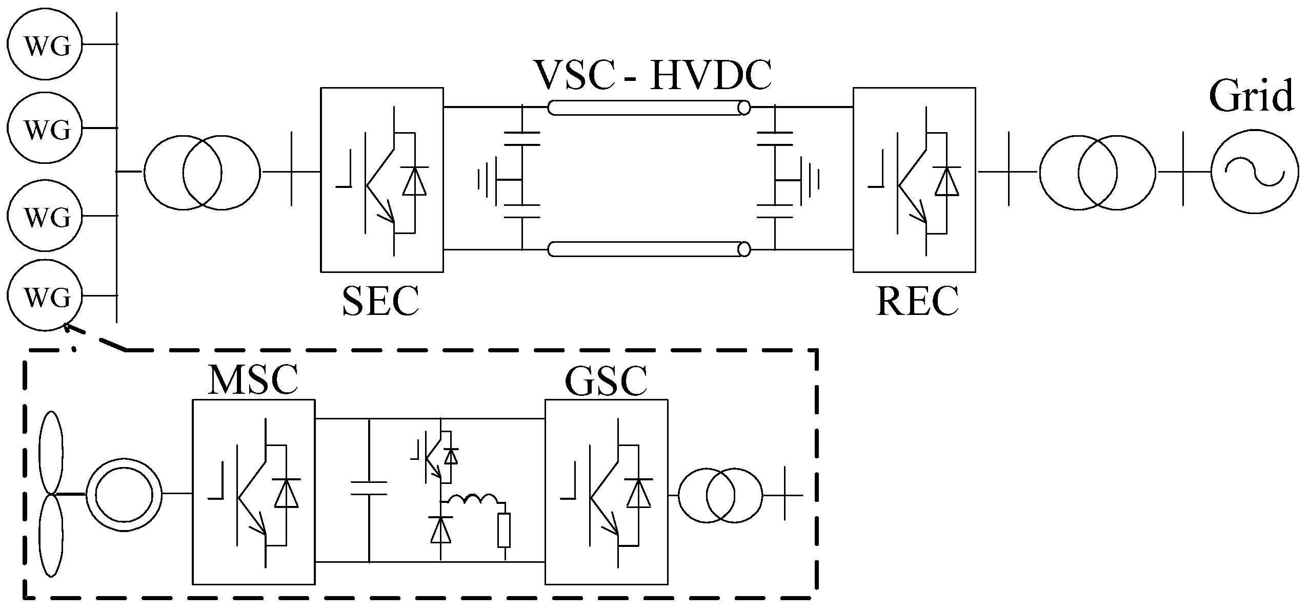
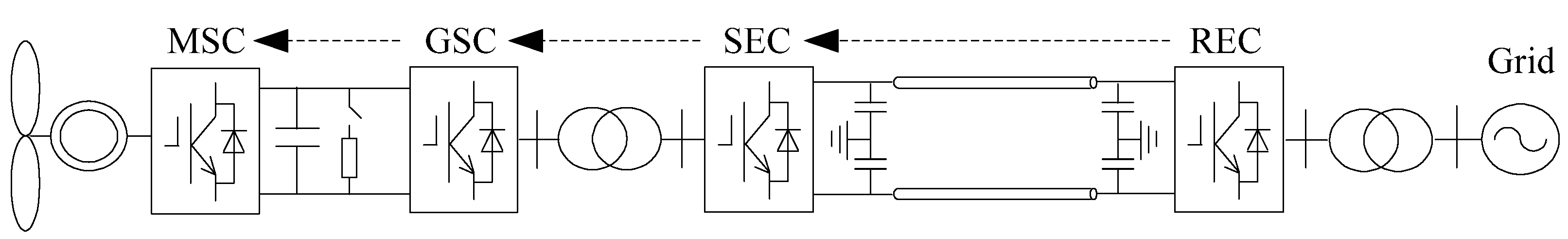
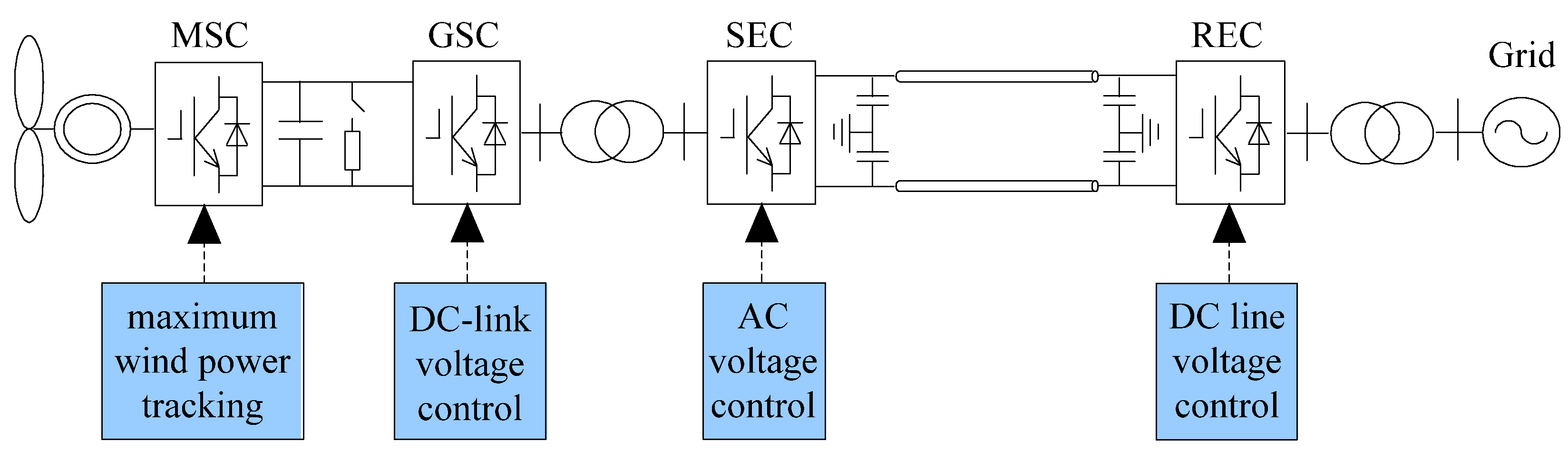
The typical configuration of a VSC-HVDC-based wind power system is shown in
Figure 1. VSC-HVDC system adopts the common end-to-end structure and the wind farm chooses PMSG WTs which are connected to the grid through a fully rated back-to-back converter. The parameters of the PMSG and wind farm network are listed in Appendix
Table A1. The parameters of the VSC-HVDC and DC line are listed in Appendix
Table A2.
Figure 1.
VSC-HVDC-based PMSG wind power system.
Figure 1.
VSC-HVDC-based PMSG wind power system.
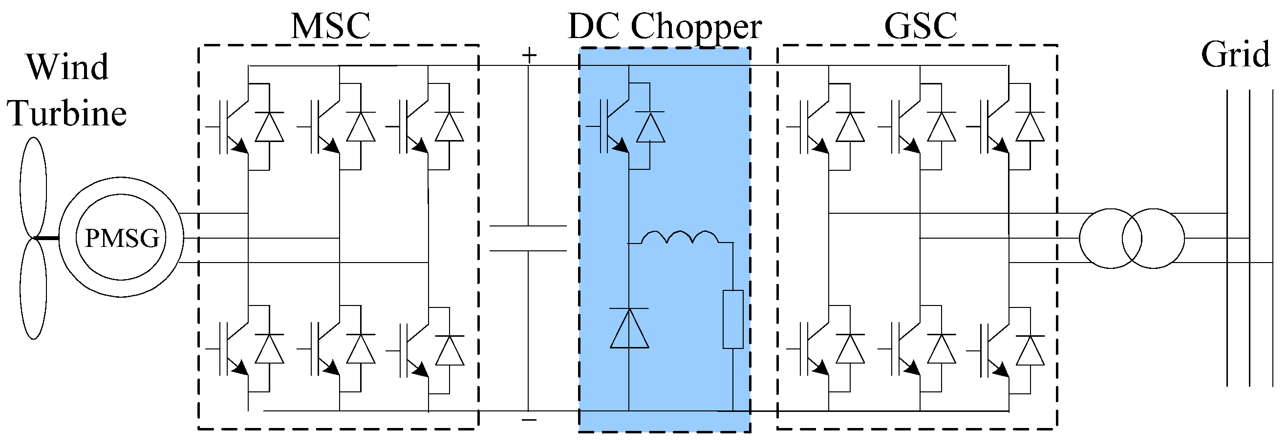
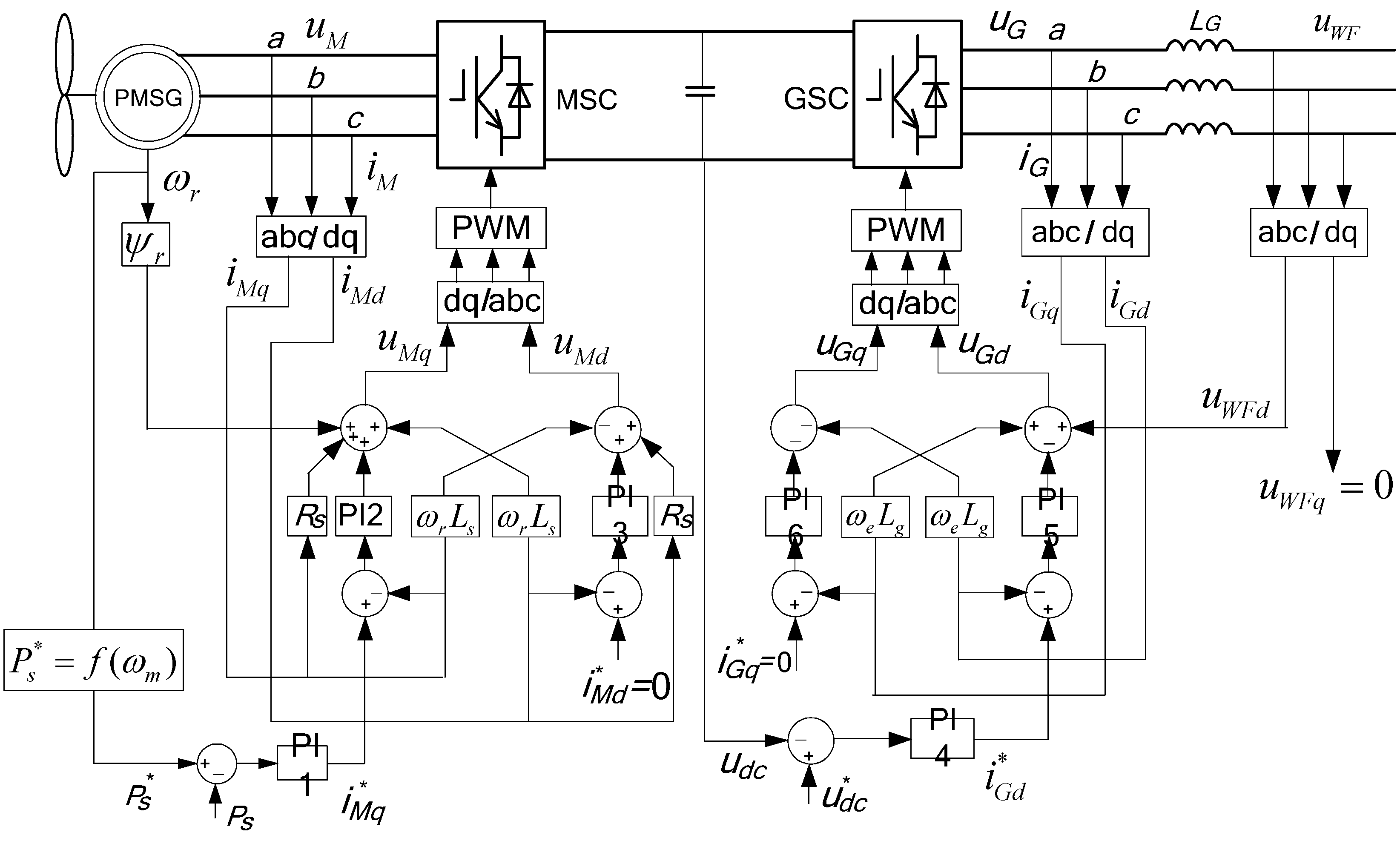
The structure of a PMSG WT is shown in
Figure 2. Typically, the motor side converter (MSC) works as a rectifier and controls the active and reactive power output of the PMSG. Meanwhile, the grid side converter (GSC) works as an inverter, maintains the DC-link voltage, and controls the reactive power exchange between the generator and the grid [
12,
13,
14,
15]. The DC chopper circuit, which consists of power electronic devices and unloading resistors connected in series, is used to maintain a stable DC-link voltage during grid faults. VSC-HVDC is composed of a sending end converter (SEC) station on the wind farm side, a receiving end converter (REC) station on the other side of the power grid, and a DC line between SEC and REC; both sides have DC capacitors to provide stable DC line voltage. SEC station and REC station have the same structure both being composed of three-phase voltage source converters.
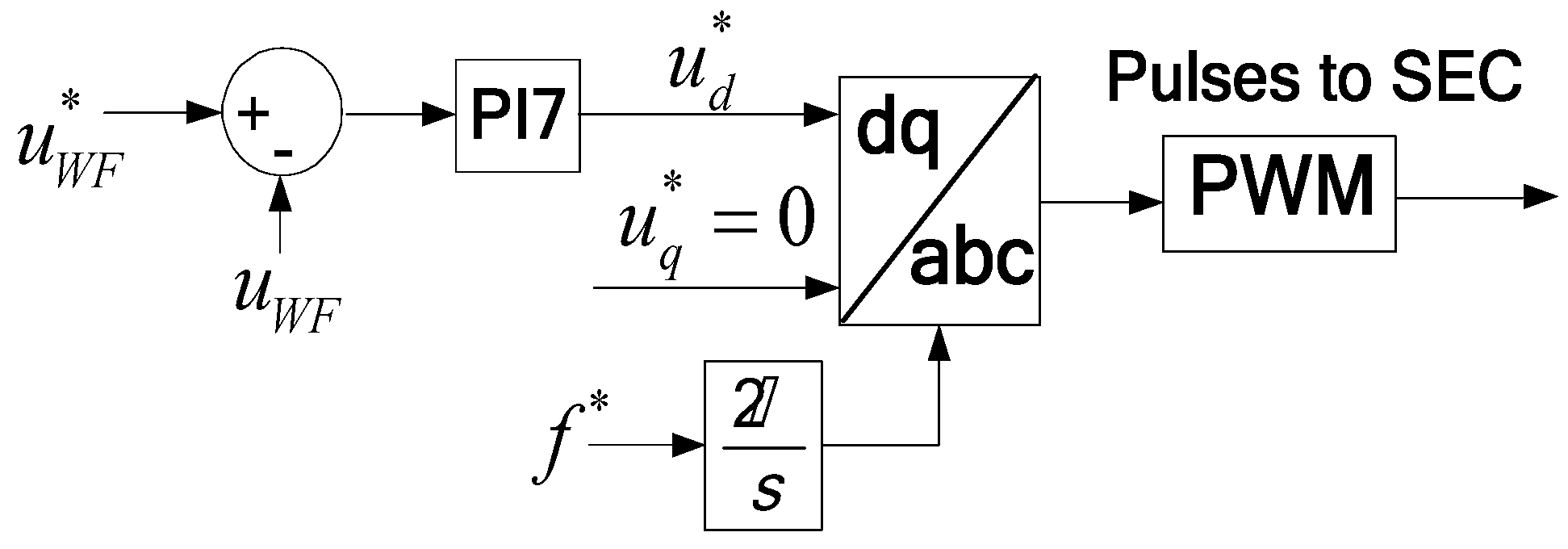
A VSC-HVDC-based wind power system is more flexible in control mode. The reactive power at two converter stations can be controlled independently, so reactive power compensation devices are not needed here. The SEC station can control the voltage and frequency of the wind farm at the same time, while the PMSG WT do not need to change the control strategy and can maintain the maximum wind power tracking control.
Figure 2.
The structure of PMSG WT system.
Figure 2.
The structure of PMSG WT system.
4. LVRT Control Strategy for the VSC-HVDC-Based Wind Power System
4.1. Transient Characteristics of the VSC-HVDC-Based Wind Power System
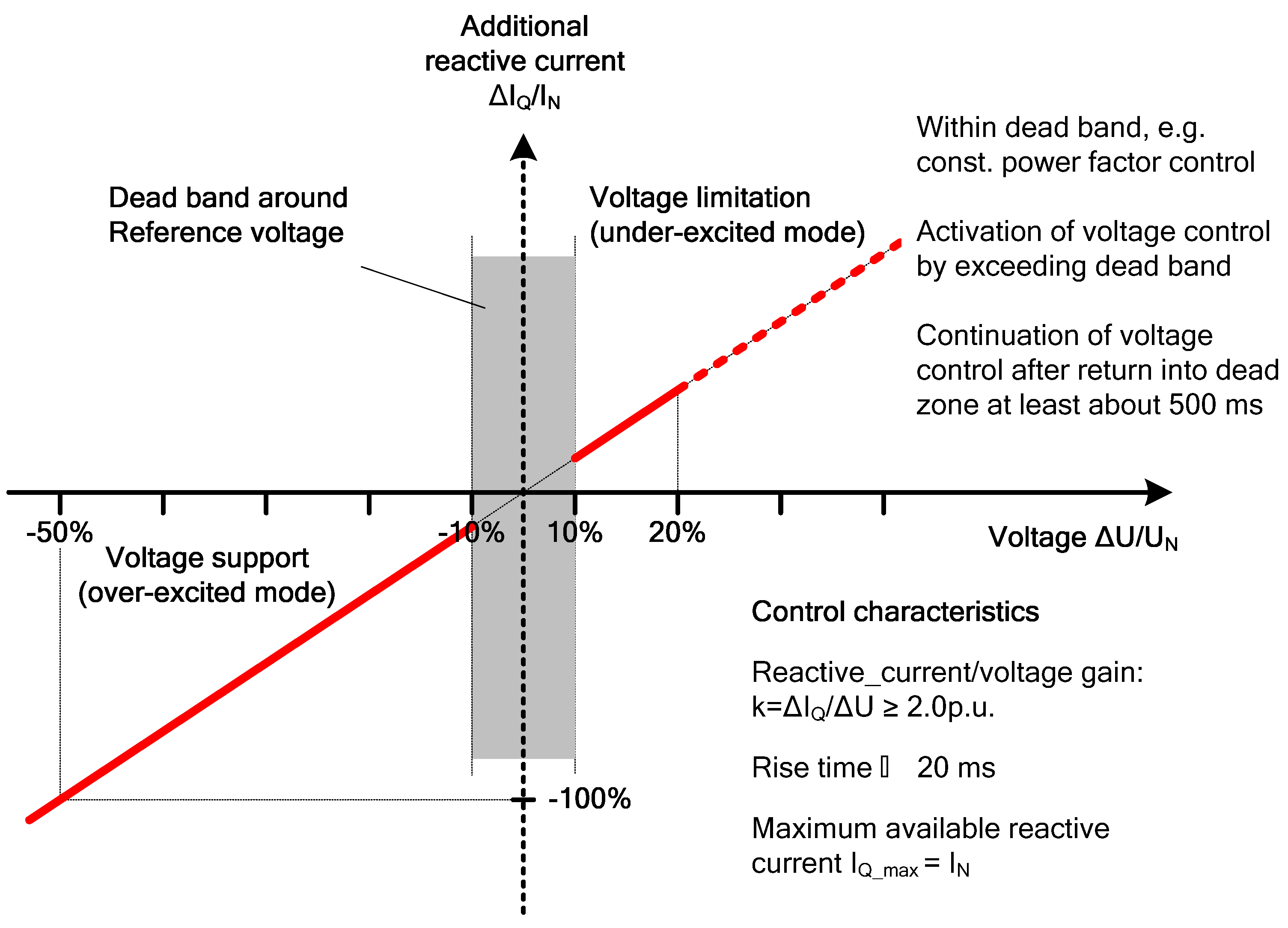
During grid faults, wind farms should provide reactive power to the grid to support the voltage recovery, while the reactive power support of the VSC-HVDC-based wind power system is executed by the REC station. According to the German grid code from E.ON [
2], as shown in
Figure 7, for every drop of 1% in the rated grid voltage, the reactive current that the wind farm needs to provide to the grid is 2% of the rated current [
3].
Figure 7.
Reactive current support requirement [
2].
Figure 7.
Reactive current support requirement [
2].
Therefore, the reactive current references of the REC are:
where
uAC denotes the grid voltage;
uAC* denotes the grid voltage before the fault;
iRq is the
q-axis reactive current requirements of the REC. All values are given per unit (p.u.) and remain the same in the following sections.
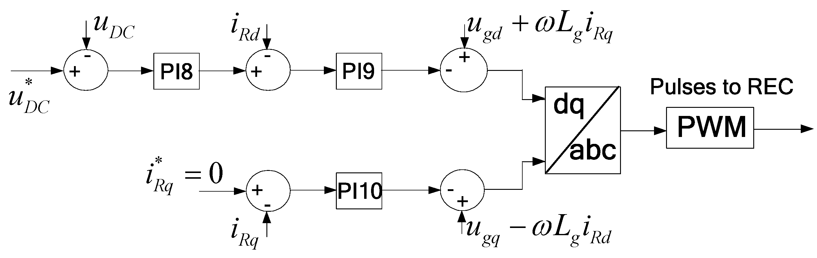
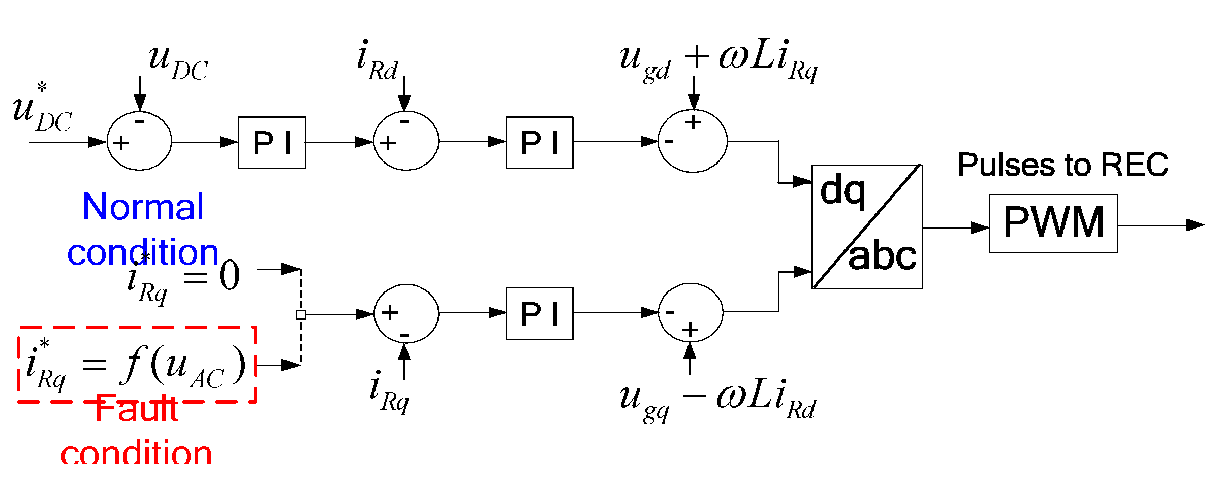
Once the power grid voltage drop is detected, the REC switches to reactive current priority and provides reactive current to support the grid voltage recovery according to Equation (5). The control diagram is indicated by red dashed box in
Figure 8. At this time, active current is limited in:
where
iRd and
iR,,lim are the
d-axis active current and rated current magnitude limit of REC, respectively.
Figure 8.
Control diagram of REC under fault condition.
Figure 8.
Control diagram of REC under fault condition.
The maximum power that can be transmitted to the grid is:
Thus it can be seen that the current limit of the converter and reactive current priority will lead to active current reduction; besides, due to the grid voltage dips, only a small part of the generated power can be sent by REC to the grid. Although there is a communication link between the two REC and SEC stations, if the wind farm is operating close to rated power when the fault occurs, without a coordinated control of VSC-HVDC and the PMSG WTs, it would lead to a significant power imbalance between these two stations. As a result, the DC line voltage would increase rapidly above the acceptable limits, which is unacceptable. This is the main problem that needs to be solved in VSC-HVDC connected wind farms. Then the LVRT coordinated control is put forward.
4.2. PMSG WT Power Control
In order to solve the problems mentioned above, communication is required between the VSC-HVDC stations and the PMSG WTs. Through the communication link, the fault signals can be sent to PMSG converters, and then the power output of the PMSG WT can be adjusted to smooth the power imbalance in the VSC-HVDC system.
As shown in
Figure 9, when a voltage drop is detected at the REC station, the fault signal is sent to MSC and GSC, communication link, r t of the PMSG WT can be reduced directly through MSC by regulating the power control mode, according to the following relationship:
where
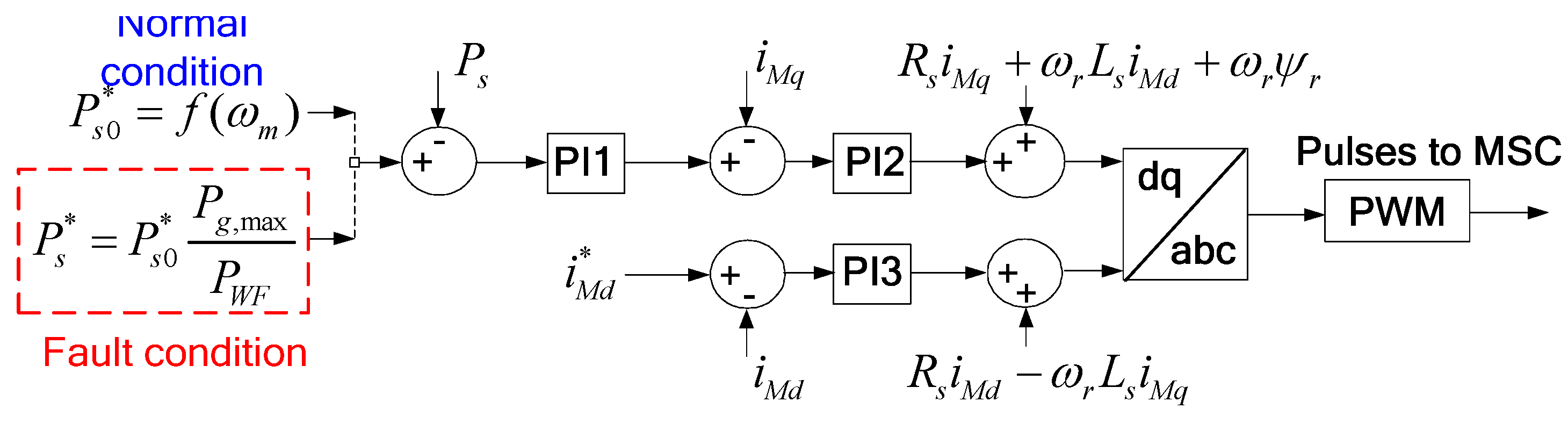
Ps0* and
Ps* denote the active power reference value of PMSG WT before and after the fault, respectively;
PWF and
Pg,max represent the power output of wind farm and the maximum power that can be transmitted to the grid, respectively.
Figure 9.
Communication link between VSC-HVDC and PMSG WT.
Figure 9.
Communication link between VSC-HVDC and PMSG WT.
At this time, the active power controller of the MSC no longer controls the generator power output along the maximum wind power tracking curve, but adjusts the generator speed dynamically in real time according to the power output
Pg,max. The control diagram is shown by a red dashed box in
Figure 10.
Figure 10.
Control diagram of MSC under fault condition.
Figure 10.
Control diagram of MSC under fault condition.
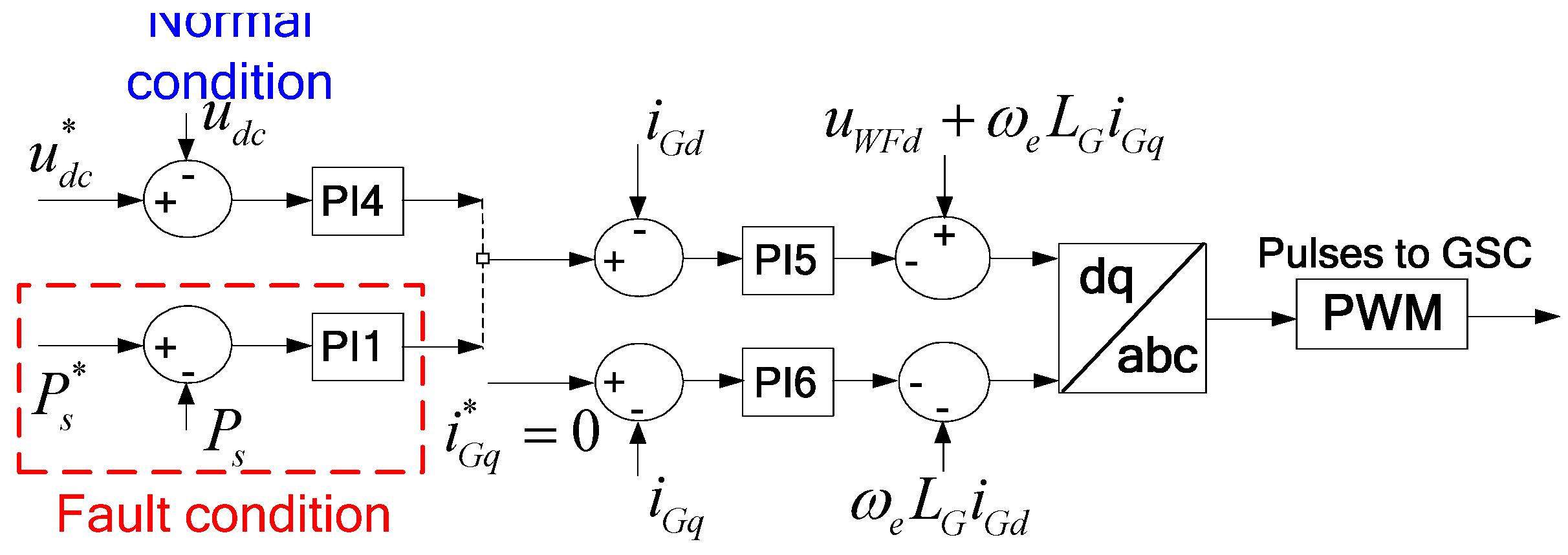
The power output of PMSG WT is reduced effectively, but due to the communication delay and the response speed of power control, the VSC-HVDC DC line voltage is still likely to rise in a short period of time. Therefore the active current control of the GSC converter also needs to be changed; the control diagram is indicated by a red dashed box in
Figure 11. In this way, the wind farm power export can be reduced in a few milliseconds. During this period, the voltage support function of GSC should be disabled to avoid conflict with the SEC control [
9,
10].
Figure 11.
Control diagram of GSC under fault condition.
Figure 11.
Control diagram of GSC under fault condition.
The above improvement of the PMSG WT control strategy can maintain the wind farm voltage unchanged; however, this method also has some disadvantages. Firstly, due to the reduction of generator power output, the PMSG rotor will speed up to deviate from the maximum wind power tracking curve and store part of the wind energy in the wind blades as rotational kinetic energy. PMSG is a multi-pole low-speed generator. Although its speed range is large, it can operate at 1.4 p.u. of rated speed only for a short time. When the voltage drop is relatively serious, the generator rotor sped to the upper limit still cannot meet the requirements. Secondly, the generator power control needs a certain response time and the power reduction is also restricted by the generator rotor speed limit, which will lead PMSG WT DC-link overvoltage [
19].
4.3. PMSG WT Hierarchical Control Strategy
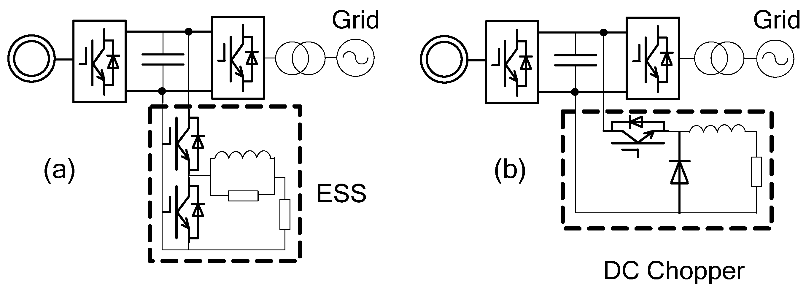
Known from the above analysis, when grid voltage dips become serious, the PMSG power control alone will not be able to maintain a steady DC-link voltage. The control strategy of PMSG WT during the LVRT period should be further improved to ensure the DC-link voltage stability. Some DC-link protection circuits which are easy to implement in engineering maybe used, such as Energy Storage System (ESS), DC chopper, pitch angle control,
etc., [
20,
21,
22,
23,
24,
25,
26], as shown in
Figure 12.
Figure 12.
DC-link protection circuits. (a) ESS; (b) DC Chopper.
Figure 12.
DC-link protection circuits. (a) ESS; (b) DC Chopper.
As shown in
Figure 12a, the ESS uses a super capacitor as an energy storage battery, so it can not only absorb the energy when the DC-link is in overvoltage, but also can release energy when the DC-link voltage is too low, thereby maintaining the DC-link voltage within a certain range. Its main disadvantage is that the cost is too high, the control is complex, and the reliability of the system is reduced, and its application is limited. The DC chopper is constituted by a Buck circuit and an unloading resistance, whereby the excess energy is consumed through the resistance. The DC chopper as shown in
Figure 12b is not only simple to control, but also responds fast, although a long time running can lead to the temperature of the DC unloading resistance being more than the security settings. Pitch angle control can fundamentally reduce the wind energy absorption, but the response is slow with a maximum change of 10°~20° per second [
27]. Therefore it only can be used as an auxiliary method, and used in conjunction with other methods. These two methods are affected by the degree of grid voltage drop and the PMSG WT DC-link overvoltage, but can complement each other in different fault conditions, forming a hierarchical control together with the generator power control. The generator power control constitutes layer 1 control, while the pitch angle control and DC chopper constitute layer 2 control.
The specific work principle of hierarchical control strategy is as follows: when the REC current rises to its upper limit, layer 1 control starts to reduce generator power output through the MSC power control and GSC current control, making the PMSG rotor speed up to deviate from the maximum wind power tracking curve. Once the voltage drops seriously and the generator speed reaches the upper limit, layer 2 control is activated. The emergency pitch angle control makes the WT pitch angle increase immediately, so that the captured mechanical torque decreases. However, the pitch angle changes slowly, to a maximum change of 10°~20° per second, so the speed is set to 15° per second in this paper. It should cooperate with the DC chopper in order to avoid transient high voltage at the DC-link due to the pitch angle change response. The DC chopper is triggered when the DC-link voltage exceeds 1.1 p.u. and quits when the DC-link voltage is below 1.1 p.u.
For the VSC-HVDC connected wind farm, PMSG converters only need to be installed with part power DC choppers, and the heat pressure of the DC unloading resistance is reduced because the reactive power support is executed by the REC station and the full GSC capacity can be used for active output.
4.4. Coordinated Control Strategy
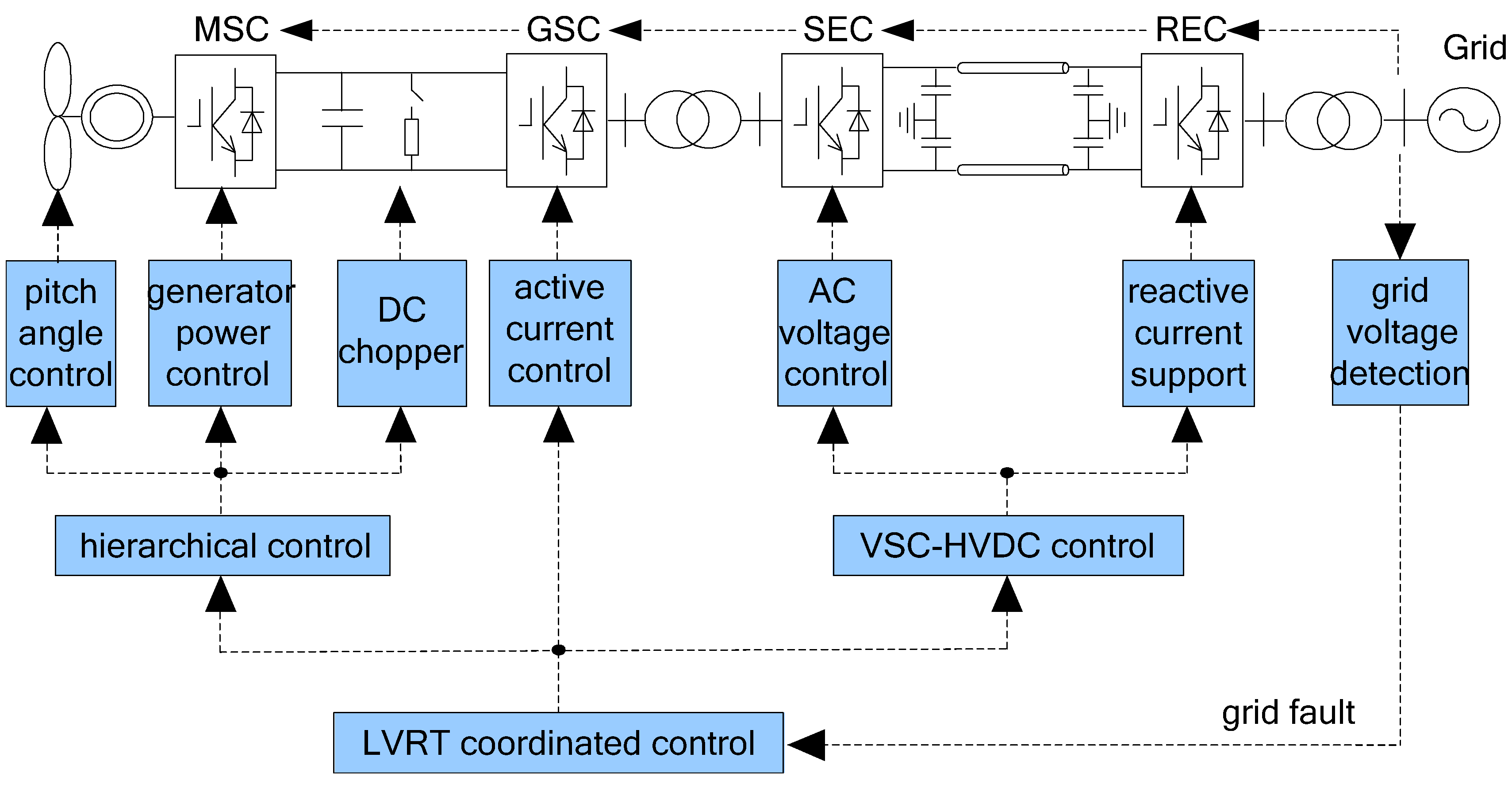
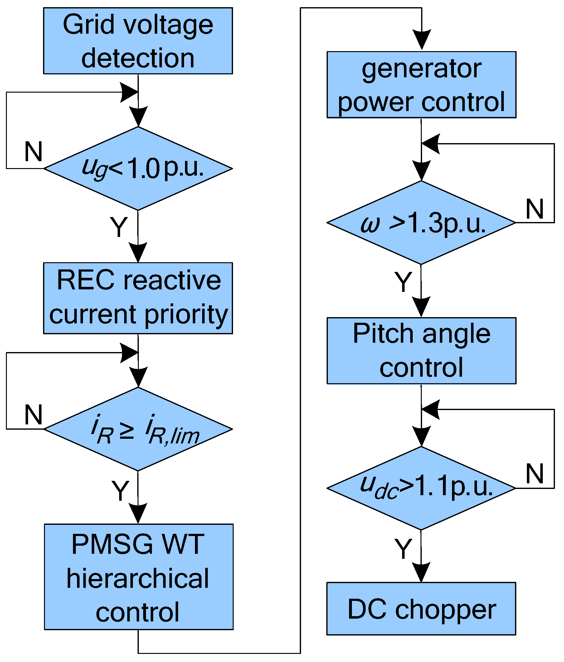
Combining the VSC-HVDC LVRT control strategy with the PMSG WT hierarchical control strategy, the LVRT coordinated control strategy based on PMSG WT power control can be drawn out. The control flow is shown in
Figure 13.
Figure 13.
The LVRT coordinated control diagram of VSC-HVDC-based wind power system.
Figure 13.
The LVRT coordinated control diagram of VSC-HVDC-based wind power system.
When a grid voltage drop is detected, the REC station switches to reactive current priority and provides reactive current to the power grid to support the grid voltage recovery. When the current of the REC station has reached its upper limit, the WT active power control will be launched. The GSC and MSC reset the active power and current reference value according to the fault signal sent from the REC station so as to control a fast reduction of the exported power, and then maintain the power balance on the DC line of the VSC-HVDC. PMSG WT hierarchical control will be triggered according to the different fault degrees. This new LVRT method is based on the coordinated control of the VSC-HVDC system and PMSG WTs, not only being able to provide reactive power support, but also it can quickly reduce wind farm power output, maintain DC line voltage stability, and realize the LVRT function of VSC-HVDC-based wind power system. The control flow is shown in
Figure 14.
In this paper, the current upper limit of the converter is set to 1.2 p.u. and the PMSG rotor speed upper limit is set to 1.4 p.u. It can be calculated from Equations (5)–(7) that when the power grid voltage is lower than 0.86 p.u., the REC current will reach the upper limit and the coordinated control algorithm should be activated. Due to the generator speed inertia, the PMSG rotor speed upper limit in layer 2 control is set to 1.3 p.u. in the following simulation. When the rotor speed reaches 1.3 p.u., its power output reduces to 0.8 p.u. Simultaneously, as the GSC only sends out active current and the wind farm export voltage is not changed in hierarchical control, the control strategies for the corresponding levels can be determined, as shown in
Table 1.
Figure 14.
The LVRT coordinated control flow.
Figure 14.
The LVRT coordinated control flow.
Table 1.
PMSG WT hierarchical control scheme.
Table 1.
PMSG WT hierarchical control scheme.
| Voltage dip level | Grid Voltage Range (p.u.) | LVRT Control Strategy and Hierarchical Control Strategy |
|---|
| First level | 0.86 ≤ Ug | REC converter current do not reach the upper limit |
| Second level | 0.74 < Ug < 0.86 | add PMSG WT power control |
| Third level | Ug ≤ 0.74 | add pitch angle control and DC chopper |
5. Simulation and Analysis
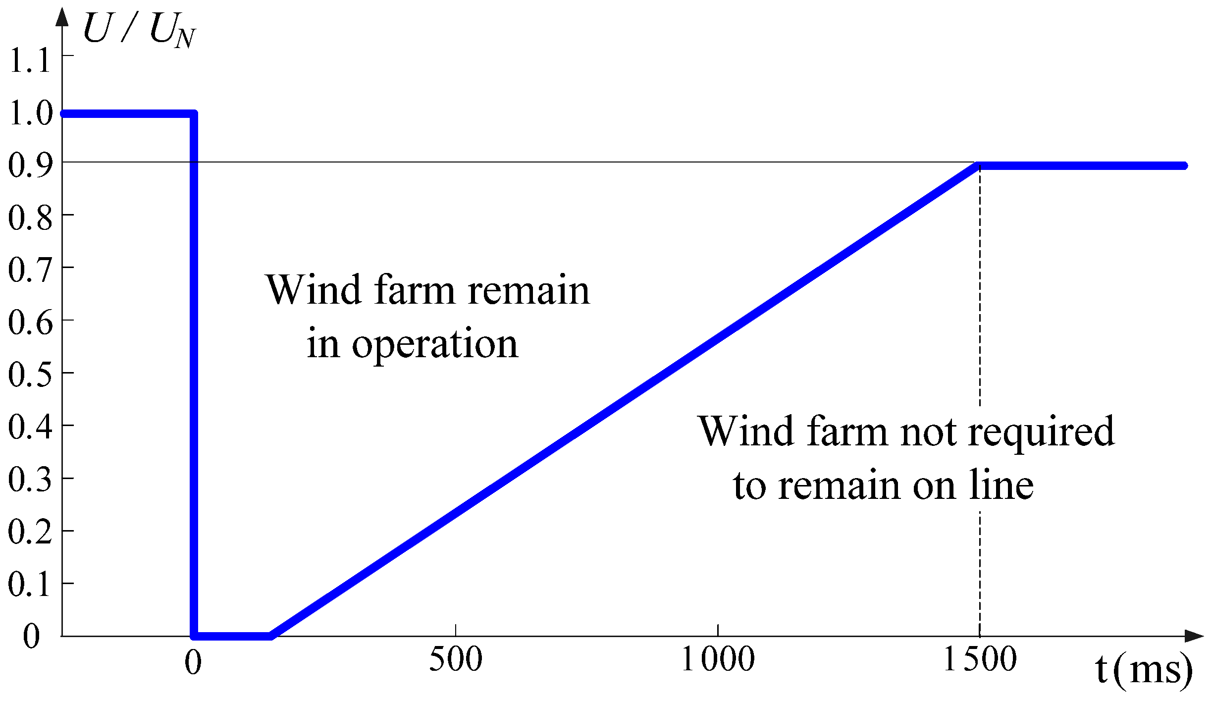
Wind farms must remain in operation not only during unbalanced faults but also during three-phase short circuits near the connection point to the grid. According to the E.ON grid code, wind farms must withstand voltage sags down to 0% of the nominal voltage at the point of common coupling for durations of not less than 150 ms. However, depending on the network and wind farm configuration, this does not always lead to zero voltage at the wind generator terminal side. A relatively simple calculation indicates that the corresponding voltage dip at lower voltage levels, near the wind generator terminal side, is most likely to be somewhat above 15% [
28]. Therefore, the LVRT requirement in this paper is shown in
Figure 15. Wind farms are required to withstand voltage sags down to 15% of the nominal voltage for durations not less than 300 ms.
To evaluate the proposed LVRT coordinated control for a VSC-HVDC-based wind power system, simulations are carried out using Matlab/Simulink SimPowerSystems Toolbox. In this simulation model, a 10 MW wind farm composed of five 2 MW PMSG WTs is connected to a VSC-HVDC system through a 690 V/10 kV transformer. The converter stations of the VSC-HVDC are 10 MW and the DC transmission line is 100 km long, with a DC line voltage of 20 kV and a DC capacitor of 250 mF. The REC is connected to a 110 kV power grid through a 10/110 kV transformer. Communication delay between the REC and SEC is 10 ms. The wind farm is represented by an equivalent aggregated model as one PMSG WT with a DC-link voltage of 1600 V and DC capacitor of 20 mF. The 10 MVA converters are modeled as ideal IGBT switches and controlled by PWM at 2 kHz switching frequencies. Considered the most severe case, the WT is operating with a rated wind speed at unit power factor and output the maximum power before the fault.
Figure 15.
LVRT requirement of E.ON grid code during grid fault.
Figure 15.
LVRT requirement of E.ON grid code during grid fault.
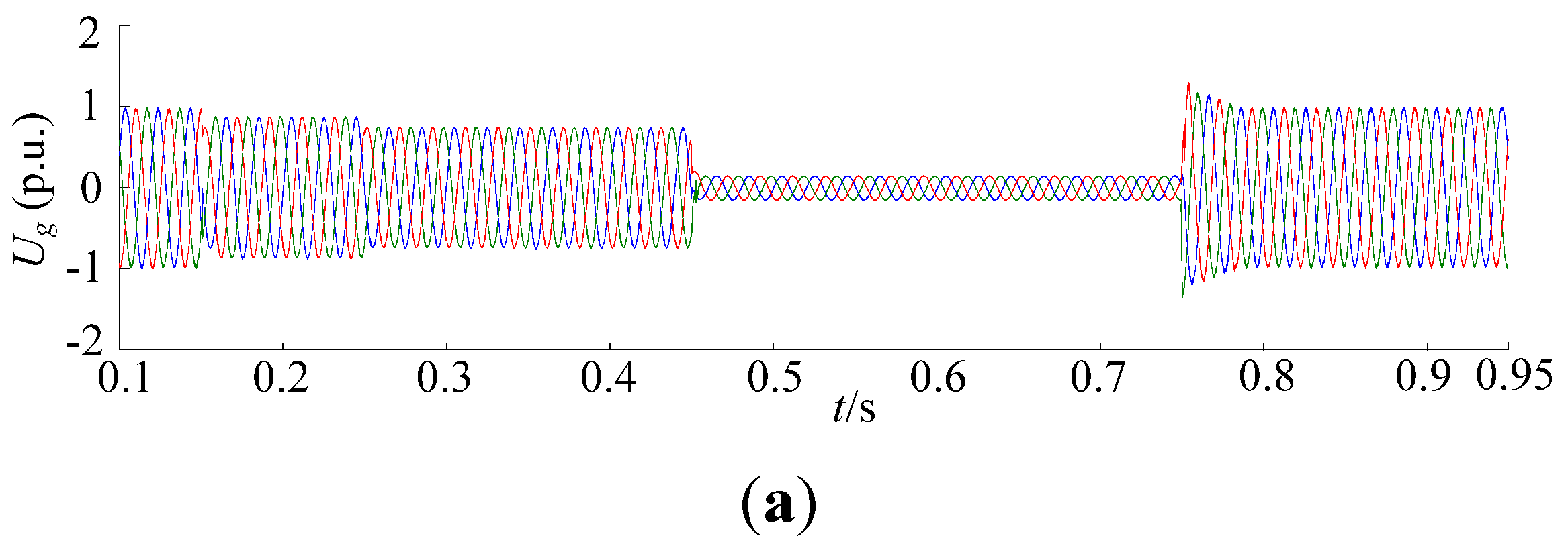
As shown in
Figure 16a, the PMSG WT is operating with rated wind speed at unit power factor before 0.15 s and the active power output of wind farm is 1 p.u. Due to a grid fault, at
t = 0.15 s, the grid voltage at the REC terminal dropped to 0.86 p.u. for a duration of 100 ms; at
t = 0.25 s, the grid voltage further dropped to 0.75 p.u. for a duration of 200 ms; and at
t = 0.45 s, the grid voltage dropped to 0.15 p.u. for a duration of 300 ms. After 0.75 s, the power grid is restored and the wind power system returns back to rated operation state.
At
t = 0.15 s, the grid voltage at REC terminal dropped to 0.86 p.u., REC provided reactive power according to the requirement of approximately 0.241 p.u., and the converter current did not reach the upper limit, active power output remained at 1 p.u.; at
t = 0.25 s, the grid voltage further dropped to 0.75 p.u., REC provided reactive power of 0.375 p.u., and the converter current reached the upper limit, active power output was limited at 0.818 p.u.; at
t = 0.45 s, the grid voltage dropped to 0.15 p.u., REC provided reactive power of 0.18 p.u., and the active power output was limited almost to zero. These currents, reactive powers, and active power outputs of the REC are shown in
Figure 16b,c, respectively.
Figure 16.
The simulation results of the LVRT coordination control for the VSC-HVDC-based wind power system. (a) Grid voltage; (b) REC current; (c) REC active power and reactive power; (d) Wind farm export voltage; (e) Wind farm export current; (f) GSC active power output; (g) DC line voltage of VSC-HVDC.
Figure 16d–g shows the voltage, current, and active power output at the wind farm export and DC line voltage of the VSC-HVDC, respectively. When the grid voltage dropped to 0.86 p.u. at
t = 0.15 s, the REC current did not reach the upper limit, and the active power output and DC line voltage of the VSC-HVSC both remained at 1 p.u.; then the grid voltage dropped to 0.75 p.u. at
t = 0.25 s, the wind farm export current was dropped to 0.818 p.u. After 10 ms delay according to Equation (7), so that the active power output was limited at 0.818 p.u; at
t = 0.45 s, the grid voltage fell off to 0.15 p.u., wind farm export current continued to drop more. The wind farm export current and active power output almost dropped to zero. Due to the communication delay between the REC station and SEC station, there was a short rise on the DC line voltage of the VSC-HVDC system, but it was always less than 1.05 p.u., and in compliance with the LVRT requirements.
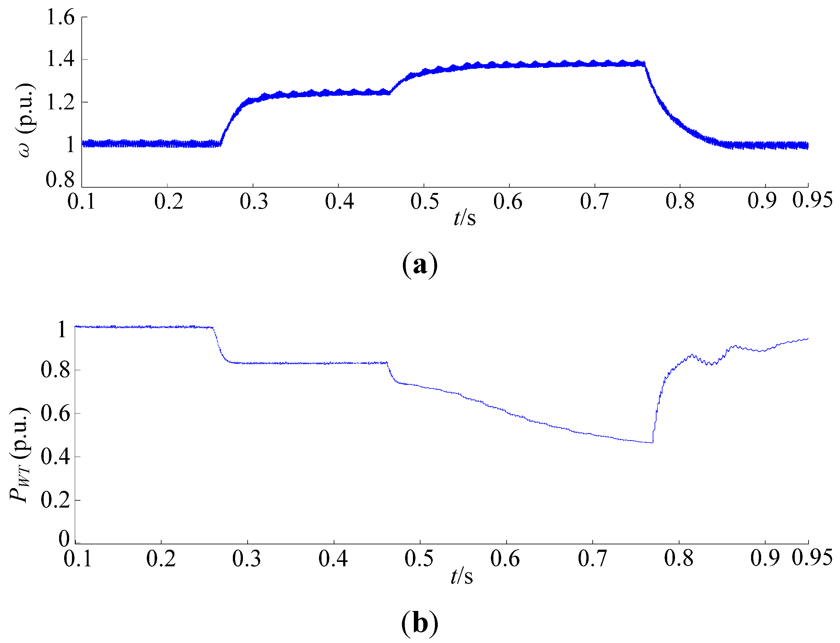
Figure 17 shows the PMSG hierarchical control simulation results. At
t =0.15 s, the grid voltage dropped to 0.86 p.u., hierarchical control was not started; when
t = 0.25 s, the grid voltage dropped to 0.75 p.u., REC current had reached the threshold, belonging to the range of hierarchical control layer 1. The GSC controlled the wind farm power output drop, and the generator rotor was accelerated to reduce the WT generation power, as shown in
Figure 17a,b. Due to the speed control delay of MSC, there were a short PMSGDC-link voltage rise, but it was less than 1.05 p.u. and completely met the LVRT requirements, as shown in
Figure 17c; then at
t = 0.45 s, the grid voltage fell to 0.15 p.u., and generator speed had risen to the upper limit 1.3 p.u., but it still could not maintain the PMSG system energy balance. At that time, the hierarchical control layer 2 was activated. The pitch angle control began to change the WT pitch to reduce the power capture at the speed of 15° per second, from 0° to 4.5°, as shown in
Figure 17d. However, the pitch angle control had a certain inertia, and the PMSG DC-link voltage rose quickly during this period, exceeding 1.1 p.u., so the DC chopper was triggered to consume the extra energy, as shown in
Figure 17e. The unloading resistance is 2 Ω, and approximately 6.4 MW energy was consumed during this period.
Figure 17.
The simulation results for the PMSG WT hierarchical control during power grid faults. (a) Generator rotor speed; (b) Active power output of the MSC; (c) PMSG DC-link voltage; (d) WT pitch angle; (e) DC chopper current.
Figure 17.
The simulation results for the PMSG WT hierarchical control during power grid faults. (a) Generator rotor speed; (b) Active power output of the MSC; (c) PMSG DC-link voltage; (d) WT pitch angle; (e) DC chopper current.
When the power grid fault is restored at
t = 0.75 s, the system switches to stable operation control mode. Active power is recovered quickly, in compliance with the LVRT requirements for active power recovery time. From the simulation results of different depth drops of the power grid voltage, the following can be seen:
- (1)
By reducing wind farm power output LVRT coordinated control strategies can effectively control the VSC-HVDC power imbalance and maintain the DC line voltage. This method needs a communication link between the VSC-HVDC converter stations and PMSG WTs, and the communication delay has to be taken into account.
- (2)
MSC power control can reduce generator power output by making PMSG rotor speed up, but this has a certain delay. The PMSG is multi-pole low-speed generator. Although its speed range is large, it can only operate at 1.4 p.u. of rated speed for a short time.
- (3)
Pitch angle control can effectively reduce wind energy capture, but the response is relatively slow. The DC chopper responds rapidly and is simple to implement. The combination of these two methods can not only avoid the PMSG DC-link overvoltage, but also reduce the heat capacity limit of the unloading resistance.
6. Conclusions
In this paper, a new LVRT coordinated control strategy during grid faults has been developed for VSC-HVDC-based PMSG wind power systems, in which VSC-HVDC is controlled in concert with the wind farm. This LVRT coordinated control strategy combined with the PMSG hierarchical control strategy can reliably realize the low voltage ride-through of VSC-HVDC connected wind farms.
Under normal conditions, large scale wind farms connected into the power grid through a VSC-HVDC system, can not only solve the remote transmission problem, but also can provide reactive power support to the power grid in accordance with the grid code. During grid faults, the LVRT coordinated control and the corresponding wind turbine hierarchical control implement a fast reduction of the wind farm power output according to the grid voltage sag depth, maintaining the system energy balance as well as DC-link voltage stability. Simultaneously it reduces the heat capacity limit of the DC chopper.
The LVRT coordinated control strategy is easy to operate, as it just needs some modifications of the control algorithm of VSC-HVDC stations and PMSG WT converters. It not only realizes LVRT of the VSC-HVDC connected wind farms, but also improves the voltage stability and power quality of the wind power system. Therefore, it has a higher efficiency and utilization. Moreover, it has good portability and can be applied to all kinds of VSC-HVDC topologies.
As we understand, the differences in fault type, symmetrical or unsymmetrical, fault duration, the distance between PCC points and the fault location can cause different effects on VSC-HVDC-based wind power systems. The next study will focus on other symmetric grid fault conditions with longer fault duration and unsymmetrical grid faults.


