1. Introduction
A greener and more sustainable society needs renewable energy under all its forms, higher efficiency systems and a change of habits. Oil, chemicals and related industries, are nowadays evolving considerably due to market demands, unprecedented globalisation and the arising limitations from environmental concerns and security. Moreover, sustainable considerations combined with tools such as stakeholder analysis, key performance indicators (KPIs) and life cycle assessment (LCA) approach may cover the supply chain from cradle-to-the grave, being powerful approaches in a pre-design step [
1].
The energy sector is moving towards a new energy paradigm, which favours more efficient conversion processes (due to more scarce and expensive fossil fuels), renewable sources and micro-generation (
i.e., smart grids), through tailor-made approaches, adapted to the needs and resources of each area. Decentralisation ideally involves more population participation and supply security. There will not be a unique technology or renewable source massive implementation, but a combination of various conversion technologies to meet the energy demand [
2]. The alternatives to centralised and conventional sources of energy should be sustainable in the time, which implies a responsible resource exploitation, by balancing source availability with electricity demand, and therefore with the capacity of the plant.
Biomass can play an important role in both centralised (large scale) and decentralised or distributed (small scale) energy systems. Each scale evolves into different challenges in the use of biomass. As immediate solutions, where technology is already well developed, biomass at large scale can be co-used properly with fossil fuels. Biomass systems at small scale are appropriate for residential uses and rural electrification in emerging countries [
3].
Bioenergy or energy from biomass is a promising contributor in the upcoming energy mix. In order to become a key actor, technological, economic, environmental and social aspects need to be advantageous if compared to conventional fuels. As one of the main points to improve, biomass needs to be densified to increase its calorific value, while easing its transportation and stabilising moisture and dry matter contents. That is the reason why biomass pre-treatment becomes crucial for the development of sustainable supply chains.
The use of coal can be reduced if appropriately mixed with biomass. Around the world, requirements for energy and electricity are largely met by fossil fuels, and coal is widely selected as it is a secure, low-cost and high energy density source; coal resources are abundant and broadly distributed geographically [
4]. Coal is also relatively easy to mine, ship, and store. It is expected to contribute significantly in the future energy needs in many nations, especially in fast-developing countries such as China and India [
5]. These qualities make coal-fuelled power plants important electricity price stabilisers and reliable power producers, especially in electricity systems with price-volatility or intermittently available resources.
In this context, it is worth noticing that coal demand had an average growth rate of 3.3% per year, between 2010 and 2013, and is expected to reach nine billion tonnes per year by 2019. According to the International Energy Agency (IEA) Executive Director, Maria van der Hoeven, although the contribution that coal makes to energy security and access to energy is undeniable, coal use in its current form is unsustainable, which makes the deployment of carbon capture and sequestration a priority [
6].
On the other hand, according to the Energy International Agency (EIA), the global energy demand is set to grow by 37% by 2040 [
7,
8]. As example, the European Union has established a target of 20% share of renewable energy out of the total European energy consumption by 2020 [
9]. The U.S. in its Energy Independence and Security Act (EISA) of 2007 states that advanced biofuels shall supply at least 21 billion gallons of U.S. motor fuels by 2022 [
10]. In this context, biomass exploitation becomes into a need.
1.1. Challenges in the Bioenergy Sector
The development of a successful bioenergy sector in developed and developing nations, through centralised and more decentralised systems, will make a useful long-term contribution to diversity, security and self-sufficiency of energy supply [
11]. Current challenges in the worldwide energy sector reflect three main issues: natural sources diminution, climate change and technology development. Within this context, bioenergy is one of the most appreciated options to mitigate Greenhouse Gases (GHG) emissions by replacing conventional sources in vehicles fuel and in electric power generation, certainly by adequately exploiting biomass resources and the multiple technology options [
12].
Bioenergy challenges are classified into two main blocks: energy generation and biomass as a source.
Figure 1 shows the major topics to be addressed by these blocks: (i) energy generation deals with the different biomass conversion routes, for fuels or electricity production, to be brought into market status; and (ii) biomass as a source, faces controversies like land use, while it is also concerned with globalisation and global markets.
Figure 1.
Bioenergy and concerned actuation areas.
Figure 1.
Bioenergy and concerned actuation areas.
In relation to the first block, global trends are promoting the utilisation of renewable sources as alternatives to fossil fuels to mitigate climate change and to alleviate the peak oil effects. In poorer areas, it is equally important to promote energy access through renewable sources at affordable prices [
13]. As [
14] and [
15] point out, the current energy models are biased towards industrialised countries because these are usually developed by experts and/or organisations that live and have been educated in industrialised countries. Accordingly, not only economic factors should be revised, but also types of demands, capability for operational and maintenance tasks or accessibility to the grid, to come up with more versatile models capable of looking into each project through its own reality, context and particularities.
Concerning the second block, biomass as energy source is coupled with two important economy sectors: agriculture and waste management. Agriculture can be used to produce food, feed, fuel and fibre (the so-called “4Fs”) creating a certain controversy and competitiveness for the land use, and therefore, for water use. As last instance, land as a resource is a protector of ecosystem systems, deals with the pressure of population growth, life styles variations and climate change consequences [
16]. Residues management is interlinked with other markets: they can be used as raw materials, as feed or as fertilizer, or in other industries that treat them to be further used in other processes. This leads into a complex competitive trade, where prices are set by the demand [
12]. Biomass markets are changing from exclusively national to international markets: globalisation makes accessible a broad range of globally dispersed potential suppliers and consumers. In order to develop a stable market with biomass as a commodity, supply and demand should be secured, in a sustainable way, while meeting the appropriate technical standards [
17]. As the works of Janssen
et al. [
18] and Madjera [
19] point out, developing countries such as those in Africa, have the potential to become significant producers and exporters of raw biomass while supplying their basic needs.
Overall, biomass can provide a larger energy share than the one that provides nowadays. For that to become a reality, technological, economic and social barriers have to be overcome [
20]. As a result, efforts are concentrated on developing integrated frameworks to support the decision-making process. This is further described in the current paper, which is principally focused on gasification and combustion technologies.
The Scale of the Problem
Biomass as energy source, in comparison with fossil fuels, has a lower calorific value as well as intrinsic characteristics that derive into technological limitations. That is the reason why 100% biomass to energy projects typically employ small scale conversion systems. Moreover, they tend to be placed close to the biomass generation source as well as close to the biomass demand points, to avoid high logistic and network infrastructure constraints [
21,
22,
23]. According to [
12], large gasification systems are from 10 MW
th, and small gasification systems cover the range from few MW
th to less than 100 kW
th. In terms of electricity and in accordance with [
24], small scale gasification plants enclose plants with a power up to 200 kW
e. These ranges lead to significant differences in terms of land use for the plant infrastructure, investment, operation and maintenances costs and evidently, plant dimensions (as example, the ELCOGAS integrated gasification combined cycle (IGCC) power plant uses a land extension of 480,000 m
2, while a small scale gasification plant can occupy around 25 m
2, as it is the case of the real scale pilot plant built in our laboratory at the Universitat Politècnica de Catalunya).
Centralised energy systems (CES) are defined here as large power plants that inject electricity to the grid and transport the raw material or energy source to the plant;
decentralised or
distributed energy systems (DES) entail localised electricity generation near the demand points and near the biomass production places. There exists no agreement in the literature about the definition of distributed generation; nevertheless it is usually perceived as small scale electricity generation [
25]. The literature overviews from [
26] and [
25], point out that the term refer to: (i) stand alone or autonomous applications; (ii) stand-by sources that supply power during grid outages; (iii) co-generation (or waste heat recovery) installations with power injection to the grid (if the DES has a higher power production than the local demand); (iv) DES that support the grid by decreasing power losses and improving the system voltage profile and (v) to energy systems connected directly to the grid that sell the electricity produced. This work uses the term DES as stand alone applications, with co-generation possibilities. See in
Figure 2 an overview of centralised
vs. distributed systems.
Figure 2.
Conventional centralised and decentralised based systems.
Figure 2.
Conventional centralised and decentralised based systems.
The supply chains of decentralised and centralised systems are studied in this paper, for two well differentiated concepts: rural/urban areas in developing/developed countries. This terminology does not have a well extended norm of usage; one possible definition for rural area uses a threshold of 150 inhabitants/km
2, including countryside, towns and small cities. Other definitions take into account towns and municipalities outside the urban centres, with population of 10,000 or more; or population living outside regions with major urban settlements of 50,000 or more people, dividing the areas into “metropolitan adjacent” or “not adjacent” categories [
27]. Urban areas include a central city and the surrounding dense areas that have together a population of 50,000 or more, encompassing a minimum of 2500 people, the minimum of which (1500 people) residing outside institutional group quarters, according to the United States Census Bureau, [
28]. The developed-developing countries division is more controversial, since it is difficult to assess the standards of living for worldwide countries. For instance, the World Bank (WB) classifies the countries according to their gross national income (GNI) for year 2013, being developing countries those ones with a GNI lower than US$4125 [
29]. The World Energy Assessment from the United Nations Development Program [
30] (UNDP), the United Nations Department of Economic and Social Affairs, and the World Energy Council, (2004) uses the term industrialised country to refer to high-income countries that belong to the Organisation for Economic Co-operation and Development (OECD). In this way, developed countries are also called industrialised. In this review, both terms, industrialised and developed are used.
Energy chains should be developed according to the context of each country/project and taking into account economic, environmental and social issues. Consequently, even if the technology to be implemented is the same in developed and developing countries (
i.e., gasification), the specific power to produce, and the energy chain itself (distance to raw materials, to existing grids,
etc.) should be characterised according to features such as the sector financing, the existence of a grid, the grid distribution losses, the demand,
etc. [
14,
31]. Gasification principles for large and small scale gasification are the same, but the type of reactor as well as the final syngas or producer gas composition and uses are generally different. This work describes further three plant layouts, which have been chosen because of the current challenges in process design and in supply chain management: large scale gasification of biomass-coal blends, represented by IGCC power plants, with carbon capture and storage (CCS) technology (IGCC-CCS), small scale biomass gasification which considers the produced gas usage in a gas engine (BG-GE), and co-combustion in large scale power plants,
i.e., in retrofitted pulverised coal (PC) power plants. The next two sections describe: (i) the main characteristics of biomass and the range of available technologies and (ii) the techniques used in a pre-design stage, to approach a biomass-to-energy problem.
1.2. Biomass as a Resource
Biomass is defined as “all the organic matter contained in plant and animal based products (including organic wastes) that can be captured and used as a source of stored chemical energy” [
11]. Biomass can be classified into three large categories according to its origin [
11,
12]: primary, secondary and tertiary biomass. See in
Figure 3 this well extended biomass classification, detailing sources and raw materials.
According to Sim [
11], biomass contributes significantly to the world’s primary energy supply, with 45 EJ/yr utilised in traditional and modern uses of biomass. Inside this number, the traditional use of biomass is estimated in 38 EJ/yr: it is the first energy source in developing countries (involving a 20%–35% of their national primary energy demand). The traditional use of biomass includes cooking and heating in a non-sustainable and inefficient way, through direct firing. As Silveira [
32] points out, “biomass is the fuel of the rural poor in developing countries”. There is no global information about the biomass market size; nevertheless it is assumed that the non-conventional use of the biomass is around 29 EJ/yr. The most relevant properties of biomass as energy carrier or chemical feedstock in thermochemical conversion processes (described in point 1.2.1) are, according to Rubiera
et al. [
33]: proximate and ultimate analyses, moisture content, lower and higher heating values (LHV and HHV), heats of formation, ashes content, biochemical composition (hemicellulose, cellulose, lignin and extractives), bulk density and grindability.
Figure 3.
Biomass sources classification, based on [
11,
12].
Figure 3.
Biomass sources classification, based on [
11,
12].
In Mathews [
34] is stated that the world is in a transition, from an economy fuelled by carbon from the past (“petro-economy”), to an economy fuelled by biomass, which is created through photosynthesis (“bio-economy”). According to Rosillo-Calle
et al. [
17] and Mathews [
34], bioenergy is extensively considered as carbon neutral, since the carbon emitted replaces the carbon absorbed during the crop growth. Nonetheless, each specific situation should be treated separately, and a LCA is recommended to calculate a complete carbon balance.
Three situations can be identified in general for fossil and biomass fuels, and are depicted in
Figure 4. Carbon positive fuels describe fossil fuels, as they release (net) CO
2 into the atmosphere. Carbon neutral fuels symbolise biomass resources, which absorb CO
2 from the atmosphere and release it again. Nevertheless, in practice, the carbon balance may be positive if fossil fuels are used at some echelon of the supply chain (mainly in biomass production and logistics). Carbon negative fuels represent biomass resources that absorb CO
2 from the atmosphere and release less CO
2 into it, because of directing part of the captured emissions during growing to the soil, as bio-char, or because of CSS use (called bionenergy with CCS, BECCS). Analogously, fossil fuels with CCS aim at a complete carbon neutrality, even if a small fraction of the CO
2 is not captured and hence it is discharged in the atmosphere. This neutral-carbon objective is theoretical, since a complete LCA should be performed to evaluate the trade-off between the emissions captured, and the emissions derived from the utilities consumed to perform this capture.
Figure 4.
Bio-sources carbon balance, based on Mathews [
34].
Figure 4.
Bio-sources carbon balance, based on Mathews [
34].
1.2.1. Available Technologies
An important portfolio of technologies allows for biomass transformation into heat, electricity, co-generation or transport fuels, and chemical feedstock. The most suitable conversion technology for a specific type of biomass depends on the composition, characteristics and amount of the resource, the desired final product, the environmental standards and the economic and project specific conditions [
12,
35].
Figure 5 shows the different available technologies and products obtained. Thermochemical conversion processes are suitable for low moisture content biomass (less than 50%), while physic-chemical and biological ones are adequate for humid biomass. A biorefinery integrates different technologies to produce heat, electricity, fuels and chemicals, at the same facility.
Figure 5.
Outline of the main biomass conversion processes.
Figure 5.
Outline of the main biomass conversion processes.
1.2.2. Biomass Trade
The sub-Saharan Africa (SSA) has the lowest electrification rate worldwide and still relies on the traditional use of wood for cooking and heating; 587 million people, 75% of the population, had no access to electricity in 2009, a number that is believed to rise up to 652 million by 2030 [
36,
37]. SSA agricultural waste potential for energy purposes is estimated at 136 PJ per year, while the forest residues in west and central Africa can reach 95 PJ per year [
36]. Identification of best strategies for modern wood technologies implementation and efficient small scale techniques are underway. As aforementioned this type of technologies are necessary to enable developing countries to become significant producers and exporters of raw biomass while supplying their basic needs. Along this lines, the European Union is a significant pellets consumer and importer: international imports have grown from 56 PJ in 2000 to 300 PJ in 2010 [
38]. According to EURELECTRIC, the solid-biomass provided by external suppliers may increase up to 1650 PJ by 2020. This is an example of how a global context can set the basis for a clear offer-demand opportunity: there is true momentum for solid-biomass market (with pellets as its main representative) in Europe, and SSA, together with other areas in America and Canada, has a potential that is nowadays underexploited.
In the medium and short term, the use of waste, which entails disposal problems, is a continuous source of organic matter for power production. Due to its distributed nature, biomass is appropriate for decentralised power generation in local areas, with certain centralisation for cost optimisation purposes [
39]. The pellets industry should not only use “high quality” woody resources as raw material, but also the wide range of available organic residues. Combinations of grass and woody materials, biomass with coal pellets, are under research as raw materials for pellets [
40].
Strategies for rural electrification and pellets market development must use criteria other than economic: sustainability, combining economic, environmental and social measures. The study of the whole bio-based supply chain at the design and planning stage is essential to propose long-term projects. Multi-objective optimisation tools to support decision-making (see next sections) in the field of renewable energy are being developed, used and improved. Solid-biomass (and specifically, pellets) is evolving towards an established renewable commodity internationally commercialised. Two main concerns must be solved in the context of SSA as a potential exporter: (i) resources evaluation and (ii) rural areas electrification.
1.3. Decision Making
Different tools and methodologies can be utilised to take decisions and diminish their associated risk. Multiple criteria decision analyses (MCDA) comprise the methods for process optimisation that contemplate multiple objectives. MCDA is applied to two types of systems: process and supply chain (SC) systems. In order to apply this decision analysis, the system is previously modelled or simulated. The following subsections explain the basis of this methodology.
1.3.1. Conceptual Design
The term “conceptual design” can be understood as the product design cycle phase where the basic solution is established through the formulation of abstract ideas with approximate concrete representations. Moreover, those ideas are evaluated with different selected criteria. This stage starts with “high-level” requirements descriptions and continues with “high-level” solutions descriptions. By the end of the conceptual design phase, a decision must be taken [
41]. According to Douglas [
42], a more chemical process conceptual design implies to find the best process flowsheet (selection of process units and connections among them) and estimate the optimal operating conditions. It is often referred to as a preliminary design stage. In a more abstract level, and extrapolating both previous definitions, conceptual design can be applied not only to processes development, but also to the development of the whole SC.
1.3.2. Process Modelling
The aim of process design is to specify the most economic and effective practical procedures to transform raw materials into a new product, to manufacture an existing product by new means or to bring about some designated material transformation to a commercial scale, so as to satisfy a market need [
43]. The classical design procedure is seen as an iterative procedure to estimate in advance the resource implications. To reduce uncertainty in the decision-making (dimensions, materials, type of units,
etc.), the use of process simulation is a convenient strategy. Process simulation is understood as the use of computer software to construct mathematical models of process components which provide an accurate representation of the whole chemical process. The simulation aims at understanding the process behaviour during regular plant operation. Depending on the degree of model accuracy (“granularity”), the precision of process design cost estimates varies within a wide range. This work deals with preliminary design, where the precision of the cost has a margin of 10%–25% but it represents only the 0.4%–0.8% of the total project cost [
42]. The design level includes the optimisation approach to identify the best design according to selected custom criteria. Optimal process design assesses the performance of a process according to economic, technical, thermodynamic and/or environmental indicators. Process modelling coupled with LCA incorporates the environmental aspects, which can guide the process design towards a wider analysis, rather than the plant as a unique entity [
44].
1.3.3. Process Systems Engineering (PSE) Approach: the Concept of Superstructure
PSE is considered an interdisciplinary field in chemical engineering that generally deals with how complex engineering projects should be designed and managed. More specifically, it uses computational techniques for mathematical modelling and simulation, process design, process control and process optimisation. In this section, features of this discipline are identified and the focus that vertebrates this Review is justified.
PSE has earned an important place for a wide range of chemical engineering activities. A basic requirement for the application of the techniques offered by this relatively young discipline is based on the notion of a model. As a requirement, the model represents relevant properties (structural and behavioural) of the system under study. The essential feature of a model (with respect to PSE) is that it can be formally evaluated to make statements about a system. This feature allows the use of digital computers, which have become an essential tool for many tasks in systems engineering process now coined as computer aided process engineering. Models should be considered valuable for engineering in general and particularly for decision-making processes, as they are not only data but embody a wealth of knowledge about the process studied and can be used to generate information on the same. The models allow virtual experiments through simulation and/or optimisation processes that would be expensive or even infeasible to implement them differently [
45].
Modelling activities consider a variety of elements of chemical engineering at different levels of complexity [
46]. Model-based studies cover a range from the design of molecules [
47,
48] at one end of a scale of size, as well as studies of the SC between different plants or even sites in the other end [
49]. The relevant time scales ranging from microseconds to months or even years, respectively. Between these two extremes, the most common models used today represent thermodynamic phases, individual unit operations or a complete chemical process (see
Section 2 and
Section 3). In addition to modelling physical processes, models of operating modes (
Section 3) are also of interest for simulation and optimisation applications (
Section 4 and
Section 5).
The modelling work process is also important with respect to developing supporting tools for model development because any software tool must focus on the work processes it is intended to support. Several steps including documentation, conceptual modelling, model implementation and model application have been considered in this field study [
50]. More recently, models are becoming part of a flexible design framework called
modelling superstructure that facilitates process conceptual design, synthesis, simulation and optimisation. According to Biegler
et al. [
51], the superstructure is able to compile feasible options for topological changes of a determined flowsheet, embracing equipment combinations that affect the final results or products and by-products characteristics. The superstructure representation involves the appearance of units that develop the same role in the flowsheet. Therefore, if using process simulators, those options can be considered by adding splitters and mixers according to the process layout. Mathematical programming is the usual representation for model implementation in a specific numerical application. It includes a way to represent and generate process superstructures, as well as all the elements required to formulate complete superstructure optimisation models using an entirely modular approach and standard processing unit models. The models for all superstructure elements (
i.e., processing units and connectivity elements) are created from detailed simulation models. Specifically, in the approach proposed by Biegler
et al. [
51] the process synthesis problem is formulated as a mathematical programming problem. The whole superstructure, which is understood as the ensemble of all feasible flowsheets, of all possible combinations of equipment, raw material and products is programmed as a Mixed Integer Non-Linear Problem (MINLP). Integer (binary) variables are related to the presence or not of given equipment in the solution while real variables represent equipment parameters such as temperatures, pressures or flowrates. It is worth noting that the complexity of the problem posed in this rigorous way may lead to intractable situations in terms of computational time. Instead, one important method of solving these kinds of problems is the use of meta-models or
surrogate models, which are specially suited for sequential modular simulations. This is the approach followed in
Section 4, where a specific application of the superstructure to a bio-based co-gasification process [
52] is presented. Mathematical programming as solution methodology for designing and planning the whole bioenergy SC [
53] is contemplated in
Section 5.
1.3.4. Multiple-Criteria Decision Analyses (MCDA)
Decision analysis refers to the methodological process of identifying, modelling, assessing and determining a suitable way of action for a given decision problem. This usually presents multiple and conflicting criteria to evaluate alternatives. It is then necessary to make compromises or trade-offs regarding the results of the different possible choices. In MCDA context, the term objective is used to designate a direction that should be followed to “improve”, as perceived by the decision maker. In contrast, the concept goal is a specific target of an objective, attained by the best choice.
If the criteria of the decision maker is not specific or concise (no prioritisation of the objective functions), instead of providing one specific solution, a set of feasible solutions may be possible, the so-called Pareto optimal solutions. These are also called the
Pareto Frontier [
54].
From the PSE perspective, modelling of IGCC together with CCS, abridged (IGCC-CCS), and biomass gasification (BG) coupled with a gas engine (GE), abbreviate (BG-GE), represent the aspects of interest to gain knowledge about the system’s performance in terms of thermodynamics, mass and energy flows; while IGCC-CCS and BG-GE supply chains modelling enable the investigation of possible alternatives for SC management.
1.4. Scope and Objectives
The bioenergy sector should deal with environmental, social and economic issues and adopt decisions that take into account biomass intrinsic characteristics, availability and population demand.
The main objective of this survey is to contribute to the bioenergy sector by studying the co-combustion and co-gasification of biomass using advanced process modelling techniques, and incorporating specific PSE strategies, from different perspectives. This work distinguishes between centralised (large scale) and decentralised (small scale) power generation layouts in different contexts. Representative and current case studies have been selected in this work to exemplify the utility of design methods and supply chain optimisation when tackling bioenergy problems. This general aim can be divided into three more specific objectives:
To assess the effective introduction of co-combustion projects in the current electricity production share, preferably by using biomass waste. Special consideration is given to biomass intrinsic heterogeneity.
To develop a PSE approach for IGCC-CCS modelling and optimisation and propose working conditions guidelines in co-gasification and co-production of H2 and electricity in IGCC-CCS plants.
To apply existing models and tools in SC management to two bio-based supply chains differing in scale and social/economic contexts, and propose sustainable networks.
3. Co-Gasification of Biomass and Coal
The product resulting from gasification is the synthesis gas, called syngas, and it is a mixture of mainly H
2 and CO, with different proportions of H
2O and CO
2. Usually, the term producer gas is used to describe a syngas with H
2, CO and CH
4, coming from a low temperature gasification. Typically, low temperature gasification uses air as gasifying agent [
95]. Thus, producer gas normally has an important fraction of N
2. Flexibility is one of the main characteristics of syngas, since it is not restricted to a single source of fuel; it can be obtained from natural gas, coal, petroleum refinery fractions, biomass and organic wastes. Traditionally, natural gas and petroleum fractions have been the largest syngas sources worldwide, due to the trade-off between costs and availability; however, because of global economic, energetic and environmental contexts, coal and biomass are of growing interest and use. Moreover, syngas is the worldwide most used source of H
2 and CO productions. The proportion of H
2/CO depends on the source and on the syngas generation process and the performing parameters [
96]. Two main routes are currently available for syngas generation, both of them traditionally and highly used for H
2 generation from fossil fuels, specifically from natural gas and coal. Syngas from natural gas mainly refers to partial oxidation with oxygen, oxidation with steam or oxidation with steam and oxygen; being the principal steam reforming. Syngas from coal involves gasification. Syngas is referred to as a medium energy gas, ranging from 4 to 18 MJ/m
3 of calorific value, depending on the gasifying agent [
35].
Gasification can be defined as a partial combustion of an organic matter; producing as a result a combustible gas. The usual gasification process refers to solid organic matter as feedstock; where gas-solid and gas-phase reactions take place. On the other hand; several applications demonstrate that the concept of gasification is also applicable to liquid and gas feedstock’s; being referred to as a “partial oxidation” [
97]. Gasification takes place into three main types of reactors that differ between them in the type of bed. They are moving or fixed bed; fluidised bed and entrained bed gasifiers.
The most relevant gasification aspects for process design are (i) type of reactor and (ii) feedstock characteristics. A general gasification picture is given in U.S. Department of Energy’s National Energy Technology Laboratory (NETL) [
98], which provides gasification data for the year 2007, revealing that the global marketplace has coal as dominant feedstock, and that Sasol Lurgi, General Electric energy and Shell are the main gasifier providers. It is important to mention that China is developing its own technology, as the current project Tianjin IGCC power plant exemplifies. The preferred products from gasification are mainly chemicals (such as fertilisers). They are followed by Fischer-Tropsch (FT) liquids, power and gaseous fuels. Find in
Section 3.2 a summary of the different products that can be generated from syngas. Efficiency and CO
2 emissions favour the use of gasification
versus the use of combustion to take advantage of the heating value of a solid combustible. The main benefit of the former method if compared to the latter is the production of a versatile gas. Focusing on the production of electricity, the syngas allows its use in a combined cycle (also high efficient gas turbines) while a solid combustion can be only used to produce electricity by steam turbines. The efficiency difference can be of around 6 points.
3.1. Biomass and Gasification
Biomass gasification intrinsically produces tars. As defined in Milne
et al. [
99] “tars are the organics produced under thermal or partial oxidation regimes of any organic material and are generally assumed to be largely aromatics”. Tars tolerance of gasifier downstream units is a matter of research. It is stated through the experience that tars constitute a problem when the syngas is not simply burnt in a combustor. They may condense before syngas usage: because of their carcinogenic effects they can cause health damage and generate environmental issues due to their disposal [
100]. Tars avoidance counts with two methodologies. Firstly, tar formation reduction in the gasifier itself: primary methods include adequate selection of main operating parameters (pressure and temperature), the use of a catalyst and specific design modifications (shape, dimensions,
etc). Secondly, tars removal from syngas: secondary methods entail hot gas cleaning downstream the gasifier by means of thermal or catalytic tar cracking, as well as wet scrubbing or mechanical methods such as cyclones and filters. The challenge of all the actual small gasification pilot plants that use biomass as a feedstock is to find an adequate gasifier design to produce a syngas free of tars, avoiding the syngas cleaning process before its final application, thus gaining compactness and saving in costs. Nevertheless, nowadays, the most used approach for tars avoiding is gasification with secondary methods.
The formation of carbonaceous materials (char, or particle fines) and that of heavy compounds (tars), as well as the inorganic release (in form of fly ashes or slag), are strictly correlated to the fuel structure and composition. Apparently, due to the low ashes melting point, an entrained bed gasifier looks very attractive to obtain a tar free syngas, with less oxidant consumption. Nevertheless, due to the aggressive behaviour of ashes, a non-slagging process is recommended (except if the biomass is mixed with high amounts of other feeds, such as coal or petcoke). Moreover, entrained bed gasifiers require of small particle diameter, however, there is no effective method for size reduction of fibrous biomass. Fixed beds, with no highly restrictive particles size, are extensively used for small scale gasification of biomass applied successfully in rural areas [
101]. According to Mastellone
et al. [
102], among all gasification technologies applied, fluidised beds are the most promising one as a result of their operation flexibility for different oxidants (thus, for different fluidising agents), temperature and residence time ranges. They also allow for catalyst addition. According to Highman and van der Burght [
97], low rank coals and biomass are more suitable for fluidised beds owing to their ashes reactivity. Nonetheless, biomass ashes have low melting point and in molten state have an aggressive behaviour with refractory material.
Tars formation and ashes reactivity are the main drawbacks in biomass gasification. The most extended bed for big scale application is the fluidised one, while the most extended bed for small scale is the fixed one. Entrained bed gasifiers are normally used in co-gasification [
103].
3.2. Syngas Purification Units and Final Applications
Syngas is an intermediate product for further elaboration of a wide range of end-use products. The term polygeneration may refer to one gasification plant that makes different products; when only two products are manufactured, the term used is co-production. The concept of polygeneration and co-gasification is the essence of the biorefineries, which aim at mimicking the energy efficiency of oil refineries through the production of fuels, power and chemicals from biomass. An integrated biorefinery optimises the biomass use to produce biofuels, bioenergy and biomaterials; the approach includes knowledge from plant genetics, biochemistry, biotechnology, biomass chemistry, separation and process engineering [
104].There are four types of biorefineries, being one of them the biosyngas-based refinery. The other types are pyrolysis, hydrothermal and fermentation based [
105].
Final syngas application(s) downstream the gasification process, feedstock type and syngas generation conditions (mainly pressure, temperature and oxygen purity) decide the layout of the cleaning processes, which aim at meeting the needed conditions of cleanliness and temperature before the syngas usage [
106]. Nevertheless, the train of purification units should work optimally in a wide range of syngas compositions (H
2/CO ratio, sulphur, nitrogen, chlorine and phosphorous) and operating conditions, as derived from the variability in the feedstock [
97]. Analogously to the tar removal methods, syngas cleaning units can be divided into two types according to the syngas generation process: during gasification (generally for solid removal) and after gasification (fluid pollutants removal), being called respectively primary and secondary cleaning methods. IGCC-CCS and BG-GE approaches have different needs of syngas cleanliness and temperature, also depending on the size of the system.
3.2.1. Syngas Cleaning
Syngas requirements before its final application mainly include temperature, pressure and
pollutants level conditioning. Knoef [
107] specifies that syngas cooling is required for combustion in gas engines, for filters having a maximum acceptable temperature and for an optimal syngas compression. The pressure level can be reached in the gasification reactor. In turn, gas purity, independently from the scale, ranges from pollutant levels of mg/m
3, passing through ppm, and reaching ppb: the syngas cleaning level is dictated by the flue gas emission requirements and the specific devices conditions to work properly and during long time. Wet and dry, hot and cold cleaning systems have been developed and implemented. The most efficient option in a gasification plant is to determine the pressure in the gasifier itself and try to maintain it until the syngas usage. High temperature can be used downstream heat exchanger integrated with the heat requirements of the plant. In general, final syngas uses require from specific H
2/CO ratios. Acid and basic pollutants should be removed. Gas purity and composition, selectivity and economic issues are of concern when choosing a cleaning method [
97,
106].
Syngas pollutants mainly include solids, tars, heavy metals, halogens, alkalines, acid and basic species. Some of them are released as by-products. In turn, CO
2 absorption has the purpose of concentration, where H
2 is the desired product. Heterogeneous and homogeneous mixtures require different cleaning methods. In the case of heterogeneous mixtures,
i.e., a solid-gas mixture,
mechanical separation methods such as filtration or water scrubbing are applied to separate the different phases. In contrast, for homogeneous mixtures,
i.e., only the gas phase,
diffusion based separation processes are suitable. Its aim is to convert a feed mixture into two or more products that differ in composition. The most widely used processes in syngas cleaning are
absorption and
adsorption. Physical and chemical (reactive) absorption are the type of separation process typically used for syngas purification, where a liquid solvent is used to selectively remove acid and basic species. The absorption process includes a regeneration step where the solvent is cleaned from pollutants and recycled to be used again in the absorber. In general they are formed by two columns (one for absorption and the other for desorption) and a set of a heat exchangers and pumps that transform the solvent back to the absorber conditions. Physical solvents are for example methanol and Dimethyl Ethers of Polyethylene Glycol (DMPEG) that work using common processes called Rectisol and Selexol, respectively. Water-based chemical solvents are for instance the amines. The MDEA is the most widely used one due to its high selectivity [
108]. Adsorption systems are normally formed by a solid bed that adsorbs the selected species. The bed has to be either periodically changed, or regenerated
in situ. This adsorption- desorption process involves changes in temperature and pressure. For example, the Pressure Swing Adsorption (PSA) cycle operates at a constant T, and at high P for the adsorption, and at low P for desorption. This unit can be used for H
2 concentration and purification.
According to Sharma
et al. [
109]; a gas cleaning process can be operated at three temperature regimes as a consequence of the syngas final application in a gasification plant. Cold (less than 25 °C); warm (less than 300 °C) and hot cleaning (more than 300 °C). Comparatively; all the commercially available processes operate using cold and warm syngas. It means that for gasification plants where the syngas is obtained at high temperature; there exists a considerable loss of energetic and exergetic efficiencies. In addition to that; hot gas cleaning can lower operational costs when final syngas applications need high temperature (for instance H
2 production by steam reforming and WGS; or combined heat and power generation in a FC). The study by Pisa
et al. [
110] is focused on IGCC power plants alternative designs; in desulphurisation processes in particular. The authors evaluate a hot desulphurisation process with ferrite (ZnFe
2SO
4). This bed needs oxygen to convert H
2S on the one hand; and steam to provide the humidity for the optimal operation work; on the other. The final result shows that the high steam consumption penalises power production. Therefore; the steam consumption finally penalises the global efficiency of the plant. Absorption processes require temperatures around 200 °C. In contrast; adsorption processes require nearly ambient temperatures. The syngas cooling has several problems inherent to ashes presence; due to their slugging condition at certain temperature ranges.
Figure 8 shows an outline of the main applications of syngas; and the different processes to synthesise it.
Figure 8.
Syngas generation pathways and final products possibilities.
Figure 8.
Syngas generation pathways and final products possibilities.
3.2.2. CCS
Pre-combustion installation in an IGCC plant, aims at obtaining H
2 as a product. As
Figure 7 shows, it requires of a water-gas shift (WGS) reactor. The CO
2 produced is captured and then CO
2 and H
2 are separated. The relatively pure H
2 is then sent to the combined cycle to produce power. And analogously to the post-combustion scenario (
Figure 6), CO
2 is sent to a compression system to be liquefied before its transport. A purer H
2 stream can be obtained through a PSA. As a consequence, the objective is to sell the H
2 on the market. This pre-combustion technique counts with a physical solvent that absorbs acid compounds. That is the reason why Huang
et al. [
111] evaluate the same absorption process for both, CO
2 and H
2S abatement by means of process intensification. It is concluded that sulphur penalises the WGS reactor performance.
In general, for oxygen blown gasifiers at high operating pressures and relatively high CO
2 concentrations, the predominant choice is a physical solvent absorption system. According to Metz
et al. [
94], the most extended technology to capture CO
2 before the GT combustion is the Selexol process. It uses dimethyl ether of polyethylene glycol (dimethyl ether of PEG, the key ingredient of Selexol) as solvent, achieving a CO
2 capture efficiency of more than 90%.The optimum pressure for H
2 purification is in the range of 15–30 bars. Finally, the H
2 concentration in the outlet stream of a modern PSA unit usually lies between 80% and 92%. The PSA process is based on the different adsorption behaviour of the molecules. There exists a gap between the extended knowledge of the mentioned processes and their integrated use in gasification or even in combustion plants.
Research in the field of CCS is still in the pre-design or pilot stage. As a consequence, very few full-scale experiences can be found. This is mainly due to the fact that the installation of such a process diminishes the overall efficiency of a power plant. Therefore, the implementation of a carbon capture process should principally obey to environmental reasons.
3.3. Biomass Gasification Conceptual Design
Generation and use of syngas, or producer gas, from biomass in centralised and distributed systems depends essentially on the characteristics of four major components: the percentage of gasified biomass, the type of gasifier, the specific final gas usage and the plant scale. Consequently, even if the raw material and the basics of gasification technology basically remain the same, the resulting plant design will be different in each particular case. Accordingly, the review has been organised around these main components. The conceptual design (also called “preliminary”) links the different issues treated on this work. It is the phase between the “laboratory scale” research and the detailed engineering design of the final plant. To this end, the concept of superstructure is used. The superstructure built supports process system modelling, process system alternatives and process system optimisation. Then, mathematical programming has been chosen for the representation and optimisation of the whole underlying supply chain. Consequently, the referred papers in the following sections are mainly focused on these methodologies.
The following sections present
Section 3 topics at various levels of detail, from the modelling of individual plant’s units until the aggregate modelling of the whole integrated supply chain of a CES. It is worth noting that the distinction between levels (CES and DES) tends to disappear when considering DES, where energy plants operate as “islands”, being individually optimised and becoming eventually part of a grid. Consequently, in this latter case, the description is organised following the inverse path: from the most general level to the particular level, to finally identify the challenges in plant operation. See in
Figure 9 the outline of
Section 3.
3.4. Centralised Energy Systems
Large scale gasification systems normally use entrained or fluidised beds for the production of syngas. Increasing the share of biomass in the energy supply would be associated with the reduction of GHG emissions and the independence from imported and domestic fossil fuels. There exists an interest on the use of biomass and waste material as fuel, therefore, there is much effort devoted in enhancing their conditions for transport, handling and processing. Conceptual modelling should take into account the biomass properties to determine the feasibility in terms of efficiency and most appropriate mixtures of feedstocks and products mix.
Biomass use with coal in combustion and gasification offer five alternatives for biomass usage: combustion, co-combustion or co-firing, gasification, co-gasification and gasification for co-firing [
12]. These two options have in common the range of power produced (hundreds of MW) and the profitability of already existing installations originally using 100% fossil fuels. Typical 100% biomass combustion plants are around 20–50 MW
e and 100% biomass gasification plants are in the range of 10 MW
e [
55]. Co-firing and co-gasification permit the usage of local biomass sources, being of special interest in the organic wastes management area. CO
2, sulphur and nitrogen emissions reduction are direct benefits from the coal fraction substitution.
3.5. Distributed Energy Systems—Gasification of 100% Biomass
Gasification at small scale utilises fixed beds or fluidised bed gasifiers. Small scale systems are employed to meet the requirements of DES using locally available biomass at or near the point of use. The main characteristics of a DES are sustainability (thus, source sustainability and no need of grid support), high efficiency, demand accomplishment, the consumer implication and fossil fuels independence. There is no unique choice of using biomass for energy demand, but a solution to a specific case study comprises different ranges of scale and different technologies, depending on the available biomass. Rural areas and rural areas from developing countries in particular, require new approaches to optimisation, different from those that have been considered so far, as well as proven and reliable technology.
Rural electrification benefits from biomass residues closest to the treatment plant. The same SC can be depicted for both scales, except that transport is not the main bottleneck in DES. However, a different situation is found when considering the trade of biomass, since the excess of raw material, which is not consumed in the place of production, can be processed to be operated as a raw material for other processes. Moreover, the objectives considered for optimisation in small scale gasification in rural areas, are somewhat different from those considered in a large scale plant. The study by Silva and Nakata [
112] remarks that one of the main reasons why renewable energy technologies in modular configuration have not been highly extended in rural areas is the lack of an integrated approach in rural electrification planning. Those integrated approaches should include economic, environmental and social criteria, according to each specific case study context. The paper is focused on a specific case study situated in a remote area in Colombia, evaluating two possible energy access options: electrification and electrification with traditional fuel substitution (cooking purposes), comparing this commitment for diesel and for renewable units. The paper uses goal programming to assess a qualitative response in terms of electricity generation cost ($/kWh), employment generation (jobs/kWh), land use (m
2/kWh per year) in terms of interference with land use for agriculture or habitat conservation due to the plant extension and the needed place for storage, and avoided emissions (kgCO
2/kWh). In a previous work from the same authors [
113], they use linear programming (LP) to deal with the energy planning model. The considered case study is the same rural region from Colombia. The aim of the authors is to demonstrate that such a rural electrification projects can be financially sustainable, if taken into account the appropriate data concerning reliable geographical location of sources and clients, income levels and energy demand. The mathematical problem deals with an objective function based on the minimisation of subsidised costs. The share of possible technologies takes into account electricity generation with diesel engines, biomass boilers, gasification-gas engines and fast-pyrolysis matched with diesel engines. As a result, the technology that minimises costs is the combustion of biomass. The main drawback found is that at the moment, the performance advantages of gasification and pyrolysis are penalised by the high investment. It leads to a most important conclusion: the proliferation of advanced techniques to take profit from biomass will come with environmental policies that should motivate the implementation of more environmental friendly systems. Kanase-Patil
et al. [
114] also use LP formulation to ensure a reliable integrated renewable energy system, by evaluating COE and costumer interruption costs, and expected energy not supplied. The renewable share of technologies takes into account biomass, solar, hydrological and wind speed. Then, four scenarios are considered to meet with the energy demands in the areas of domestic, agricultural, community and rural industries of an specific area in India, based on combinations of the abovementioned sources. LINGO and HOMER software, which are specific tools for renewable energy mix determination, are used to verify the results. Finally, the system that combines micro-hydrological power, biomass gasification, biogas production, wind and solar photovoltaic is the best one in terms of reliability and cost.
The work by Kanagawa and Nakata [
13] is also focused on India, and aims at finding quantitative relations between social and economic development. In this direction the authors evaluate the literacy rate
versus the electrification rate. In this sense, the paper by Hiremath
et al. [
115] takes into account a high number of state-of-the-art evaluation parameters used for decentralised energy planning. The authors compare goal programming
versus LP concluding that the first one is the chosen method based on the level of subjectivity. The selected objective functions are cost, system efficiency, petroleum products usage, locally available resources, employment generation, emissions (CO
2, NO
x and SO
x) and reliability on renewable energy systems, subjected to demand and supply constraints. Finally, the results demonstrate that biomass-based systems have the potential to meet with the rural needs, having reliability, promoting local participation, local control and creation of skills. Cherni
et al. [
116] and Brent and Kruger [
117] develop, describe and use a multi-criteria decision tool called SURE, that aims at choosing the appropriate energy set of technologies to match the energy demand of a rural area while reducing poverty. The tool combines quantitative and qualitative parameters, and allows for changes on the priorities according to the user criterion. The model analyses the strengths and weaknesses of a community according to five resources: physical, financial, natural, social and human. Then, it tries to find compromise solutions in terms of energy. Behind the software, a local survey should be drawn to state the baseline of a rural community in Colombia, in order to identify the energy needs and the growing tendencies. In Brent and Kruger [
117], the authors use experienced individuals in the field of energy and poverty to assess a Delphi research methodology. SURE and the tool developed by the Intermediate Technology Development Group (ITDG) [
118] are integrated, and compared with the results from the experts panel. It is put into relevance the fact that technology assessment methods should be further developed to formulate more appropriate implementation strategies. Finally, the paper by Ferrer-Martí
et al. [
119] is an example of a renewable energy source implementation problem, wind, which uses MILP to assess the optimal location of wind generators and the extension of the micro-grid in a specific community from Perú, while minimising the initial investment.
Janssen
et al. [
18] promote the use of African land to produce bioenergy, in a sustainable way. It is stated that it is unfavourable to limit the bioenergy development of Africa, since the country has an important extension of marginal and degraded land that can be suitable for a socio-economic development based on biomass. The study assesses the suitable areas for bioenergy: all regions used for food and with severe water, terrain and soil constraints are not included. Therefore, this use of land should be developed by the appropriate formulation of policies and development plans. Those political issues should deal with rural development, sustainable production, community participation in the projects, modernisation of agricultural policies, creation of standards to guide and facilitate the bioenergy market, avoid fuel-food conflicts and ensure both, food security and bioenergy development. Hamimu [
120] is another work that promotes biomass trade from biomass waste from Sub-Saharan countries. Biomass should be used not only for exportation, but also for consumption in the countries themselves, to assure their independence from fossil fuels. This work pays special attention on land tenure: in some countries in Africa, lands cannot be a property of the farmers. Governments should avoid speculation with land. On the contrary, the positive paradigm will count with the partnership between local farmers and foreign investors. To end, the work by Otto [
16] distinguishes between the two markets mentioned in the previous paper: biofuels production for exportation and biofuels production for local use (advanced uses of biomass). The emergent business models in the sector, should deal with the link of the two markets.
Overall, LP and goal programming methods do not take into account the allocation problem. Therefore, only the balance between source and demand should be taken into account. Nevertheless, new trends such as biomass sharing between communities and bioenergy trade need to consider the allocation problem. It is observed that there is a lack of systematic energy models that promote international trade; biomass should be promoted in developing areas for exportation and for local use. Moreover, there is also a lack of energy models for rural development that take into account economic, environmental and social issues of the communities.
Gasification at Small Scale
Gasification at small scale is placed in the range of less than 10 MW
th and less than 200 kW
e (see
Section 1.1.1). Even if it is not a “new” process, research is still needed due to the low commercialisation level achieved by small gasifiers. The first experiences with gasification are from XVIII century in England and France, where coal gasification was used to light the city. Later, at the beginning of the XIX century, “gasworks” using mainly coal and coke, were employed to produce gas for lighting and cooking in some American countries. Then, during the two World Wars, this technology was further used for fuel supply in transport vehicles. At this time, wood gasifiers were used as mobile sources of gas to power cars. Finally, cheap prices of fossil fuels determined the end of a high extended use of gasification [
97,
101]. During the nineties, small scale biomass gasification was again encouraged by the new restrictive environmental laws and the pressure to be independent from fossil fuels. Nevertheless, small scale gasification has been characterised by a discontinuous technology development, changeable government interests and a pioneering role of research associations and non- governmental organisations (NGO’s). Concerning technical aspects, there has been a low deployment of research results but at the same time a progressive development exists guided by the demand, especially on quality producer gas. Investment costs in general are still high [
107].
The producer gas generated in a gasifier can be used in one of the applications shown in
Figure 10, sorted from the smallest to the largest scale in power terms. Small scale covers till the engine alternative, including the boiler only for heat production. They offer the possibility to produce electricity or the combination of electricity and heat in the same installation, being called co-generation or waste heat profit. More or less restrictive producer gas quality depends on its final application. The less restrictive is the boiler option, while FC's are the most special alternative. According to Lapuerta
et al. [
121], gasification-gas engine presents more benefit than gasification-GT due to a higher efficiency in terms of electricity generation but also due to the possibility of heat profit for thermal applications.
Figure 10.
Most extended uses of producer gas from small scale gasification. Based on Bridgwater
et al. [
27] and Karellas
et al. [
122].
Figure 10.
Most extended uses of producer gas from small scale gasification. Based on Bridgwater
et al. [
27] and Karellas
et al. [
122].
The paper by Dornburg and Faaij [
123] presents the duality large-small scale biomass gasification as competing alternatives, regarding the trade-off between transport cost, economies of scale and easiness in heat utilisation. From the studied technologies, that comprise heat, power and combined heat and power options through firing and gasification between 0.03–300 MW
th input, it is concluded that the relative primary energy consumed improves with the scale, and that gasification is better in energetic performances terms than combustion. It is not the case of economic parameters, in which combustion is better. Husain
et al. [
124] puts this detail into relevance through a case study that reflects the extended practice offering residues. In Malaysia, they profit palm oil mills residues to produce heat and power by means of boiler-turbines installations. This is a clear example of local wastes used to generate inputs for the palm oil industry itself. The authors conclude that the installations have low thermal efficiencies due to the heterogeneity of the residues, as well as that more advanced technologies should be used.
The review by Dong
et al. [
125] states that co-generation alternatives at small scale are the major alternative to traditional systems in energy savings and environmental damage mitigation. Gasification combined with internal combustion (IC) engines, micro-turbines (GT), and/or fuel cells are among the emerging possibilities having higher efficiency than combustion-based cogeneration options. But research is still needed, since efficiencies should be improved. Moreover, fully automatic operated plants are needed at a minimum level of pollutants. The Indian perspective described in Buragohain
et al. [
126] is somehow showing a good picture of the new energy paradigm, in which the emerging country aims at supplying present and future thermal and electrical needs through decentralised generation, concretely through a big use of gasification at small scale, coupled with IC engines, boiler-steam turbines and in bigger scales with CCS. The economic feasibility of the gasification option is analysed in terms of its comparison with the diesel market. Also, the load factor of the plant is a crucial decision parameter to be considered since rural demand is very changeable during the day and small if compared with other contexts. Gasification is a valuable option because of its low expertise requirement and its social effects through jobs creation.
The most important barrier towards the commercial stage of small scale biomass gasifiers are still the high investment cost and the already small amount of expert people in the field. The increase in process efficiency does not seem enough to reach the combustion status. Even if it is not a fully commercial choice, it is possible to depict a wide range of successful and failed gasification case studies to produce power and/or heat.
3.6. Trends and Challenges
The greatest opportunities and challenges come from the not fully commercialised nature of IGCC-CCS systems and projects BG-GE, and the potential of biomass as a resource. The context of these biomass-based options is favourable due to the change of energy paradigm. However, the use of land for energy crops should be carefully evaluated to avoid further problems. In order to contrast strengths and weaknesses, decision tools are needed to evaluate the trade-off. Therefore, the following two sections are focused on the development of decision-making tools for the biomass use at large and small scale, in different contexts in a sustainable way. This is equally useful for biomass co-combustion in power plants, in order to depict a systematic and consistent approach for biomass projects.
4. Bio-Based Superstructure
A
bio-based superstructure, can be defined as the workspace that facilitates the allocation of individual unit operations and their connectivity, defined as the ensemble of all feasible flowsheets, combinations of equipment, raw materials and products, using biomass as raw material. The main objective is to ease the evaluation of different process configurations to evaluate the trade-off between different criteria (KPI).
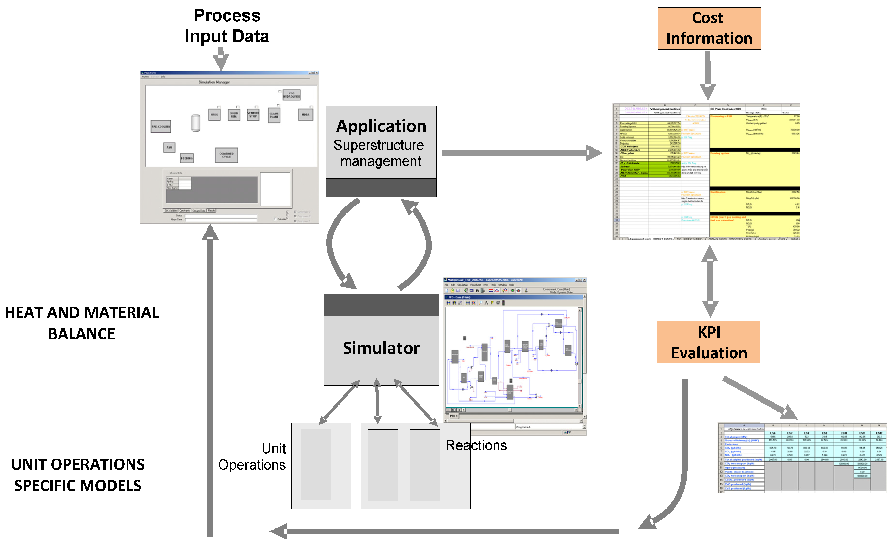
Figure 11 represents the information workflow of a generic process analysis.
The different flowsheet configurations are evaluated: scenarios approach, or mathematical modelling, (see Bojarski
et al. [
52] for further detail). KPI values can be depicted in Pareto Frontiers for comparison and configurations selection or prioritisation. Our developed evaluation tool utilises Aspen Plus as process simulator and MS Excel to process the KPI values. Particularly, for the co-combustion case study, the superstructure concept is applied to the selection of the most suitable pre-treatments (see next section). In that case, no process simulation has been performed. However, the superstructure concept applied to co-combustion plants would include the evaluation of different flue gas cleaning units and/or carbon capture materials.
The purpose of R&D in the IGCC power plants field is to improve the environmental performance, decrease marginal costs and investment and assure the technology availability/reliability. The idea that IGCC power plants are an opportunity is supported by the fact that nowadays, there are a lot of new projects envisaged around the world, mainly based on coal and located (in order of starting projects) in USA, Canada, China, and Europe. The report by Metz
et al. [
94] shows that Shell, Texaco and E-gas are demonstrating the real and practical interest of the concept. The main used technology is the Selexol capture system in pre-combustion configuration. New IGCC power plants with CO
2 capture technologies are included in the superstructure developed by the authors. Several works can be cited that measure the global performance of large scale gasification plants [
127].
Figure 11.
Flowsheet analysis workflow.
Figure 11.
Flowsheet analysis workflow.
The work by Hamelinck and Faaij [
87] evaluates technical and economic parameters of gasification plants to produce methanol and hydrogen, taking into account future prospects. Even if they have not developed a superstructure as understood in this work, they also use an Aspen Plus simulation to obtain energy and mass balances of interest for the economic evaluation. When large-scale production is of concern, biomass supply is an important item in operation costs when long distances should be covered. Hydrogen and methanol should be considered as conventional fuels alternatives; nevertheless the main bottleneck lies on the distribution infrastructure, mainly for hydrogen delivery. The work by Chiesa
et al. [
128] considers the production of hydrogen and electricity from coal; the authors evaluate different scenarios, considering CO
2 venting or CO
2 capture; electricity production with conventional gas turbines, with turbines for burning syngas and H
2, and with steam cycle (thus, pure H
2) as final syngas usages. Process intensification of acid species is also included by removing CO
2 and sulphur acid species in the same unit operation. They propose different analyses considering performance and emissions using simulation of real commercial units. In their economic analysis; performed by Kreutz
et al. [
129] , it is interesting to appreciate that one of the barriers found for a wide H
2 economy is the lack of a cost effective method of storage and the lack of a large interested market on it. Also the CO
2 storage capacity and CO
2 transportation have to be addressed in an efficient way to promote such a solution.
The specific issue of CCS in different plant types is tackled by Rubin
et al. [
130]. Natural gas combined cycle plant (NGCC), IGCC plant and PC plant are considered. It takes into account different possibilities of final transport and storage of CO
2: geologic, saline storage and enhanced oil recovery (EOR). They found, while comparing coal gasification and combustion with CCS, that costs are very sensitive to the coal quality. Moreover, depending on coal quality, PC plants or IGCC plants are the cheapest options among the three possibilities considered here, being IGCC plants the most penalised by the extra energy consumption from the CCS system. The most relevant contribution by Chen and Rubin [
90] is the consideration of uncertainty in the cost of CCS in an IGCC power plant by taking into account coal quality and CCS removal efficiency.
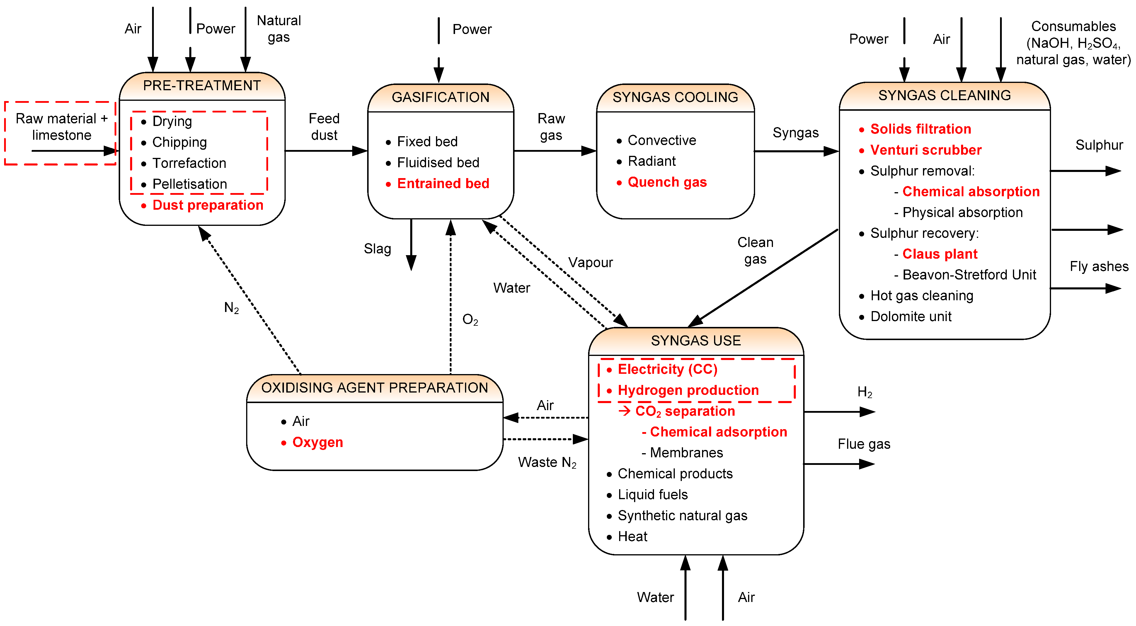
The complete IGCC-CCS superstructure is shown in
Figure 12. The diagram assembles all the technical possibilities that an IGCC plant offers. The options considered in our work are in red. Among all the options that a general IGCC plant offers to be optimised, the dashed lines in red indicate the design choices that are taken into account. Raw materials can be from different origins. Pre-treatment options include energy and matter densifications. Feedstock mixture and final syngas usage elections are carried out with MCDA. Note that in Aspen Plus we use stream splitters and mixers to perform the choice of different unit operations executing the same function in the process (see [
52,
131,
132]).
Figure 12.
IGCC-CCS superstructure. Dashed lines in red indicate the superstructure options considered. The modelled flowsheet in the process modeller, among the different unit’s alternatives, is highlighted in red (for more detail see [
131,
133]).
Figure 12.
IGCC-CCS superstructure. Dashed lines in red indicate the superstructure options considered. The modelled flowsheet in the process modeller, among the different unit’s alternatives, is highlighted in red (for more detail see [
131,
133]).
Hydrogen separated from the syngas may be used in different ways: (i) sold as a product; (ii) converted in fuel cells (if purified until their standards); or (iii) burnt in a gas turbine, as happens with syngas.
Figure 13 depicts the superstructure implemented by the authors (see Bojarski
et al. [
52]) to evaluate these possibilities. Concerning the splitting units used to model the superstructure, separation factors will allow the distribution of total or partial rates among the different technological options. Firstly, the choice whether combined cycle or H
2 needs to be done. Then, the purity of the H
2 in order to be sent to the turbine or to be sold to the market (
i.e., the use of PSA), is the variable to select. Co-generation of power and H
2 is one of the possible choices in the superstructure.
Figure 13.
CO2 capture and H2 production process superstructure.
Figure 13.
CO2 capture and H2 production process superstructure.
5. Bio-Based Supply Chain Modelling
It is recognised that in order to achieve the posed targets in the consumption of renewable energy (see
Section 1): (i) efficient networks to sustainable supply the amounts of biomass required; (ii) cost effective technologies to convert biomass and (iii) improved distribution infrastructures to deliver the final product (
i.e., energy or fuel) are to be developed [
134]. Moreover, the efficient integration of these three elements is equally relevant to achieve these targets. In this context, a supply chain modelling approach can be exploited as a tool that can support decision making towards accomplishing such integration.
The concept of supply chain (SC) refers to the network of interdependent entities (
i.e., processing sites, distributors, transporters, warehouses and raw material suppliers) which is the processing and distribution channels of a product from the origin of its raw materials to the final delivery to the customer. Then, supply chain management (SCM) can be defined as the management of material, information and financial flows through a SC that aims at producing and delivering goods or services to consumers [
135]. Notice that a SC is comprised by components that may be geographically distributed. One of the main objectives of SCM is to synchronise and coordinate the flows of materials that go through the different processes so that the final product is delivered in the most efficient manner. This is especially important for biomass to energy projects which are highly geographically dependent and whose profitability can be strongly influenced by the location of the different processes and biomass sources. Commonly, biomass production and transportation account for a significant part of the whole bioenergy supply chain cost [
136]. Therefore, a tool capable of evaluating the possible trade-offs between the different feedstock sources, each one with specific properties (
i.e., humidity and energy density) and the location of processing sites and consumption points is a requisite to develop efficient bioenergy networks.
Typically, a Biomass SC problem considers the possible use of multiple biomass sources from different origins that are geographically distributed, and the subsequent pre-treatment required to homogenise the material in mass and energy terms. These features imply the combination of different moisture contents (MC), dry matters (DM), lower heating values (LHV) and bulk densities (BD). Biomass, with high MC, low BD, low LHV and fibrous nature, may lead to biomass pre-treatment so as to optimise its transport, handling and treatment. Biomass properties can change along the SC.
In general, the major steps that a Biomass SC superstructure may include are (see
Figure 14):
Figure 14.
Schematic of a generic Biomass supply chain superstructure.
Figure 14.
Schematic of a generic Biomass supply chain superstructure.
Biomass growing, harvesting and collecting involve biomass production, by recovering biomass waste or using energy crops. Processes included here are drying, i.e., natural drying in the land field, baling or chipping. Resource seasonality determines the harvesting or collection period. Different seasonal sources mix and storage could mitigate the impact on supply continuity.
Biomass pre-treatment includes all the necessary steps to produce an upgraded fuel. Such fuel is homogeneous, has no impurities and is denser in terms of mass and energy. Pre-treatment allows costs reduction in biomass treatment, storage and transportation. Briquetting, pelletisation, torrefaction, pyrolysis, and combinations of them, are pre-treatment techniques [
59]. Research in biomass pre-treatment is crucial for the large scale biomass market.
Storage can be considered throughout the Biomass SC. Biomass can be stored whether before the transportation stage, at the biomass origin, in an intermediate step or at the power station site. This is crucial to create backups against seasonality. A drying phenomenon takes place here, even some dry matter loss may occur [
74]. Costs depend on the location and type of storage,
i.e., open air, roof covered, air fan, indoor storage. Their selection depends on climate conditions, shape and volume of biomass and time of storage [
23].
Distribution can be expensive due to the biomass low energy density. Costs depend on distance, speed, tortuosity, haulier's capacity and amount of biomass to be transported.
Biomass treatment refers to the biomass processing plant to produce the desired product, i.e., biofuels, bioproducts, heat, cool or electricity.
Next, we review some relevant works that have dealt with the Biomass SC problem from a quantitative perspective. The study by van Belle
et al. [
137] presents a qualitative and quantitative study of this first Biomass SC step, considering chipping, central storage of the wood residues and intra-land transport. The harvesting or collection period depends on the seasonality, thus facing with an amount of fuel that can be discontinuous during the year. Hamelinck
et al. [
138] considers an international bioenergy SC taking into account the fact that biomass production and consumption do not need to be in the same region. Biomass compacted to briquettes or pellets can be used to save in distribution costs since they present a higher density. Nevertheless, there exists a trade-off between the distribution cost, the distance and the densification methods. This is important to consider especially when long distances should be covered. They demonstrate that an international bioenergy trade has real potential; however, improvements in terms of prices, policies and social acceptance are necessary. Panichelli and Gnansounou [
136] contemplate forest wood residues (FWR) from final cuttings to produce torrified wood that supplies a gasification unit in order to produce electricity. They are able to allocate biomass quantities between predefined combinations of candidate sites to find the best set of locations for the energy units. They fix values for the torrefaction and gasification units, and take into account cost minimisation. A mixed integer linear program (MILP) that determines the optimal sizes and locations of biomass-based methanol plants (biofuel plants) is developed by Leduc
et al. [
139]. The objective function to be optimised is the operating costs and the investment required to establish the Biomass SC. The supply is given by poplar coppice, as energy crop, and the demand is based on gasoline-methanol car blend use. The possible consumer sites are the already existing gas stations in Austria, while methanol production is considered through the use of gasification plants. By-production of heat is also considered as economic revenue, and CO
2 emissions are accounted finally, but not introduced in their model as an environmental objective to be accomplished. The work of Rentizelas
et al. [
74] emphasises the multi-biomass seasonal availability and combines this fact with the biomass storage problem. The stages considered before the conversion plant of the raw material include harvesting and collection, in field handling and transport, storage, loading and unloading, transport, and biomass pre-treatment. This last stage can be included in any of the abovementioned stages, and could precede the transportation stage. Storage can be also located in the biomass origin in an intermediate step or at the power station site. The authors state that one of the main drawbacks of the use of biomass as a source, is its relatively low density and heating value when compared for instance with other fossil sources. On a later work, Rentizelas
et al. [
140], exemplify the fact that a biomass SC can account for multiple sources, as well as for multiple final products production, such as electricity, heat and cooling. They apply the methodology in a specific region of Greece. The results provide with optimal locations and investment details for potential investors. The works by Zamboni
et al. [
141,
142] formulate a MILP model to minimise operating costs and GHG emissions of a biofuel SC. The second work performs a multi-objective optimisation by taking into account the whole SC, from biomass cultivation to fuel distribution. The region under study is discretised into a grid of square regions to map the network and to estimate the biomass cultivation potential for each region. Using as starting point the formulation developed in Zamboni
et al. [
141], Akgul
et al. [
143] also minimise costs, while decreasing calculation time including spatial restrictions through a “neighbourhood” flow limitation. Elia
et al. [
144] uses a MILP multi-objective optimisation to propose a sustainable SC for a novel hybrid concept for a plant that produces liquid fuels,
i.e., gasoline, diesel and kerosene, using coal, biomass or natural gas as main feedstocks. The authors conclude that the hybrid configuration (fossil fuels—biomass) allows for competitive biofuels prices. Zhang
et al. [
145] adopt a GIS-based method to find the best location for a biofuel plant, based on the distributed nature of the woody biomass sources and the associated transportation costs. The methodology comprises two steps: location of site candidates and selection of the cost-optimal area. The paper by Chiueh
et al. [
146] uses GIS to identify the biomass waste resources and the specific transportation routes for a co-combustion retrofitting problem, evaluating different levels of pre-treatment (torrefaction) centralisation.
Undoubtedly, energy policies are partially driven by environmental considerations, more specifically by the pressure on reducing greenhouse gas (GHG) emissions. Biomass is an energy source that is expected to provide significant reductions of environmental impacts related to GHG emissions when compared to the classical fossil fuels technologies. Therefore, it is relevant the integration of environmental thinking into SCM in order to assess such expected reduced environmental impacts. The aforementioned integration may be achieved through the concept regarded as “Green Supply Chain Management” (GrSCM). This concept considers the environmental interventions associated with the raw materials sourcing and selection, manufacturing process selection, delivery of final product to the consumers as well as end of life management of the product after its useful life [
147]. Traditionally, the methodologies devised to assist SC operation and design have focused on finding a solution that maximises a given economic performance indicator while satisfying a set of operational constraints imposed by the manufacturing/processing technology and the topology of the network. In recent years, however, there has been a growing awareness of the importance of including environmental aspects as objectives and not only as constraints associated with the SC decision support [
148,
149].
The environmental science and engineering community have developed several systematic methodologies for the detailed characterisation of the environmental impacts of chemicals, products, and processes. All of these methodologies have embodied the concepts of life cycle,
i.e., they are based on a LCA which is described in a series of ISO documents [
150]. The LCA framework includes the entire life cycle of the product, process or activity, encompassing extraction and processing of raw materials; manufacturing, transport and distribution; re-use, maintenance recycling and final disposal. Most importantly, it takes a holistic approach, bringing the environmental impacts into one consistent framework [
151]. The idea is to determine process conditions or topology using a multi-criteria optimisation strategy in order to evaluate the trade-off between economic and environmental issues.
As aforementioned, the concept of SC refers to the network of interdependent entities that constitute the processing and distribution channels of a product from the supply of its raw materials to its delivery to the final consumer. Because an LCA study ideally covers a cradle-to-grave approach, it can be clearly seen that LCA fits as a suitable tool for quantitatively assessing the environmental burdens associated with designing and operating a SC.
Cherubini and Stromman [
152] review works in the field of LCA of bioenergy systems, concluding that most studies found a reduction in GHG emissions and in fossil fuel energy consumption. Nevertheless, even if the LCA follows a well-established methodology, the selection of the functional unit (FU) changes according to authors criteria (for instance, power produced or energy/mass flowrates of biomass introduced into the system) and makes it difficult the comparison among different works. Damen and Faaij [
75] presents a life cycle inventory of a biomass-based SC for co-firing. This work compares a biomass co-use plant with a 100% coal power plant. The net avoided primary energy and GHG emissions are significantly reduced in the biomass co-use plant. Perry and Rosillo-Calle [
61] treat exhaustively the subject of CO
2 emissions along the whole SC, considering emissions from production, conversion, distribution and land use displacement caused by the modification of the biomass use. Ayoub
et al. [
153] present a methodology for designing and evaluating the biomass utilisation networks (so called B-NETs), which are process networks aiming at producing different bio-products, from one or more biomass resources. The idea of this methodology is to provide a framework to create the underlying superstructure that relates the biomass resources to their products via current and possible future available processes, which can be used to develop an optimisation model. Their methodology is applied at a local level and proposes better biomass uses by means of economic parameters (costs) and environmental impacts accounting. The environmental indicator that the authors use accounts for emissions to air, water pollutants and solid wastes. Later on, Van Dyken
et al. [
154] develop a linear optimisation model for planning the capacity expansions in energy systems where several alternative biomass and technologies are considered simultaneously. The main objective of this work is to present a generic model including different component such as sources, handling, processing, storage and final usage. Heating value, moisture content and bulk density are the key parameters changes that biomass undergoes along the SC. The objectives to be optimised are the operating cost and emissions of the whole SC.
The review by Cambero and Sowlati [
155] remarks that the use of biomass has an important potential to substitute fossil fuel, while all three aspects of sustainability (economic, environmental, and societal) have to be considered in the optimisation problem. Tavares
et al. [
156] use GIS to identify the most suitable locations for municipal solid waste plants, according to socio-economic, technical and environmental criteria. Pérez-Fortes
et al. [
39] optimise a decentralised biomass problem that uses cassava waste as raw material to power a gasifier—gas engine plant. This problem considers MO optimisation with three criteria: economic, environmental and social. Employment generation is used as social criteria. The developed MILP allows the selection of: (i) optimum flow rates, sites connectivity and capacity of units; and (ii) the best technology to be employed from a superstructure of technological options for biomass processing as shown in
Figure 15. The algorithm developed in this work is the starting point of the work of Pérez-Fortes
et al. [
157]. In this work, the MILP program is adapted to solve a SC problem in Spain that considers biomass waste to fulfil the biomass required to replace a portion of the power in the current coal power plants installed.
From another standpoint, uncertainty has been increasingly considered when modelling biomass SC's: Shastri
et al. [
158] points out the seasonal and distributed origin of biomass in its BioFeed MILP model which is developed to optimise a farm,
i.e. the biomass collection step. Gebreslassie
et al. [
159] also models a stochastic MILP program to address the optimal design of a biorefinery SC under supply and demand uncertainties, a risk management optimisation approach is presented. In Osmani and Zhang [
160], a stochastic MILP model is developed, considering uncertainty in the supply of biomass-to-bioethanol, demand of biofuel, biomass and biofuel prices, with the purpose of determining the location and the efficiency of the biorefineries on the one hand, and the connections and storage sites, until the bioethanol is sold, on the other. Recently, Yilmaz, Balaman and Selim [
161] design an anaerobic digestion SC, under cost and environmental criteria optimisation considering uncertainties. In this case, the method employed is a Fuzzy MO-MILP.
Figure 15.
Superstructure utilised for the Biomass SC model presented in Pérez-Fortes
et al. [
157].
Figure 15.
Superstructure utilised for the Biomass SC model presented in Pérez-Fortes
et al. [
157].
High complex and computational demanding programs are resulting from the development of MILPs for the evaluation of biomass related SC’s, thus calling for decomposition methods that can attenuate the heavy computational load that is needed for the solution of biomass SC related programs. The article from Osmani and Zhang [
160] employs a decomposition based on the Sample Average Approximation method. Gebreslassie
et al. [
159] utilises the Multicut L-shaped method, while the work by Shastri
et al. [
158] uses a Decomposition scheme together with a Distributed Computing approach. More recently, Laínez-Aguirre
et al. [
162] propose a Lagrangian relaxation based approach, the Optimal Condition Decomposition (OCD), to tackle medium size models which require intensive computational power. The methodology is applied to solve the biomass SC case study located in Spain, previously studied in Pérez-Fortes
et al. [
157].
The aforementioned works demonstrate that biomass supply modelling has become a research area of great interest since it provides a tool that supports strategic and tactical decision making which is vital to configure the highly geographical distributed biomass networks. These works point that the necessity of also considering environmental and societal aspects during the evaluation of Biomass SC projects. The main issues that still require further effort and should be overcome are the consideration of seasonality and heterogeneity, in terms of biomass properties and sources. Overall, traditional techniques of mathematical programming for SC modelling have a new challenge in the treatment of biomass properties along the chain. The mathematical models resulting from the Biomass SC are of significant size involving thousands of variables and constraints. Initial efforts have been devoted to develop decomposition techniques in order to make real size problems tractable. However, there are still many challenges in this arena and the application of decomposition techniques is an area that deserves further investigation.


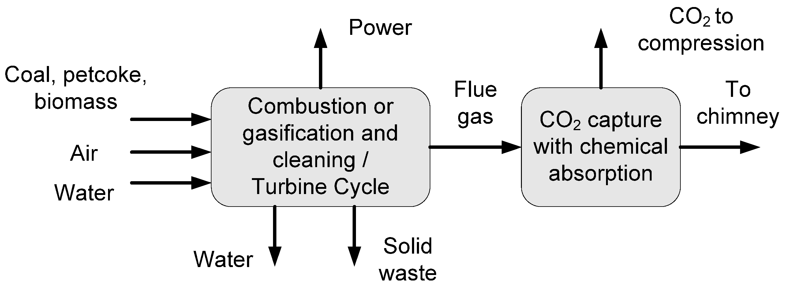


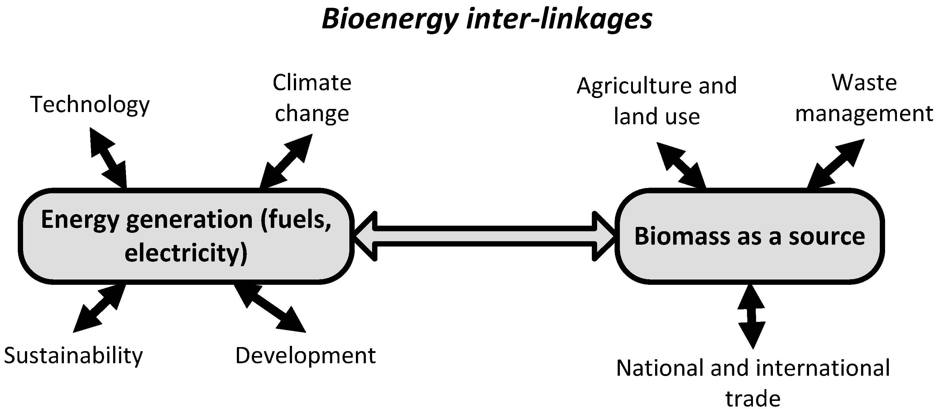
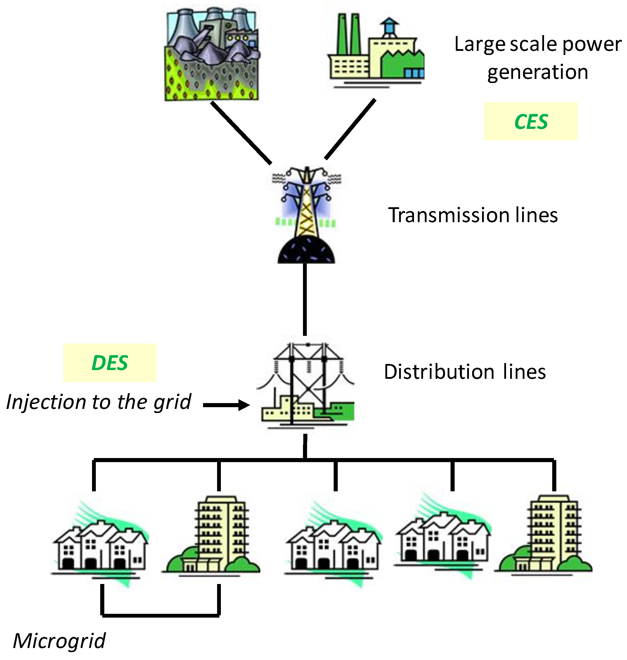
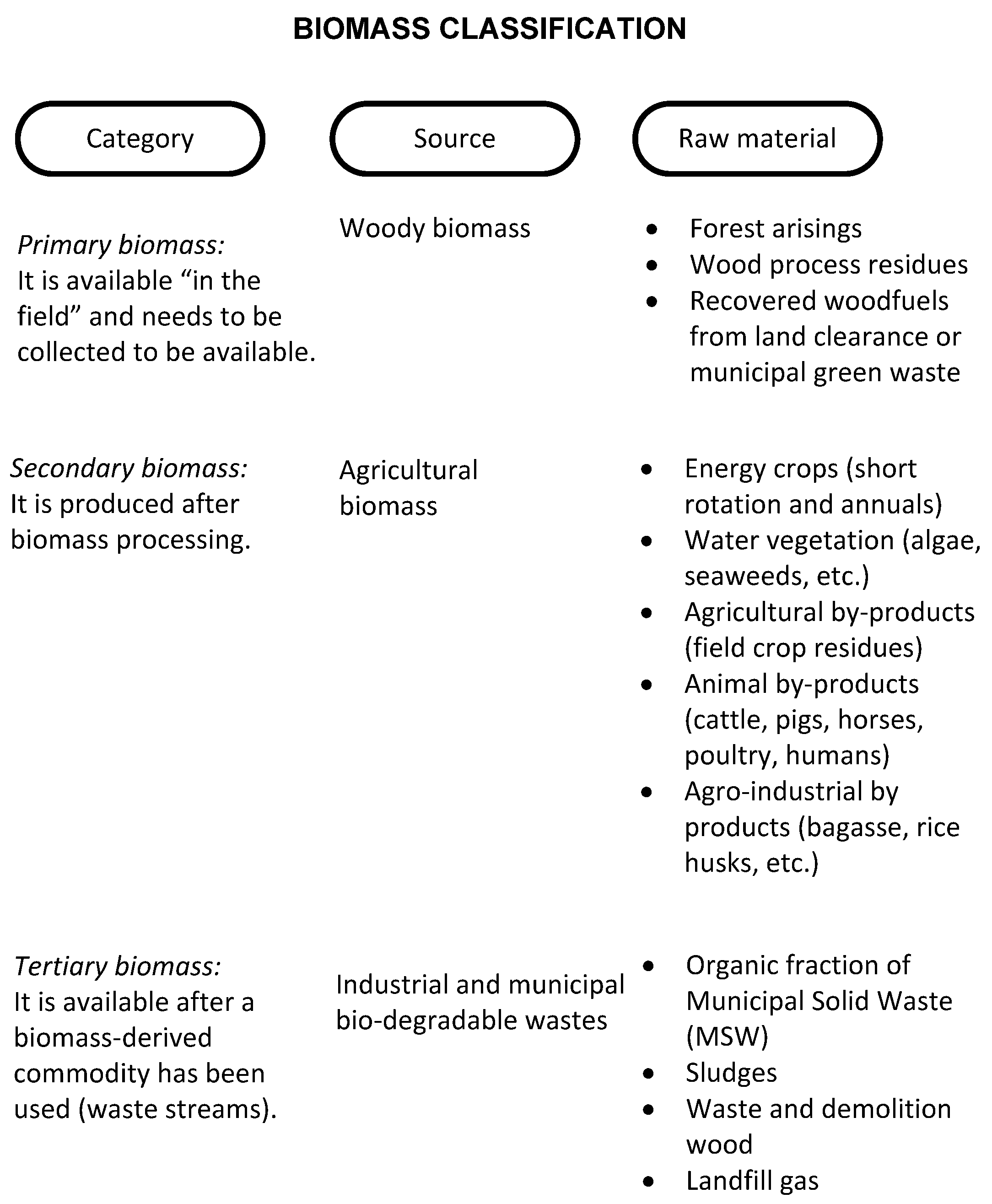
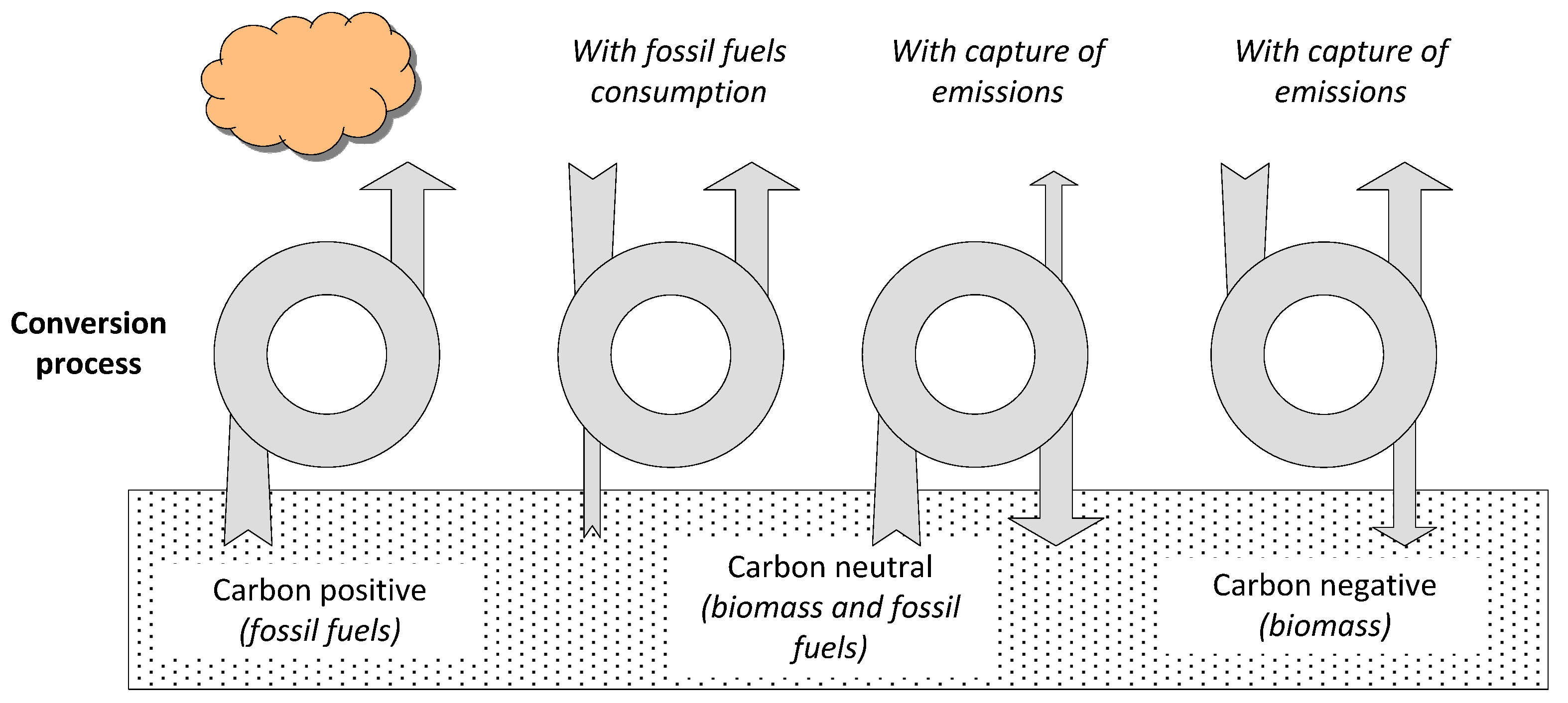
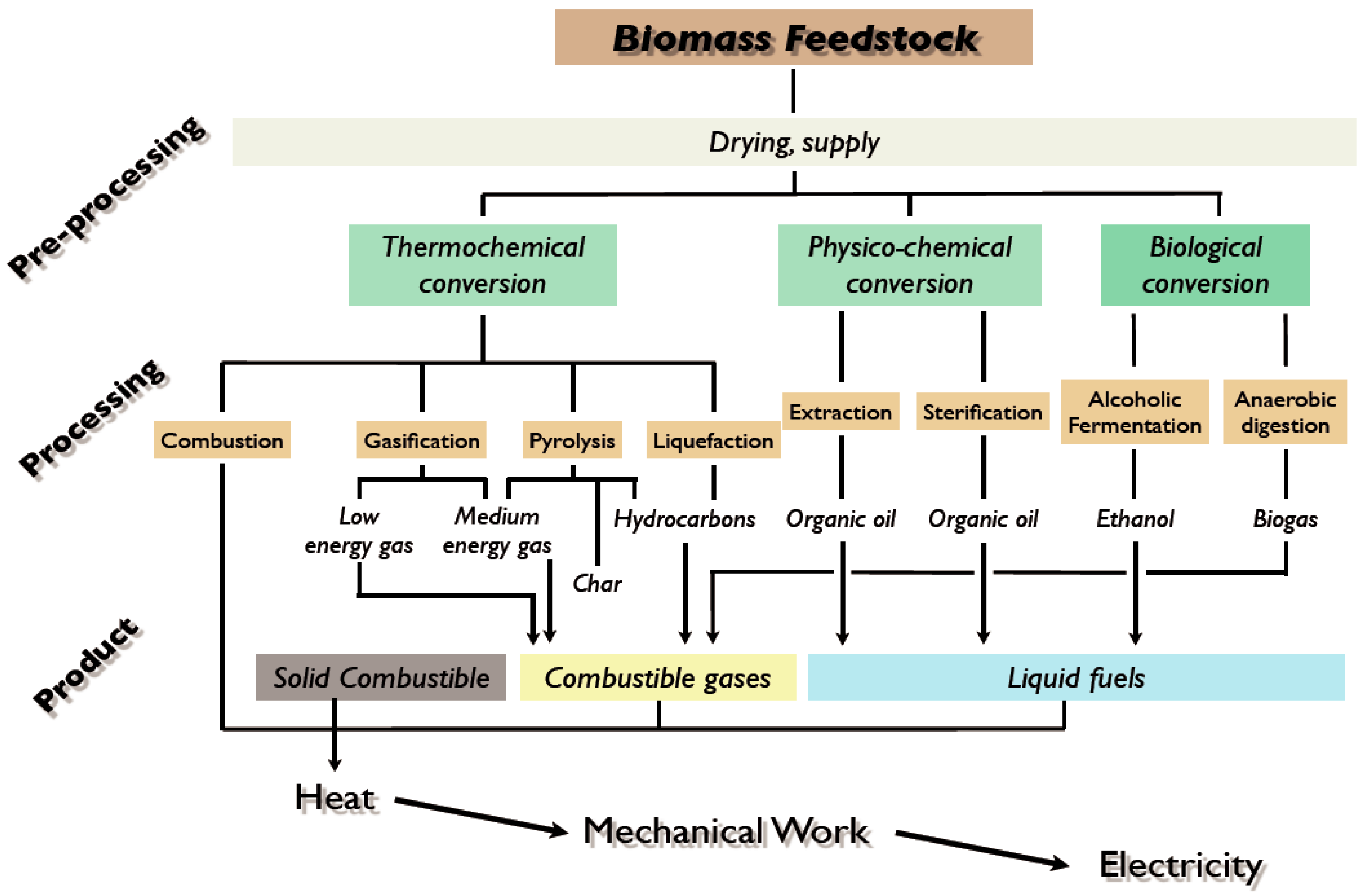
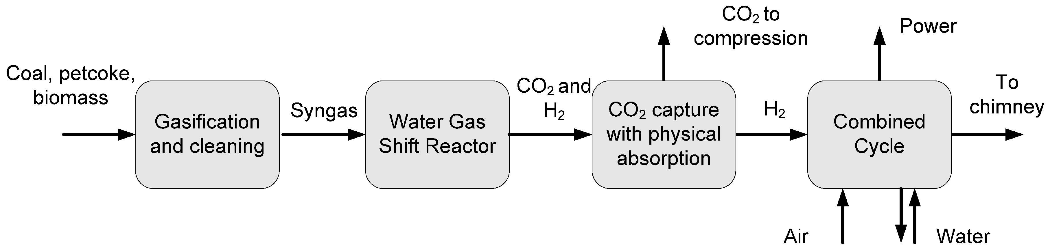
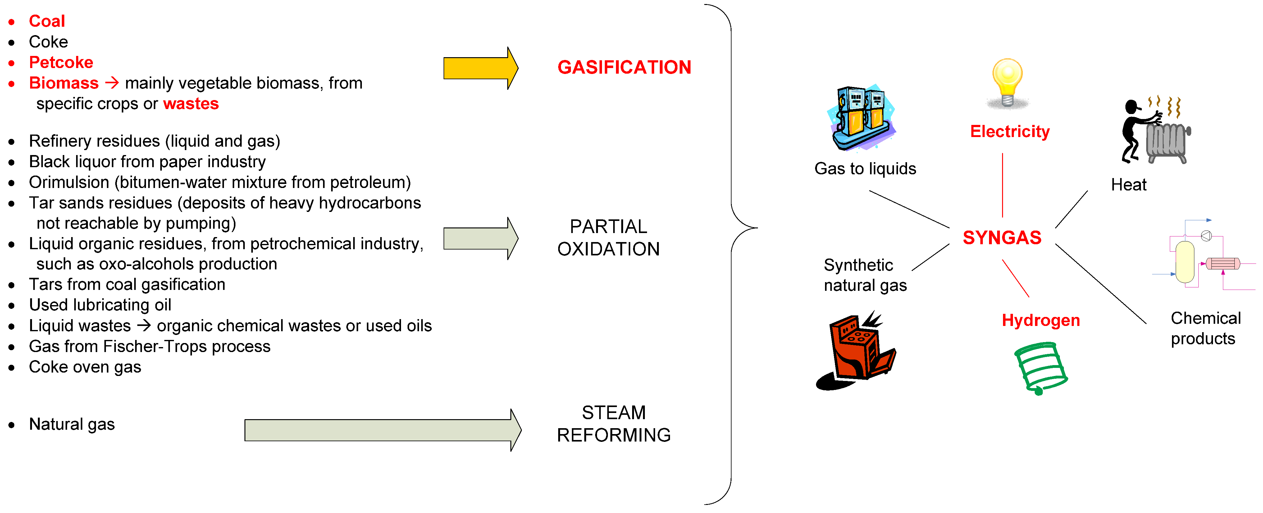
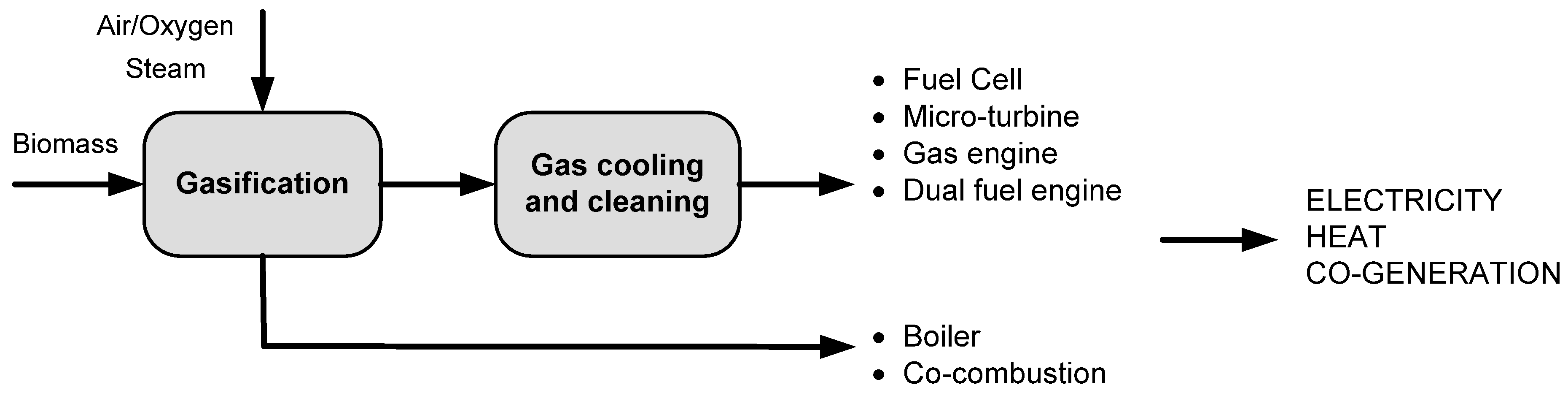
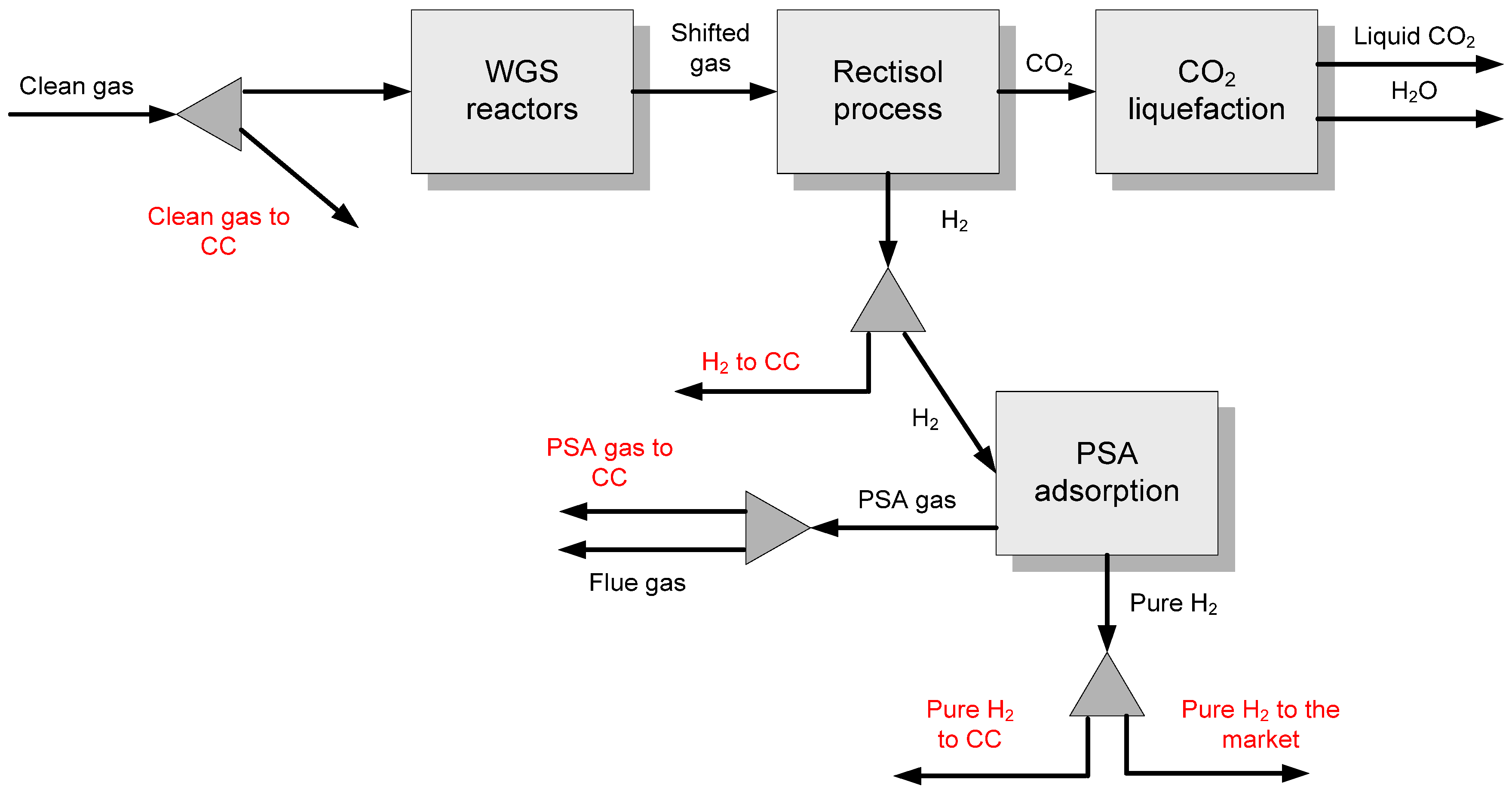
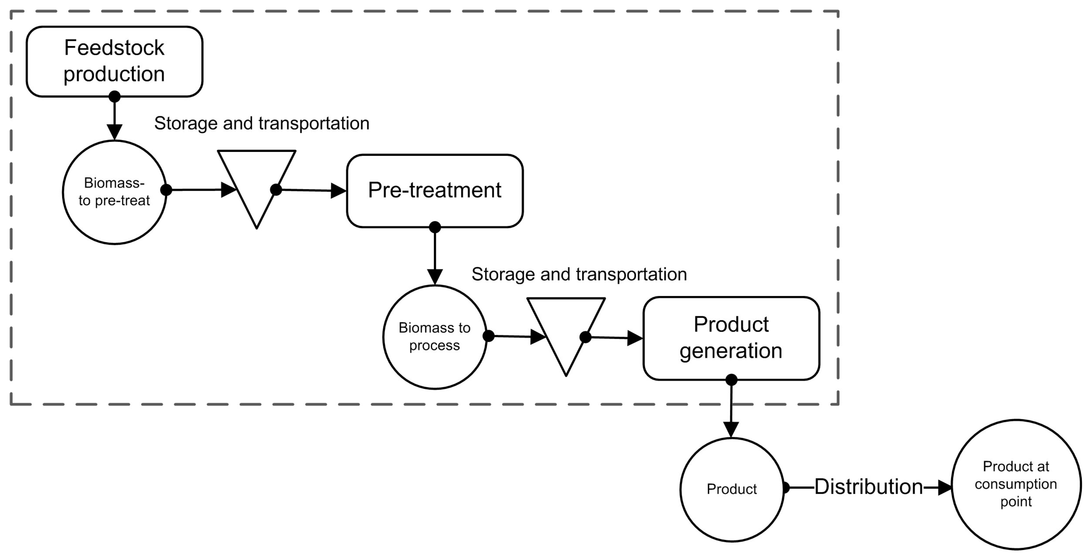
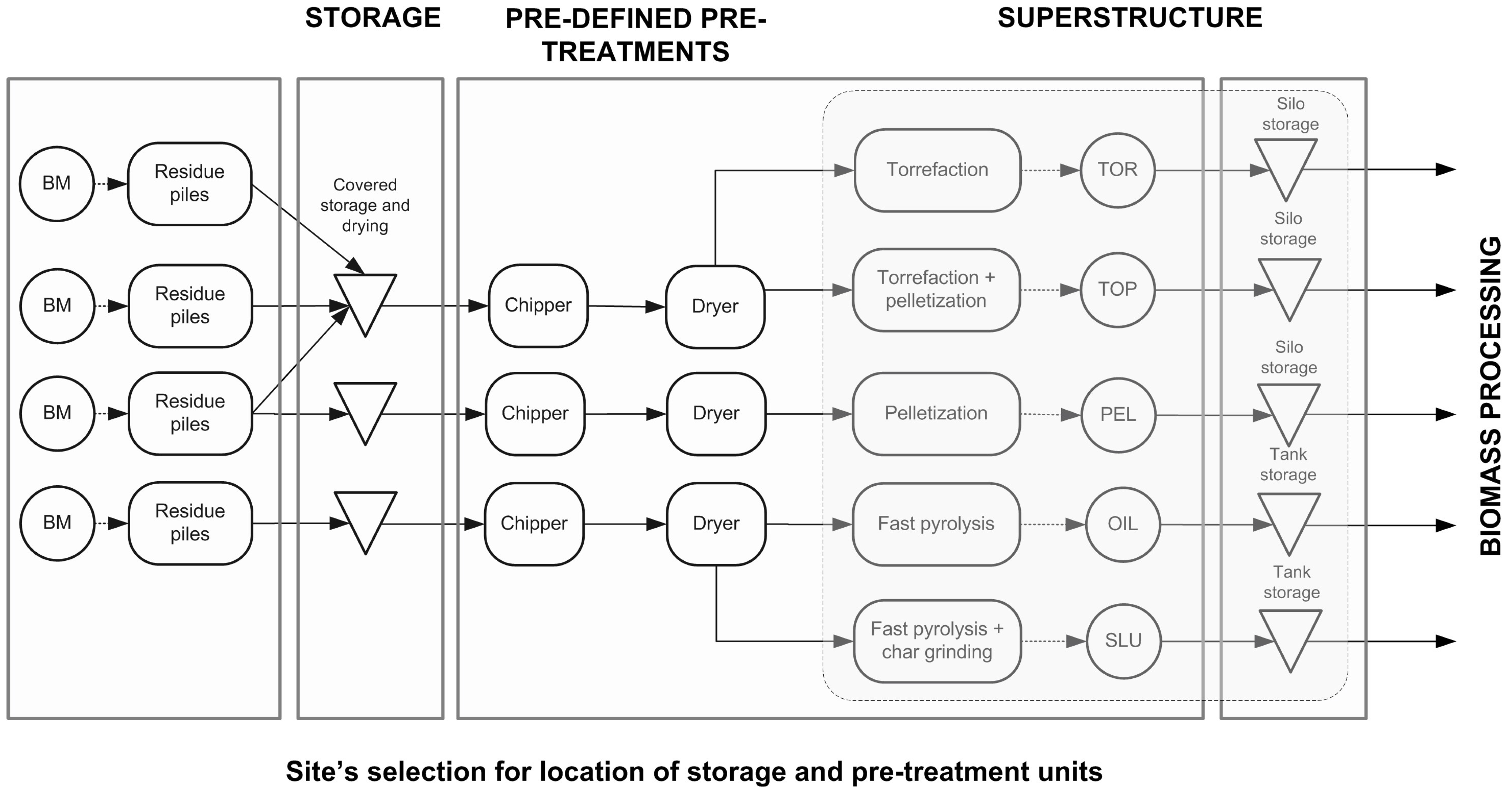