Article

Analysis and Design of a Permanent Magnet Bi-Stable Electro-Magnetic Clutch Unit for In-Wheel Electric Vehicle Drives

State Key Laboratory of Advanced Electromagnetic Engineering and Technology, School of Electrical & Electronic Engineering, Huazhong University of Science and Technology, Wuhan 430074, China
*
Author to whom correspondence should be addressed.
Energies 2015, 8(6), 5598-5612; https://doi.org/10.3390/en8065598
Submission received: 9 March 2015 / Revised: 29 May 2015 / Accepted: 1 June 2015 / Published: 11 June 2015
(This article belongs to the Special Issue Electrical Power and Energy Systems for Transportation Applications)

Abstract

:
Clutches have been used in internal combustion vehicles and concentrated electric vehicles (EVs) to smoothen impulsion while starting and shifting. This paper proposes a permanent magnet bi-stable electromagnetic clutch unit (PMBECU) which is specially introduced into in-wheel EVs to make the rigid connection between hub and wheel more flexible. Firstly, the operation principle of the PMBECU is illustrated. Then, the basic magnetic circuit model is presented and analyzed, followed by optimal design of the main structural parameters by investigating the PM leakage flux coefficient. Further, according to the basic electromagnetic characteristics of the PMBECU, the current pulse supply is put forward, and the minimum pulse width which enables the operation of the PMBECU and its dynamic characteristics are analyzed by an improved finite element method. Finally, a prototype machine is manufactured and tested to validate all the analysis results.

1. Introduction

Electric vehicles (EV) have been intensively investigated recently as potential solutions for the growing problems of the energy crisis and environmental pollution [1,2,3,4], focusing on the drive form, electric motor, controller, battery, energy system, drive comfort, etc. Compared with centralized drive, the in-wheel EV drive is considered the more competent drive form for EVs in the near future [5,6,7], because of its merits of direct drive (no-gearbox), more flexible control strategy (torque at each wheel is independently controlled), high mechanical integrity (greatly different from conventional gasoline cars). However, the rigid connection between hub and motor, inevitably introduces mechanical shocks and electromagnetic impulsion during sudden start and stop processes, which can potentially harm the motor and controller and reduce drive comfort [8,9,10].
Referring to traditional gasoline cars, this electromechanical impulsion in in-wheel EV drives can be ameliorated by introducing a clutch between the hub and motor to make the rigid connection more flexible [11]. The simulation and experimental results of a conventional clutch between motor and load presented in [12,13] show that the starting current and jerk in clutch coupling starts under different idle speeds can be reduced to less than 1/2 compared to direct starting, and the impulsive back electromotive force to the controller can be eliminated by detached braking (the motor stops naturally after being disconnected from the braking load). Besides, in hybrid EVs, the conventional clutch has been used to cut off the engine or electrical machine while idling to avoid spin losses and extend the life cycle of the machine [14]. Moreover, in in-wheel driven EVs, clutches have been used to detach the motor from hub to reduce losses while coasting [15].
However, the conventional mechanical clutch system [16,17] is not suitable for the limited space available in a hub and suffers from a need for regular maintenance which makes it unsuitable for in-wheel EV drives. In addition, electromagnetic clutches [18,19], which can be easily manipulated by current control, are energy-consuming and also suffer from the problem of accommodating their shape in the hub. In other clutches [20] one encounters one or all of the aforementioned problems, thus are also not suitable options.
This paper proposes a permanent magnet bi-stable electromagnetic clutch unit (PMBECU), which is controlled by current and held by the PM in a steady state, and thus is energy-saving, and it also has a flat structure that makes its placement in a limited space viable. The clutch system is realized by assembling several PMBECUs around motors, combined with friction or jaw pairs.
As key parts of the clutch system, this paper focuses on the electromagnetic design and analysis of the PMBECU. The design and analysis of linear electromagnetic devices, such as electromagnetic valves [21], electric tools [22], oscillators [23,24], and switch gears [25,26,27], are mainly carried out by the finite element method (FEM). Likewise, aiming to satisfy the need to accommodate the clutch in the limited space available in the hub, the optimal design of the main structure parameters of the PMBECU are carried out by FEM which focuses especially on investigating the leakage flux coefficient of the PM. Moreover, in order to realize simple and reliable control of the operation of the PMBECU, the dynamic characteristics of the PMBECU are calculated by improved FEM, which shows that the low power capacitor pulse supply is very suitable. The influence of the temperature on the dynamic performance is also analyzed. The analysis method and results are finally validated by measurements taken on a prototype machine.

2. Operation Principle

The assembly of the PMBECUs to realize the flexible connection between hub and motor is shown in Figure 1a, and the structure of the PMBECU, in which two PMs with opposite polarities are mounted on each side of a rigid E-type ferromagnetic base, is shown in Figure 1b. The ferromagnetic mover is placed in two low-frictional slideways which are non-magnetic. Two coils are connected n series and wound around each slideway.
Figure 1. (a) Flexible connection of hub and motor; (b) Structure of the PMBECU.
Energies 08 05598 g001
The 2-dimensional (2D) analysis model of the PMBECU with its main structure parameters labeled is shown in Figure 2, where the right direction is prescribed as positive for force and movement variables.
Figure 2. 2D analysis model of the PMBECU.
Energies 08 05598 g002
The flux line distribution of the PMBECU without current injected into the coils is shown in Figure 3a. Apparently, the mover is held by the left PM in a steady state without energy consumption. When current with a suitable orientation (i.e., the current direction shown in Figure 2) and value accesses the coils, the mover is polarized, and the corresponding flux lines distribution is shown in Figure 3b. The mover will soon be propelled from the left steady state to the right by the resultant electromagnetic force. Meanwhile, the current is switched off automatically by the position sensor, and the mover is held by the right PM, again without any energy consumption, thus it is bi-stable.
Figure 3. Magnetic flux lines distribution. (a) Steady state; (b) Action.
Energies 08 05598 g003
It is evident that the PMBECU has a flat structure thus is suitable for placement in a limited space, and the switchover between engagement and disengagement is electrically-controlled thus it can be conveniently manipulated, and only an instant current is required for switchover, but most time it is in a steady state which is held by a PM and thus is energy-saving.

3. Electromagnetic Design

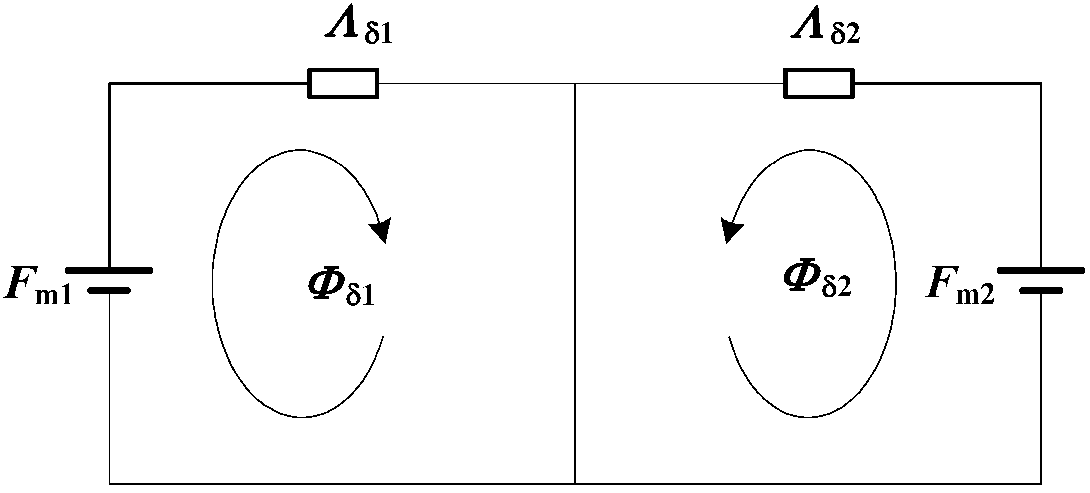
3.1. Magnetic Circuit Model

According to the magnetic flux line distribution shown in Figure 3a, assuming the ferromagnetic material has infinite permeability and neglecting the contact air gaps, the magnetic circuit relations of the PMBECU under open circuit of the coils conditions can be expressed by a simplified magnetic network as shown in Figure 4.
Figure 4. Simplified magnetic network.
Energies 08 05598 g004
The magnetic network comprises two independent branches, where Fmj (j = 1, 2), Λδj, and Φδj are the magneto-motive force furnished to the air gap by the PM, air gap permeance, and magnetic flux pass through the pole face of the mover at each side, which are calculated by Equations (1)–(3), respectively:
F mj = H c h m δ j ( k σj h m μ r + δ j )
Λ δj = μ 0 S m δ j
Φ δj = B r S m ( k σj + μ r δ j h m )
where Br, Hc, and μr are remanence, coercivity, and relative permeability of the PM, hm and Sm are the thickness and pole face area of the PM, δj is the air gap length as labeled in Figure 2, μ0 is the permeability of air, and kσj is the leakage flux coefficient which is defined as:
k σj = Φ mj Φ δj
where Φmj is main magnetic flux through bottom face of PM.
The Maxwell stress tensors are given by the following equation [27]:
t n = ( B n 2 B s 2 ) / ( 2 μ 0 ) t s = B n B s / μ 0
where Bn, Bs are the outer normal and tangential components of the flux density on the mover, respectively. Out of an infinite permeable surface, the flux density only has a normal component. Hence, combined with Equation (3), the holding force (horizontal) at steady state (δ1 = 0, δ2 = lt, lt is the travel length of the mover) can be approximately calculated by:
f H = B δ 1 2 S m 2 μ 0 B δ 2 2 S m 2 μ 0 = B r 2 S m 2 μ 0 ( 1 1 ( k σ 2 + μ r l t h m ) 2 )
With forces normalized to fb = 0.5Br2Sm0 (the same hereafter), the holding force is:
f H = 1 1 ( k σ 2 + μ r l t h m ) 2
Apparently, the holding force of the PMBECU is determined by kσ2 (leakage coefficient at δ = lt), the ratio of travel length to thickness of the PM lt/hm, and the PM characteristics. Moreover, the leakage flux coefficient kσ2 is a function of the structure parameters, and can be calculated by Equation (4) after the magnetic flux derived from FEM analysis.
By increasing the current from 0, the electromagnetic force experienced by the mover can be obtained, and then the ideal threshold current iT which critically enables the action of the mover can be obtained by FEM as well, corresponding to the horizontal electromagnetic force fmx = 0. In this paper, current is all normalized to ib = Hchm/N, where N is the number of turns for one coil.

3.2. Main Structure Parameters Design

The PMBECU works at steady state most of the time, which is reliably maintained by the holding force, thus the holding force is the most significant index. According to Equation (7), the leakage flux coefficient kσ2 at the detached side, which is a function of the structure parameters, has a great influence on the holding force. Moreover, the leakage flux coefficient determines the reasonable usage of the PM. Thus, the main structure parameters (as labelled in Figure 2), i.e., the width of the PM wm, the height from the PM to the base hp, and the travel length of mover lt, are optimized by studying kσ2, combined with accounting for the holding force and threshold current, where, other size ratios (proportioned to hm) remain unchanged while one varies the parameters within the ranges hp/hm = 1.2, wm/hm = 2.5, lt/hm = 2.
The variation of kσ2 versus different structure parameters is shown in Figure 5. Figure 5a shows that the leakage flux coefficient increases quite slowly when hp is 1.5 times bigger than hm, hence hp would better be within 1–1.5 times of hm, which also indicates the PMBECU is capable of a flat structure. Likewise, wm would better be around 2.5 times of hm as seen in Figure 5b. Figure 5c shows the leakage flux coefficient kσ2 increases almost linearly with lt, which shows no clear inflection point. But from Figure 5d, the holding force increases very slowly when lt is 2 times larger than hm, meanwhile, the threshold current keeps increasing, which makes the action of the mover harder. Hence, lt within 1.5–2 times the thickness of the PM is more sensible.
Figure 5. Opimization. (a) Height from PM to base; (b) Width of PM; (c) Travel length; (d) Travel length.
Energies 08 05598 g005

4. Dynamics Analysis

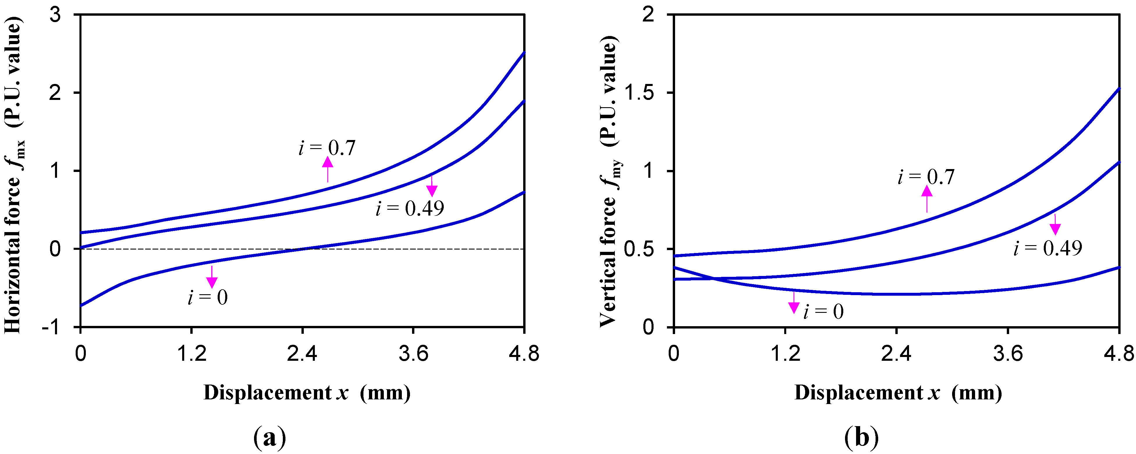
4.1. Electromagnetic Characteristics

Based on the aforementioned analyses, a PMBECU prototype designed with the main parameters listed in Table 1 is shown in Figure 6. Assuming the mover is fixed at different positions, changing the current (constant DC wave) in the coil, computing the magnetic field by FEM and the forces experienced by mover by (5), then the electromagnetic forces on the mover versus current i and displacement x are obtained as shown in Figure 7.
Table 1. Leading design parameters.
ParameterValueParameterValue
Thickness of PM hm2.5 mmWidth of base wb80 mm
Width of PM wm6 mmRemanence of PM Br0.4 T
Length of PM lm20 mmCoercivity of PM Hc318 kA/m
Height of PM to base hp3 mmTurns of coil N60
Travel length lt4.8 mmMass of mover m56 g
Figure 6. Prototype.
Energies 08 05598 g006
From Figure 7a, for open circuit conditions, the i = 0 horizontal force curve indicates that the PMBECU has two steady states held by the magnetic force from the PM, and an unstable equilibrium point (the half travel length location). When the mover exceeds this unstable point, the mover can be drawn to the other steady state automatically even if the current is switched off. Since the current increases to the ideal threshold current (enabling the action of the mover) i = 0.49, the mover starts moving. The maximum current in the coil is limited by the inflection point of the demagnetizing curve of the PM (critical point of irreversible demagnetization), which is i = 0.77 in this prototype.
In fact, because of the asymmetric structure in the vertical direction, the mover experiences a downward vertical electromagnetic force (as shown in Figure 7b) which introduces frictional resistance. Hence, accounting for friction, and other errors (material, model, measuring, etc.), the real threshold current iT is bigger than the calculated value, which is iT = 0.52 for the prototype. Moreover, to guarantee the performance of the PM, the maximum current should be limited to iM = 0.7.
Figure 7. Electromagnetic forces. (a) Horizontal; (b) Vertical.
Energies 08 05598 g007
When the current is larger than the threshold current, the resultant positive horizontal force starts to drive the mover, and the force is a monotonously increasing function of the displacement. After moving through the middle point of the PMBECU, the mover can reach another steady state with the current switched off (i.e., the pulse current sustains only half the travel length width). What’s more, considering the inertial motion and variation of the kinetic friction coefficient, the pulse width of the current can be even smaller. Thus, a dynamics analysis of the PMBECU should be carried out.

4.2. Dynamics Equations and Analysis Method

Because of the motion symmetry of the PMBECU, only the movement of the mover from left to right is investigated. Supposing the static friction coefficient is equal to the kinetic friction coefficient, then the magnetic-kinematic coupled mathematic equations which determines the dynamics characteristics are described as:
f mx f z = m d v d t
v = d x d t
f mx = q ( x , i ) , f my = p ( x , i )
f z = μ s ( f my + m g )
where fmx and fmy are the horizontal and vertical electromagnetic forces on the mover, fz is the resisting force, v is the velocity of the mover, μs is the static friction coefficient which is 0.065 in this prototype (measured), and g is the acceleration constant of gravity.
The dynamics analysis of the PMBECU is to illustrate the coupling of the magnetic field and the movement. To cope with the varying friction resistance conditions of the PMBECU, and give consideration to the convenience of analysis of varied structure sizes, an improved FEM is proposed. As shown in Figure 8a, two lt length rectangular areas (namely, the material variation area) in proximity to the PMs are established and uniformly meshed into n steps of quadrilateral shape, i.e., the step length is Δx = lt/n. The initial permeability of the left part and the right are set as iron (μFe) and air (μ0) respectively. As shown in Figure 8b, if the permeability of the first Δx meshes in the left material variation area is changed into μ0 and the first Δx meshes at the right into μFe, a Δx displacement of the mover is equivalently realized. Thus, a onetime mesh can cover the travel length displacement of the mover [23].
Figure 8. Onetime mesh technique. (a) Mesh; (b) Principle.
Energies 08 05598 g008
Further, by setting displacement as a known quality but time as an unknown variable, and calculating the time, velocity, and current before each time of material variation, the whole PMBECU movement process (i.e., the dynamics characteristics of the PMBECU) can be solved by using only a onetime mesh. This improved FEM analysis flow chart is shown in Figure 9, where both the current change and resistance variation can be taken into account, which can be easily realized by commercial FEM software (e.g., ANSYS programmable design language). In this paper, at each side of the mover, the front part of the material variation area is finely meshed and the rear part is roughly meshed (because the front part of displacement takes much more time), so as to improve accuracy and reduce the amount of computation.

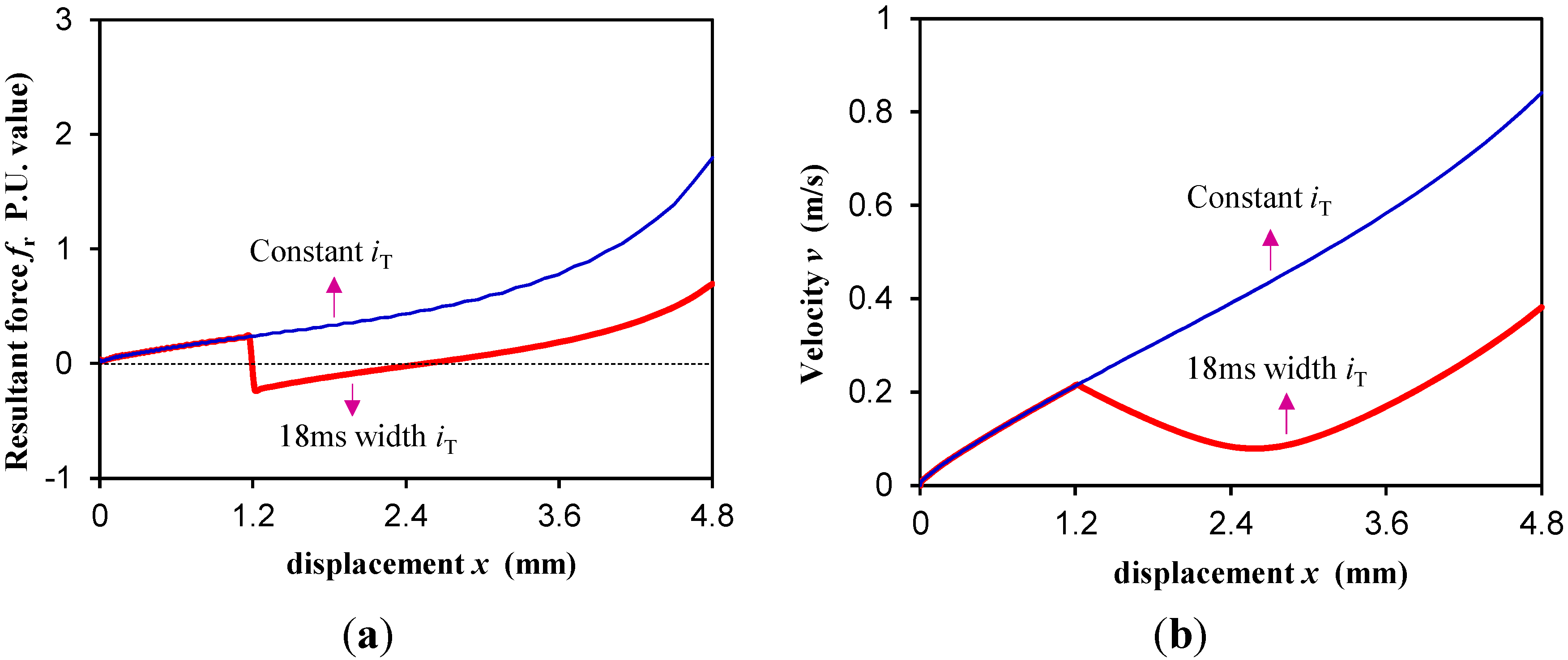
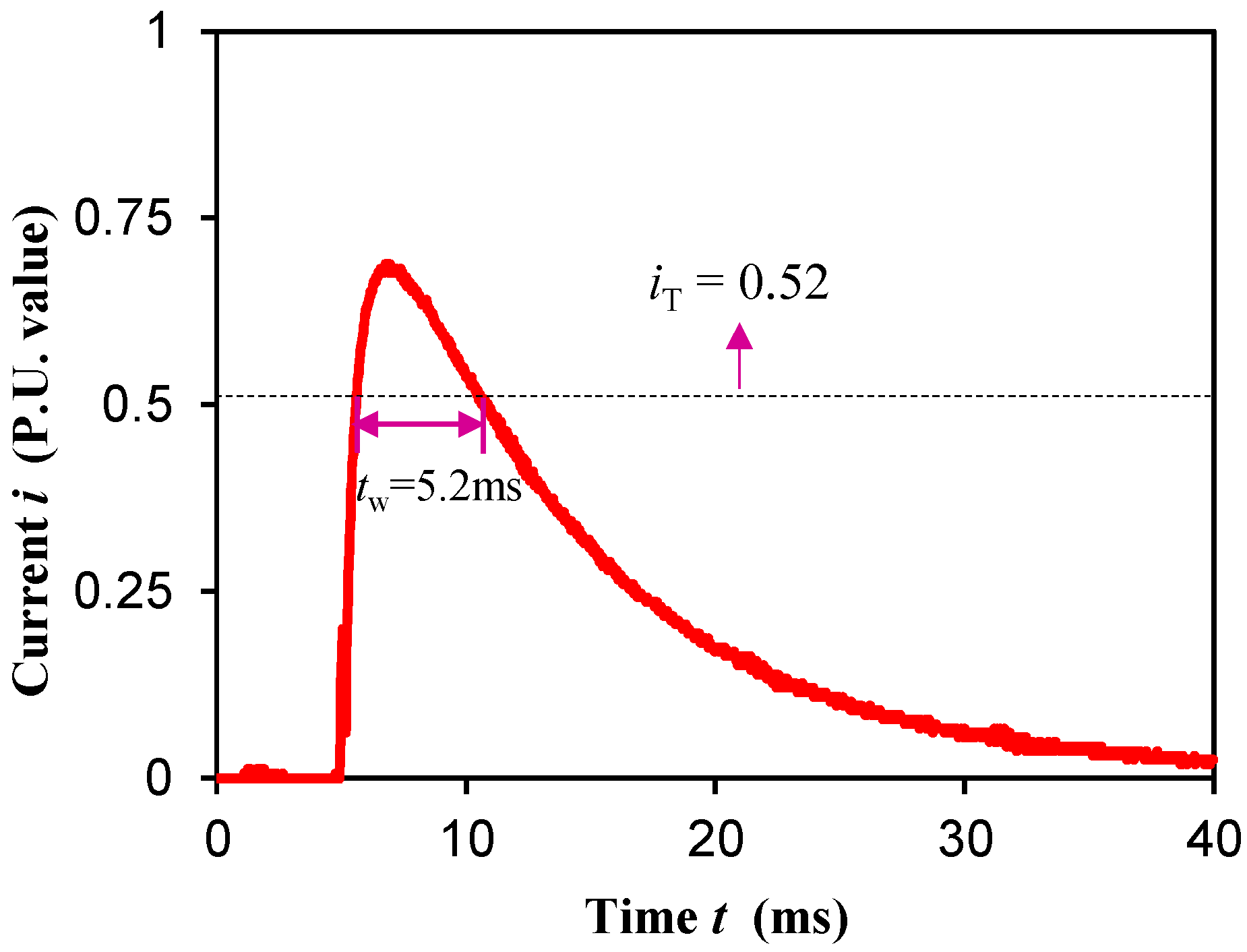
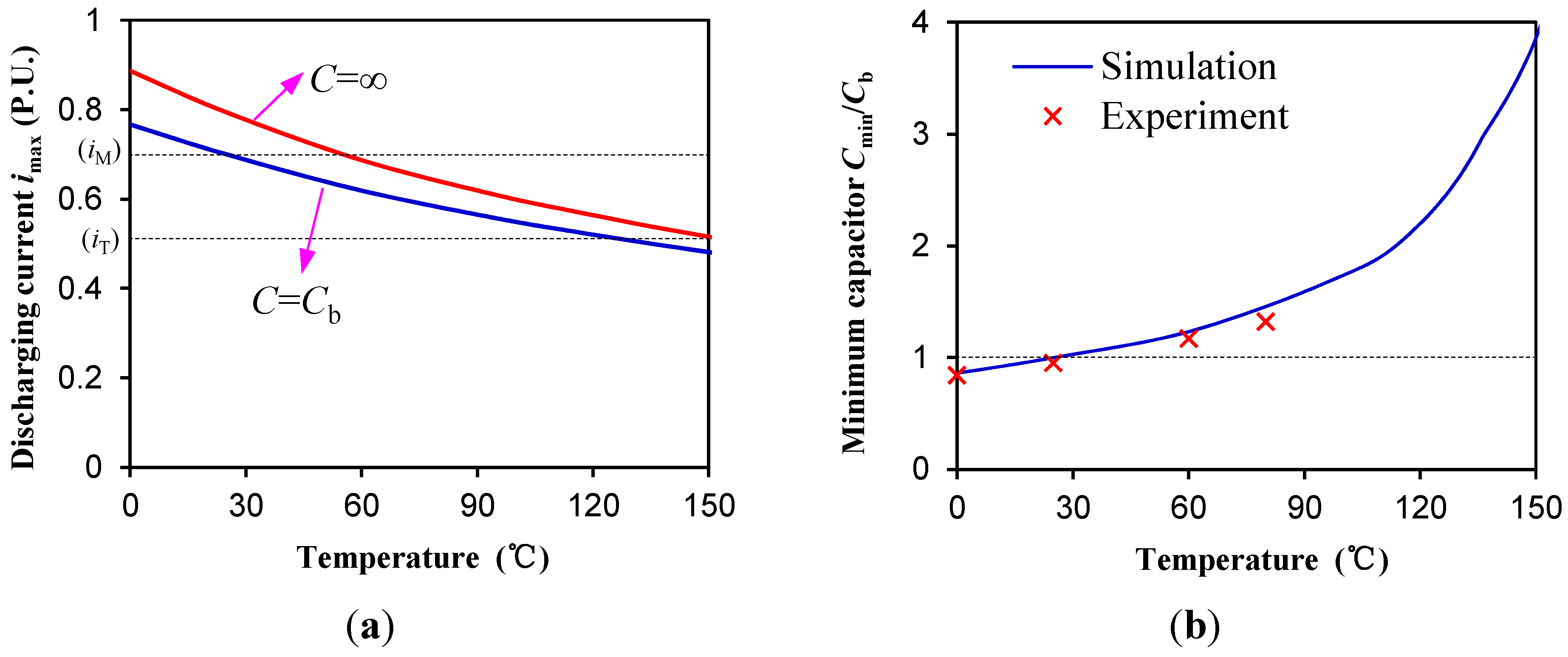
4.3. Minimum Driving Pulse Width

With the pulse threshold current accessed (in the calculations, the pulse width is given by the length of the displacement), the dynamics equations can be solved by the improved FEM, then the time pulse width, and finally the force and velocity curves versus displacement and different pulse widths, all can be obtained. The minimum pulse width tw is the pulse width of the threshold current which critically enables the switchover of the PMBECU between engagement and disengagement, i.e., the velocity of mover will be negative if the pulse width is less than tw. The resultant force and velocity curve of the prototype, which vary with displacement and pulse width, are shown in Figure 10.
Figure 9. Flowchart for solving the dynamics by improved FEM.
Energies 08 05598 g009
Figure 10. Dynamics characteristic under different pulse width. (a) Resultant horizontal force; (b) Velocity.
Energies 08 05598 g010
The smaller the width of the accessed pulse current, the more homogeneous the switchover process experienced by the mover will be. When the accelerating displacement is just longer than the decelerating displacement, it is the minimum current pulse width that accomplishes the switchover of the PMBECU between steady states, which is tw = 18 ms in this prototype.

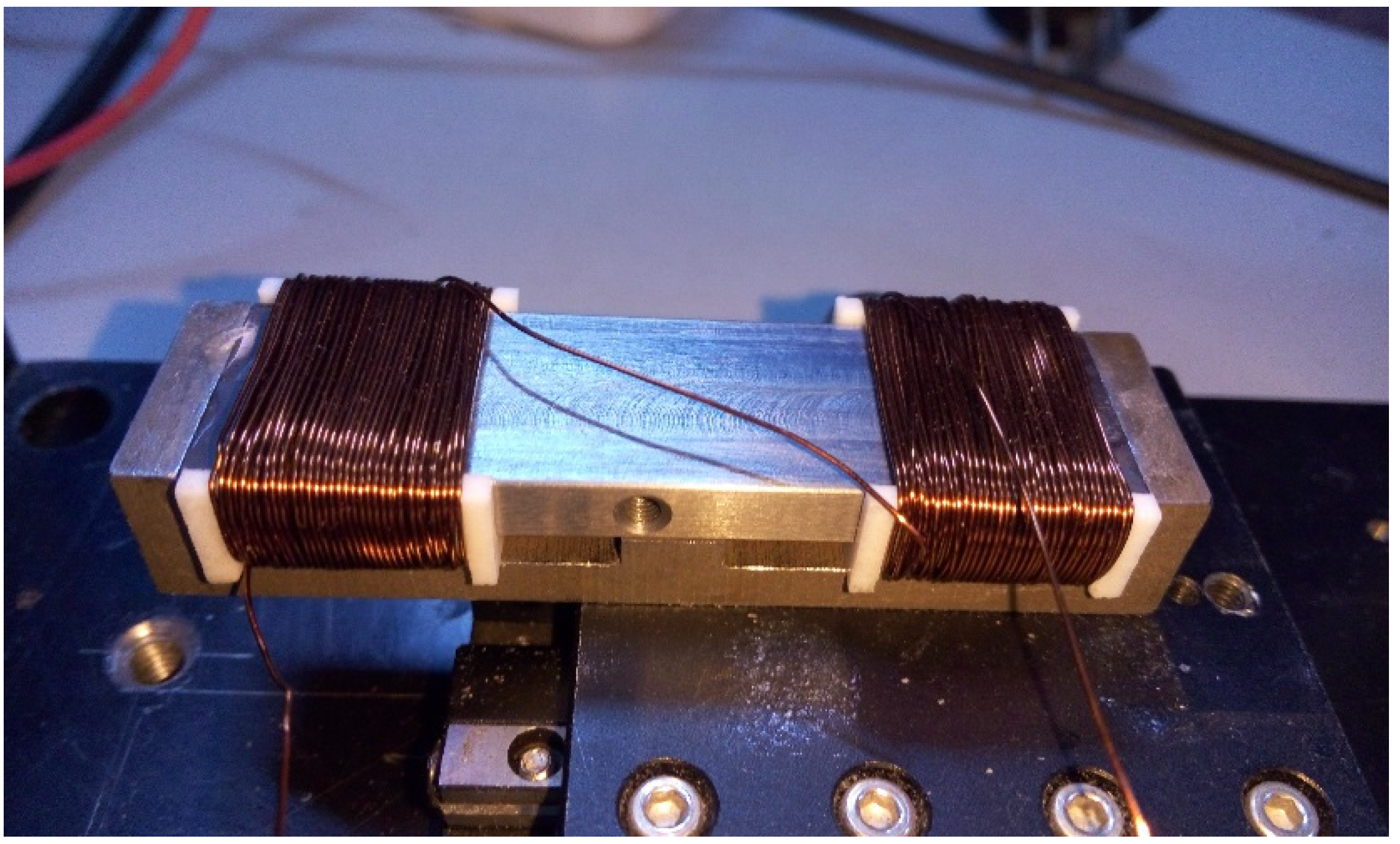
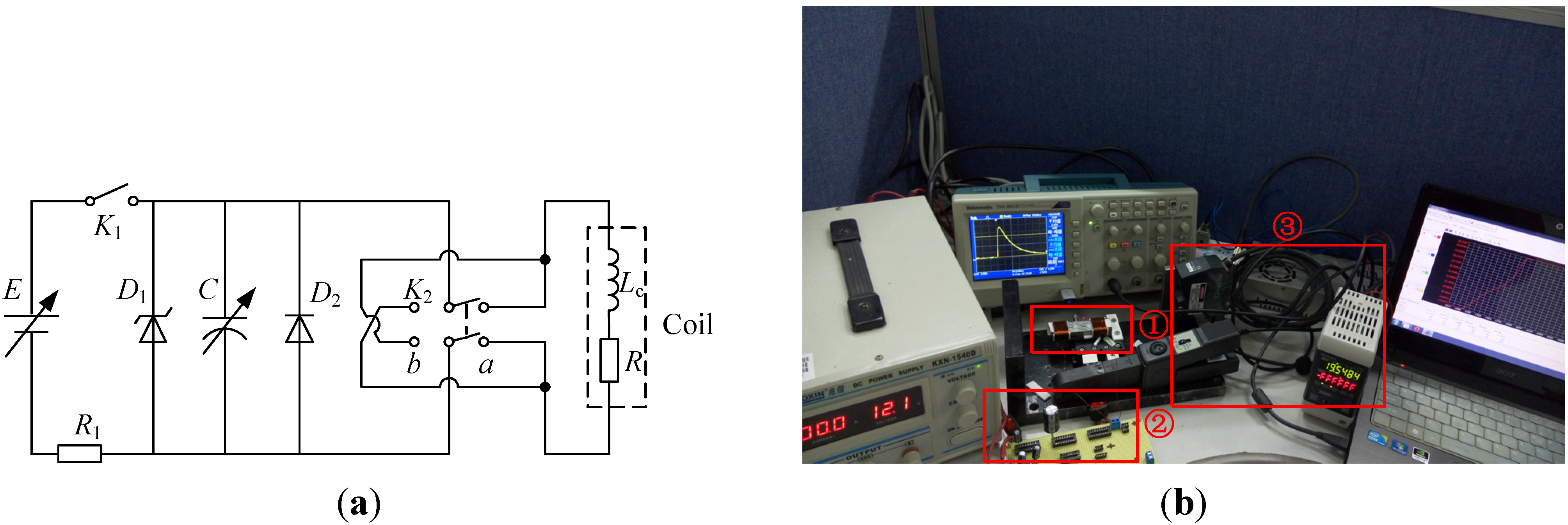
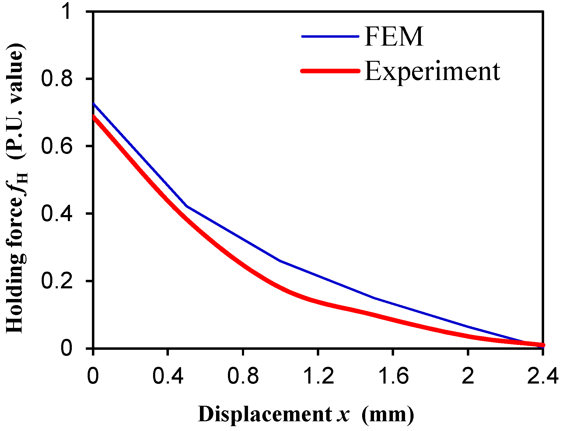
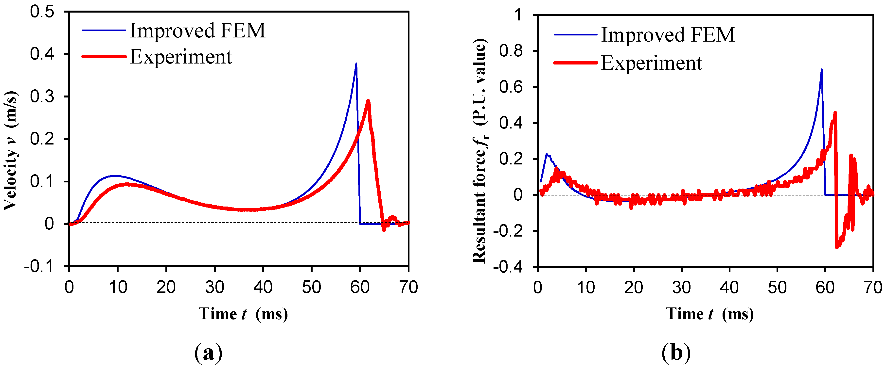
5. Experimental Validation

The experimental electric circuit as well as the experimental rig of the PMBECU are shown in Figure 11. First, the holding force at different positions was measured and compared to the FEM calculation results (there is an initial air gap δ1 = 0.1 mm and a contact air gap in the mid part of δ0 = 0.18 mm which had been accounted in the FEM model) as shown in Figure 12. The experimental results are a little smaller than the simulation results which is mainly attributed to the round corners of the PM, but it still shows an acceptable engineering accuracy.
Figure 11. (a) Experimental circuit; (b) Experimental rig, ① Prototype, ② Capacitor supply, ③ Laser displacement transducer.
Energies 08 05598 g011
Figure 12. Comparison of the holding force at different positions.
Energies 08 05598 g012
The pulse current applied to coil is approximately generated by a capacitor discharge lower power pulse supply. By changing the capacitance (i.e., changing pulse width), and tuning the charging voltage (keeping iM = 0.7), the practicable minimum pulse width can be obtained, which is tw = 5.2 ms in this prototype, and the corresponding discharge current curve is shown in Figure 13. Because the maximum discharge current is larger than the threshold current, and the continuous discharging current curve is superior to the rectangular pulse current, the minimum pulse width of the low power capacitor supply is much smaller.
In the dynamics experiments of the PMBECU (at an ambient temperature of 25 °C), the main electrical parameters are Cb = 8.6 mF, Rb = 1.15 Ω, and the displacement of the mover is recorded by a laser displacement transducer. In fact, the dynamics characteristics and minimum pulse width of the low power capacitor supply also can be obtained by the improved FEM, with the current value at each step solved by the electric circuit equation.
Figure 13. Discharge current curve of the low power supply which critically enables the switchover of the prototype.
Energies 08 05598 g013
The comparison between the improved FEM simulation and the experimental dynamics characteristics results are displayed in Figure 14, which shows a satisfactory agreement aside from the slight bounce of the mover, where the experimental velocity and dynamics force of the mover are derived from the differential and second order differential of the measured displacement curve. Thus, the improved FEM is an effective method for dynamics analysis of the PMBECU. What’s more, compared to the dynamics characteristics under constant current, the force on the mover is evener, the velocity of the mover is steadier, and the control is much simpler (the current decays automatically without switching off by position detection), and thus represents the optimal power supply scheme for the PMBECU.
Figure 14. Comparison of dynamics characteristics under low power pulse supply. (a) Velocity; (b) Resultant horizontal force.
Energies 08 05598 g014
In in-wheel drive applications, the device suffers from harsh working conditions—vibration, temperature variation and EMI, etc. The vibration and EMI influence the mechanical and control reliability of the PMBECU, respectively. However, from the aspect of electromagnetic analysis, the temperature variation mainly changes the electromagnetic characteristics of the PMBECU. When the temperature rises, the resistance approximately increases 0.43% per degree Celsius (compared to resistance Rb at 25 °C). The corresponding variation of the maximum discharge current imax is shown in Figure 15a. As shown, when temperature is less than 0 °C, imax is 10% larger than iM which is about to irreversibly demagnetize the PM, thus indication that a NdFeB PM is a better choice than a ferrite PM. When the temperature is higher than 150 °C, imax is less than the threshold current iT even though the capacitor is infinite, which will disable the PMBECU, and thus should be avoided. Figure 15b shows the variation of the minimum capacitor Cmin (compared to Cb at 25 °C) which critically enables the work of the PMBECU at different temperatures. Four measurement points of experiments prove the validity of the simulation. From Figure 15b, when the temperature rises, the work of the PMBECU requires a bigger capacitor because of the reduction of imax. Hence, the capacitor size should be determined by the maximum working temperature.
Figure 15. Electromagnetic characteristics variation with temperature. (a) Maximum discharge current; (b) Minimum capacitor enables the work of the PMBECU.
Energies 08 05598 g015

6. Conclusions

This paper proposes a permanent magnetic bi-stable electromagnetic clutch unit, which is introduced into in-wheel EV drives to turn the rigid connection between the hub and wheel into a more flexible form. The main structure parameters of the PMBECU are optimized by studying the leakage coefficient, holding force, and threshold current, which gives that the width of the PM, height from the PM to the base, and the travel length should better be around 2.5, 1.2, 2 times the thickness of the PM, respectively.
Based on the optimal structure parameters, a PMBECU prototype is fabricated. The basic electromagnetic characteristics indicate that the PMBECU is better controlled by pulse supply. Accordingly, an improved FEM is put forward to obtain the dynamics characteristics and minimum pulse width of the threshold current. The simulation results of both static force and dynamics characteristics are validated by experimental measurements on the prototype. Both the analysis and experimental results show that a low power capacitor supply is very suitable for the PMBECU, and the capacitor size should be determined under the maximum working conditions temperature. The analysis method and results lay a solid basis of the further design of whole clutch system.

Acknowledgments

This work was funded by National Natural Science Foundation of China (51377063).

Author Contributions

Wanli Cai conducted the simulations of FEM and experiments of the prototype and wrote the article. Xiaodong Hu did some experiments. Chenglin Gu proposed the basic idea and supervised the simulations and experiments.

Conflicts of Interest

The authors declare no conflict of interest.

References

  1. Chan, C.C.; Bouscayrol, A.; Chen, K.Y. Electric, hybrid, and fuel-cell vehicles: Architectures and modeling. IEEE Trans. Veh. Technol. 2010, 59, 589–598. [Google Scholar] [CrossRef]
  2. Chau, K.T.; Chan, C.C.; Liu, C.H. Overview of permanent-magnet brushless drives for electric and hybrid electric vehicles. IEEE Trans. Ind. Electron. 2008, 55, 2246–2257. [Google Scholar] [CrossRef] [Green Version]
  3. Lee, C.; Liu, C.H.; Chau, K.T. A magnetless axial-flux machine for range-extended electric vehicles. Energies 2014, 7, 1483–1499. [Google Scholar] [CrossRef] [Green Version]
  4. Lee, H.D.; Sul, S.K.; Cho, H.S.; Lee, J.M. Advanced gear-shifting and clutching strategy for a parallel-hybrid vehicle. IEEE Ind. Appl. Mag. 2000, 6, 26–32. [Google Scholar]
  5. Rahman, K.M.; Patel, N.R.; Ward, T.G.; Nagashima, J.M.; Caricchi, F.; Crescimbini, F. Application of direct-drive wheel motor for fuel cell electric and hybrid electric vehicle propulsion system. IEEE Trans. Ind. Appl. 2006, 42, 1185–1192. [Google Scholar] [CrossRef]
  6. Sakai, S.; Sado, H.; Hori, Y. Motion control in an electric vehicle with four independently driven in-wheel motors. IEEE Trans. Mech. 1999, 41, 9–16. [Google Scholar] [CrossRef]
  7. Ifedi, C.J.; Mecrow, B.C.; Brockway, S.T.M.; Boast, G.S.; Atkinson, G.J.; Perovic, D.K. Fault-Tolerant in-wheel motor topologies for high-performance electric vehicles. IEEE Trans. Ind. Appl. 2013, 49, 1269–1278. [Google Scholar] [CrossRef]
  8. Yang, Y.P.; Liu, J.J.; Wang, T.J.; Kuo, K.C.; Hsu, P.E. An electric gearshift with ultracapacitors for the power train of an electric vehicle with a directly driven wheel motor. IEEE Trans. Veh. Technol. 2007, 56, 2421–2431. [Google Scholar] [CrossRef]
  9. Usami, Y. Controller for Electric Vehicle. U.S. Patent 5896283, 20 April 1999. [Google Scholar]
  10. Kasten, R.E.; Newendorp, B.C.; Lemmen, N.F. Variable Current Limit Control for Vehicle Electric Drive System. U.S. Patent 6492785, 10 December 2002. [Google Scholar]
  11. Gu, C.L. Comprehensive review of electric vehicle PM wheel motors. MICROMOTORS (China) 2008, 41, 56–59. [Google Scholar]
  12. Xiong, P.; Gu, C.L. Optimal idling speed control of direct-drive electric vehicle launch in consideration of drive comfort. In Proceedings of the 17th International Conference on Electrical Machines and Systems (ICEMS), Hangzhou, China, 21–24 October 2014; pp. 225–228.
  13. Wu, D. Special Electromagnetic Clutch for a Novel Type of Transverse Flux Permanent Magnet Motor Direct Drive. Master’s Thesis, Huazhong University of Science and Technology, Wuhan, China, May 2011. [Google Scholar]
  14. Chen, L.; Xi, G.; Sun, J. Torque coordination control during mode transition for a series–parallel hybrid electric vehicle. IEEE Trans. Veh. Technol. 2012, 61, 2936–2949. [Google Scholar] [CrossRef]
  15. Camilleri, R.; Armstrong, P.; Ewin, N.; Richardson, R.; Howey, D.A.; McCulloch, M.D. The value of a clutch mechanism in electric vehicles. In Proceedings of the Conference of EVS27, Barcelona, Spain, 17–20 November 2013; pp. 1–11.
  16. Balau, A.E.; Caruntu, C.F.; Lazar, C. Simulation and control of an electro-hydraulic actuated clutch. Mech. Syst. Signal Process. 2011, 25, 1911–1922. [Google Scholar] [CrossRef]
  17. Gauthier, J.P.; Micheau, P.; Rioux, R. Vehicle Clutch Control Method. U.S. Patent 8,744,709, 3 June 2014. [Google Scholar]
  18. Ando, J.; Tsuda, T.; Ando, H.; Niikawa, Y.; Suzuki, K. Development of third-generation electronically controlled AWD coupling with new high-performance electromagnetic clutch. SAE Int. 2014, 7, 882–887. [Google Scholar] [CrossRef]
  19. Boules, N.M. Design analysis of electromagnetic particle clutch. In Proceedings of the Conference Record of the 1994 IEEE Industry Applications Society Annual Meeting, Denver, CO, USA, 2–6 October 1994; pp. 357–360.
  20. Duan, G.H. Clutch Structure Atlas; National Defence Industry Press: Beijing, China, 1985. [Google Scholar]
  21. Ohdachi, Y.; Kawase, Y.; Murakami, Y.; Inaguma, Y. Optimum design of dynamic response in automotive solenoid valve. IEEE Trans. Magn. 1991, 27, 5226–5228. [Google Scholar] [CrossRef]
  22. Kim, J.; Chang, J. A new electromagnetic linear actuator for quick latching. IEEE Trans. Magn. 2007, 43, 1849–1852. [Google Scholar] [CrossRef]
  23. Zhu, Z.Q.; Chen, X. Analysis of an E-core interior permanent magnet linear oscillating actuator. IEEE Trans. Magn. 2009, 45, 4384–4387. [Google Scholar] [CrossRef]
  24. Srairi, K.; Feliachi, M. Electromagnetic actuator behavior analysis using finite element and parametrization methods. IEEE Trans. Magn. 1995, 31, 3497–3499. [Google Scholar] [CrossRef]
  25. Kawase, Y.; Tatsuoka, S.; Yamaguchi, T.I. 3-D finite element analysis of operating characteristics of ac electromagnetic contactors. IEEE Trans. Magn. 1994, 30, 3244–3247. [Google Scholar] [CrossRef]
  26. Fang, S.H.; Lin, H.Y.; Ho, S.L. Transient co-Simulation of low voltage circuit breaker with permanent magnet actuator. IEEE Trans. Magn. 2009, 45, 1242–1245. [Google Scholar] [CrossRef]
  27. Woo, K.I.; Kwon, B.I. Characteristic analysis and modification of PM-type magnetic circuit breaker. IEEE Trans. Magn. 2004, 40, 691–694. [Google Scholar] [CrossRef]

