Article

A New Protection System for Islanding Detection in LV Distribution Systems

Department of Electrical and Information Engineering, University of Cassino and Southern Lazio, via Di Biasio 43, I-03043 Cassino, Italy
*
Author to whom correspondence should be addressed.
Energies 2015, 8(5), 3775-3793; https://doi.org/10.3390/en8053775
Submission received: 20 February 2015 / Revised: 23 April 2015 / Accepted: 27 April 2015 / Published: 30 April 2015

Abstract

:
The growth of penetration of Distributed Generators (DGs) is increasing the risk of unwanted islanded operation in Low Voltage (LV) distribution systems. In this scenario, the existing anti-islanding protection systems, installed at the DG premises and based on classical voltage and frequency relays, are no longer effective, especially in the cases of islands characterized by a close match between generation and load. In this paper, a new protection system for islanding detection in LV distribution systems is proposed. The classical voltage and frequency relays in the DG interface protections are enriched with an innovative Smart Islanding Detector, which adopts a new passive islanding detection method. The aim is to keep the advantages of the classical relays while overcoming the problem of their limited sensitivity in detecting balanced islands. In the paper, to define the requirements of the anti-islanding protection system, the events causing the islanded operation of the LV distribution systems are firstly identified and classified. Then, referring to proposed protection system, its architecture and operation are described and, eventually, its performance is analyzed and validated by experimental laboratory tests, carried out with a hardware-in-the-loop technique.

1. Introduction

In distribution systems, events caused by reconfiguration, maintenance or faults can leave all or part of a LV distribution network operating without the connection to the Medium Voltage (MV) distribution system and remaining energized as an autonomous entity by the Distributed Generators (DGs) connected to the isolated grid. Such an operation is referred to as islanding or loss-of-mains of the LV distribution network [1,2]. Unintentional islanding creates hazards for the utility personnel, who may intervene on parts of the LV network which should be isolated but are actually still energized by the DGs. Furthermore, such an unsupervised system operation may entail adverse power quality and impact on the equipment and customers within the islanded area. Eventually, the electrical equipment can be damaged by out-of-phase closure occurring when, after a fault, the unwanted island is reconnected to the utility network by automatic reclosing of MV breakers without any synchronizing action [3]. For all these reasons, the adoption of an adequate protection system able to detect any islanding condition and disconnect the DGs from the isolated network is essential to ensure the safe and secure operation of LV distribution systems.
Until a few years ago, the adoption of low-and high-voltage and low-and high-frequency relays, installed in the interface protection system at the DG premises, ensured the detection of islanding conditions. In fact, the low level of DG penetration in distribution networks caused a significant unbalance between generation and load during islanded operation; the resulting voltage and frequency perturbations were large enough to be detected by the low-and high-voltage and low-and high-frequency relays that tripped the DGs [4]. Over the last decade, the wide spread of DGs in LV distribution networks, especially of photovoltaic systems, has made it possible that, following the loss-of-mains, generation may balance load, maintaining the voltage and frequency within the admissible limits and preventing the intervention of the classical anti-islanding relays adopted by DGs [5].
A further issue is related to the false tripping of the DGs which is caused by classical anti-islanding relays. In fact, although the low-and high-voltage and low-and high-frequency relays do not permit the detection of “balanced islands”, their sensitivity is high enough to confuse voltage and frequency excursions due to islanded operation with the ones due to perturbations generated at the transmission or distribution level, such as faults or sudden load changes [5,6]. Nowadays, false islanding detections can cause a massive loss of generation through a domino effect in the distribution systems, with consequences on the stability of the transmission system [7]. Then, many national and international standards for the connection of DGs to the distribution networks have recently been revised and less restrictive thresholds for the classical DG relays have been adopted, with the adverse effect of increasing the inadequacy of the classical relays to detect balanced islanding operating conditions [1,8].
To avoid missing the detection of balanced islands as well as misclassifying other perturbations as loss-of-mains, a number of innovative solutions for the anti-islanding protection systems of the LV distribution networks have been proposed, including new relays based on communication systems [5,9] or classical relays equipped with additional new passive anti-islanding detection methods [5,10]. In the former solution, when an utility circuit breaker opens yielding an islanding condition, a communication-based relay detects the status of the breaker and sends signals to remotely disconnect the DGs. This solution could be very effective but may incur in prohibitive costs, especially for the LV distribution networks because it requires the realization of dedicated communication infrastructures between MV/LV substations and DGs. The second type of solution appears to be more adequate and economically-viable for LV distribution systems. The idea is to add new passive detection methods to the existing protection systems so as to correctly detect balanced islands without increasing DG false tripping in the case of other perturbations.
This paper proposes a new protection system for islanding detection in LV distribution systems which enriches the classical voltage and frequency relays installed at the DG premises with an innovative Smart Islanding Detector (SmartID), recently proposed from the authors to guarantee a reliable detection of the balanced islands when the classical relays fail. The SmartID adopts a new passive method based on a linear representation of the distribution system as seen from the SmartID installation point, which is named Thevenin-like model. Details about the method and its implementation in an actual device as well as about its validation in real grids can be found in [1,2]. The specific contribution of this paper is to analyze the features and the performance of the overall LV anti-islanding protection system, including both classical relays and the SmartID.
The paper is organized as follows: in Section 2 the events causing the islanded operation of the LV distribution system are identified and classified, so as to define the requirements of a reliable anti-islanding protection system. The architecture and operation of the proposed protection system is described in Section 3. Finally, experimental simulations results are reported in Section 4. The performance analysis is carried out by a hardware-in-the-loop test facility, whose core is the Real-Time Digital Simulator (RTDS) [11] that allows interfacing the real-time distribution system simulation with an actual SmartID device.

2. The Islanding Events in LV Distribution System

An islanding condition arises when a portion of the distribution system, including the DGs and loads, is inadvertently isolated from the upstream utility network and kept energized by the DGs [2]. The islanded operation of all/part of a LV distribution system can occur when there is the loss of the main supply delivered by the MV distribution system through the MV/LV substation. The islanded operation presents different features according to the cause that determines the loss of the main supply. In general, four cases can be recognized
  • loss of the MV supply in normal operation of the MV distribution system,
  • loss of the MV supply due to faults in the MV distribution system,
  • loss of the MV/LV substation in normal operation of the LV distribution system,
  • loss of the MV/LV substation due to faults in the LV distribution system.
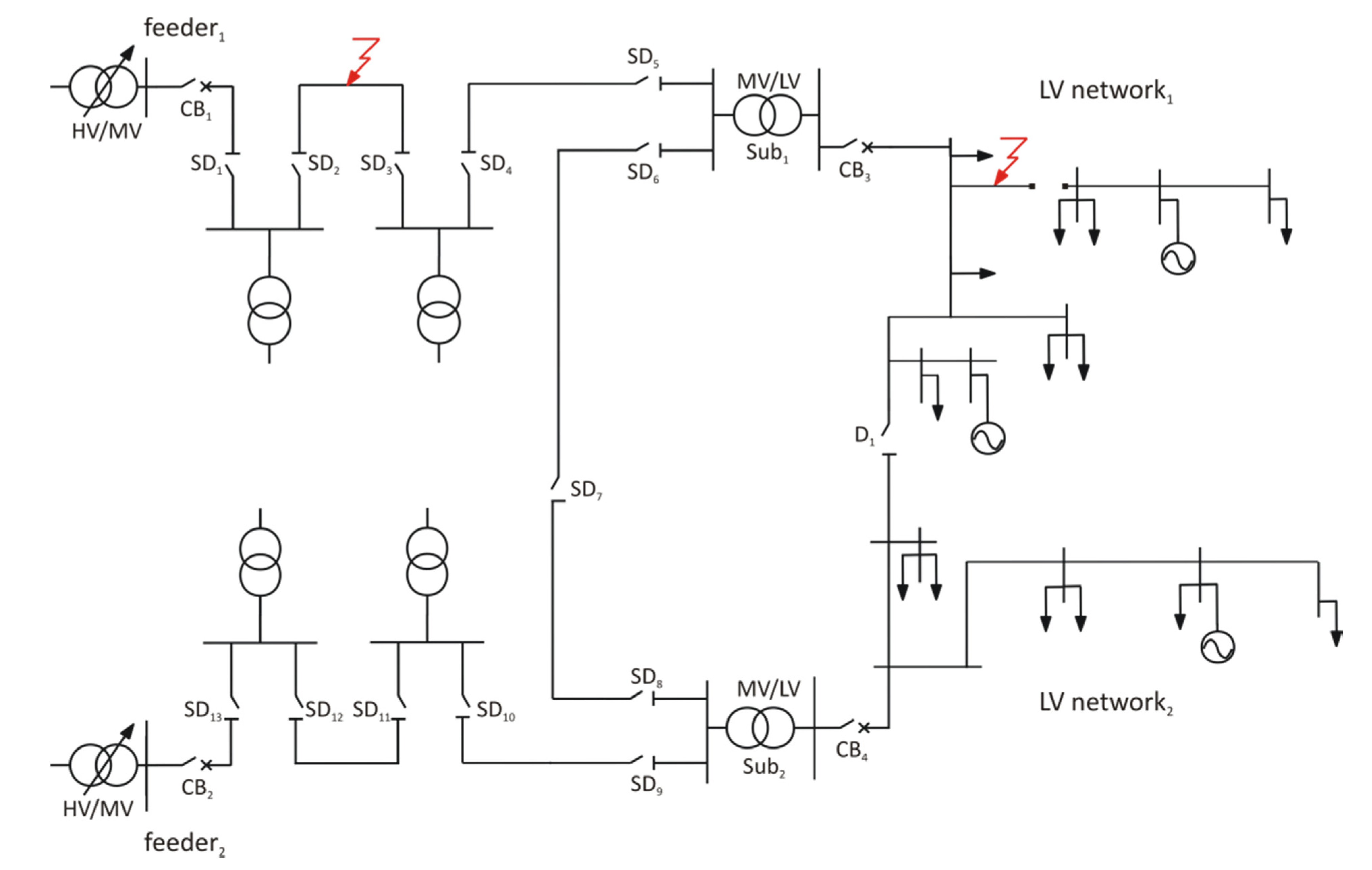
To analyze in details these cases, let the distribution system in Figure 1 be considered. The MV distribution system is composed of two feeders, indicated as feeder 1 and feeder 2 , supplied by two HV/MV transformers. Each MV feeder is protected by a circuit breaker at its head, named CB1 and CB2 respectively, and can be sectionalized by the switch disconnectors SD1, ..., SD13. In normal operation the two feeders are separated by SD7 which is normally opened but can change its status to guarantee a flexible reconfiguration of the MV distribution system. Two LV networks including DGs are evidenced and indicated as LV network 1 and LV network 2 : each one is supplied by a MV/LV substation, named Sub1 and Sub2 respectively, which are protected at their heads by two circuit breaker, CB3 and CB4; the two LV networks operate separately and the normally opened disconnector D1 can be used only for load transfer [12].
Figure 1. Simple distribution system with DGs.
Energies 08 03775 g001

2.1. Loss of the MV Supply in Normal Operation of the MV Distribution System

The loss of the MV supply can occur during the normal operation of the MV distribution system, as a consequence of switching operations for network reconfiguration or maintenance, or of false tripping in the MV networks. The MV network reconfiguration is used to reduce the distribution power losses and/or to relieve overloads; the maintenance is usually performed to improve the reliability of the MV distribution system; false tripping of the circuit breakers is caused by unexpected events [13,14,15]. Depending on the considered case, the loss of the MV supply can last for different time intervals. With reference to Figure 1 some examples are described in the following. A network reconfiguration can lead to supply Sub1 from feeder 2 by automatically closing SD7. In most cases this procedure does not cause the loss of the MV supply. However, if the network reconfiguration involves the simultaneous opening of the switch disconnectors in feeder 1 and feeder 2 , it will cause the loss of the MV supply for several seconds. The maintenance of a component of feeder 1 can require the intervention of the utility personnel, that manually opens CB1 to electrically isolate the component to be maintained; such an operation can last from minutes to hours. Finally, consequent to a false tripping of CB1, a loss of the MV supply can last for around few hundreds of milliseconds (typically 200 ms), after which feeder 1 is re-energised by the automatic reclosure of the circuit breaker.

2.2. Loss of the MV Supply due to Faults in the MV Distribution System

The loss of the MV supply can occur as a consequence of switching operations due to single/multiple phases faults in the MV distribution system; the duration of the faults is minimized by automatic reclosing procedures of the MV protection system [16]. In Figure 1, for example, subsequent to the fault along feeder 1 , the relays of the MV distribution system will detect the fault operating condition and will send an opening command to CB1. A first fast reclosure of CB1 is around 200 ms after the first CB1 opening. If the fault is cleared before the CB1 reclosure, the re-energization of the distribution system is successful; otherwise, CB1 is opened again together with SD1, ..., SD6. In this latter case, a second slow reclosure of CB1 is expected around 30 s after its first opening. After this reclosure, all the switch disconnectors are sequentially closed starting from SD1. If the fault is not cleared yet, the MV protection system can foresee further steps of the reclosing procedure, otherwise the fault has to be repaired.

2.3. Loss of the MV/LV Substation in Normal Operation of the LV Distribution System

In comparison with the MV distribution system, the LV distribution system does not present an high level of automation [17]. Thus, network reconfiguration, maintenance and false tripping require the intervention of the utility personnel, which causes lack of supply of LV system for long time intervals (minutes-hours). In Figure 1, for example, the maintenance of Sub1 requires to open both SD5, SD6 and CB3. If a network reconfiguration is expected, the LV network can be re-energized by opening CB4, changing the status of D1 and closing CB3 again. This manual procedure takes at least several minutes.

2.4. Loss of the MV/LV Substation due to Faults in the LV Distribution System

The loss of the MV/LV substation can occur as a consequence of single/multiple phases faults in the LV distribution system. For example, subsequent to the fault along the LV network 1 in Figure 1, the opening of CB3 yields the loss of Sub1. The reclosure of CB3 is not automatic and requires the manual intervention of the utility personnel that takes a long time (minutes-hours). If the fault is cleared, the first reclosure attempt is successful; otherwise the failure component must be repaired and the loss of the MV/LV substation lasts for even more time. Moreover, also in the case of a successful reclosure, part of the LV network could still remain unfed by Sub1, because the fault may cause a joint disconnection, evidenced in Figure 1 as a line interruption at the fault point in the LV network 1 .
From the previous analysis, some general considerations about the islanded operation of the LV distribution system can be derived, that allows to define the requirements of the anti-islanding protection system. They can be summarized as follows
-
the islanded operation of the whole LV distribution system can be caused by events occurring in the MV distribution system and can last for about 200 ms or for at least 30 s;
-
the islanded operation of all/part of the LV distribution system can be caused by events occurring in the LV distribution system and can lasts for long time intervals (minutes-hours).

3. The Proposed Anti-Islanding Protection System

3.1. Architecture of the Anti-Islanding Protection System

The proposed anti-islanding protection system is composed of classical frequency and voltage relays, SmartIDs and voltage detectors. Classical relays are installed at each DG site in the interface protection system. They have different thresholds depending on the type of DG involved. They trip very fast so as to avoid islanding conditions characterized by a significant power mismatch and to permit a successful fast reclosure in MV distribution system. Their detection time increases as the power imbalance decreases.
The innovative SmartIDs are integrated in the interface protection system of some or all the DGs; they are able to detect the islanding events when the variations of the electrical quantities are so small that are undetectable by the classical relays; they trip slowly but fast enough to guarantee a successful slow reclosure in MV and LV distribution systems.
Eventually, to increase the safety of the personnel a voltage detector can be installed at the head of the feeder in the MV/LV substation, so as to give a visual information about the absence or presence of the voltage on the LV network when the circuit breaker is opened.

3.1.1. Voltage and Frequency Relays

The voltage relay is designed to detect voltage variations subsequent to power imbalances in the islanded system. If the voltage at the DG interface exceeds or falls below a threshold value, the relay ceases to energize the power island by sending a trip signal to the circuit breaker of the DG after a time delay. The purpose of the time delay is to ride through short-term disturbances to avoid excessive false tripping. Commonly, the voltage relay assumes different tripping thresholds with different tripping delays according to the standards adopted by different jurisdictions. Table 1 shows the minimum requirements for the voltage protection relays for the IEEE and the IEC standards together with the limits adopted by the Italian standard [18,19,20].
Table 1. Voltage requirements for LV distribution system.
IEEE 1574IEC 61727CEI 0-21
DG sizeV (%) *tc ** (s)V (%) *tc ** (s)V (%) *tc ** (s)
30 kW 1200.16 1350.05 110 3.00
110 < V < 1201.00110 < V < 1352.00 1150.20
50 V < 882.0050   V < 852.00<850.40
<500.16<500.10<400.20
> 30 kW 120 0.16
110 < V < 120 1.00
50 V < 88 2.00
<50 0.16
* % of the nominal distribution system voltage; ** the clearing time tc is the time between the occurrence of the island and the opening of the DG circuit breaker.
The frequency relay is designed to detect frequency variations subsequent to power imbalances in the islanded system. It incorporates two types of detector, namely the low- and high-frequency and the rate-of-change-of-frequency (ROCOF) relays, which operate in a combined manner. When the frequency in the island is lower/higher than a threshold value, a trip signal is immediately sent to the circuit breaker of the DG. The ROCOF detector is used to accelerate the detection and to solve the problem of the fast reclosure in MV distribution networks, as shown in the Appendix. In addition, a minimum voltage block function is implemented in such relay to block the trip signal during the generator start-up or the short-circuits. Again, the frequency relay presents different tripping thresholds with different trip delays, which vary according to the standards adopted by different jurisdictions. Table 2 shows the minimum requirements for the frequency protection relays for the IEEE and the IEC standards together with the limits adopted by the Italian standard [18,19,20].
Table 2. Frequency requirements for LV distribution system.
IEEE 1574IEC 61727CEI 0-21
DG sizef (Hz)tc (s)f (Hz)tc (s)DG typef (Hz)tc (s)
30 kW>60.50.16>51.00.20Rotating>50.50.10
<59.30.16<49.00.20<49.50.10
> 30 kW>60.50.16Static>51.50.10 or 4.00 **
<(59.8–57.0) *(0.16–300) *<47.50.10 or 4.00 **
<57.00.16
* adjustable; ** the clearing time tc is equal to 0.10 s or 4.00 s according to whether any integrative remote control protection system is absent or present.

3.1.2. SmartID

The SmartID is able to detect the islanding events even in the case in which the variations of the electrical quantities are so small that are undetectable by the classical relays. The passive method adopted by the SmartID is described by the block scheme in Figure 2. On the basis of local voltage v ( t ) and current i ( t ) measurements, the corresponding phasors V ¯ and I ¯ at the fundamental frequency are evaluated to estimate the parameters a ¯ and b ¯ of a linear Thevenin-like model, representing the LV distribution system as seen from the DG. The dimensions of the parameters a ¯ and b ¯ are, respectively, a voltage and an impedance. The detection method is based on the variations of the absolute values a   and b assumed by a ¯ and b ¯ in grid-connected and islanded operation. Comparing a   and b with their respective thresholds r e f a and r e f b , if:
a r e f a  and  b r e f b
an output signal O S is generated which is representative of the grid-connected operation; on the other hand, if:
a < r e f a  and  b > r e f b
a different output signal O S is generated which is representative of the islanded operation. Details about the islanding detection method and its implementation in the SmartID prototype can be found in [10,21].
Table 3 shows the thresholds refa and refb adopted by the SmartIDs, which are set according to the procedure described in [22]. Two interdiction zones are determined which clearly separate the values assumed by the estimated parameters a and b, respectively, in grid-connected and islanded operation; then, refa and refb can be fixed inside such interdiction zones. Indeed, for a given operating condition (grid-connected or islanded), the values of a and b are anyway subject to variations, due to changes of the loads and DG power injections in the distribution system and/or events occurring at higher voltage levels. Such variations of a and b are tracked by the estimator block in Figure 2; if the estimated values of a and b fall inside the interdiction zones and pass across the thresholds, a false detection occurs. To overcome this problem and improve SmartID stability with respect such variations of a and b, in this paper a hysteresis is introduced by using two different values for each threshold, refa and refb, in dependence of the type of the transition (from grid connected to islanded operation and viceversa) according to Table 3. To explain how the two threshold values are set and the benefits introduced by the hysteresis, let parameter a be considered for example. In grid-connected operation a generally lies above the interdiction zone, whereas in islanded operation it lies below the interdiction zone. The transition from grid-connected to islanded operation must be detected when the estimated value of a goes below the interdiction zone: by fixing refa in the lowest part of the interdiction zone, the SmartID correctly detects actual transitions from grid-connected to islanded operation and does not erroneously detect the variations that may cause the value of a falling in the interdiction zone. On the contrary, the inverse transition from islanded to grid-connected operation is detected when the estimated value of a goes above the interdiction zone: by fixing refa in the highest part of the interdiction zone, the SmartID correctly detects actual transitions from islanded to grid-connected operation while avoiding misdetections. Similar considerations can be made for the other parameter b.
Table 3. SmartID thresholds.
Transition operation r e f a r e f b
(V)(Ω)
grid connected→ islanded1202.0
islanded→ grid connected2001.0
Figure 2. Block diagram of the SmartID.
Energies 08 03775 g002
The clearing time is not fixed but depends on many factors related to the detection method adopted by the SmartID. In general, the clearing time is of the order of seconds and has not to exceed 30 s to guarantee the successful MV slow reclosure.

3.2. Operation of the Protection System

The operation of the protection system is considered with reference to the events summarized at the end of Section 2.

3.2.1. Islanded Operation of the Whole LV Distribution System due to MV Network Events

As described in Section 2, subsequent to the loss of the MV supply due to MV network events, the whole LV distribution system can operate in islanding for either about 200 ms or at least 30 s. In most cases the imbalance between DGs and loads causes variations of frequency and voltage in the islanded system, such that the classical relays provide to disconnect all the DGs within 200 ms and the islanded operation ends before any possible recovery of the main supply. On the contrary, if the DGs match loads, the classical relays do not detect islanding within 200 ms and the fast reclosure occurs while the DGs is still connected to the distribution system. Then, two cases can occur. If the MV fault is extinguished, the reclosure is successful but can be out-of-phase. In the Appendix, it is shown how adequate thresholds adopted by classical relays avoid in this case a reclosure with more than 20° of voltage phase displacement [5]. If the MV fault is not extinguished, the reclosure fails and the islanded operation of the whole LV distribution system continues; the adoption of classical relays and SmartIDs assures that DGs are tripped before the slow reclosure of the circuit breaker, occurring 30 s after the failure of the first reclosure.

3.2.2. Islanded Operation of All/Part of the LV Distribution System due to LV Network Events

As described in Section 2, subsequent to the loss of the MV/LV substation due to LV network events, an islanding operation of all/part of the LV distribution system can last for long time (minutes-hours). The adoption of classical relays together with the SmartIDs guarantees the detection of balanced and unbalanced islands and the tripping of DGs within 30 s.

4. Numerical Simulations

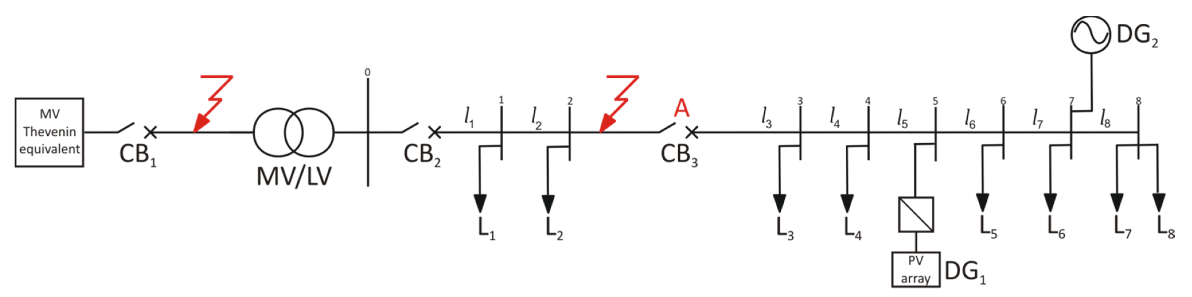
The experimental studies have been performed with reference to the test distribution system in Figure 3. It is composed of a 20   kV 50   Hz distribution system, represented by a Thevenin equivalent and the circuit breaker CB1, which supplies through a 20 / 0.4   kV - 0.25   MVA transformer a 0.4   kV three-phases feeder protected by the utility breaker CB2. The electric parameters of the lines l 1 ,..., l 7 are reported in Table 4. The active and reactive powers absorbed by the loads L 1 , , L 8 supplied by the LV feeder are shown in Table 5; loads L 4 , L 7 are subject to random variations within the range reported in Table 5. The LV distribution system includes two 0.25   MVA DGs, named DG1 and DG2. DG1 is a photovoltaic system coupled with the grid by a power converter; the active power is controlled and varies following the random irradiation, while the reactive power is controlled with a power factor equal to 0.9. DG2 is a small hydro-turbine moving a three-phase synchronous generator, which is equipped with active and reactive power control systems, whose set-points are fixed so as to create and sustain balanced islands, as described in the following. Both the DG interfaces include the low-and high-voltage and low-and high-frequency relays, whose thresholds are fixed according to the CEI standard as reported, respectively, in Table 1 and Table 2. The SmartID device is connected at the terminals of either DG1 or DG2 and its thresholds are reported in Table 3.
Figure 3. Test distribution system.
Energies 08 03775 g003
Table 4. Electric parameters of the lines.
l 1 l 2 l 3 l 4 l 5 l 6 l 7
RXRXRXRXRXRXRX
(Ω)(Ω)(Ω)(Ω)(Ω)(Ω)(Ω)(Ω)(Ω)(Ω)(Ω)(Ω)(Ω)(Ω)
0.0670.0160.0380.0090.0730.0170.0510.0090.0610.0090.0330.0050.0260.004
Table 5. Active and reactive powers absorbed by the loads.
Powers L 1 L 2 L 3 L 4 L 5 L 6 L 7 L 8
P (kW)1.50.5821.00.0 ÷ 1.54.441.50.0 ÷ 1.63.0
Q (kVAr)0.680.269.450.0 ÷ 0.682.00.680.0 ÷ 0.721.35
The analysis is carried out by a hardware-in-the-loop test facility. The core of the set-up is the RTDS [11] equipped with RSCAD/EMTDC, which is used to simulate in real-time the distribution network, the DGs and the classical interface protections. Conversely, the SmartID is an actual device, interfaced with the RTDS by D/A converters.
The aim of the case study is to compare the proposed anti-islanding protection system with the classical one. Two different analysis are carried out. The first one aims at comparing the performance of the two protection systems in detecting islands characterized by the exact balance between generation and load. The second one is a sensitivity analysis that aims at evaluating the impact of different imbalances of the active power Δ P and of the reactive power Δ Q on the performance of the two protection systems. In both the analysis two events are considered (see Section 2)
  • Event 1: islanded operation of the whole LV distribution system caused by a single-phase fault in the MV distribution system with the failure of the fast reclosure;
  • Event 2: islanded operation of part of the LV distribution system caused by a three-phase fault in the LV distribution system yielding joint-disconnection.
To take into account the stochastic nature of loads and irradiation, the analysis are carried out by adopting a statistical approach. Repeated simulations of the same distribution system changing from grid-connected to islanded operation are performed by imposing random variations of the two variable loads and the irradiation of the photovoltaic system.
The transition from grid-connected to islanded operation is simulated by opening a circuit breaker in the distribution system when the power imbalance in the island is equal to the desired value, achievable by acting on the DG2 control system.
In the case of Event 1, the simulation starts with both the DGs in connection with the MV supplying system; acting on the DG2 control system, the powers flowing through CB2 are reduced to the desired power imbalances Δ P and Δ Q . Then, a single-phase fault occurs at the MV busbar, as shown in Figure 3. After 150 ms, CB1 is opened thus simulating the action of the MV protection system against fault; after further 200 ms, the fast reclosure of CB1 takes place but fails and CB1 is opened again after 150 ms. In this way, the whole LV distribution system operates in island while the single-phase fault in the MV network is not extinguished.
In the case of Event 2, the joint is located in the point A of the line l 3 in Figure 3 and its disconnection is simulated by the opening of the breaker CB3. The simulation starts with both the DGs in connection with the MV/LV substation; acting on the DG2 control system, the powers flowing through CB3 are reduced to the desired power imbalances Δ P and Δ Q . Then, a three-phase fault occurs along the line l 3 , as shown in Figure 3. After 50 ms, CB3 is opened thus simulating the joint disconnection and a part of the LV distribution system operates in island.
The performance of the anti-islanding protection systems is measured on the basis of the successful detections and the related detection times (the detection time represents the time interval elapsing between the occurrence of the island and the change of the relay output) for the voltage and frequency relays and the SmartID. The use of detection times rather than the clearing times allows the use of the same simulation to compare the performance of the two protection systems. The detection times are expressed in terms of Gaussian statistical distributions. For the sake of comparison, some performance indices are derived from the distributions, namely the percentage of missed detections p m d , the mean value μ s d and the standard deviation σ s d of the detection times in the cases of successful detections.

4.1. Performance Analysis in Balanced Islands

The performances of the two protection systems in detecting islands characterized by Δ P = 0 and Δ Q = 0 are compared. Four cases are analyzed, combining the two events causing the islanded operation and the SmartID installation points:
(a)
Case A: Event 1 with the SmartID connected to DG1;
(b)
Case B: Event 1 with the SmartID connected to DG2;
(c)
Case C: Event 2 with the SmartID connected to DG1;
(d)
Case D: Event 2 with the SmartID connected to DG2.
For each case twenty simulations have been performed.

4.1.1. Case A

Table 6 reports the detection times for the classical voltage and frequency relays installed at both the DG1 and DG2 interfaces, indicated respectively as V / f D G 1 and V / f D G 2 , and for the SmartID connected to the DG1 terminals, indicated as S I D D G 1 for each simulation. Detection times overcoming 120 s are not reported and considered as a missed detection. It is evident from Table 6 that V / f D G 1 and V / f D G 2 often fail detection due to the balanced island and, in general, V / f D G 1 takes more time to intervene with respect to V / f D G 2 because its thresholds setting is less restrictive. On the contrary, the SmartID always identifies islanding with limited detection times. It is worth to notice that in trial 14 V / f D G 1 and V / f D G 2 are faster than S I D D G 1 ; this is due to the random variations of PV generation and loads which can sometimes cause large voltage and frequency excursions and the subsequent fast intervention of the classical relays.
Table 6. Detection times in the Case A.
TrialDetection time (s)
V / f D G 1 S I D D G 1 V / f D G 2
1-6.9687.84
26.511.996.30
3-4.73100.70
472.881.8750.98
5-4.62-
67.132.986.92
772.851.7550.63
87.616.337.40
9-3.44-
10-3.77-
11-5.7153.22
1277.831.7854.64
13-3.0655.37
146.447.276.24
157.343.357.56
1672.852.5650.59
17-3.3087.98
1872.853.3550.59
19-6.01-
20-5.5848.64
Table 7 reports the performance indices derived from Table 6. They are evaluated not only for each relay but also for both the overall classical and proposed protection systems. Comparing the single relays, S I D D G 1 successfully detects the condition of islanding while V / f D G 2 fails for the 20% of the simulations and V / f D G 1 fails for the 50% of the simulations. Referring to the successful detections, the fastest relays is S I D D G 1 which averagely takes 4.02 s whereas V / f D G 1 and V / f D G 2 take more than 30 s, which is the requirement of a reliable anti-islanding protection system for LV networks. Also the standard deviation of S I D D G 1 is very limited, differently from the other ones. Comparing the classical to the proposed protection systems, the latter one presents a more reliable and effective performance, because it always detects islanded operation and it averagely takes 3.97 s rather than 45.34 s to detect island. It is worth to notice that average detection time of the overall proposed protection system is smaller than the one of the single SmartID, because, as previously explained, there is a case in which the classical relays are faster than the SmartID.
Table 7. Comparison between the classical and the proposed protection systems in the Case A.
Performance indicesSingle relayClassical protection systemProposed protection system
V / f D G 1 S I D D G 1 V / f D G 2
p m d (%)5002020 0
μ s d (s)40.434.0245.3545.343.97
σ s d (s)35.261.7731.0531.071.68

4.1.2. Case B

Moving the SmartID from DG1 to DG2, the results in Table 8 confirm the reliability and the effectiveness of the proposed protection system in detecting island when generation and load closely match. The results related to S I D D G 2 are even better than the ones of S I D D G 1 in the previous case. In both Table 7 and Table 8, the values of p m d and μ s d are always worse for V / f D G 1 with respect to V / f D G 2 , due to the less restrictive threshold setting of V / f D G 1 . For this reason, in the following Section 4.2 the sensitivity analysis is performed assuming the SmartID installed at the DG1 terminals to empower its interface protection system.
Table 8. Comparison between the classical and the proposed protection systems in the Case B.
Performance indicesSingle relayClassical protection systemProposed protection system
V / f D G 1 V / f D G 2 S I D D G 2
p m d (%)30150150
μ s d (s)70.1751.312.9751.312.97
σ s d (s)10.5819.721.4719.721.47

4.1.3. Case C

Table 9 reports the performance indices for the single relay V / f D G 1 , V / f D G 2 and S I D D G 1 as well as for both the overall classical and proposed protection systems. Comparing the single relays, V / f D G 1 fails for the 20% of the simulations, S I D D G 1 always detects the condition of islanding and V / f D G 2 fails for 5% of the simulations. Referring to the successful detections, the fastest relay is S I D D G 1 which on average takes 7.85 s and also presents a limited standard deviation with respect to the other relays. Comparing the classical to the proposed protection systems, the latter one presents a more reliable and effective performance.
Table 9. Comparison between the classical and the proposed protection systems in the Case C.
Performance indicesSingle relayClassical protection systemProposed protection system
V / f D G 1 S I D D G 1 V / f D G 2
p m d (%)200550
μ s d (s)59.027.8538.3136.847.67
σ s d (s)24.062.5221.5718.132.46

4.1.4. Case D

Moving the SmartID from DG1 to DG2, the results in Table 10 confirm that the proposed protection system, thanks to presence of the SmartID, is always able to identify balanced islands in a limited interval of time. Comparing Table 9 and Table 10, it is evident that, also in this case, the SmartID located at the DG2 terminals averagely takes smaller time to detect island than the one located at the DG1 terminals.
Table 10. Comparison between the classical and the proposed protection systems in the Case D.
Performance indicesSingle relayClassical protection systemProposed protection system
V / f D G 1 V / f D G 2 S I D D G 2
p m d (%)55100100
μ s d (s)35.1334.786.0534.655.65
σ s d (s)32.1919.042.5219.221.35

4.2. Sensitivity Analysis with Respect to Power Imbalances

The impact of different Δ P and Δ Q on the performance of the two protection systems is analyzed. Four cases are considered, combining the two events causing the islanded operation and different types and amplitudes of the power imbalance:
(a)
Case A: Event 1 with Δ P = ( 10 , 5 , + 5 , + 10 ) % and Δ Q = 0 ;
(b)
Case B: Event 1 with Δ P = 0 and Δ Q = ( 5 , + 5 ) % ;
(c)
Case C: Event 2 with Δ P = ( 10 , 5 , + 5 , + 10 ) % and Δ Q = 0 ;
(d)
Case D: Event 2 with Δ P = 0 and Δ Q = ( 5 , + 5 ) % .
In all the cases the SmartID has been installed at the DG1 premises whose voltage and frequency relays present less restrictive thresholds. As in the previous analysis, twenty simulations are carried out for each considered case.

4.2.1. Case A

The results of a sensitivity analysis of the performance indices with respect to an active power imbalance Δ P ranging from −10% to +10% are reported in Table 11. Also in the case of significant power imbalances, V / f D G 1 fails by either missing detection or presenting an unacceptable detection time. On the contrary, V / f D G 2 and S I D D G 1 successfully detect the unwanted conditions with adequate detection times. Comparing the performance indices of the classical and of the proposed protection systems, the correct operation within 30 s of both the solutions is evident, although the proposed system always presents smaller μ s d and σ s d . This result could be misleading: the successful intervention of the classical protection system is due to the presence of V / f D G 2 characterized by strict thresholds, that are going out of use. It is worth noticing that further increases of Δ P are not analyzed because the larger the frequency and voltage excursions are, the faster the intervention of the classical relays.
Table 11. Comparison between the classical and the proposed protection systems in the Case A.
Performance indicesSingle relayClassical protection systemProposed protection system
V / f D G 1 S I D D G 1 V / f D G 2
p m d (%) Δ P = + 5 %   Δ Q = 0 300000
Δ P = + 10 %   Δ Q = 0 600000
Δ P = 5 %   Δ Q = 0 300000
Δ P = 10 %   Δ Q = 0 250000
μ s d (s) Δ P = + 5 %   Δ Q = 0 63.386.0511.5411.535.98
Δ P = + 10 %   Δ Q = 0 26.147.973.633.552.64
Δ P = 5 %   Δ Q = 0 31.137.0811.1411.125.75
Δ P = 10 %   Δ Q = 0 73.697.441.821.761.62
σ s d (s) Δ P = + 5 %   Δ Q = 0 18.052.193.383.402.06
Δ P = + 10 %   Δ Q = 0 23.773.003.863.752.59
Δ P = 5 %   Δ Q = 0 31.653.364.914.942.05
Δ P = 10 %   Δ Q = 0 31.792.062.352.301.97

4.2.2. Case B

In Table 12, the results of a sensitivity analysis of the performance indices with respect to a reactive power imbalance Δ Q ranging from −5% to +5% are reported. Concerning V / f D G 1 , it presents an opposite behavior with respect to the sign of Δ Q : for a positive variation it always detects islanded operation whereas for a negative one it always misses detection. This is due to the asymmetrical setting of the voltage thresholds reported in Table 2. Concerning V / f D G 2 , it always detects the unwanted conditions in a small time thanks to the frequency relay with strict threshold settings. Concerning S I D D G 1   , it always identifies islands with a performance similar to the one observed for imbalances of Δ P ; it can be stated that the SmartID is quite insensitive to the type, the sign and the amplitude of the power imbalance. Concerning the classical and the proposed protection systems, considerations similar to the ones of the previous case can be made.
Table 12. Comparison between the classical and the proposed protection systems in the Case B.
Performance indicesSingle relayClassical protection systemProposed protection system
V / f D G 1 S I D D G 1 V / f D G 2
p m d (%) Δ P = 0 %   Δ Q = + 5 % 00000
Δ P = 0 %   Δ Q = 5 % 1000000
μ s d (s) Δ P = 0 %   Δ Q = + 5 % 23.627.871.061.040.95
Δ P = 0 %   Δ Q = 5 % -7.402.522.432.21
σ s d (s) Δ P = 0 %   Δ Q = + 5 % 10.272.831.551.511.13
Δ P = 0 %   Δ Q = 5 % -1.673.723.643.22

4.2.3. Case C

Table 13 reports the performance indices of the single relays and of the two protection systems which are obtained by varying the active power imbalance Δ P from −10% to +10%. Even if significant power imbalances arise, V / f D G 1 misses detection several times. Even when V / f D G 1 detects island, it takes minutes and the order of magnitude of its μ s d and σ s d   are too large to guarantee an adequate level of power quality so as to avoid electric equipment damages. On the contrary, V / f D G 2 and S I D D G 1 and both the classical and the proposed protection systems successfully detect the unwanted conditions with adequate detection times. As already explained, the successful intervention of the classical protection system is due to the presence of V / f D G 2 characterized by strict thresholds, that are going out of use.
Table 13. Comparison between the classical and the proposed protection systems in the Case C.
Performance indicesSingle relayClassical protection systemProposed protection system
V / f D G 1 S I D D G 1 V / f D G 2
p m d (%) Δ P = + 5 %   Δ Q = 0 150000
Δ P = + 10 %   Δ Q = 0 350000
Δ P = 5 %   Δ Q = 0 150000
Δ P = 10 %   Δ Q = 0 300000
μ s d (s) Δ P = + 5 %   Δ Q = 0 67.807.3517.1317.106.90
Δ P = + 10 %   Δ Q = 0 53.546.950.770.770.77
Δ P = 5 %   Δ Q = 0 46.268.4410.2010.205.42
Δ P = 10 %   Δ Q = 0 35.677.960.660.660.66
σ s d (s) Δ P = + 5 %   Δ Q = 0 19.412.065.885.902.29
Δ P = + 10 %   Δ Q = 0 28.351.540.010.010.01
Δ P = 5 %   Δ Q = 0 33.102.248.378.373.82
Δ P = 10 %   Δ Q = 0 31.141.680.070.070.07

4.2.4. Case D

Table 14 reports the performance indices of the single relays and of the two protection systems which are obtained by varying the reactive power imbalance Δ Q from −5% to +5%. For a positive variation of Δ Q , V / f D G 1 misses detection for 5% of the simulations whereas for a negative one it always misses detection. Concerning V / f D G 2 , S I D D G 1 and both the classical and the proposed protection systems, they always identify islands with a small detection time.
Table 14. Comparison between the classical and the proposed protection systems in the Case D.
Performance indicesSingle relayClassical protection systemProposed protection system
V / f D G 1 S I D D G 1 V / f D G 2
p m d (%) Δ P = 0 %   Δ Q = + 5 % 50000
Δ P = 0 %   Δ Q = 5 % 1000000
μ s d (s) Δ P = 0 %   Δ Q = + 5 % 13.6711.750.640.640.64
Δ P = 0 %   Δ Q = 5 % -7.022.792.792.52
σ s d (s) Δ P = 0 %   Δ Q = + 5 % 9.725.240.070.070.07
Δ P = 0 %   Δ Q = 5 % -1.573.403.403.06

5. Conclusions

A new anti-islanding protection system for LV distribution systems has been proposed by enriching the classical voltage and frequency relays installed at the DG premises with an innovative Smart Islanding Detector, which adopts a new passive islanding detection method. The proposed protection system retains the advantages of the classical voltage and frequency relays while overcoming the problem of their limited sensitivity in detecting balanced islands. Moreover, it guarantees that the first fast reclosure in MV networks is not out-of-phase and the second slow reclosure occurs after the detection of the islanded operation. The proposed protection system is a valid alternative for LV distribution systems to solutions based on communication methods, thanks to its technical effectiveness and economic viability. Its performance has been analyzed and validated by using a hardware-in-the-loop test facility, based on Real-Time Digital Simulator interfaced with an actual Smart Islanding Detector device.

Author Contributions

The islanding events in LV distribution systems have been identified and studied by A.R. Di Fazio and S. Valeri. The main contribution to defining the architecture and operation of the overall anti-islanding protection system has been given by A.R. Di Fazio. The numerical simulations and the considerations in the appendix have been developed principally by S. Valeri. The work coordination was up to M. Russo.

Appendix

In the following, it is shown how adequate thresholds for frequency relays avoid an out-of-phase fast reclosure between the MV supplying system and the islanded LV distribution system. Let’s consider the frequency relays protecting the rotating generators, which can be damaged by a reclosure with more than 20° of phase displacement (static generators are less sensitive to this problem). Figure A1 shows the thresholds of the high-frequency relay, equal to 50.5 Hz, and of the positive ROCOF relay, equal to 2.5 Hz/s. The behaviors of the low-frequency and the negative ROCOF relays are symmetrical to the ones in Figure A1.
Figure A1. Threshold setting of the high-frequency and ROCOF relays for rotating generators.
Energies 08 03775 g004
Subsequent to a fault in the MV distribution system, the circuit breaker at the head of the MV feeder opens at t = 0 s, yielding the islanded operation of the LV distribution system. A first fast reclosure of the breaker occurs at t = 0.2 s and it is assumed to be successful, reconnecting the MV supply to the islanded LV distribution system. During the 200 ms interval, a linear increase of the frequency f in the island is assumed whereas the MV supply remains at 50 Hz. In the case of the time evolution f 1 in Figure A1, the ROCOF relay immediately detects that the rate-of-change of the frequency is higher than its threshold and trips the DG before reclosure. In the case of the time evolution f 2 , both the ROCOF and the high-frequency relays do not intervene before the reclosure, which will occur with a phase displacement. From Figure A1 it is apparent that the maximum displacement between the MV supply and the LV island voltages arises when the time evolution of the frequency f superimposes the ROCOF threshold. In such a case the phase displacement θ can be evaluated as:
θ = 2 π 0 0.2 ( f 50 ) d t 0.314   rad = 18 °
and, then, it is smaller than the required 20°.

Conflicts of Interest

The authors declare no conflict of interest.

References

  1. Caldon, R.; Coppo, M.; Sgarbossa, R.; Sgarbossa, L.; Turri, R. Risk of unintentional islanding in LV distribution networks with inverter-based DGs. In Proceedings of the 48th IEEE International Universities Power Engineering Conference, Dublin, Ireland, 2–5 September 2013; pp. 1–6.
  2. Dyśko, A.; Burt, G.M.; Galloway, S.; Booth, C.; McDonald, J.R. UK distribution system protection issues. IET Gener. Transm. Distrib. 2007, 1, 679–687. [Google Scholar] [CrossRef]
  3. Timbus, A.; Oudalov, A.; Ho, C.N.M. Islanding detection in smart grid. In Proceedings of the IEEE Energy Conversion Congress and Exposition, Atlanta, GA, USA, 12–16 September 2010; pp. 3631–3637.
  4. Redfern, M.A.; Usta, O.; Fielding, G. Protection against loss of utility grid supply for a dispersed storage and generation unit. IEEE Trans. Power Deliv. 1993, 8, 948–954. [Google Scholar] [CrossRef]
  5. Dyśko, A.; Booth, C.; Anaya-Lara, O.; Burt, G.M. Reducing unnecessary disconnection of renewable generation from the power system. IET Renew. Power Gener. 2007, 1, 41–48. [Google Scholar] [CrossRef]
  6. Freitas, W.; Xu, W. False operation of vector surge relays. IEEE Trans. Power Deliv. 2004, 19, 436–438. [Google Scholar] [CrossRef]
  7. Delfanti, M.; Merlo, M.; Monfredini, G.; Olivieri, V. Coordination of interface protection systems for DG applications in MV distribution networks. In Proceedings of the 22th IET International Conference on Electricity Distribution, Stockholm, Sweden, 10–13 June 2013; pp. 1–4.
  8. Crăciun, B.; Kerekes, T.; Sera, D.; Teodorescu, R. Overview of recent grid codes for PV power integration. In Proceedings of the 13th IEEE International Conference on Optimization of Electrical and Electronic Equipment, Brasov, Romania, 24–26 May 2012; pp. 959–965.
  9. Bufano, V.; D’Adamo, C.; D’Orazio, L.; D’Orinzi, C. Innovative solutions to control unintentional islanding on LV network with high penetration of distributed generation. In Proceedings of the 22th IET International Conference on Electricity Distribution, Stockholm, Sweden, 10–13 June 2013; pp. 1–4.
  10. Di Fazio, A.R.; Fusco, G.; Russo, M.; Valeri, S.; Amura, G.; Noce, C. A smart device for islanding detection in distribution system operation. Electr. Power Syst. Res. 2015, 120, 87–95. [Google Scholar] [CrossRef]
  11. RTDS Technologies. Available online: http://www.rtds.com (accessed on 20 February 2015).
  12. Nicolae, D.V.; Siti, M.W.; Jimoh, A.A. LV self balancing distribution network reconfiguration for minimum losses. In Proceedings of the IEEE PowerTech, Bucharest, Romania, 28 June–2 July 2009; pp. 1–6.
  13. Siti, M.W.; Nicolae, D.V.; Jimoh, A.A.; Ukil, A. Reconfiguration and load balancing in the LV and MV distribution networks for optimal performance. IEEE Trans. Power Deliv. 2007, 22, 2534–2540. [Google Scholar] [CrossRef]
  14. Mohammadnezhad-Shourkaei, H.; Abiri-Jahromi, A.; Fotuhi-Firuzabad, M. Incorporating service quality regulation in distribution system maintenance strategy. IEEE Trans. Power Deliv. 2011, 26, 2495–2504. [Google Scholar] [CrossRef]
  15. Lee, J.; Chang, S.; Myung, S.; Cho, Y. Transient false tripping characteristic analysis of ground fault circuit interrupter. In Proceedings of the International Conference on Power System Technology, Singapore, 21–24 November 2004; pp. 522–526.
  16. Njozela, M.; Chowdhury, S.; Chowdhury, S.P. Impacts of DG on the operation of auto-reclosing devices in a power network. In Proceedings of the IEEE Power and Energy Society General Meeting, San Diego, CA, USA, 24–29 July 2011; pp. 1–8.
  17. Kadurek, P.; Cobben, J.F.G.; Kling, W.L. Future LV distribution network design and current practices in the Netherlands. In Proceedings of the 2nd IEEE PES International Conference and Exhibition on Innovative Smart Grid Technologies, Manchester, UK, 5–7 December 2011; pp. 1–6.
  18. IEEE Standard for Interconnecting Distributed Resources with Electric Power Systems; IEEE Standard 1547; IEEE Standards Association: Piscataway, NJ, USA, 2008.
  19. Photovoltaic (PV) System—Characteristics of Utility Interface; IEC 61727; IEEE Standards Association: Piscataway, NJ, USA, 2004.
  20. Reference Technical Rules for the Connection of Active and Passive Users to the LV Electrical Utilities; Standard CEI 0-21; IEEE Standards Association: Piscataway, NJ, USA, 2011.
  21. Di Fazio, A.R.; Fusco, G.; Russo, M. New islanding detection method based on a Thevenin-like model. IET Gener. Transm. Distrib. 2015. accepted. [Google Scholar]
  22. Di Fazio, A.R.; Valeri, S. Threshold setting of an innovative anti-islanding relay for LV distribution systems by real time simulations. In Proceedings of the 3rd IET Renewable Power Generation Conference, Naples, Italy, 24–25 September 2014; pp. 1–6.

