1. Introduction
In recent years, a great deal of effort has been dedicated to developing new technological solutions with the aim of reducing the heating and cooling energy consumption of buildings. One of the most promising solutions for the construction sector is the use of super insulation materials, such as vacuum insulation panels (VIPs) and Areogel-containing materials, in building envelope components. They allow optimal thermal insulation levels to be achieved, while keeping the total thickness of the envelope components below a certain thickness. Nevertheless, some barriers have to be overcome in order to penetrate the building construction market and to be widely adopted by designers. In fact, although these materials show remarkable potential for reducing energy consumption, few investigations have been carried out so far to evaluate their effectiveness in real building applications. In particular, the effects of the configuration adopted for their installation, in terms of design and materials, and the procedures used to evaluate their overall performance need to be investigated in more detail. A number of researches have recently focused attention on:
- (1)
vacuum degradation and ageing by means of gas and water vapor permeation [
1,
2,
3];
- (2)
the risk of damage (perforated VIPs) [
1,
4];
- (3)
thermal bridge effects [
5,
6,
7,
8,
9,
10].
Binz
et al. [
1], and more recently Johansson [
7,
11,
12,
13,
14], have drawn up reviews of case study buildings where VIPs have been used for both retrofit applications and new constructions. As far as thermal bridge effects are concerned, the data available in literature mainly refer to the following three topics:
- (a)
thermal bridging due to the VIP envelope alone;
- (b)
thermal bridging due to air gaps between two adjacent panels;
- (c)
thermal bridge effects at a building component scale.
In relation to topic (a), Tenpierik
et al. [
5] and Johansson [
7] have investigated the influence of the VIP envelope properties, evaluating the effective thermal conductivity of VIPs that “cumulatively” takes into account thermal bridging.
These studies were conducted by means of numerical simulations, and the authors found that thermal bridging depends primarily on four parameters: the laminate envelope thickness, the laminate envelope thermal conductivity, the thermal conductivity of the core material and the thickness of the VIP. Some other studies have proposed various solutions for the reduction of the thermal bridging effect in VIPs (topic “c”): a double layer of VIPs with non-continuous joints was proposed in Ghazi Wakili
et al. [
15], while Tenpierik and Cauberg [
16] analyzed the encapsulation of VIPs in an expanded polystyrene (EPS) envelope. As highlighted in these studies, thermal bridging is a key issue that should to be taken into account in the assessment of the actual performance of a VIP. In fact, the higher the quality of the insulation layer, the higher the influence of the thermal bridging effect on the overall building energy performance.
However, the researches so far developed have mainly focused on the thermal bridging effect in VIP panels, just taking into account their material properties and the air gap between adjacent boards [
17], while the influence of the overall structure of the multilayer wall, together with the structural thermal joints between panels, has seldom been investigated (see e.g., [
6,
7,
18,
19]).
Finally, it should be considered that the low equivalent thermal conductivity of the panels, which is typically in the 15 × 10
−3 to 45 × 10
−3 W/mK range [
20], also poses some challenges as far as its measurement is concerned. The usually adopted procedures make use of guarded heat flux meter apparatus, whose lower detection limit is in fact around the value of the equivalent thermal conductivity of the best performing materials currently on the market.
Aims
Considering the situation outlined in the introduction, a research activity has been carried out focusing attention on VIP panels (with fumed silica as the core material [
20]). The studies were aimed at:
investigating the performance of VIP materials when they were applied as an ideal continuous layer (i.e., measurement of the Centre-Of-Panel, COP, equivalent thermal conductivity). In particular, this phase of the research was focused on verifying the accuracy and reliability of the laboratory measurement procedures adopted for the panel rating, and on the analysis of the thermal properties of some commercial materials;
analyzing the degradation of performance due to vacuum loss (punctured VIP);
characterizing, by means of numerical simulations, the effect of thermal bridging in real building applications in which VIP panels were used (where the super-insulation material was usually coupled to other layers, e.g., multilayer board performance, and jointed/fixed to proper frames). In particular, the effective VIP thermal conductivity, considering the thermal bridge, was evaluated through a numerical analysis by varying:
- -
the thermal resistance of the additional layers adjacent to the VIP board (Ri, Re);
- -
the size/shape of the VIP panel;
- -
the thermal conductivity of the VIP envelope;
- -
the type of structural joint.
3. Multilayer Walls with VIP Panels—Numerical Analysis of the Overall Thermal Performance
The very low center of panel thermal conductivity of VIPs, λCOP, makes them very promising for the construction of highly efficient energy walls.
Nevertheless, it should be taken into account that VIPs cannot simply be installed as they are manufactured. These super-insulation materials are supplied in rectangular elements of finite size and, to “cover” a wall, they need to be properly coupled to each other and to be fixed onto a supporting layer. These actions frequently require the use of some sort of frame that is able to hold the panels in place and to allow their reciprocal connection.
As a result, the overall thermal performance of the wall not only depends on an excellent λCOP value, but is also influenced by the thermal bridging caused by the framing system.
Thermal bridging can have a significant influence on the heat flux that crosses the building envelope and can seriously compromise the effectiveness of the super-insulation materials. A proper evaluation of the thermal bridge and of the overall performance of the multilayer walls is therefore necessary.
In [
5], this issue was approached by modifying the surface heat transfer coefficients of the VIP panels. In such a way, it was possible to take into consideration both the thermal resistance of the inner/outer surfaces and the additional thermal resistance of the panels between which the VIP was located.
In the present paper, however, the additional insulation introduced by the outer and inner bounding panels has been modeled together with the structural joints that border the super-insulation material in order to better predict the thermal field distortion at the VIP edges.
The overall performance of the multilayer wall has been assessed by means TRISCO software, which is based on the energy balance method (following a procedure similar to the one suggested in [
15]). The reference configuration assumed for this study consisted of
Figure 3 and
Figure 4:
- -
a typical VIP panel without spacers and with symmetrical joints;
- -
a linear structural joint between the panels;
- -
two layers (one external and one internal) which bound the super-insulation panel;
- -
a single layer type edge (without overlapping).
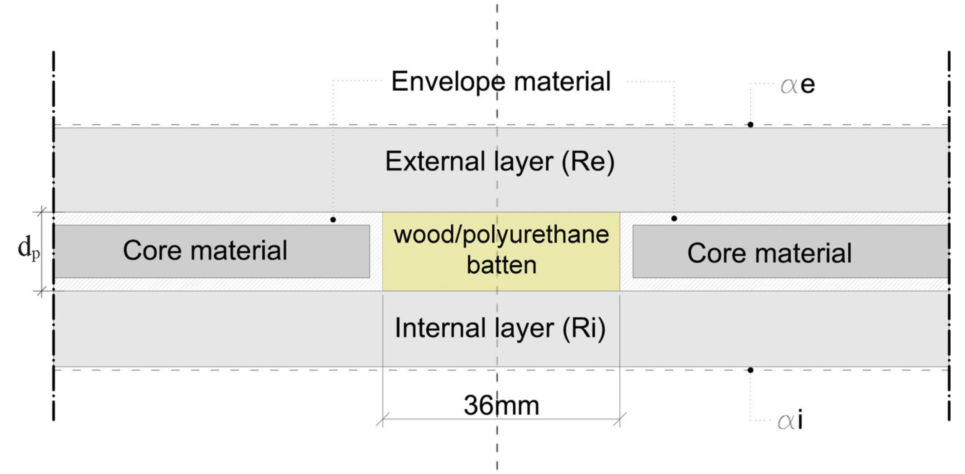
Figure 3.
Model for the numerical calculation of the effective thermal conductivity of VIPs.
Figure 3.
Model for the numerical calculation of the effective thermal conductivity of VIPs.
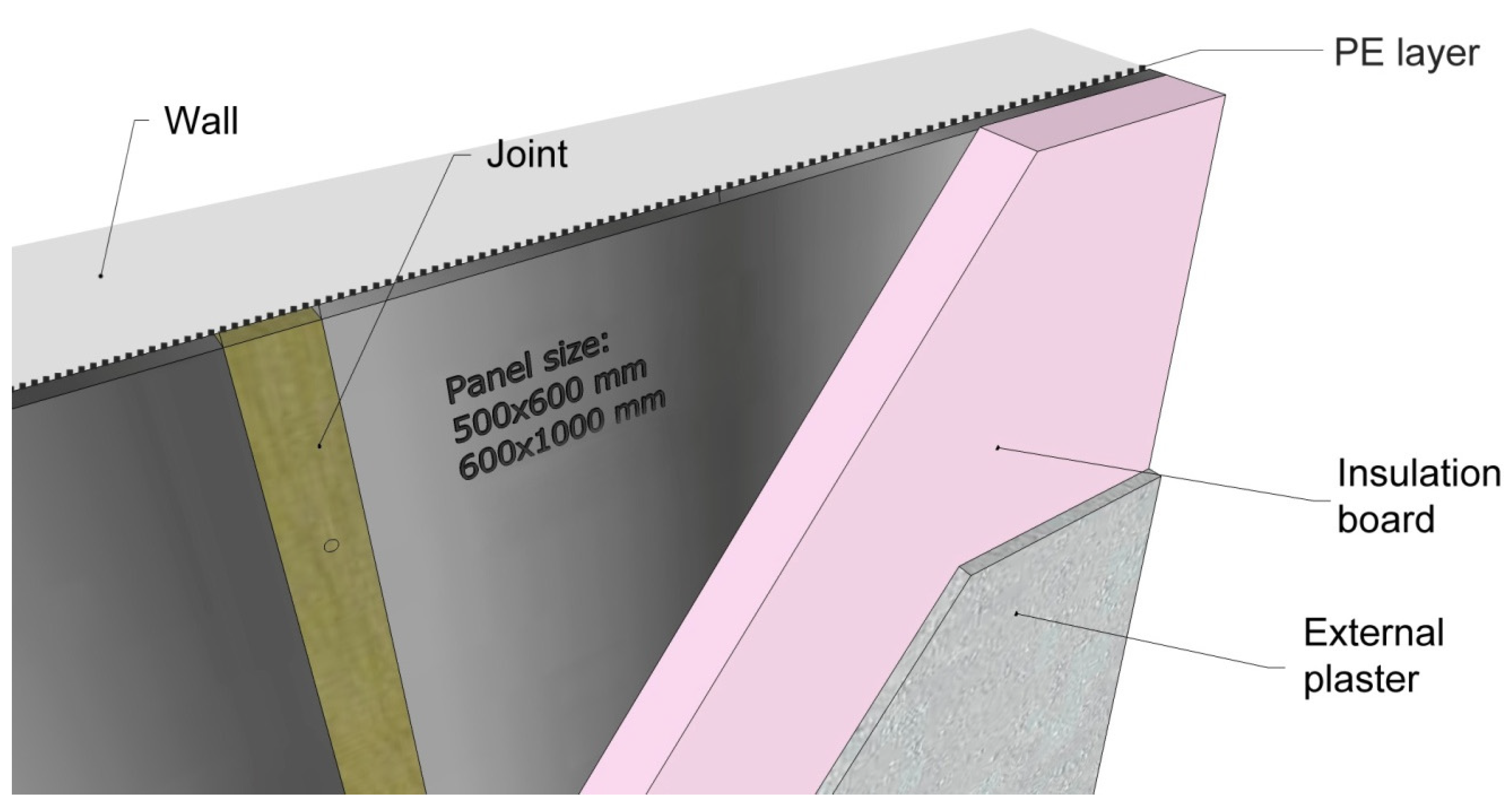
Figure 4.
3D scheme of a typical building insulation configuration.
Figure 4.
3D scheme of a typical building insulation configuration.
The VIP panel was 500 × 600 mm and the value of the equivalent thermal conductivity (λ
COP) used for the numerical simulations was the same one measured for brand B (see
Section 2).
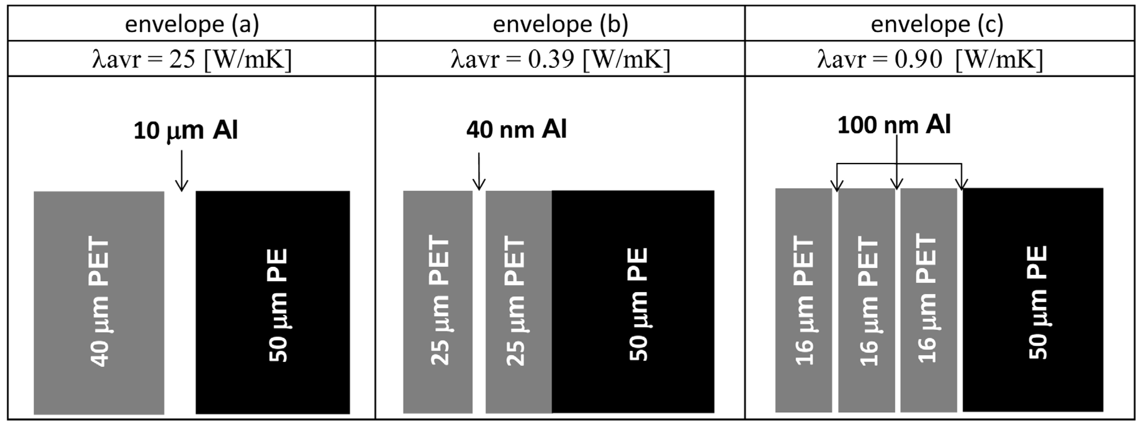
The numerical analysis was repeated for different thermal properties of the membrane that is used to bind the VIP panel. A parametric analysis was carried out considering three different types of envelope [
20]:
a metal foil, consisting of a central aluminum barrier layer, laminated between an outer PET layer (for scratch resistance) and an inner PE sealing layer (case: a);
a metalized film, made of one layer of aluminum coated PET film and an inner PE sealing layer (case: b);
a metalized film, made of three layers of aluminum coated PET film and an inner PE sealing layer (case: c).
Figure 5 schematically shows the envelope structure and summarizes its main features.
Figure 5.
Envelope configurations considered for the numerical simulations [
6].
Figure 5.
Envelope configurations considered for the numerical simulations [
6].
As far as the structural joints are concerned, various arrangements for real building applications were found taken from a literature review (see e.g., [
1,
18,
23]).
In the present study, two typical systems were considered: wood (λ
wood = 0.14 W/mK) and polyurethane batten (λ
PU = 0.026 W/mK) interposed between two adjacent VIPs, as shown in
Figure 3 and
Figure 4. The joints are used in practice to fix additional insulation panels, through dowels, onto a VIP and to fix the VIP onto the rear wall.
Finally, since the thermal bridging is affected by the presence of the two boundary layers (internal, R
i, and external; R
e—
Figure 3 and
Figure 4), different simulations were carried out varying the additional thermal resistance of these two additional layers (R
tot) in the range between 0 to 3.83 m
2K/W.
In other words, the total additional thermal resistance, R
tot, was divided between the external and internal layers, R
i and R
e, respectively. Calculations were then repeated changing these last two parameters in discrete steps, as shown in
Table 3.
The internal and external surface resistances, α
i and α
e, for the horizontal heat flux were assumed to be fixed, and their values were chosen in accordance to EN ISO 6946 [
24]. The temperatures of the external and internal environments adopted in the simulations were always set at 0 °C and 20 °C, respectively.
Table 3.
Thermal resistance of the additional panels (Ri, Re)—values assumed for the simulations (the values related to Ri and Re are shown in bold in the first row and first column, respectively. The values of RTot = Ri + Re are shown in the table).
Table 3.
Thermal resistance of the additional panels (Ri, Re)—values assumed for the simulations (the values related to Ri and Re are shown in bold in the first row and first column, respectively. The values of RTot = Ri + Re are shown in the table).
| Ri + Re [m2K/W] | Ri [m2K/W] |
|---|
| Re[m2K/W] | 1.87 | 0.87 | 0.37 | 0.12 | 0.00 |
|---|
| 1.96 | 3.83 | 2.83 | 2.33 | 2.08 | 1.96 |
| 0.96 | 2.83 | 1.83 | 1.33 | 1.08 | 0.96 |
| 0.46 | 2.33 | 1.33 | 0.83 | 0.58 | 0.46 |
| 0.21 | 2.08 | 1.08 | 0.58 | 0.33 | 0.21 |
| 0.00 | 1.87 | 0.87 | 0.37 | 0.12 | 0.00 |
A first set of simulations was performed for an ideal case in which there were no boundary panels (external and internal, that is: R
i = R
e = 0 m
2K/W) and no structural joints. In such a configuration, the thermal bridge is only caused by the presence of the VIP envelope (“no joint” cases) (It is worth noting that this configuration is the one that is usually investigated and reported in the literature). The aims of this analysis was to compare the results obtained with the numerical model used in this paper with those available in literature [
6], for validating the model itself.
Subsequently, the effect of thermal bridging was assessed taking into consideration the combined influence of both the “VIP panel-edge” node (thermal bridge at the “VIP level”, due to the panel envelope) and the “VIP—joint” node (thermal bridge at the “building level”, due to the structural joints).
In order to quantify these phenomena, the linear thermal transmittance of the thermal bridge (EN ISO 14683 [
25]), was calculated on the basis of the results obtained by means of a steady-state numerical model.
Finally, starting from the knowledge of the linear thermal transmittance and the centre of panel thermal conductivity of VIP, λCOP, a suitably modified U-value of the VIP panel (effective thermal transmittance, Ueff) was assessed, which globally took into account the heat flux through both the structural joints and the multilayer structure.
The calculation procedure, which was conducted accordingly to standard EN 10211-1 [
26], started with the identification of the portion of the panel that was influenced by the thermal bridge, that is with the assessment of the value of “b” (
Figure 6).
The length “b” was chosen to include the entire region in which the heat flux departs from the one-dimensional conditions in the geometrical domain of the model (this check was done on the basis of the results of the numerical model).
The linear thermal transmittance of the thermal bridge between two adjacent panels, ψ
VIP, was then calculated through the following equation:
where, referring to the calculation scheme shown in
Figure 6;
is the overall (actual) heat flux that crosses the surface Sp (dashed area in
Figure 6) of the panel with the thermal bridge (of length lp). θi and θe are the internal and external temperatures, respectively; and qCOP is the centre of panel heat flux per unit length,
(
is the heat flux that would cross an ideal panel with the same area, S
p, but made only of homogeneous VIP material).
Figure 6.
3D scheme of the numerical calculation of the effective VIP thermal conductivity.
Figure 6.
3D scheme of the numerical calculation of the effective VIP thermal conductivity.
The 1-D thermal transmittance of the ideal envelope component without joints, U
1D, can be written as (according to the EN ISO 6946 standard [
24]):
where d
p is the VIP thickness; R
i and R
e are the thermal resistance of the internal and external additional layers, respectively (see
Figure 3 and
Figure 6); and α
i and α
e are the thermal resistances of the internal and external surfaces.
U1D is the thermal transmittance of a multilayer board, in the absence of any kind of thermal bridge, b is the width, in the 2-D geometrical model, over which the U1D value applies (i.e., the simulated panel width).
Equations (1) and (2) clearly highlight that the influence of the thermal bridge depends on the features of the various layers of the wall, as well as on the VIP material, and on the heat transfer coefficients of the surface.
In order to obtain a parameter that is able to describe the overall performance of a multilayer wall with VIP panels, an effective thermal transmittance, U
eff, can be defined as:
Recalling Equations (1) and (2), it is then possible to write:
Finally, an effective thermal conductivity of the VIP panel, λeff,VIP (which accounts for both the “undisturbed” homogeneous material and the thermal bridge at the edges), can be derived from Equation (4).
It is also possible to write U
eff as:
and hence:
λeff,VIP is of practical importance since it allows an easy and immediate comparison to be made between the performance of an ideal, homogeneous panel and that of a real panel with joints.
As already mentioned, a numerical model was built with TRISCO. Due to the thermal symmetry, only one half of the configuration reported in
Figure 4 and
Figure 6 was modelled. In this way, the model provided one half of the linear thermal transmittance Ψ
VIP/2.
The model was tested during a preliminary phase to assure a grid independent solution (this was done accordingly to the EN ISO10211 standard) [
26]. Its reliability was then verified considering the “no joint” configurations and comparing the ψ-values calculated with the TRISCO (the calculations were made for similar conditions—λ
env,VIP, λ
COP, panel thickness—as the cases published in literature) model with those available in literature (see e.g., Baetens
et al. [
6]). The results are not shown here for the sake of brevity).
After these (positive) tests, the numerical model was used to study various configurations.
Figure 7 and
Figure 8 summarize the obtained results.
Figure 7.
ψVIP/2 values (1000 mm × 600 mm VIP panel).
Figure 7.
ψVIP/2 values (1000 mm × 600 mm VIP panel).
In particular, the linear thermal transmittance of the thermal bridge, ψ
VIP/2, is plotted
versus the total thermal resistance of the internal and external boundary layers (that is, R
i and R
e) in
Figure 7.
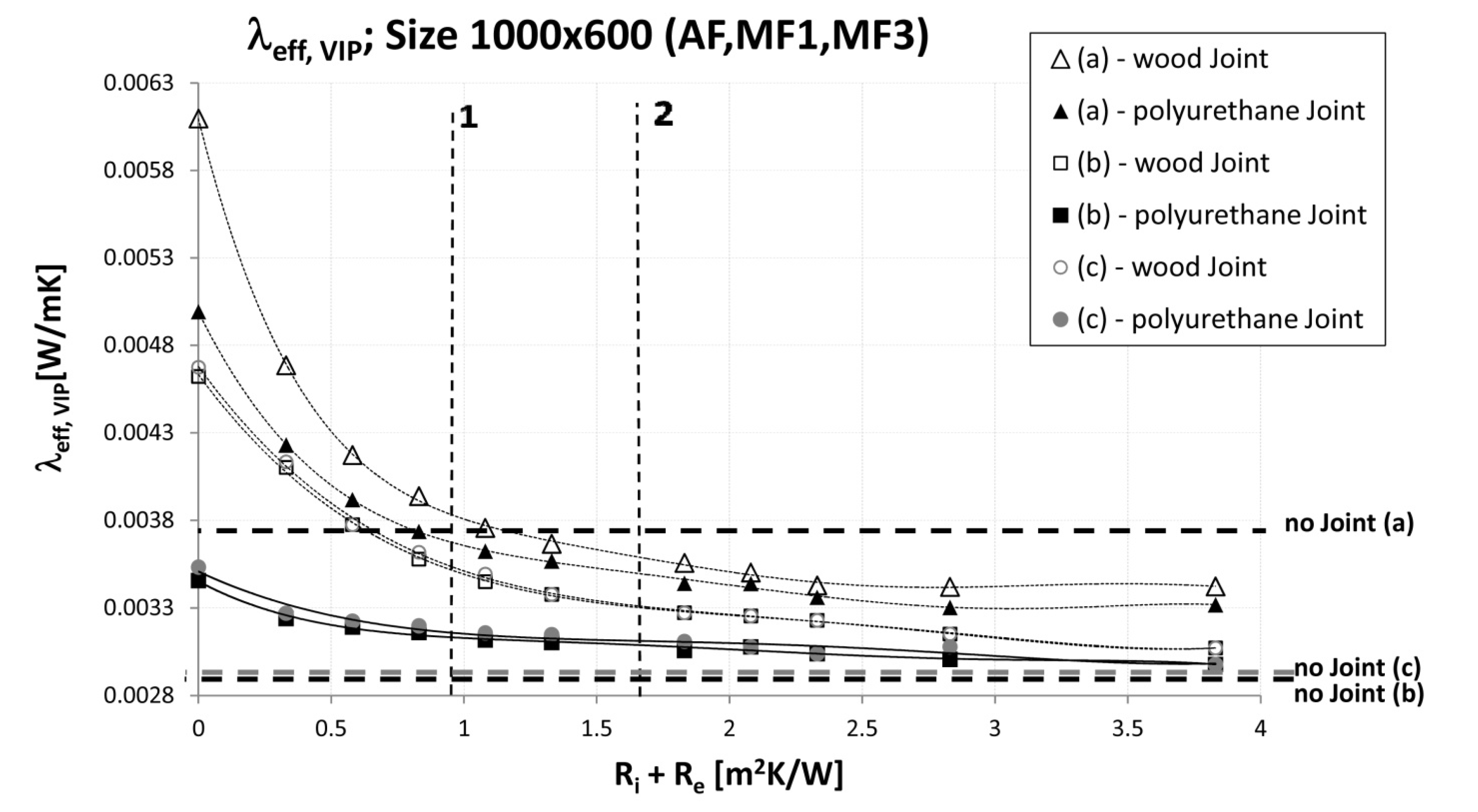
Figure 8 instead shows analogous profiles of the effective thermal conductivity of the VIP panel, λ
eff,VIP.
Various curves are plotted on these figures, each of which refers to a different case/configuration (different envelope materials—(a), (b), (c)—and different structural joints—Wood, Polyurethane).
Moreover, for comparison, the values related to the cases without any structural joint and without additional layers (i.e., Ri + Re = 0) are also shown as horizontal dashed lines (“no joints” cases).
Figure 8.
λeff values (1000 mm × 600 mm VIP panel).
Figure 8.
λeff values (1000 mm × 600 mm VIP panel).
4. Discussion
The results of the numerical analysis demonstrate that the influence of thermal bridging due to the structural joints is remarkable compared to the effects of the VIP envelope alone, without the joints (these last cases are represented by horizontal dashed lines in
Figure 7 and
Figure 8).
Considering all the cases without additional layers apart from the VIP panel (that is for R
i + R
e = 0,
i.e., points lying on the Y-axis), it is possible to see (
Figure 7) how the introduction of a structural joint significantly lowers the performance of the super-insulation materials. Depending on the VIP envelope conductivity (a, b, c), the ψ
VIP/2 value for the configurations with a wood joint is about 3.5 (“a”, high conductive VIP envelope) to 25–35 times (for “c” and “b” respectively) higher than that of the case with the envelope alone (no joint case). When the polyurethane joint is considered, a smaller increase of the ψ
VIP/2 value is observed, especially when the VIP envelope has a lower conductivity level (b, c).
As previously mentioned, this configuration is the one that has been investigated most frequently so far. However, it should be considered that it is also the one which is unlikely to be found in practice, that is, where the VIP panels are located inside a multilayer wall for installation purposes and protection from accidental damage.
If the effects of the layers that bound the super-insulation panels are considered, it is visible from
Figure 7 and
Figure 8, that the behavior of the wall package can change significantly.
As expected, the ψ
VIP/2 parameter (
Figure 7) assumes the maximum value for null additional resistances (R
i + R
e = 0, for just the VIP panel alone and the joints) and tends to decrease as the thermal resistance of the bounding layers increases.
For the (b) and (c) cases, ψVIP/2 approaches the values shown for the “no joint” configurations when the additional thermal resistance exceeds 4 m2K/W (which, to have a practical idea, corresponds to a total thickness of a good traditional insulation material of about 15 cm). Instead, when the (a) configuration is used for the VIP membrane, ψVIP/2 becomes lower than the “no joint” values for an additional total thermal resistance of about 0.50–0.75 m2K/W.
As expected, the polyurethane joints (
Figure 7) show better insulation properties than those of the wood joints. However, the difference depends to a gear extent on the type of the VIP envelope material and on the wall structure. The less the envelope is conductive, the less the difference in performance between wood and polyurethane.
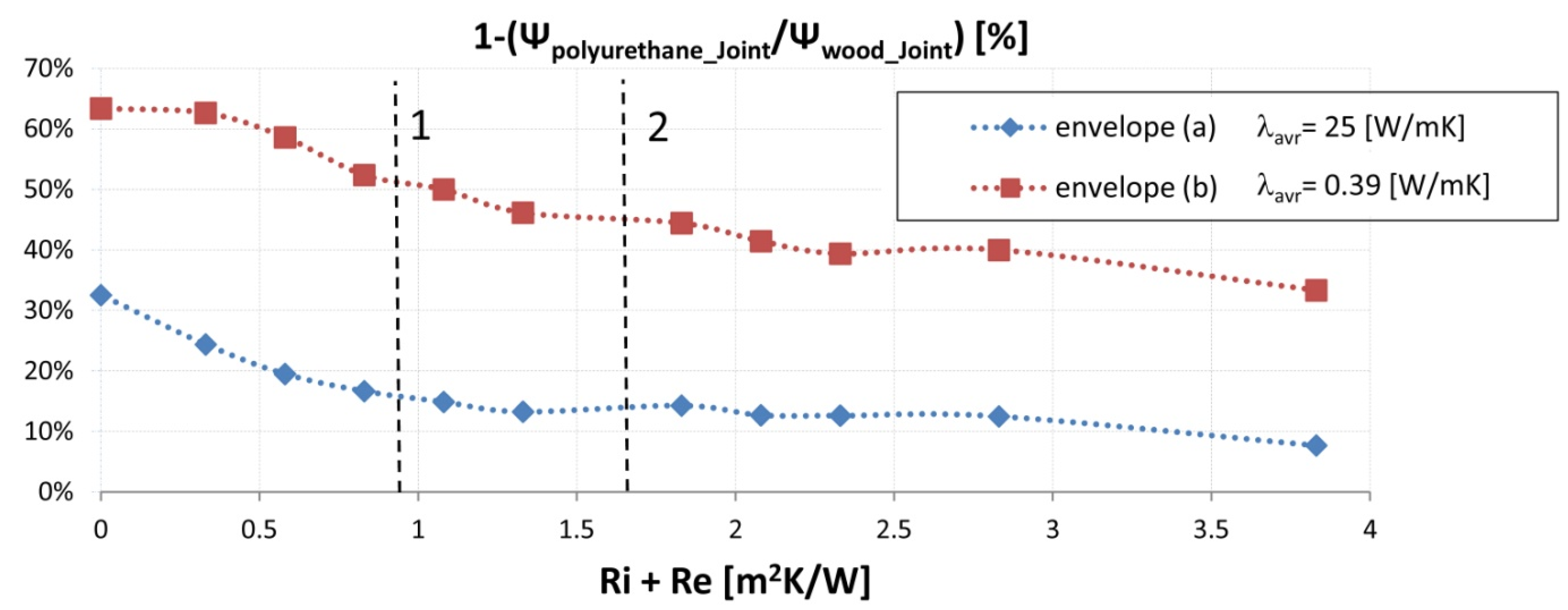
The relative decrease in ψ
VIP/2, when switching from wood to polyurethane joints, is plotted in
Figure 9 versus the total thermal resistance of the additional layers. One curve (square symbols) refers to the case of an (a) envelope, while the other (diamond symbols) is related to a “b” envelope. A reduction of about 65% is achieved for the case with an (a) envelope when there are no boundary layers (R
i + R
e = 0). This figure reduces to about 35% if the envelope is made of (b).
Besides the effect of the membrane material, the difference in ψVIP/2, between the polyurethane and wood joints, also decreases as the total thermal resistance of the layers surrounding the VIP increases (i.e., when the influence of the thermal bridge due to the joints become less important). For an Ri + Re of about 3 m2K/W, the previous percentages become 40% and 13% for (a) and (c), respectively.
Therefore, the use of polyurethane as a structural joint results to be particularly beneficial when either a high performing material is used for the VIP membrane or the total thermal resistance of the boundary layers is low (see
Figure 7 and
Figure 9).
Figure 9.
Difference between ψ values for wood and polyurethane joints considering (a) and (b) envelopes (1000 mm × 600 mm VIP panel).
Figure 9.
Difference between ψ values for wood and polyurethane joints considering (a) and (b) envelopes (1000 mm × 600 mm VIP panel).
In order to have an idea of the effects of the various joint configurations on the performance of realistic wall structures and which could be used for typical building renovations and/or constructions, two multilayer components were considered.
Case 1 consisted of 0.25 m thick concrete and 0.03 m XPS (corresponding to an additional total thermal resistance, besides the VIP panel, of: Ri + Re = 0.98 m2K/W);
Case 2 consists of a 0.30 m brick cavity wall (0.12 m each brick layer and 0.06 m air cavity), 0.03 m XPS and three plaster layers with a thickness of 0.02 m each (corresponding to an additional total thermal resistance, bedsides the VIP panel, of: Ri + Re = 1.63 m2K/W).
The values of the total additional thermal resistance of such configurations are given in
Figure 7,
Figure 8 and
Figure 9 by means of vertical dashed lines, denoted with the labels “1” and “2”.
It is possible to see (
Figure 7) that the ψ
VIP/2 values for the (a) envelope with joints are lower than those related to the “no joints” reference case (it is worth recalling that the “no joint” configurations refer to a case without any additional thermal resistance), as the first is in the range of about 0.0014–0.025 W/mK and the second is around 0.035 W/mK.
The situation is instead reversed for the (b) and (c) envelopes. For (b), the ψVIP related to walls “1” and “2”, considering the wood joint, is around nine and five times higher than the values of the “no joint” case ( the latter being around 0.002 W/mK) (for the polyurethane joint these figures become 4.5 and 3.5 times higher, respectively).
Similar results were found for the (c) envelope. Analogous conclusions can be drawn when the λ
eff,VIP values are analyzed (
Figure 8).
This parameter has the advantage of giving/offering a direct and prompt comparison of an ideal case of a wall made with a homogeneous layer of VIP panels and the actual case of a wall with VIP panels installed with structural joints.
The rationale behind this quantity is that the effect of the thermal bridge, instead of being accounted for by means of its linear transmittance ψ (as usually done), is taken into consideration by virtually increasing the equivalent thermal conductivity of the material (as if the thermal bridge were evenly “spread” over the entire panel).
The calculation of λeff,VIP requires a hypothesis on the incidence of the thermal bridges (that is, their total length) over the whole panel surface. An assumption about the shape and the size of the VIP panels is therefore needed. For the analysis here presented, a 1000 mm long and 600 mm wide board was used.
It is worth noting (
Figure 8) that the combination of the thermal bridge effect (related to the envelope and the structural joints) and of the boundary layers leads to an effective “overall” thermal conductivity of the super-insulation material than spans from about 0.0030 to 0.0034 W/mK for the best configurations (corresponding to the case in which a very high total thermal resistance of the additional boundary layers is adopted: R
i + R
e ≈ 4 m
2K/W).
Compared to the equivalent centre of panel thermal conductivity, λCOP, (which is around 0.0028–0.0029 W/mK, for the materials considered for this analysis), the effective thermal conductivity is about 7% to 21% higher. λeff,VIP could be as high as 0.0060 W/mK if a configuration with an (a) envelope, wood joints and no additional layers were used.
In the case of more realistic configurations (i.e., cases “1” and “2”), the percentage increase of λeff,VIP compared to λCOP is about 31%–25% using polyurethane joints and about 39%–29% for a wood joint.
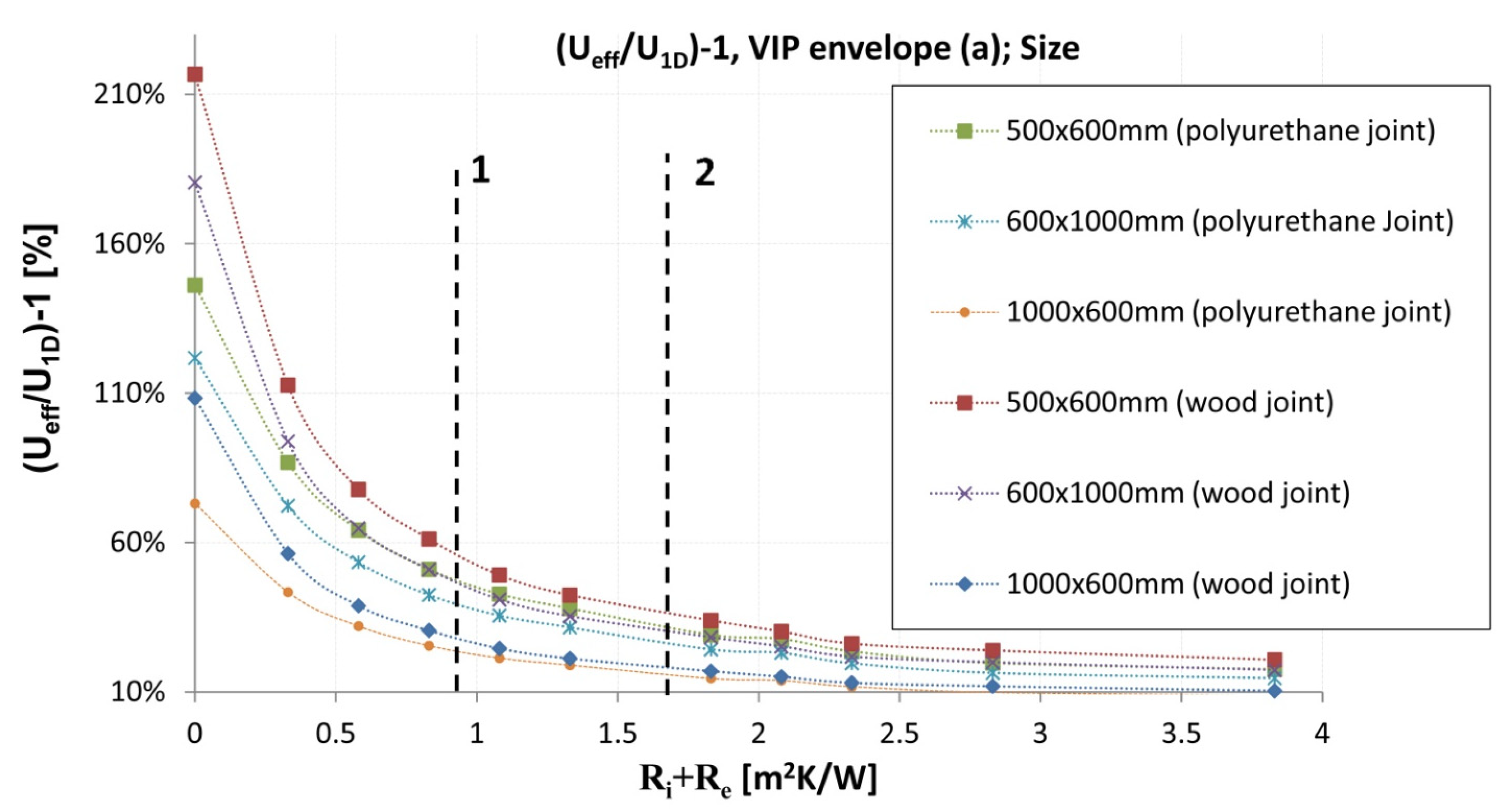
Finally, the influence of the shape and size of the VIP panel on the overall performance of the wall is shown in
Figure 10, where the relative variation of the actual, effective U-value of the wall (
i.e., U
eff) with respect to the U
1D value, is plotted
versus the total thermal resistance of the boundary layers (R
i + R
e).
As expected, as the number and the extent of the linear thermal bridges are lowered, the performance of the super-insulation material increases. The board shape/size becomes more and more influential as the thermal resistance of the boundary layers becomes lower and the thermal properties of the VIP envelope and of the structural joints become poorer.
Figure 10.
(Ueff/U1D)-1 values for VIP panel envelope (a) for three different sizes and shapes.
Figure 10.
(Ueff/U1D)-1 values for VIP panel envelope (a) for three different sizes and shapes.
5. Conclusions
Super-insulation materials show promising features and can be/constitute an effective solution for the energy retrofitting of existing buildings as well as for the construction of new highly efficient houses, without compromising space utilization. They, in fact, allow very low U-values to be reached with reduced wall thicknesses.
Nevertheless, the use of VIPs also represents a challenge for engineers and architects. The rating of the performance of the material, through the center of panel equivalent thermal conductivity alone, is insufficient to provide designers with information that is useful to represent the actual behavior of VIPs when applied to real buildings. Moreover, the laboratory measurement of λ
COP can reveal to be tricky, due to its very low value. On the basis of the outcomes obtained from the research developed so far, it is possible to highlight that the following key points need to be considered carefully when VIP panels are used in wall construction:
- (1)
reliability of the declared nominal thermal conductivity of the panel;
- (2)
durability and performance decay due to vacuum loss;
- (3)
assessment of the overall, actual performance of the whole wall system (with multiple layers and joints).
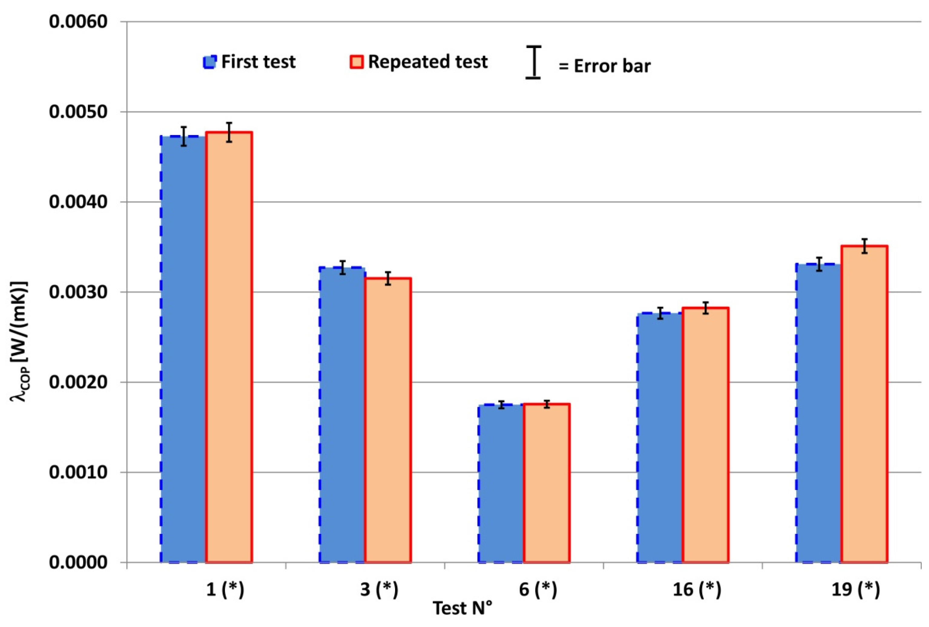
As far as the first topic is concerned, it should be pointed out that the measurement of the equivalent thermal conductivity at the center of panel (a parameter which is typically/frequently used to label traditional insulation materials), though apparently trivial, is in practice quite difficult to carry out in an accurate way. The very low thermal conductivity of the material under analysis, in fact, poses many challenges to certified laboratories and the resulting measurement accuracy needs to be assessed carefully during each test (for all the tests performed in the present study, the accuracy was around 2%–3%). In order to assure a proper accuracy and repeatability of the tests, care needs to be taken in the choice of the sample size, sample positioning and measurement conditions (e.g., temperature differences).
The experience attained on five different VIP panels has shown that the measurement repeatability was almost always satisfactory (just for one case was the variability between two tests similar to the measurement accuracy). However, it should be underlined that measurements repeated for different samples of/on the same VIP material (same manufacturer, same panel type) sometimes provided significantly dissimilar values of λCOP. The most evident case is the one related to “Manufacturer A—panel type 1”. For this material, tests performed on five, theoretically identical samples showed λCOP values ranging from 0.0026 W/mK to 0.0047 W/mK. The results for the other panel types also presented a remarkably high variability of the samples.
The reason for such behavior can be due to both the construction process (not sufficient constancy of the manufacturing process, e.g., a probable degree of vacuum that can change from one panel to the other) or to a variability of the measurement conditions. As far as this last issue is concerned, it should in fact be noted that the surface of VIP panels is never perfectly even or flat, and this could determine a variability of the contact thermal resistances between the hot/cold plates of the measurement apparatus and the sample under test. Such variability can determine a non-negligible variation of λCOP for different samples of the same material.
Further research is needed in relation to this point, since λCOP is a parameter that is universally adopted to score the performance of super-insulation material and which therefore has a huge impact on the material market and on the design processes.
The performance decay due to loss of vacuum (which can occur either during the installation process, because of mechanical damage, or during the operational phase, for ageing) implies an increase in the equivalent thermal conductivity of the super-insulation panel of about 400%–500% with respect/compared to the pristine material. The findings obtained during the present research have confirmed some previous studies and point out that attention should be paid to VIP durability.
Nevertheless, it is worth noting that, even when damaged, a VIP panel has a lower equivalent thermal conductivity than the best traditional insulation materials currently on the market.
Finally, the effects of the actual installation process, which implies the use of structural joints to fix the boards and at least one external and one internal layer between which the VIP panel is located/positioned, are significant for the ultimate performance of a wall and must be assessed properly.
It has been demonstrated that a significant underestimation of VIP performance, at the building level, is obtained if this assessment is not conducted in an appropriate way.
The most important parameters that can affect the ψ values of the thermal bridges, due to structural joints, in actual applications are: the overall thermal resistance of the wall, the thermal properties of the joint and the thermal conductivity of the VIP envelope.
In short, in order to correctly evaluate the economic and energy effectiveness that can be achieved using high performance insulation materials in real building applications, it is impossible to either disregard the thermal bridging effect or neglect the specific structure of the wall in which the panel is inserted.


