Article

Sintered Nickel Powder Wicks for Flat Vertical Heat Pipes

Department of Energy and Process Engineering, Norwegian University of Science and Technology, Kolbjørn Hejes vei 1a, 7491 Trondheim, Norway
*
Author to whom correspondence should be addressed.
These authors contributed equally to this work.
Energies 2015, 8(4), 2337-2357; https://doi.org/10.3390/en8042337
Submission received: 12 January 2015 / Revised: 26 February 2015 / Accepted: 16 March 2015 / Published: 25 March 2015

Abstract

:
The fabrication and performance of wicks for flat heat pipe applications produced by sintering a filamentary nickel powder has been investigated. Tape casting was used as an intermediate step in the wick production process. Thermogravimetric analysis was used to study the burn-off of the organic binder used and to study the oxidation and reduction processes of the nickel. The wicks produced were flat, rectangular and intended for liquid transport in the upwards vertical direction. Rate-of-rise experiments using heptane were used to test the flow characteristics of the wicks. The wick porosities were measured using isopropanol. The heat transfer limitation constituted by the vapour static pressure and the capillary pressure was discussed. The influence on wick performance by using pore former in the manufacturing was studied. When Pcap/Psat > 1, the use of a pore former to increase the wick permeability will always improve the wick performance. When Pcap/Psat < 1, it was shown that if the effective pore radius and the permeability increase with an equal percentage the overall influence on the wick capacity is negative. A criterion for a successful pore former introduction is proposed and the concept of a pore former evaluation plot is presented.

1. Introduction

The concept of heat pipes was first described in 1942, but the real development of heat pipes started in the 1960s [1]. Properly designed heat pipes can transport heat at very high rates with a small temperature difference between the cold and the warm end. This is possible because the heat transport inside the heat pipe is based on evaporation, transport and condensation of a suitable working fluid, and thereby also obtaining an apparent thermal conductivity several hundred times that of solid materials such as copper [2]. The heat pipe interior contains a wick, in which the condensate returns from the condenser section to the evaporator section. The driving force in the condensate transport process is the capillary pressure created by the wick and working fluid interaction, in some cases the capillary pressure is supported by the gravity force. The gravity force contributes to the transport process when the condenser section is located above the evaporator section, i.e., the heat pipe is gravity-assisted [3]. The heat pipe is gravity-opposed when the condenser section is located below the evaporator.
Wicks can be produced by several different techniques and from different materials, such as woven metal wires, metal foams, sintered metal powders, or they can be made as grooves in the wall of the heat pipe [4]. Bimodal wicks are made by adding metal powders to metal foams or felts [5,6,7]. In some cases the wick capacity can be improved by creating internal arteries inside it, forming low-friction flow paths for the liquid [4]. De Schampeleire et al. [3] stated that “the number of possible wick types is virtually endless”. They investigated wicks for water/copper heat pipes having 6 mm outer diameter and 200 mm length, for cooling of electronic devices. Specifically, a novel wick made of metal fibers was compared to more traditional wicks made of a screen mesh and a sintered powder, respectively. Under gravity-assisted conditions the screen mesh wick performed best, because of its superior permeability. High permeability means low frictional pressure loss for the fluid flowing through the wick. In the gravity-opposed orientation the screen mesh wick and the metal fibre wick both outperformed the sintered powder wick [3]. However, the properties of sintered powder wicks can be modified and improved by use of pore formers. The pore former, usually an organic material, is mixed with the metal powder and thereafter “burnt off”, leaving a void behind. The burn-off process using an air or oxygen atmosphere is usually a separate process prior to the sintering. The pore former will normally increase the pore size and thereby also increase the effective pore radius of the wick. Different heat pipe applications and different working conditions require different wick properties, it is therefore important to know how the different production parameters such as pore formers affect the wick properties. Li et al. [8] investigated experimentally how much the forming pressure and the use of a microcrystalline cellulose (MCC) pore former affected the wick porosity and capillary pumping performance of a sintered powder wick for loop heat pipes, and developed a correlation between porosity, forming pressure and MCC addition. The use of a pore former for wick capacity improvement is analysed further in the current study. A criterion for successful pore former introduction is derived, and the novel concept of a pore former evaluation plot is presented. The ideal pore former can be totally removed from the wick structure, for instance by heat treatment (burn-off) and/or by chemical treatment. The suitability of pure graphite powder and carbon fibers as pore formers are considered in the current study and the required burn-off temperature for graphite powder is determined experimentally. Information about the required burn-off temperature is essential when pore former material is to be selected, if the burn-off temperature is too high the wick material may be damaged.
Compatibility with the working fluid is often the main wick material selection criterion, and the wick material is often a metal. Incompatibility can lead to generation of non-condensable gases, which can displace the working fluid and thereby hamper the heat transfer [9]. However, material compatibility is not sufficient. Proper thermal and/or chemical cleaning of the wick is equally important in order to avoid corrosion, non-condensable gases and to ensure proper wetting of the wick by the working fluid [10,11]. The importance of the wick in the cleaning process is emphasized by the fact that the total surface area of the wick is much larger than the surface area of the container; the surface of the wick can therefore contain much more adsorbed unwanted components than the container wall.
Wicks of sintered nickel powder have been used for many years in heat pipes [1,4]. Nickel has relatively high thermal conductivity, which is an advantage when heat is to be conducted across the wick as in traditional heat pipes. For loop heat pipes high thermal conductivity of the wick is a disadvantage [8,12]. Nickel is compatible with alkali metals, frequently used as working fluids for high temperature heat pipe applications [1]. In the current study a wick of sintered nickel powder was developed, and its suitability for gravity-opposed operation with potassium as working fluid is evaluated. Specifically, the intended application was a special type of heat pipe, having a flat wick in the evaporator section only. Figure 1 shows the working principle.
Figure 1. A flat wick attached to a solid substrate subject to a uniform heat flux causing liquid evaporation from the free wick surface. Liquid (condensate) is pumped by the wick from a reservoir at the bottom of the wick. The experiments utilized to characterize the wick in this study were performed without the heat addition and without the solid substrate.
Energies 08 02337 g001
The filamentary nickel powder Inco Type 255 is a popular raw material for wick production [5,8,13]. The filamentary particles make it possible to produce wicks with porosities far above the porosity of any wick produced of monodisperse spherical particles. The porosity of a wick produced from monodisperse spherical particles is theoretically between 26% and 47%, while the porosity of a wick of filamentary particles can be up to ca. 90% [13]. The wick developed in the current study was made of sintered Inco Type 255 nickel powder. The following parameters are known to affect the properties of sintered Inco Type 255 nickel powder [14]:
  • Sintering time.
  • Sintering temperature.
  • Sintering atmosphere.
  • Type and amount of pore former (spacing agent).
  • Pressure from weights applied during sintering (forming pressure).
Long sintering time, high sintering temperature, and high forming pressure will in general lead to compact wick structures, having low porosity, low permeability and a small effective pore radius. The minimum sintering time, temperature and forming pressure providing sufficient mechanical strength should therefore be the best choices in order to maintain an open, high porosity wick structure. The sintering atmosphere is very important when nickel powder is used, because of the susceptibility of nickel to oxidise at high temperatures. The surface properties of nickel oxide will be different from that of pure nickel, and this will in general affect the interfacial tensions and the contact angle between the solid and the working fluid. In order to avoid oxidation of the nickel, the sintering of nickel powder can be carried out in protective/reducing gas atmosphere [12] or in vacuum [7]. Similarly, nickel oxides, e.g., formed during burn-off, can be reduced to pure nickel by heat treatment under a reducing atmosphere such as H2 (5 vol%) and N2 (95 vol%) [14]. The mass increase and colour change from grey to green indicate nickel oxide formation, and vice versa for the reduction. Thermogravimetric analysis (TGA) was utilized in the currrent work to study the oxidation of the nickel powder, burn-off, and to study reduction of nickel oxide in a 5% H2 + 95% N2 atmosphere. Such data were needed in the preparation of the burn-off, sintering and oxide reduction programs.
The wick structure has to be robust to be able to withstand handling and thermal strains and stresses, especially important for high temperature heat pipes and when the heat load is unilateral. In the current study a robust wick was obtained utilizing tape casting [15] as an intermediate step in the wick production. The required burn-off time and temperature level for the removal of the additives used in the tape casting were determined by thermogravimetric analysis, and are reported.
Good thermal contact between the wick and the heat pipe wall reduces the overall heat transfer resistance from the outside of the evaporator to the working fluid. The thermal contact resistance between the wick material and the evaporator surface is eliminated when the wick is sintered to the evaporator surface. Burn-off and sintering directly on the evaporator surface was investigated experimentally in this study.
Wicks for heat pipe use are usually characterized by their porosity, permeability, and effective pore radius related to a specific fluid. A standardized method for porous samples can be applied for the porosity measurements [16]. Permeability can be measured in forced flow experiments [17], but has also been determined together with the effective pore radius in spontanous free flow experiments, i.e., rate-of-rise experiments [13,18]. The rate-of-rise experiment was chosen in the current study. Model fluids (e.g., acetone, heptane, methanol) are often utilized in rate-of-rise experiments [13], especially when the real working fluid is hazardous (e.g., alkali metals). Heptane was chosen in the current study. Permeability is independent of the type of fluid, but the effective pore radius is not. In order to convert the effective pore radius from one fluid to another, the contact angles of the respective fluids on the wick powder surface are required. The contact angle of the model fluid (heptane) on porous nickel was derived from capillary rise experiments, as described by Hiemenz [19]. According to Hiemenz [19], the capillary method for contact angle determination “is not highly reliable, but preferable compared to any technique based on the exterior surface of the plug as a liquid support”. The “plug” is in this case the wick. Alkali metals are known to have “strong wetting characteristics” against metals [20]. Hence, the contact angle of potassium on nickel was assumed to be zero [21].
The heat transfer capacity of heat pipes can be restricted by many different heat transfer limitations, which have been given considerable attention in the literature [4,22]. The current paper presents and analyzes a heat transfer limitation which has not been given attention previously; the static pressure limitation. It is shown theoretically how the static pressure limitation will limit the performance of the designed nickel powder wick with potassium as working fluid. To summarize, the following topics are investigated in this study:
  • Method of fabrication of the wick.
  • Selection of burn-off and sintering temperature programs from thermogravimetric analysis.
  • Determination of the wick characteristics.
  • Prediction of the wick maximum heat transfer capacity with potassium.
  • Criterion for pore former selection.

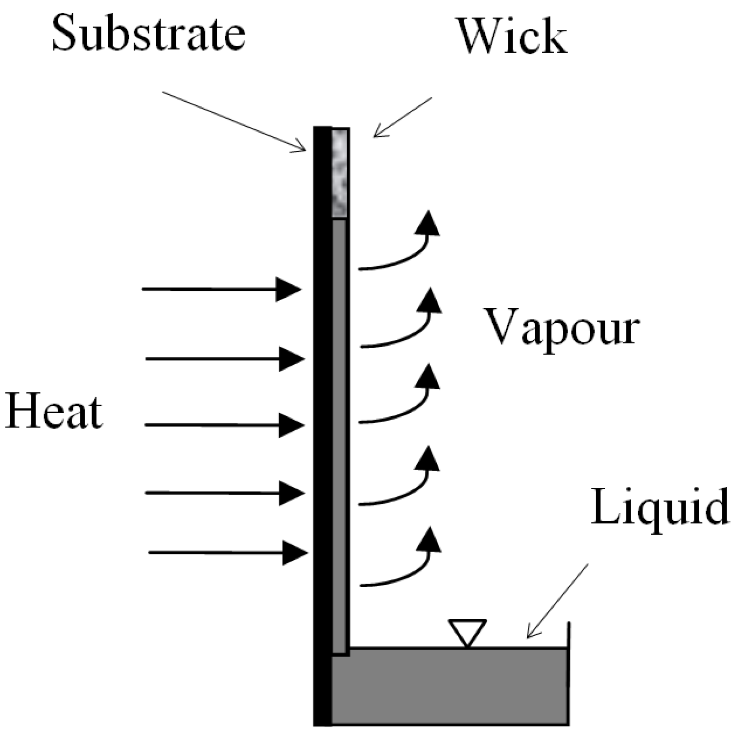
2. Method of Fabrication of the Wick

Wicks were made by sintering pure Inco Type 255 nickel filament. During this study many wicks were produced by different methods (tape casting or mould, with or without pore former). A production method based on tape casting of a slip without pore former was found to be the most successful with regards to the mechanical properties of the wick. In the following this approach is described in detail, as well as the testing and results for a wick produced by this method. Some results from the work with pore former have also been included. Moulding was attempted, but sufficient mechanical strength was not achieved, hence this method was considered inferior.
In the tape casting, a modified batching procedure for “High-surface-area oxide powder, oxidizing sintering procedure” [15] was used, summarized as: Sinter powder (Inco 255), distilled water and dispersant (Darvan C) were mixed by rolling for about 12 h. A binder (polyvinyl alcohol), a plasticizer (polyethylene glycol) and a defoamer (polypropylene glycol) were then added to the mixture, and the mixture was mixed by rolling for an additional 12 h, after which it was ready for tape casting using a tape casting machine. The tape casting produced a thin (0.2–0.3 mm thick) tape of the mixture. The tape was let to dry for about 12 h in ambient air atmosphere, and was next cut into pieces of desired size. Due to shrinkage during subsequent burn-off and sintering the pieces had to be cut 20%–30% larger than the desired final wick size. The desired wick thickness was achieved by stacking a number of tape pieces on top of each other. For the wick presented in this paper 16 layers of tape were required in order to have a total thickness of 4 mm before burn-off and sintering.
In order to achieve good contact between the tapes and sufficient mechanical strength of the wick, it was necessary to apply pressure upon the pile of tapes during burn-off and sintering. Alumina weights which provided a pressure of 1,300 Pa were used. Ideally, the wick should be sintered directly onto the evaporator surface of the heat pipe as this would eliminate thermal contact resistance between the wick and the evaporator surface. Burn-off and sintering directly on the evaporator surface was tested, but failed because of incomplete burn-off, probably caused by insufficient gas diffusion in the pile of tapes which were covered by the heat pipe walls and the alumina weights. It was therefore decided to produce the wick outside of the heat pipe, and thereafter attach it to the evaporator surface by a suitable method. Following this new approach, the pile of tapes was put on an alumina plate, and the weights put on top of the pile. This was then all put in the oven which had continous synthetic air flushing for effective burn-off of the organic material. The burn-off and sintering temperature program was developed from information from thermogravimetric analysis (TGA), together with known sintering temperature requirements for a mechanical strong wick.

3. Selection of Burn-off and Sintering Temperature Programs from Thermogravimetric Analysis

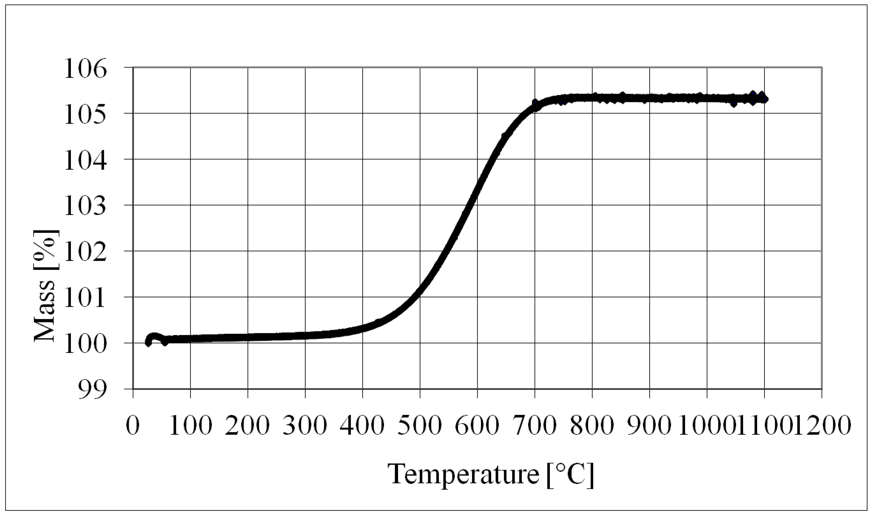
  • Thermogravimetric analysis of pure Inco 255 nickel powder in air was carried out to study the oxidation.
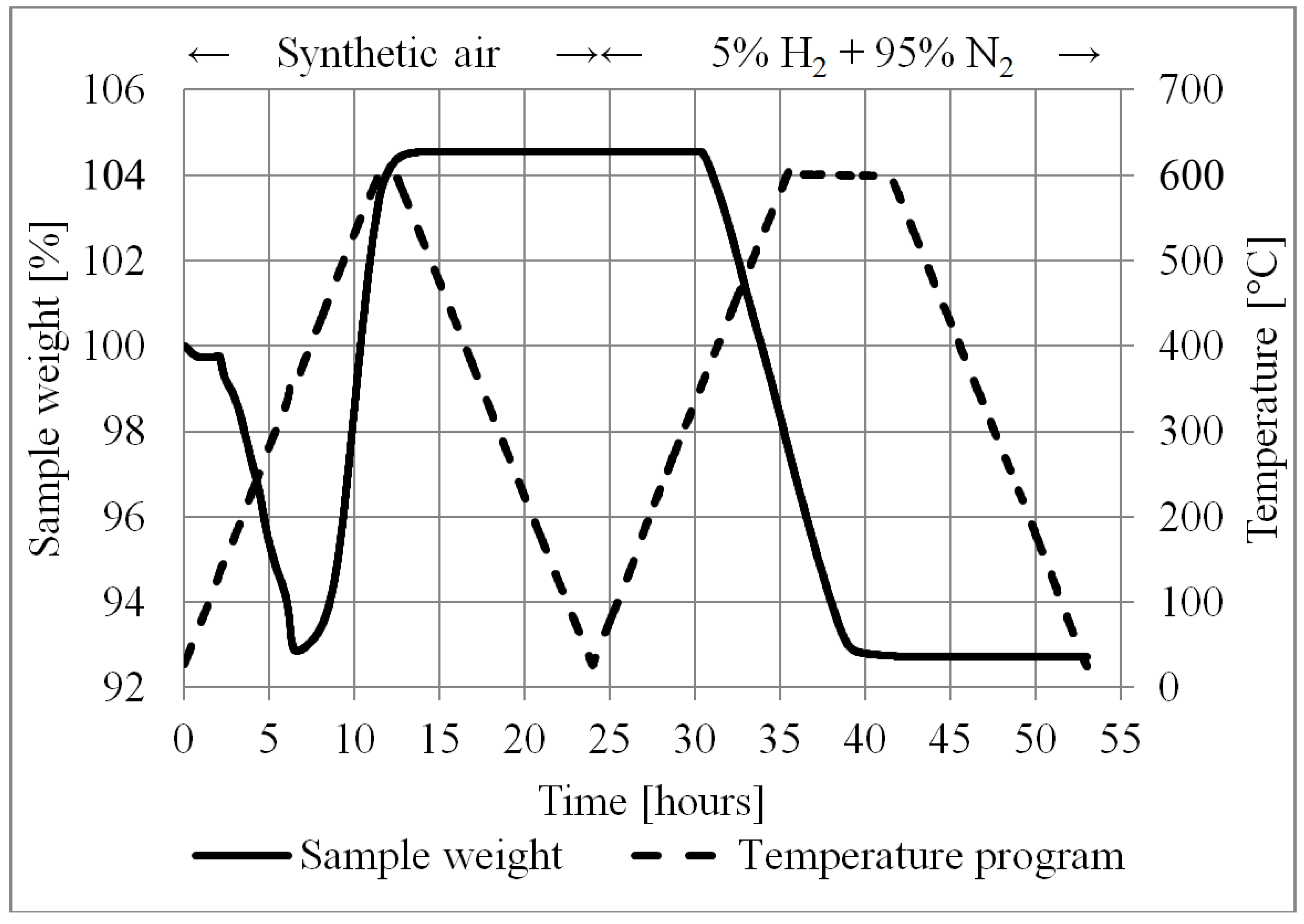
  • Thermogravimetric analysis was carried out for the tape cast tape in order to determine the programs for burn-off and reduction. In this test a 900 µL crucible was filled with approximately 40 layers of tape. The burn-off TGA was carried out using synthetic air atmosphere, and the reduction in a H2 (5%) and N2 (95%) atmosphere.
  • A thermogravimetric analysis with pure graphite powder in air was performed. Pore former was not used in the fabrication of the final wick presented in this study, but some work was performed to analyse the suitability of the graphite powder as pore former. Graphite was selected because it leaves very little residues after burn-off. The graphite powder (from Sigma-Aldrich) had particle sizes smaller than 20 µm.
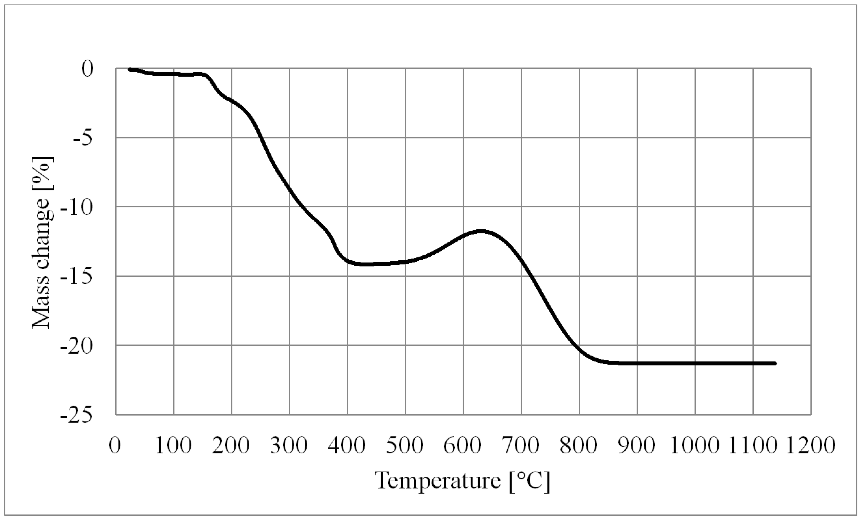
  • A thermogravimetric analysis was also performed for the burn-off of a tape casted tape consisting of approximately equal amounts of Inco 255 nickel powder and graphite powder, plus the tape casting additives.
The results from these four TGA experiments are presented graphically in Section 5—Results and Discussion.

4. Determination of the Wick Characteristics

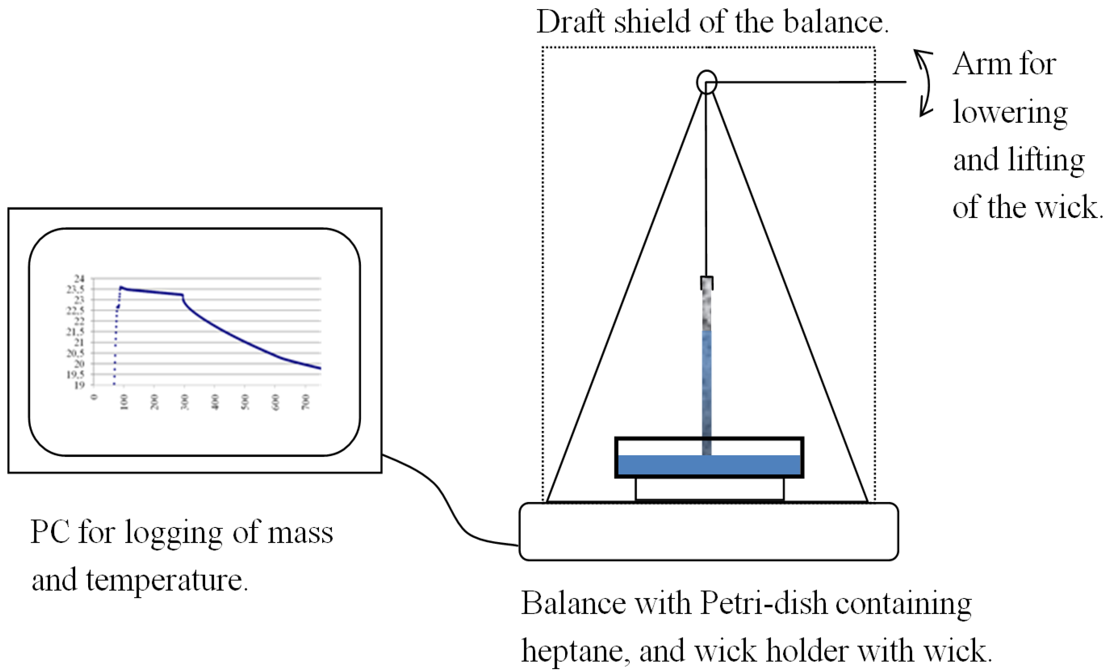
4.1. Capillarity and Flow Characteristics

When a wick is used for liquid transport in the vertical upward direction as shown in Figure 1, its capacity is highly dependent on the effective pore radius and the permeability of the wick structure. The driving force is the capillary pressure, which is a function of the liquid wetting, the liquid surface tension and the pore radius of the wick. The wetting of a solid by a liquid is often expressed by the contact angle. The effective pore radius includes the contact angle information and is defined from a capillary tube model [13]:
Δ P c a p = 2 σ cos ( θ ) r = 2 σ r e f f
The relation between the effective radii of two fluids having different contact angles is:
r e f f , f l u i d 1 r e f f , f l u i d 2 = cos θ f l u i d 2 cos θ f l u i d 1
In the wick the primary forces opposing the capillary pressure are the hydrostatic pressure and the frictional pressure drop of the flow. Of less importance are fluid momentum changes and friction between the liquid and the substrate, both disregarded in the present analysis. The hydrostatic pressure of the liquid column can be expressed as:
Δ P g = ( ρ l ρ v ) g H ρ l g H
where H is the height of the liquid level in the wick relative to the fluid bath. The pressure drop due to friction is calculated from Darcy’s law [13]:
d P f d y = V ˙ μ κ = m ˙ μ κ A c ρ
The highest mass flow rate is at the liquid inlet end (i.e., bottom) of the wick. For a constant evaporation rate per unit height of wick, the mass flow rate in the wick becomes a linear function of position (y):
m ˙ ( y ) = m ˙ y = 0 m ˙ y = 0 y H = m ˙ y = 0 ( 1 y H )
The total frictional pressure drop up to height H is determined by integration of Equation (4) between the limits y = 0 and y = H; with Equation (5):
Δ P f = 0 H m ˙ μ κ A c ρ d y = μ m ˙ y = 0 H 2 κ A c ρ
The overall fluid force balance is comprised of the capillary pressure (Equation (1)), the static head (Equation (3)) and the fluid friction (Equation (6)) and can be expressed as:
2 σ r e f f ρ g H μ m ˙ y = 0 H 2 κ A c ρ = 0
The wick liquid pumping capacity ( m ˙ y = 0 ) is found by solving Equation (7) provided that the wick properties (reff and к) are known. The resulting total evaporative heat transfer capacity of the wick is then:
Q ˙ = m ˙ y = 0 h f g = 2 κ A c ρ H μ ( 2 σ r e f f ρ g H ) h f g
Here, the wick properties reff (effective pore radius) and к (permeability) are of particular interest. In general, these parameters yield opposite influences; a smaller effective pore radius will give a higher capillary pressure but will also tend to reduce the permeability. Wick optimization is therefore a task of finding a wick that provides the required liquid lifting height (H) and simultaneously provides sufficient mass transport capacity ( m ˙ y = 0 ).

4.2. Wick Porosity

The dimensions of the wick were after the sintering carefully adjusted by use of a high speed cutting tool. The cutoff pieces were used in the porosity experiment, based on the international standard ISO 5017 [16], using isopropanol.

4.3. Rate-of-Rise

The wick flow characteristics were tested in a rate-of-rise experiment, as described by Holley and Faghri [13]. Heptane was used as working fluid, and was introduced into the wick from a Petri dish placed on a balance while the wick was hanging from a stand. Figure 2 shows the setup.
Figure 2. The rate-of-rise setup.
Energies 08 02337 g002
The mass uptake was measured by a balance (AT261 Deltarange with 10 µg resolution, manufactured by Mettler Toledo, Greifensee, Switzerland) connected to a PC running the LabView™ logging program. The evaporation rate from the surface of the heptane pool of the Petri dish was measured by recording the weight loss vs. time. Next, the wick tip was brought in contact with the heptane, and the weight loss was measured by the balance during the capillary rise of heptane in the wick. When the wick tip was submerged, the liquid meniscus around the wick imposed an upward force on the Petri dish causing a small drop in the force measured on the balance. Contrary to this, a small force increase on the balance caused by the submerged part of the wick is expected. These forces partly cancel each other and they do not change much during the experiment, i.e., they are not significant for the shape of the mass-time curve used for the data reduction. No corrections of the recorded curves were therefore made. Finally, the combined evaporation rate from the wick and the Petri dish was measured when the liquid had reached the maximum height in the wick. The evaporation rate from the wick was determined by subtracting the evaporation rate of the pool in the Petri dish from the combined evaporation rate. Similarly, the weight measurements during capillary rise were corrected for the evaporation from the heptane pool surface of the Petri dish. A mathematical model for the rate-of-rise experiment taking evaporation from the wick into account was developed by Holley and Faghri [13], whose solution is presented as Equation (9). The derivation of Equation (9) is involved, however, it describes the rate-of-rise of a liquid which is spontaneously wetting an initially dry vertically mounted wick and takes evaporation into account. A high evaporation rate decreases the rate-of-rise. Equation (9) is discussed in more detail in the paper by Holley and Faghri [13]. A MatLab™ script was used in the present work to fit the measured mass-time history to Equation (9):
C 1 ln ( 1 y C 1 ) C 2 ln ( 1 y C 2 ) = Γ ( C 1 C 2 ) 2 ε ρ A c t
The constants C1 and C2 were the roots to the quadratic equation, Equation (10), where C is the variable [13]:
C 2 + 2 ρ 2 g A c κ μ Γ C 4 σ ρ A c κ r e f f μ Γ = 0
The MatLab™ script determined the best pair of (reff, к) by comparing the closed form solutions with experimental data and selecting the pair of (reff, к) which caused the minimum mean absolute deviation (MAD).

5. Results and Discussion

5.1. Thermogravimetric Analysis and Temperature Programs

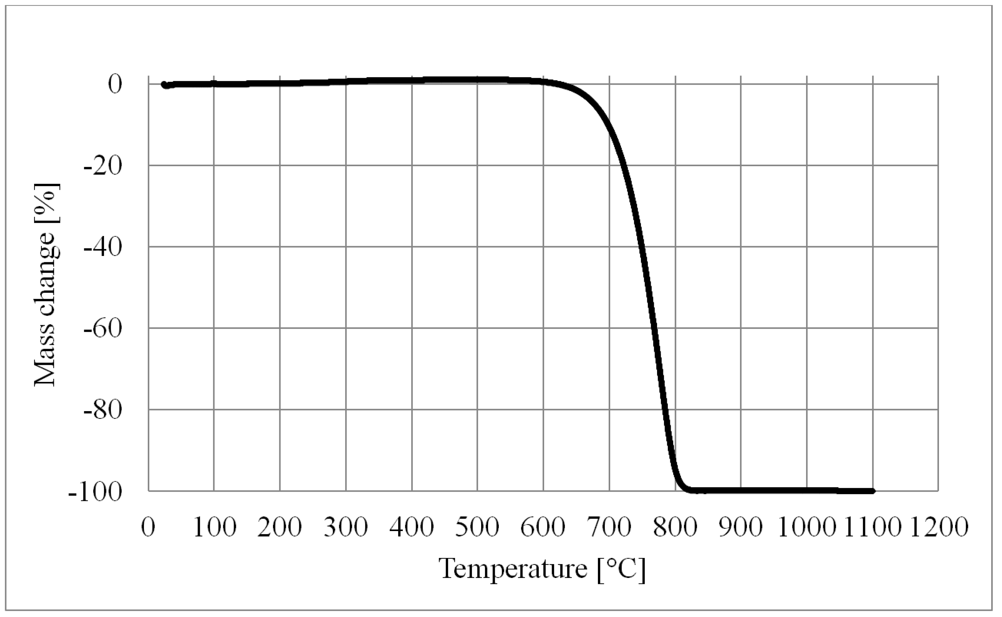
5.1.1. Nickel Oxide Formation

Nickel oxide formation occured from around 300 °C, as can be seen in Figure 3, showing the mass/temperature plot of a thermogravimetric analysis performed using pure Inco 255 nickel powder in air. Increasing recorded mass indicates oxide formation on the powder surface.
Figure 3. Thermogravimetric analysis of pure Inco 255 nickel powder in air.
Energies 08 02337 g003

5.1.2. Burn-off and Reduction

The result of a thermogravimetric analysis with the actual tape casted tape is shown in Figure 4.
Figure 4. Thermogravimetric analysis of tape cast tape burn-off and reduction.
Energies 08 02337 g004
The first 24 h of this TGA temperature program was the burn-off sequence, using synthetic air atmosphere. The sample weight started to decrease rapidly at about 140 °C, indicating burn-off of the organic material in the tape. At about 350 °C the sample weight started increasing, likely due to a very high nickel oxide formation rate. The temperature was maintained at 600 °C for one hour. The sample weight then stabilized, indicating that the high rate of oxide formation had ended. After 24 h the temperature was at room temperature again and the gas flow was changed from synthetic air to a mixture of 5% (vol) H2 + 95% (vol) N2. Heating was started again, and at a temperature of about 350 °C the sample weight started decreasing, indicating that the nickel oxide was being reduced to pure nickel. Above 350 °C the rate of weight loss during reduction was almost constant, even when the temperature was increased up to 600 °C. This indicated that another parameter than temperature was limiting the rate of reduction, most likely the gas diffusion in the sample (pile of tapes) in the crucible, and/or limited molecular transport on/in the surface of the nickel oxide. The efficiency of the burn-off and reduction process could not be measured/quantified, hence the surface was investigated using microscope. No signs of unburned organics or green nickel oxide were found.

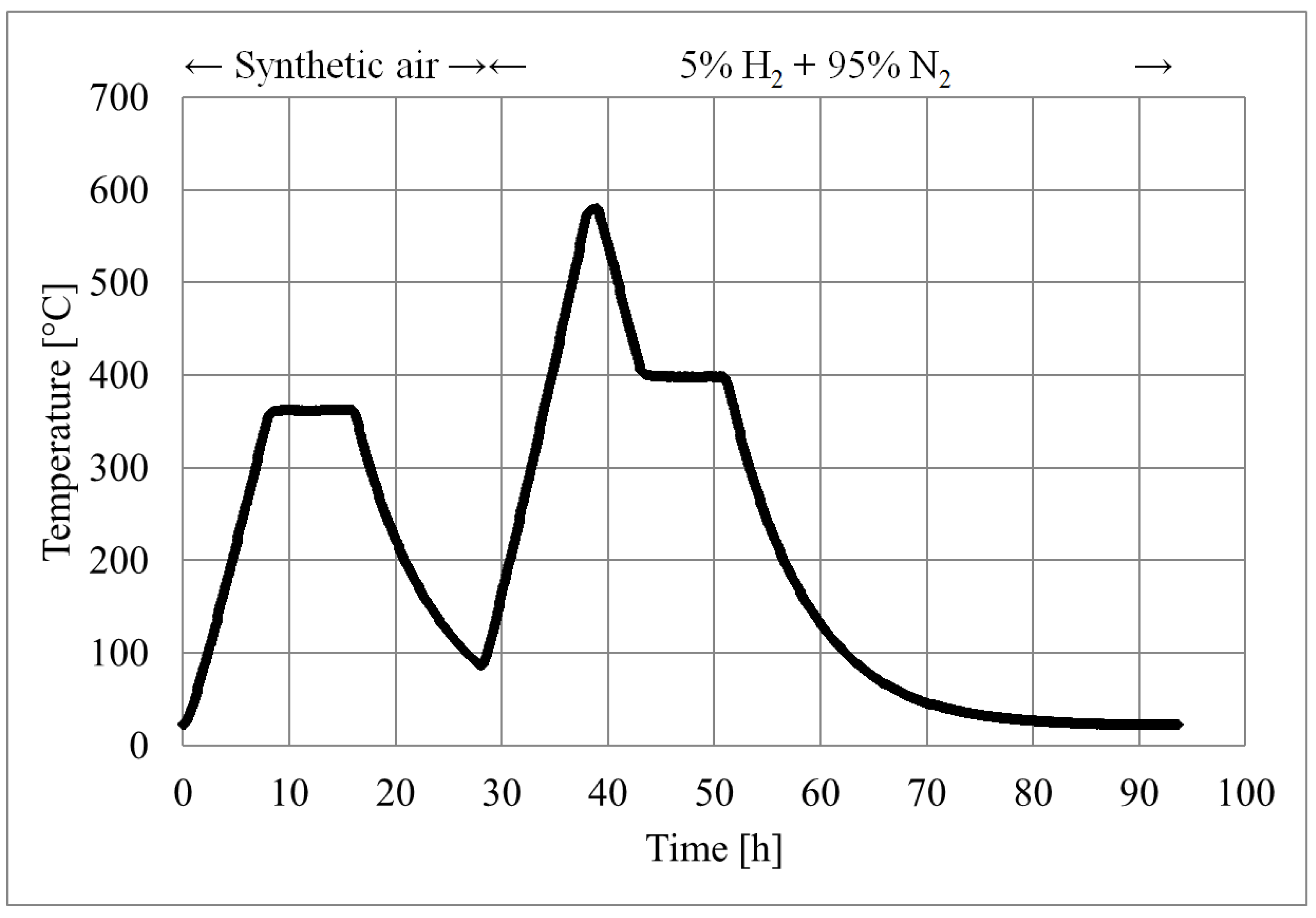
5.1.3. The Temperature Program

The final oven temperature program chosen for the burn-off and sintering process of the real wick is shown in Figure 5. The TGA-data of Figure 4 were utilized in the planning of the process. The requirements were:
  • Sufficient time and temperature for the burn-off.
  • Sufficient time and temperature for proper sintering and acceptable mechanical properties.
  • Sufficient time and temperature for the reduction of the nickel oxide.
In general, too much time and/or too high temperature should be avoided in all parts of the program as this would make the wick unnecessary compact.
The first stage, i.e., the burn-off in synthetic air, was carried out at a maximum level of about 360 °C. The gas composition was changed from synthetic air to a mixture of 5%H2 + 95%N2 after about 29 h. The second stage, i.e., the sintering and reduction, started with a short temperature peak of about 580 °C to ensure proper sintering and mechanical properties of the wick. In order avoid too much compaction of the wick the temperature was then reduced to 400 °C. To ensure sufficient time for the reduction, it was decided to keep the wick for 8 h at about 400 °C.
Figure 5. The temperature in the oven during the burn-off, the sintering and the reduction.
Energies 08 02337 g005
The tape layer structure could be observed after the sintering, but the resulting wick was mechanically strong.

5.1.4. Pure Graphite Powder

The thermogravimetric analysis with the pure graphite powder in air is shown in Figure 6.
The result shows that a burn-off temperature of 800 °C will oxidize all the graphite to CO or CO2 gas.

5.1.5. Tape Containing Pore Former

The thermogravimetric analysis performed for the burn-off in air of a tape casted tape consisting of approximately equal amounts of Inco 255 nickel powder and graphite powder, plus the tape casting additives is shown in Figure 7.
Figure 6. Thermogravimetric analysis with pure graphite powder in air, heating rate 5 K/min.
Energies 08 02337 g006
Figure 7. Thermogravimetric analysis of tape casted tape in air, heating rate 5 K/min.
Energies 08 02337 g007
The weight changes of the sample can be explained as follows: From 150 °C to 400 °C the weight decreased because the tape casting additives were being burnt off. From around 300 °C nickel oxide was formed, causing a weight increase. From around 600 °C the graphite started oxidizing and leaving the sample. Just above 800 °C the weight stabilized, indicating that all the graphite was gone and no more nickel oxide was being formed.

5.2. The Contact Angle

From a series of capillary rise experiments with nickel foam wicks and heptane the contact angle of heptane on nickel was determined to 58.4° [23]. For potassium on nickel a contact angle of 0° was assumed [21].

5.3. Wick Porosity

The porosity measured from three samples of the wick produced by tape casting were ε1 = 0.801, ε2 = 0.79 and ε3 = 0.806, which yielded an average result of ε ≈ 0.80. The applied measurement method ISO 5017 declares that “the values of porosity shall be given to the nearest 0.1% (V/V)” [16]. In the current study the sizes of the samples were smaller than specified by the standard, this could have lead to somewhat larger variations in the results than expected from the standard. The uncertainty is set equal to the measurement variability, i.e., ±0.7%.

5.4. Rate-of-Rise

The height vs time data from the rate-of-rise experiment for the wick produced by tape casting is shown in Figure 8. The height values were calculated numerically from the mass data from the balance, taking the evaporation into account. The evaporation rate from the wick was determined from the experiment. The measured points in Figure 8 are completely covering the “Fit” line generated from the rate-of-rise theory.
Figure 8. Rate-of-rise data for the wick produced by tape casting.
Energies 08 02337 g008
The permeability was determined to 0.108·10−12 m2 and the effective pore radius with heptane to 0.826·10−6 m. From Equation (2) the effective pore radius with potassium then became 0.43 µm. The sensitivity of these values to changes in key variables is discussed in Section 5.6—Sensitivity Analysis. The thermophysical data for heptane and potassium were taken from Faghri [4].

5.5. Prediction of the Wick Maximum Heat Transfer Capacity with Potassium

Static Pressure Limitation

The capacity of the wick made by tape casting, 2.825 mm thick, operated with potassium at 500 °C would according to Equation (8) have been approximately 94 kW/m2 uniform heat flux over the entire surface of 25 × 150 mm. Unfortunately the actual capacity for potassium at 500 °C is much less (only 844 W/m2), due to a heat transfer limitation which has not been given attention in literature: In a heat pipe the capillary pressure can never be higher than the vapour static pressure of the working fluid. For alkali metals, which have very low vapour static pressures, this limitation is of particular interest, especially where large driving pressures are needed, like in long vertical heat pipes with the capillary force working against the gravity. This limitation is termed the “static pressure limit” as it is the vapour static pressure of the working fluid that limits the available driving pressure.
A reduction of the wick height reduces the pressure losses and increases the heat transfer capacity. The tape casted wick could have handled a uniform heat flux of 9069 W/m2 if its height was reduced to 50 mm. An example of how the static pressure limit of the wick appears in a temperature vs. heat flux plot is shown in Figure 9. The plot is for the tape casted wick, 150 mm and 50 mm high, with potassium as working fluid. The capillary pressure is equal to the vapour static pressure at the peaks where the lines representing SPL and CPL intercept. The vapour static pressure of potassium is the limiting pressure for the operation temperatures below the interception point. For temperatures above the interception point the capillary pressure becomes the limiting pressure. For the tape casted wick and using potassium, the interception is obtained at a temperature of about 883 °C. However, this temperature is so high that it would cause sintering of this wick during use.
Figure 9. The theoretical performance of the tape cast wick with potassium working fluid. SPL = Static pressure limited. CPL = Capillary pressure limited.
Energies 08 02337 g009
The exponential form of the SPL curves is caused by the increase in vapour static pressure of the potassium with increasing temperature. The drop in capacity in the CPL region with increasing T is due to the combined effect of the fluid physical properties (viscosity, surface tension, density and latent heat of vapourization).

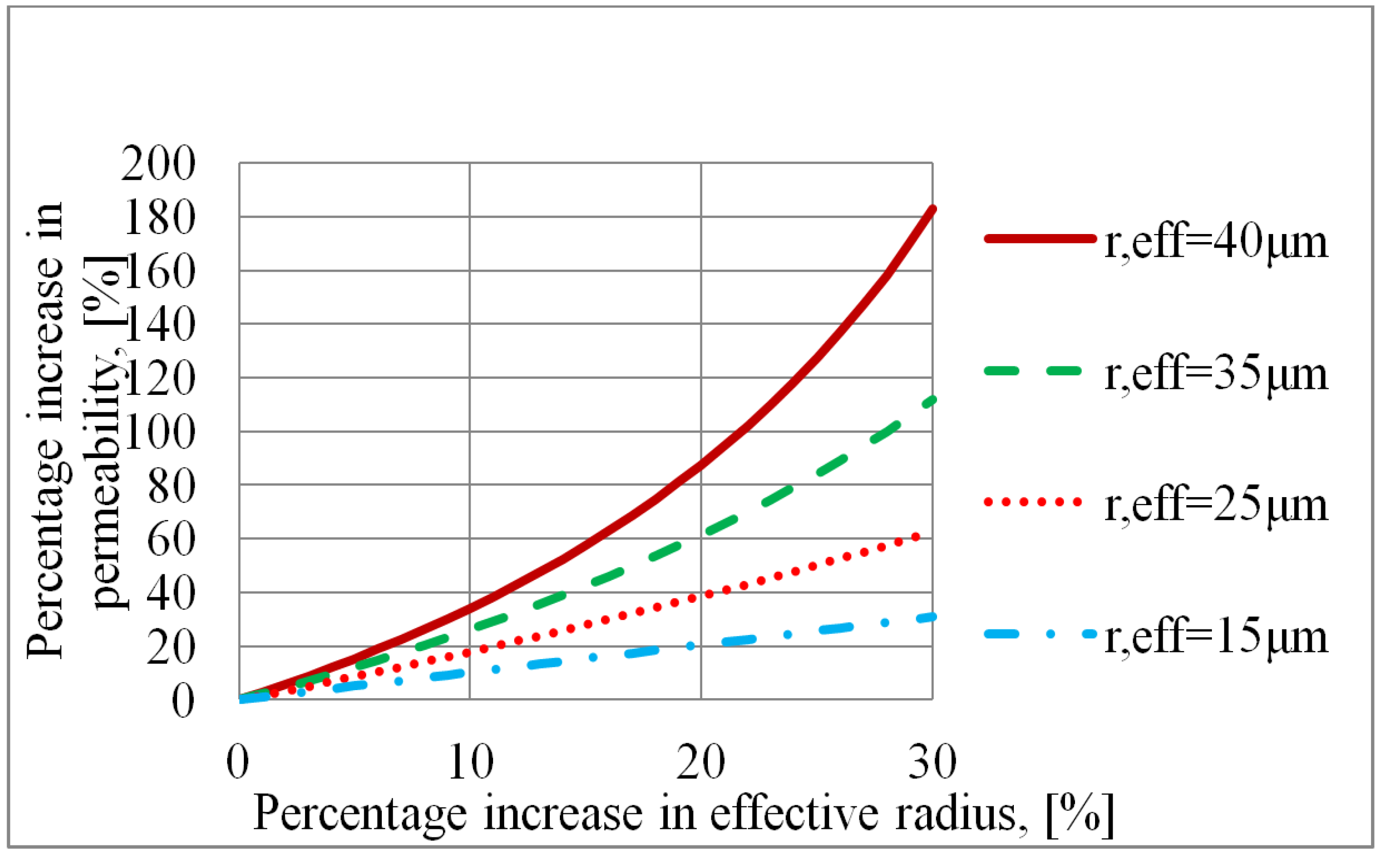
5.6. Sensitivity Analysis

A sensitivity analysis was carried out to see the influence of changes in temperature, porosity, evaporation rate and length measurements on the heat transfer capacity of the wick produced by tape casting. The parameters were varied one by one and the corresponding combinations of effective pore radius and permeability determined. The corresponding heat transfer capacities were calculated by use of Equation (8).

The Influence of Parameter Variations Above and Below Pcap/Psat = 1

It was noticed that small changes in the parameters could cause quite large changes in the effective pore radius and permeability. This finding was also reported by Nam et al. [24] who, in order to overcome the large uncertainties, predicted the permeability by numerical simulations, and used this permeability value together with the rate-of-rise data to determine the effective pore radius. Separate determination of the permeability was also used by Deng et al. [12,25].
Despite of the high sensitivity of (reff, к) to changes in the parameters, the corresponding heat transfer capacities were almost unaffected as long as the capillary pressure was the limiting pressure, indicating that the new sets of effective pore radius and permeability were all on an iso-capacity line. However, the large changes in the permeability propagated to large uncertainties in the calculated capacities for temperatures where the vapour static pressure of the potassium was the limiting pressure, since in this range the large permeability changes were not balanced by corresponding changes in the capillary pressure.
Changes in the heat transfer capacity were calculated for the temperatures 850 °C and 1050 °C to illustrate how changes in the parameters had different impacts above and below Pcap/Psat = 1. The results are presented in Table 1.
Table 1. The heat transfer capacity sensitivity due to parameter changes above and below Pcap/Psat = 1.
ParameterChangeChange in heat transfer capacity at 850 °C (vapour static pressure limited)Change in heat transfer capacity at 1050 °C (capillary pressure limited)
Temperature+1.2 K−28%−0.2%
Porosity+1%−40%−0.9%
Evaporation rate+1%−28%−0.05%
Cross sectional area+1%−47%−6%
The large differences between the sensitivities for the calculated capacities above and below Pcap/Psat = 1 are clearly seen. Plots of the mean absolute deviation (MAD) between the calculated and measured time-height-data did show that there were many pairs of (reff, к) that had near identical MAD. All these different pairs of (reff, к) would give an apparently close to perfect curve fit of the height-time measurements (Figure 8). The calculated sets of (reff, к) for each parameter perturbation in Table 1 varied significantly (as implicitly indicated by the vapour-static-pressure-limited performance sensitivity), but had no significant impact on the capillary-pressure-limited performance. Hence, the rate-of-rise results are useful in the CPL range, even though the individual real values of reff and к are “unknown”. The permeability has to be known with higher certainty for more reliable wick capacity predictions in the temperature range where the vapour static pressure is limiting.

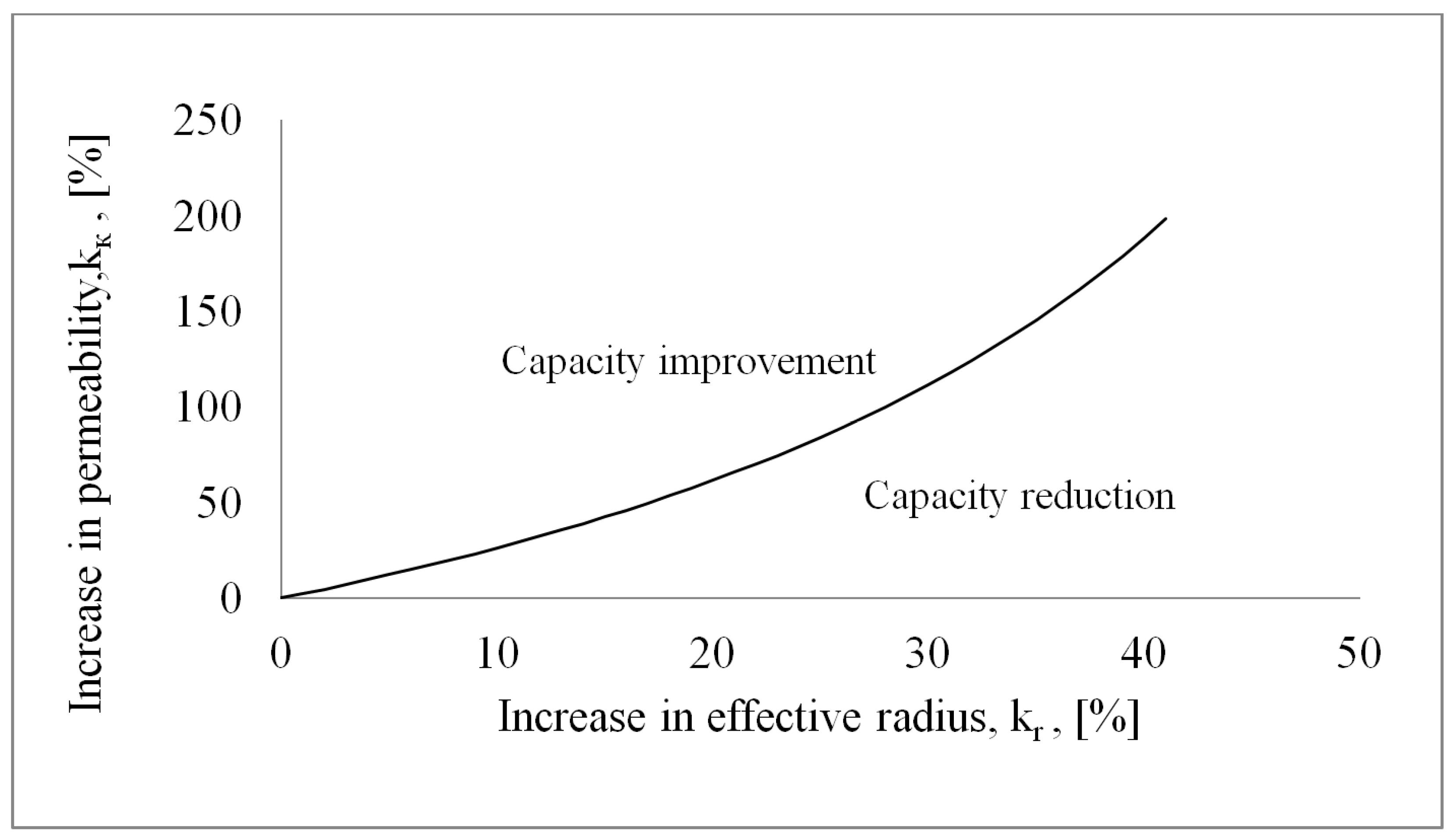
5.7. Criterion for Pore Former Selection

Improved wick performance for potassium/alkali metals would be obtained in both the vapour static pressure limited region and the capillary pressure limited region if the permeability of the wick could be increased without affecting the effective pore radius. However, an increase in the permeability is normally accompanied by an increase in the effective pore radius, and it is therefore necessary to consider the consequences of changes in these parameters together. For wicks made of sintered powder the permeability (and thereby also inevitably the effective pore radius) can be increased by use of a pore former. The permeability and the effective pore radius will generally not experience the same relative change. The consequence for the wick capacity in the vapor static pressure limited region depends on the permeability change, and the consequence in the capillary pressure limited region depends on the relative changes of the permeability and the effective pore radius. The consequence for the wick performance will generally be different in the vapour static pressure limited region and the capillary pressure limited region, because the vapour static pressure is unaffected by changes in the effective pore radius while the capillary pressure is directly a function of the effective pore radius.
In the vapour static pressure limited region the wick performance will always be improved by increased permeability. In order for the pore former to cause general capacity improvement in the capillary pressure limited region, the relative changes in effective pore radius and permeability have to satisfy the criterion for wick capacity improvement by use of pore former, which is derived below.
From Equation (8) it is seen that a proportional increase of the effective pore radius and the permeability actually reduces the wick capacity. Wick improvement requires that the permeability increases more than the effective pore radius, and the exact requirement can be derived from Equation (8). If the increase in effective pore radius is expressed by the factor kr and the increase in permeability is expressed by the factor kк then Equation (8) becomes:
Q ˙ = m ˙ y = 0 h f g = 2 κ k κ A c ρ H μ ( 2 σ r e f f k r ρ g H ) h f g
By combining Equation (11) and Equation (8) the relation between kк and kr appears as:
k κ = 2 σ r e f f ρ g H 2 σ r e f f k r ρ g H
In Figure 10 the factor kк is plotted against the factor kr for different effective pore radii using Equation (12), with H = 0.1 m and properties for heptane at temperature 20 °C.
Figure 10. Pore former evaluation plot for H = 0.1 m and heptane at 20 °C.
Energies 08 02337 g010
The lines in Figure 10 are iso-capacity lines, i.e., the wick capacities are unchanged along the lines. For effective pore radii up to about 15 µm the lines are almost linear, i.e., the capillary term is completely dominating. With increasing effective pore radii the lines become more curved, i.e., in order to maintain the wick capacity the permeability has to increase more than the effective radius. When an iso-capacity line curves upwards the overall effect of a change kr = kк on the wick capacity is negative. The use of a pore former is only successful if it leads to a point above the line, see Figure 11. For instance, in Figure 10, for reff = 35 µm a 20% increase of the effective pore radius has to be accompanied by more than 60% increase of the permeability in order to have an overall heat transfer capacity improvement for the wick.
Figure 11. Pore former evaluation plot.
Energies 08 02337 g011
One way to achieve larger increase in the permeability than in the effective pore radius may be to use a pore former consisting of long filaments, creating longitudinal channels in the sintered metal powder. A potential candidate is using carbon fibers arranged in the wick flow direction.

6. Conclusions

  • The capillary pressure inside a heat pipe can never exceed the vapour static pressure of the working fluid. This will limit the heat transfer capacity and the useful operating temperature range for heat pipes with wicks with small effective pore radii operated with working fluids with low vapour static pressures, for instance alkali metals.
  • Determination of the effective pore radius and the permeability from a rate-of-rise experiment alone can lead to great uncertainties about the actual values. Many different pairs of (reff, к) give good curve fits, and in such case they can all be used for approximate wick capacity predictions for (Pcap/Psat < 1). For wick capacity predictions for (Pcap/Psat > 1) the permeability has to be known with higher accuracy.
  • In the vapour static pressure limited region the use of a pore former which increases the wick permeability will always improve the wick performance.
  • In the capillary pressure limited region, a pore former evaluation plot may be made in order to analyse the effects of using a pore former. If the effective radius and permeability increase with an equal percentage the overall effect on the wick heat transfer capacity is negative. A pore former which increases the permeability more than the effective pore radius would be a better choice than a powderous pore former. One such candidate can be carbon fibers.
  • The oxidation of Inco 255 nickel powder accellerates at about 350 °C.
  • The reduction of nickel oxide in 5%H2 + 95%N2 accellerates at about 350 °C.
  • In order to burn off a graphite powder pore former a temperature of about 800 °C is required.

Acknowledgments

The authors would like to thank Elkem and the Research Council of Norway for funding this work. Thanks to Mr. Rhodri Bowen of Vale Inco Europe Ltd for supplying Inco 255 nickel powder. Thanks to Dr. Vegar Øygarden for assistance on pure nickel powder TGA and to Dr. Ove Paulsen for valuable and inspiring talks on sintering.

Author Contributions

Geir Hansen carried out the experimental work, data reduction, and prepared the first draft of the paper. The MatLab™-code for the rate-of-rise analysis and the pore former success criterion were made by Kolbeinn Kristjansson. Geir Hansen and Erling Næss have equally contributed on the analysis and paper preparation.

Symbols

Ac
wick cross sectional area, m2
C
constant
E
Deviation
g
gravity constant, g = 9.81 m/s2
H
height, m
hfg
latent heat of evaporation, kJ/kg
kк
factor expressing change in permeability
kr
factor expressing change in radius
m ˙
mass flow rate, kg/s
P
pressure, Pa
Q ˙
heat flow rate, W
r
radius, m
reff
effective radius, m
t
time, s
V
volume
V ˙
velocity, m/s
y
height, m

Greek symbols

Г
evaporation rate per unit height of wetted wick, kg/(m·s)
ε
porosity
θ
solid-liquid-vapour contact angle, degrees
к
permeability, m2
µ
dynamic viscosity, kg/(m·s)
ρ
density, kg/m3
σ
surface tension, N/m

Subscripts

cap
capillary
eff
effective (pore radius)
f
friction
g
gravity
l
liquid
sat
saturated
v
vapour

Conflicts of Interest

The authors declare no conflict of interest.

References

  1. Reay, D.A.; Kew, P.A.; Dunn, P.D. Heat Pipes; Elsevier: Amsterdam, The Netherlands, 2006. [Google Scholar]
  2. Çengel, Y.A. Heat and Mass Transfer: A Practical Approach; McGraw-Hill: Boston, MA, USA, 2007. [Google Scholar]
  3. De Schampheleire, S.; De Kerpel, K.; Deruyter, T.; De Jaeger, P.; De Paepe, M. Experimental study of small diameter fibres as wick material for capillary-driven heat pipes. Appl. Therm. Eng. 2015, 78, 258–267. [Google Scholar] [CrossRef]
  4. Faghri, A. Heat Pipe Science and Technology; Taylor & Francis: Washington, DC, USA, 1995. [Google Scholar]
  5. Franchi, G.; Huang, X. Development of composite wicks for heat pipe performance enhancement. Heat Transf. Eng. 2008, 29, 873–884. [Google Scholar] [CrossRef]
  6. Huang, X.; Franchi, G. Design and fabrication of hybrid bi-modal wick structure for heat pipe application. J. Porous Mat. 2008, 15, 635–642. [Google Scholar] [CrossRef]
  7. Huang, X.; Franchi, G.; Cai, F. Characterization of porous bi-modal ni structures. J. Porous Mat. 2009, 16, 165–173. [Google Scholar] [CrossRef]
  8. Li, J.; Zou, Y.; Cheng, L.; Singh, R.; Akbarzadeh, A. Effect of fabricating parameters on properties of sintered porous wicks for loop heat pipe. Powder Technol. 2010, 204, 241–248. [Google Scholar] [CrossRef]
  9. Kim, H.J.; Lee, S.-H.; Kong, Y.C.; Jang, S.P.; Choi, J.H.; Koo, J. Long-term reliability of the thermal performance of a flat-plate heat pipe using a prognostics method. Int. J. Heat Mass Transf. 2015, 82, 369–372. [Google Scholar] [CrossRef]
  10. Sheehan, J.; Queheillalt, D.T.; Norris, P.M. An evaluation of the wicking characteristics of stochastic open-cell nickel foams. In Proceedings of the 2006 ASME International Mechanical Engineering Congress and Exposition, IMECE2006, Chicago, IL, USA, 5–10 November 2006.
  11. Shirazy, M.R.S.; Blais, S.; Frechette, L.G. Mechanism of wettability transition in copper metal foams: From superhydrophilic to hydrophobic. Appl. Surf. Sci. 2012, 258, 6416–6424. [Google Scholar] [CrossRef]
  12. Deng, D.; Liang, D.; Tang, Y.; Peng, J.; Han, X.; Pan, M. Evaluation of capillary performance of sintered porous wicks for loop heat pipe. Exp. Therm. Fluid Sci. 2013, 50, 1–9. [Google Scholar] [CrossRef]
  13. Holley, B.; Faghri, A. Permeability and effective pore radius measurements for heat pipe and fuel cell applications. Appl. Therm. Eng. 2006, 26, 448–462. [Google Scholar] [CrossRef]
  14. Tracey, V.A. Sintering data for inco nickel powder type 255. In Technical Note; INCO: New York, NY, USA, 1979. [Google Scholar]
  15. Mistler, R.E.; Twiname, E.R. Tape Casting Theory and Practice; The Amercan Ceramic Society: Westerville, OH, USA, 2000. [Google Scholar]
  16. Dense Shaped Refractory Products—Determination of Bulk Density, Apparent Porosity and True Porosity; International Organization for Standardization: Geneva, Switzerland, 1998.
  17. Adkins, D.R.; Dykhuizen, R.C. Procedures for measuring the properties of heat-pipe wick materials. In Proceedings of the 28th Intersociety Energy Conversion Engineering Conference, Atlanta, GA, USA, 8–13 November 1993; American Chemical Society: Washington, DC, USA, 1993; Volume 2, pp. 911–917. [Google Scholar]
  18. Shirazy, M.R.S.; Frechette, L.G. Investigation of capillary properties of copper metal foams by the rate of rise method in the presence of evaporation. In Proceedings of the 13th InterSociety Conference on Thermal and Thermomechanical Phenomena in Electronic Systems, ITherm 2012, San Diego, CA, USA, 30 May–1 June 2012; IEEE Computer Society: San Diego, CA; USA, 2012; pp. 710–716. [Google Scholar]
  19. Hiemenz, P.C. Principles of Colloid and Surface Chemistry; Dekker: New York, NY, USA, 1986. [Google Scholar]
  20. Dwyer, O.E. Boiling Liquid-Metal Heat Transfer, 1st ed.; American Nuclear Society: Hinsdale, IL, USA, 1976. [Google Scholar]
  21. Barlow, M.; Planting, P.J. Wetting of metal surfaces by liquid alkali metals. Z. Metallk. 1969, 60, 719–722. [Google Scholar]
  22. Reay, D.A.; Kew, P.A.; McGlen, R.; Dunn, P.D. Heat Pipes: Theory, Design, and Applications; Butterworth-Heinemann, an imprint of Elsevier: Kidlington, Oxford, UK, 2014. [Google Scholar]
  23. Hansen, G.; Næss, E. Performance of compressed nickel foam wicks for flat vertical heat pipes. Appl. Therm. Eng. 2015, 81, 359–367. [Google Scholar] [CrossRef]
  24. Nam, Y.; Sharratt, S.; Byon, C.; Sung Jin, K.; Ju, Y.S. Fabrication and characterization of the capillary performance of superhydrophilic cu micropost arrays. J. Microelectromech. Syst. 2010, 19, 581–588. [Google Scholar] [CrossRef]
  25. Deng, D.; Tang, Y.; Huang, G.; Lu, L.; Yuan, D. Characterization of capillary performance of composite wicks for two-phase heat transfer devices. Int. J. Heat Mass Transf. 2013, 56, 283–293. [Google Scholar] [CrossRef]

