
Stable Operation and Electricity Generating Characteristics of a Single-Cylinder Free Piston Engine Linear Generator: Simulation and Experiments


Abstract
:1. Introduction
2. Simulation Modelling and Methodology
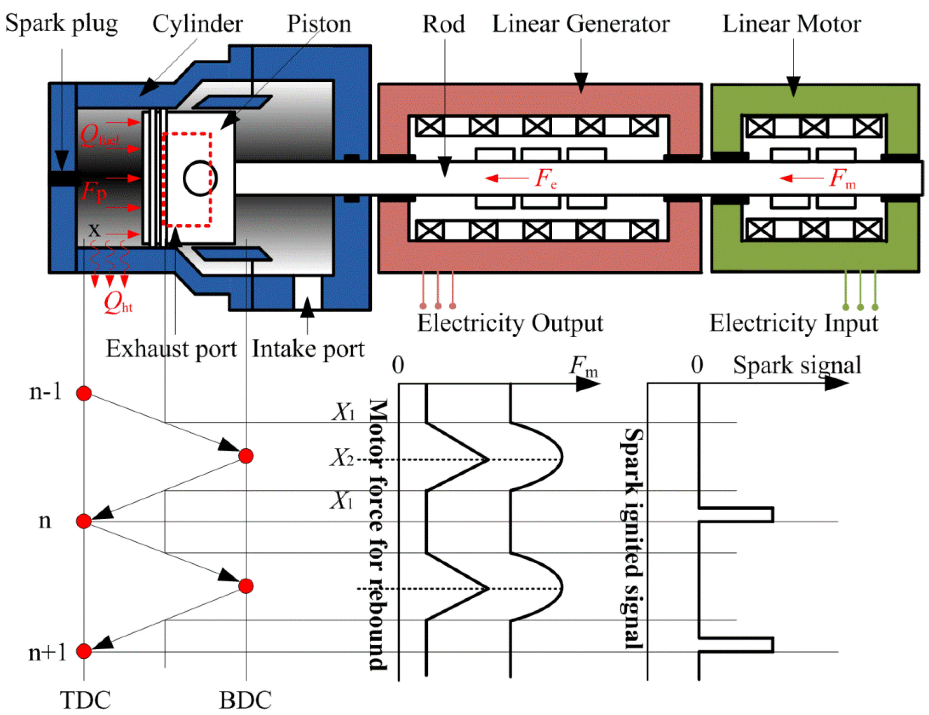
2.1. Linear Motor Force Profiles
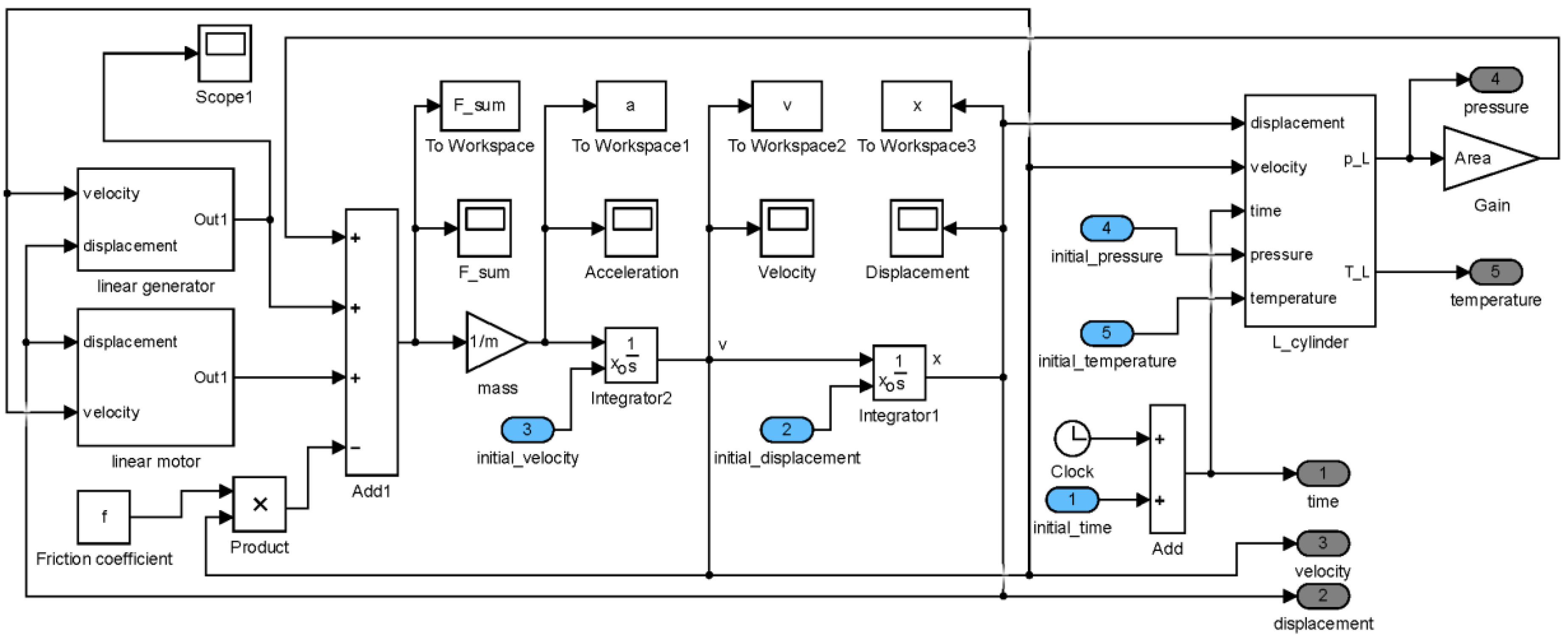
2.2. Simulation Model
2.2.1. Dynamic Modeling
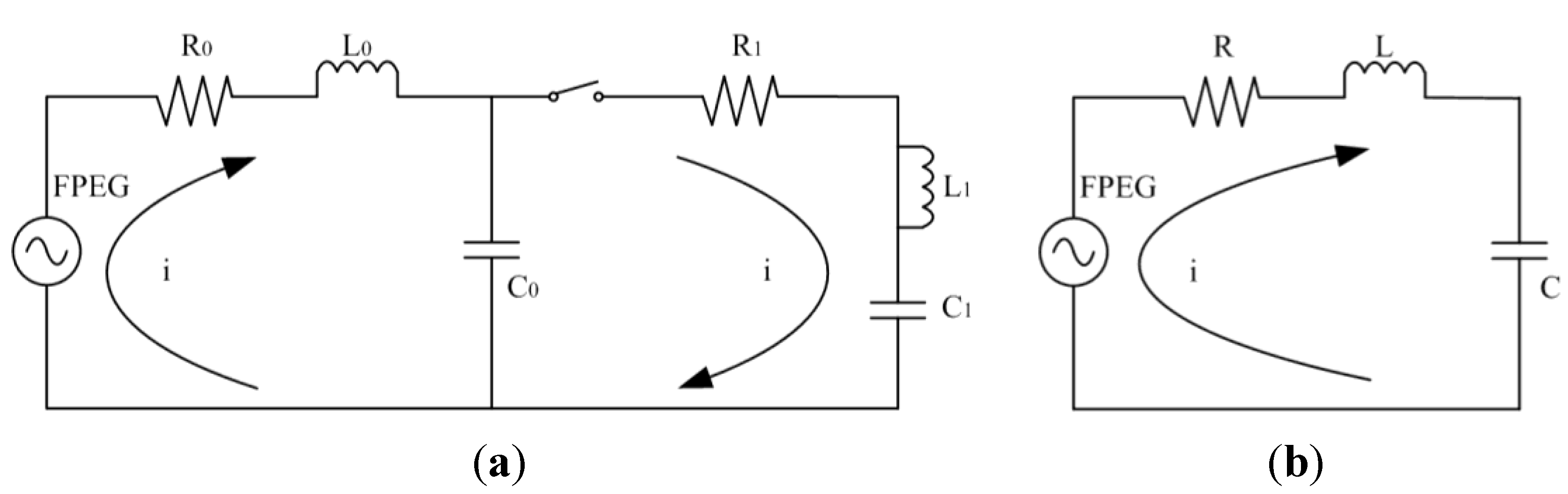
2.2.2. Linear Generator Modeling
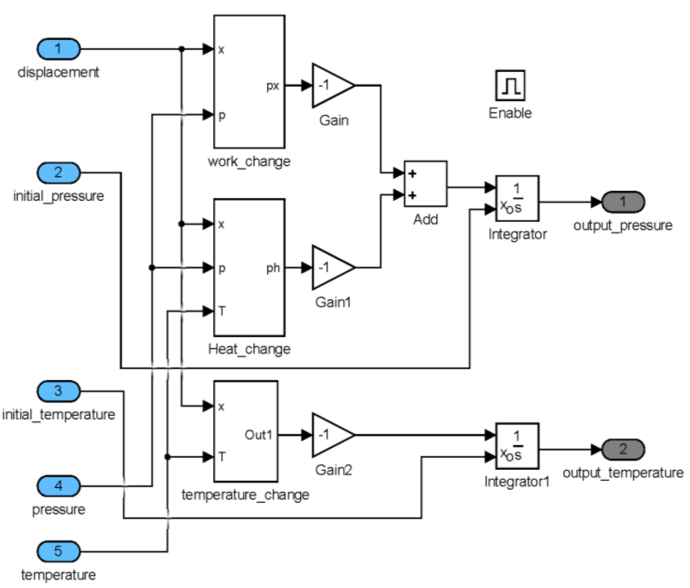
2.2.3. Thermodynamic Modelling
2.2.4. Frictional Modelling
2.3. Simulation Method

| Parameters | Value |
|---|---|
| Bore | 34.0 mm |
| Piston assembly mass | 5.0 kg |
| Spark ignited position | 3.0 mm |
| Intake port open position | 28.0 mm |
| Exhaust port open position | 25.0 mm |
| Initial pressure in cylinder | 1.013 × 10⁵ Pa |
| Load constant | 100 Ns/m |
| Design stroke | 45 mm |
| Parameters | Value |
|---|---|
| Combustion duration | 4.5 ms |
| Combustion quality factor | 2 |
| Average velocity y of piston | 3 m/s |
| Specific heat ratio in compression stroke | 1.33 |
| Specific heat ratio in expansion stroke | 1.30 |
| Lower heating value of fuel | 4.4 × 10⁷ J/kg |


2.4. Simulation Results and Discussion
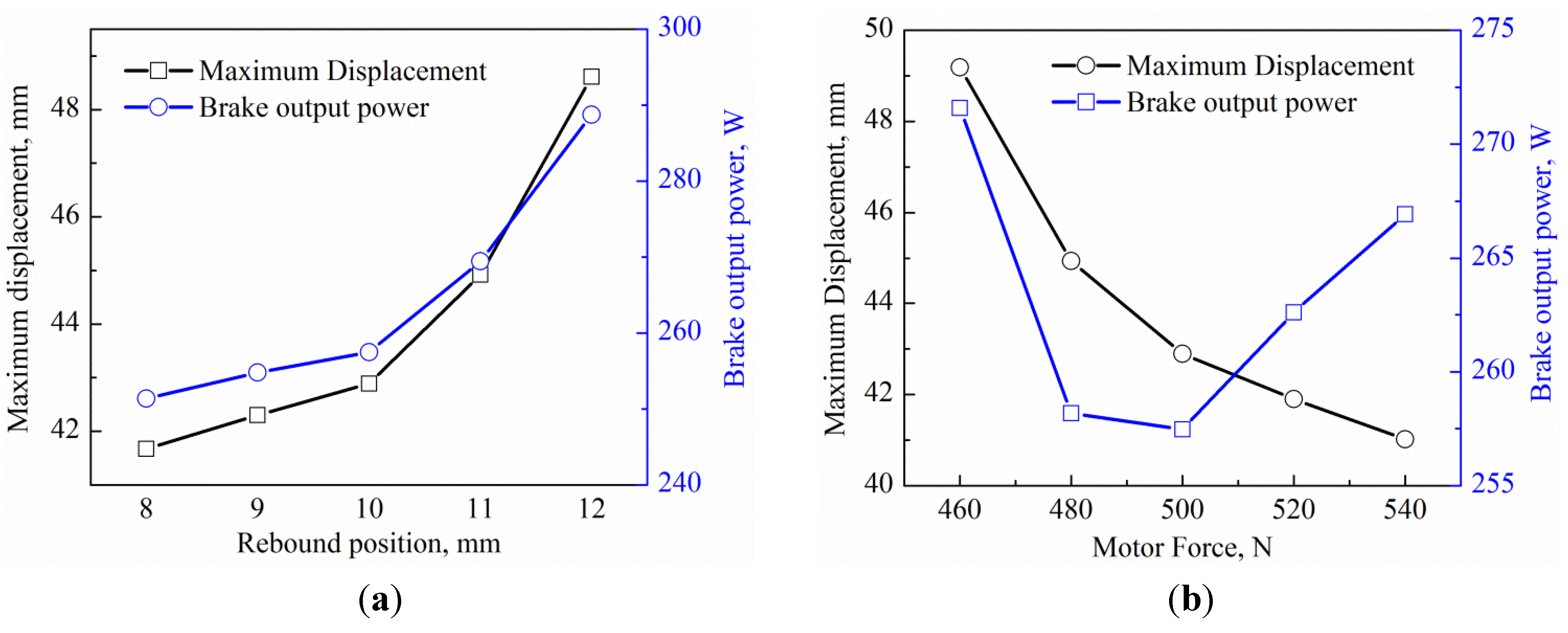
2.4.1. Different Motor rebound Forces and Positions
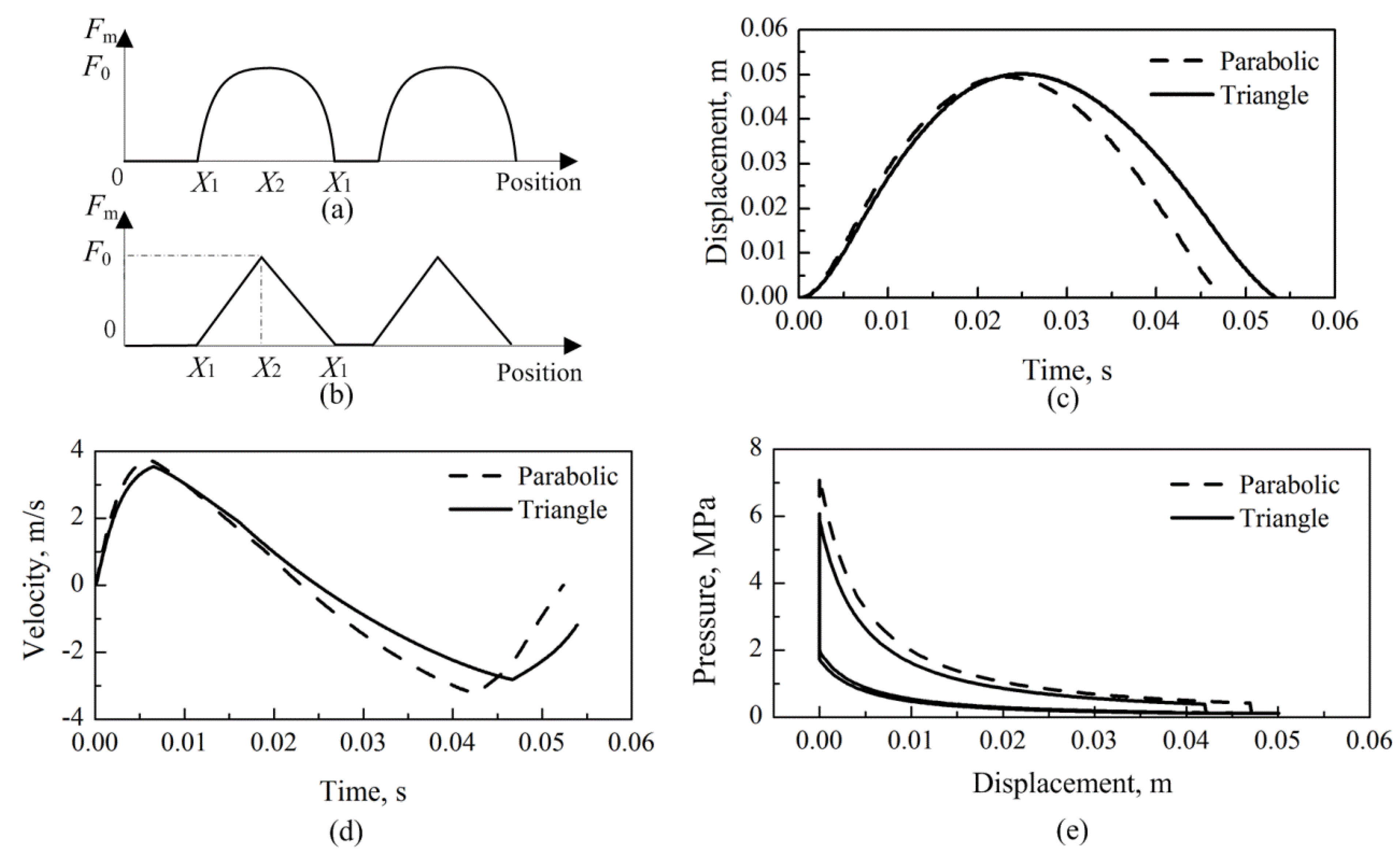
2.4.2. Different Motor Force Types
3. Electricity Generating Characteristics of the Linear Generator
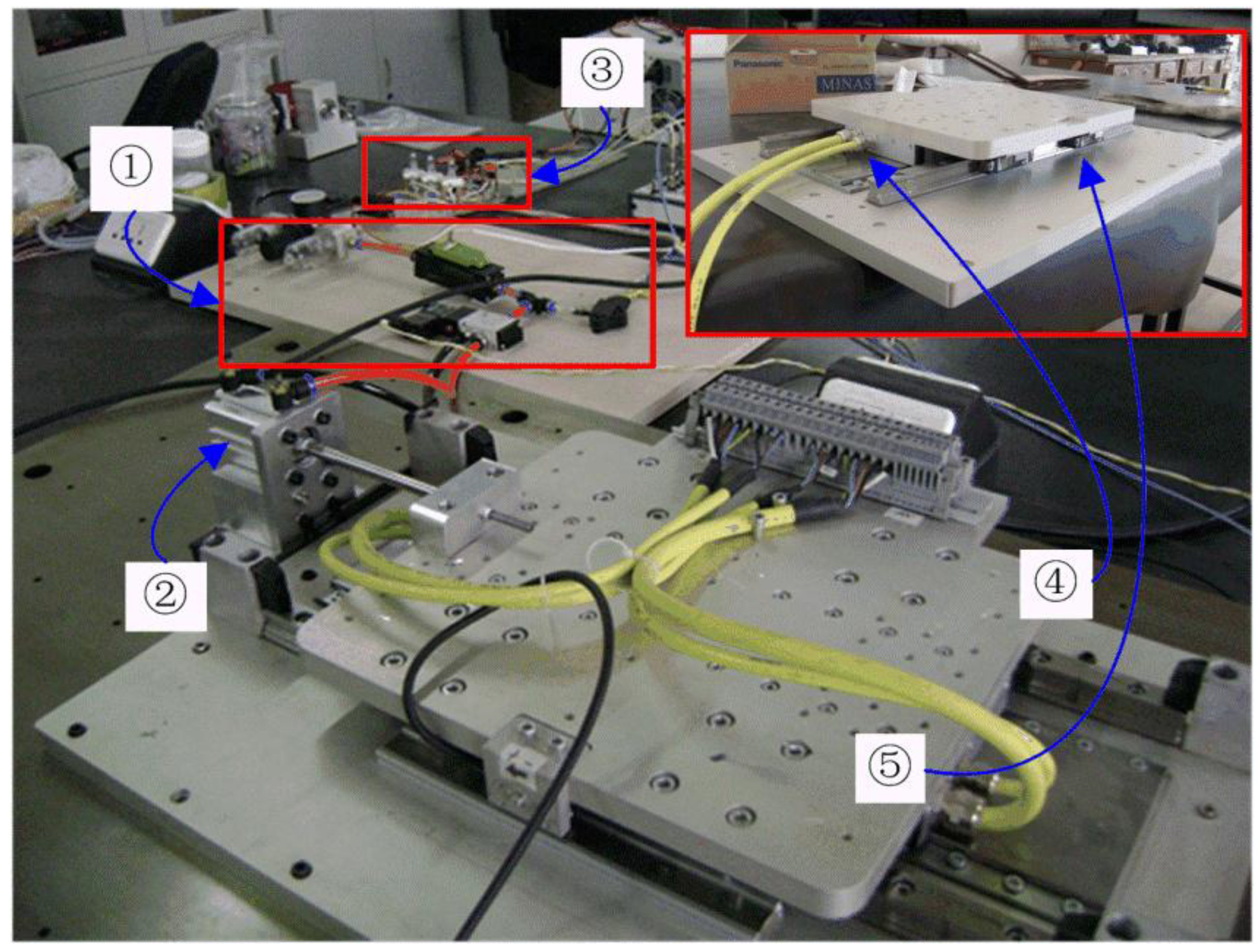
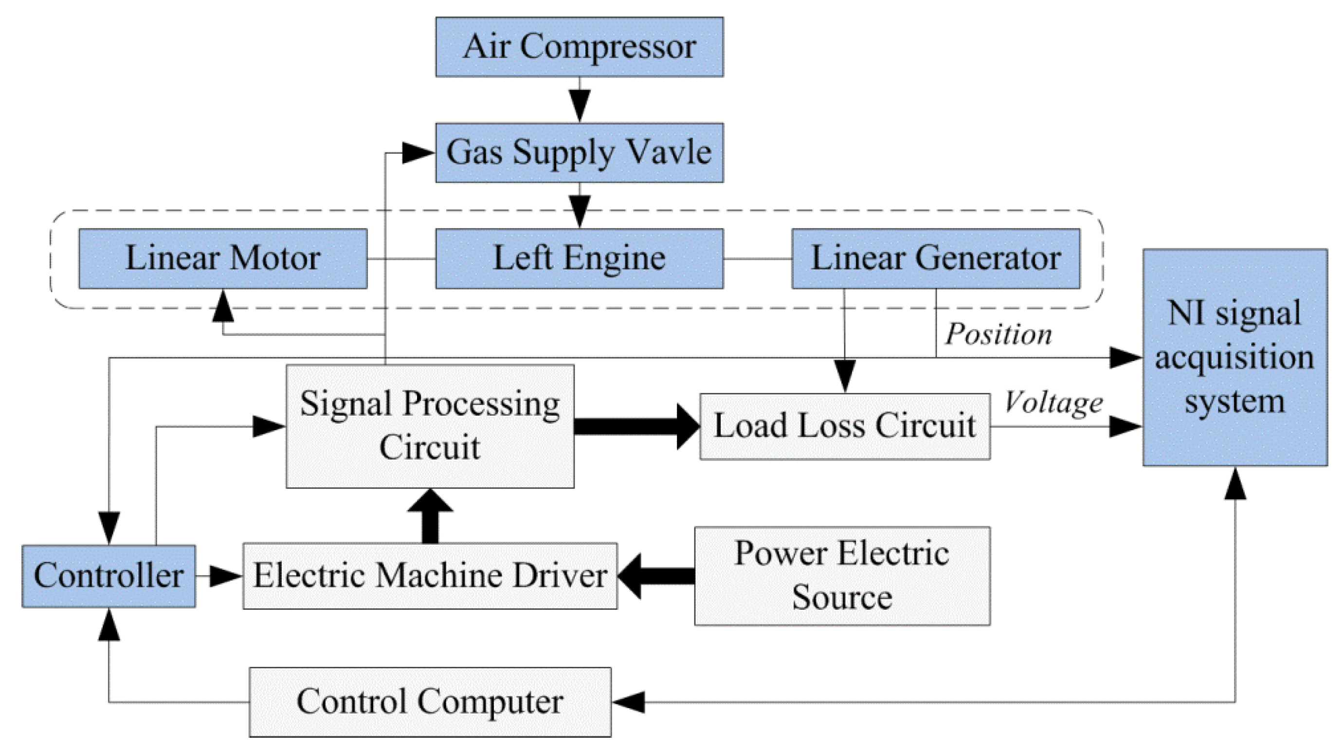
3.1. FPELG Prototype
| Parameters | Linear Motor/Generator |
|---|---|
| Maximum stroke | 180 mm |
| Actual stroke | 50 mm |
| Width of air gap | 7.2 mm |
| Width of the permanent magnet | 12 mm |
| Turns per coil | 180 |
| Mass of permanent magnet | 1.6 kg |
| Peak force | 1300 N |
| Force constant (25 °C) | 44.7 N/A |
| Continuous stall force | 440 N |
| Peak current | 41.5 A |
| Back EMF constant (ph-ph, °C) | 25.8 V/(m·s−1) |
| Resistance | 12 s |
| Peak velocity | 19.2 m·s−1 |
| Test Device | Accuracy |
|---|---|
| Linear generator | 0.01 mm |
| Electric machine controller | 0.01 mm |
| Electric machine driver | 0.01 mm |
| Linear displacement transducer | 0.1% |
3.2. Test Results
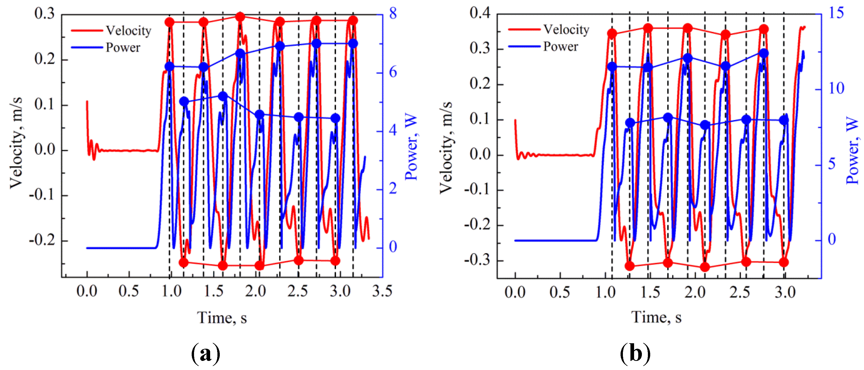
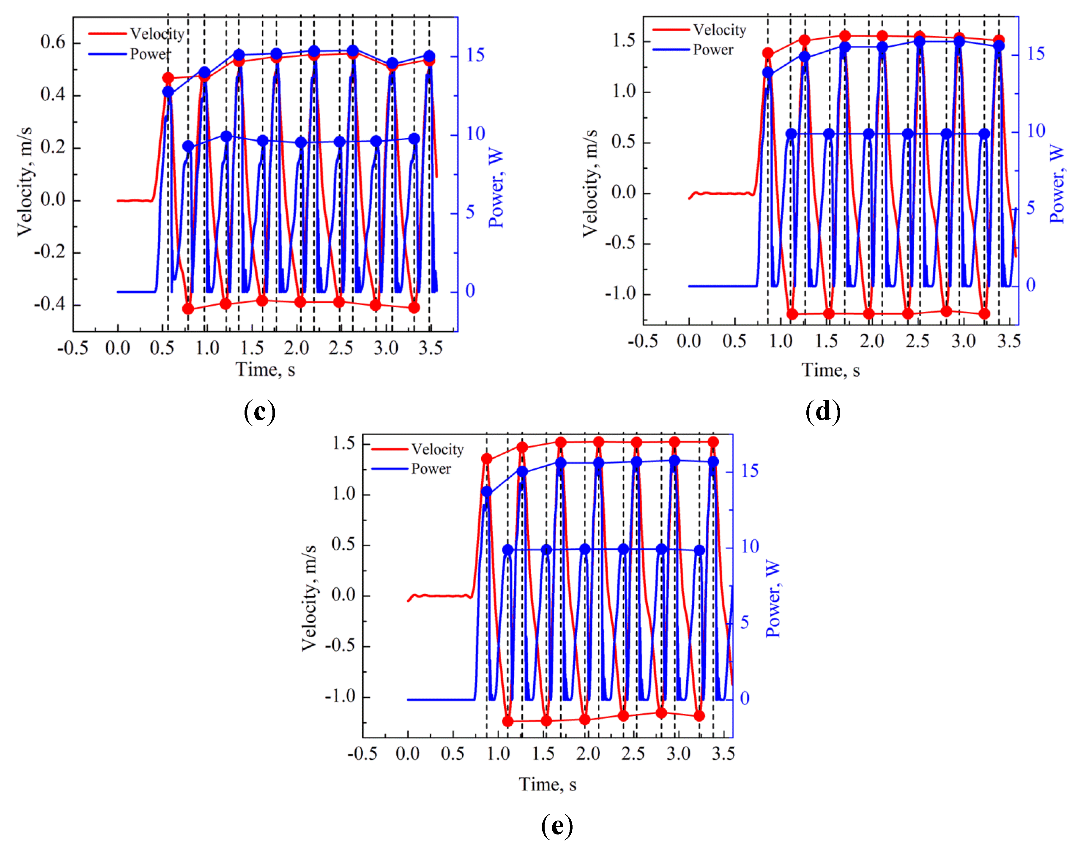
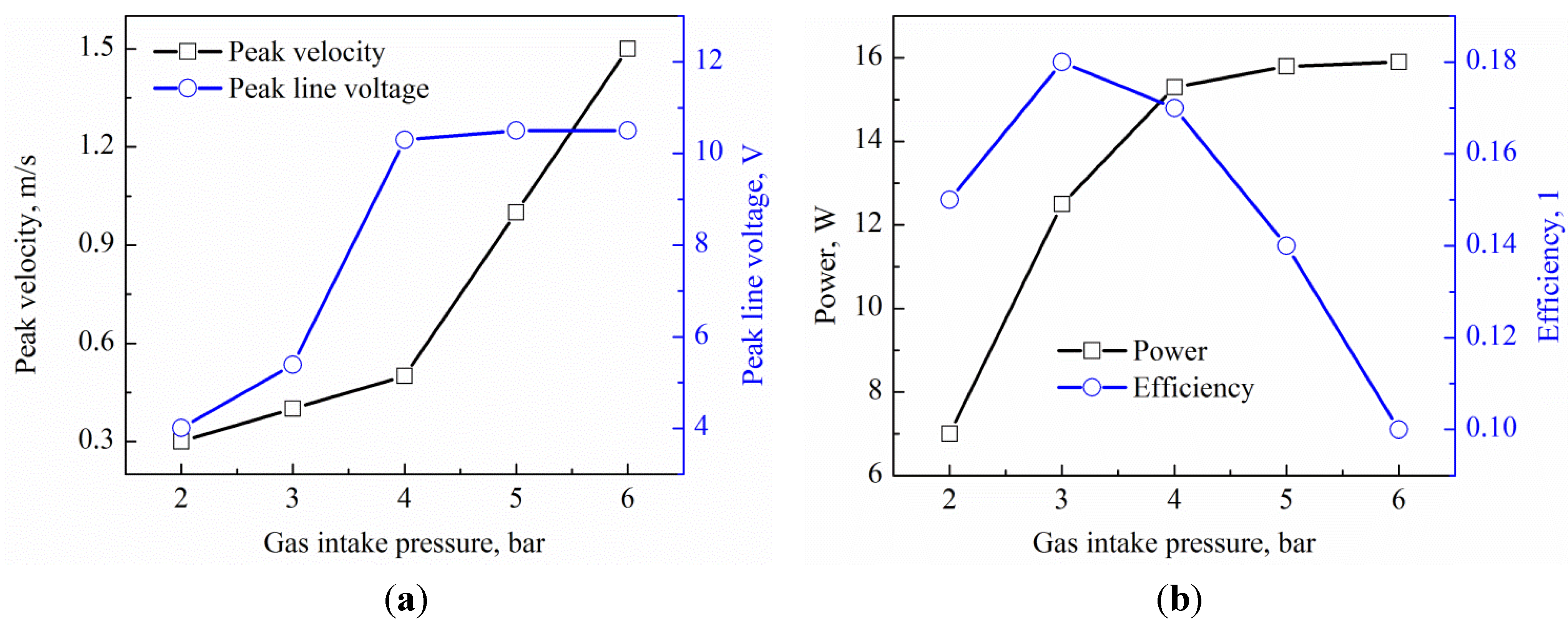
3.2.1. Variation of Intake Pressures


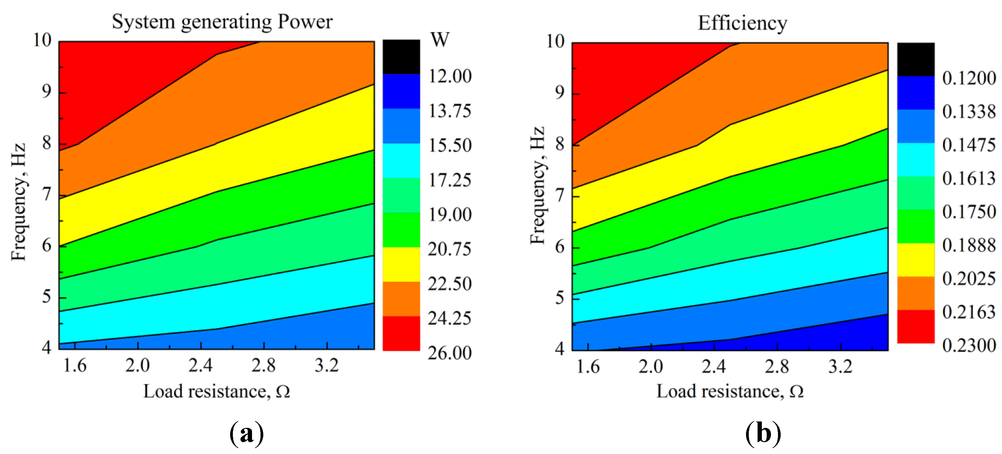
3.2.2. Variation of Frequency
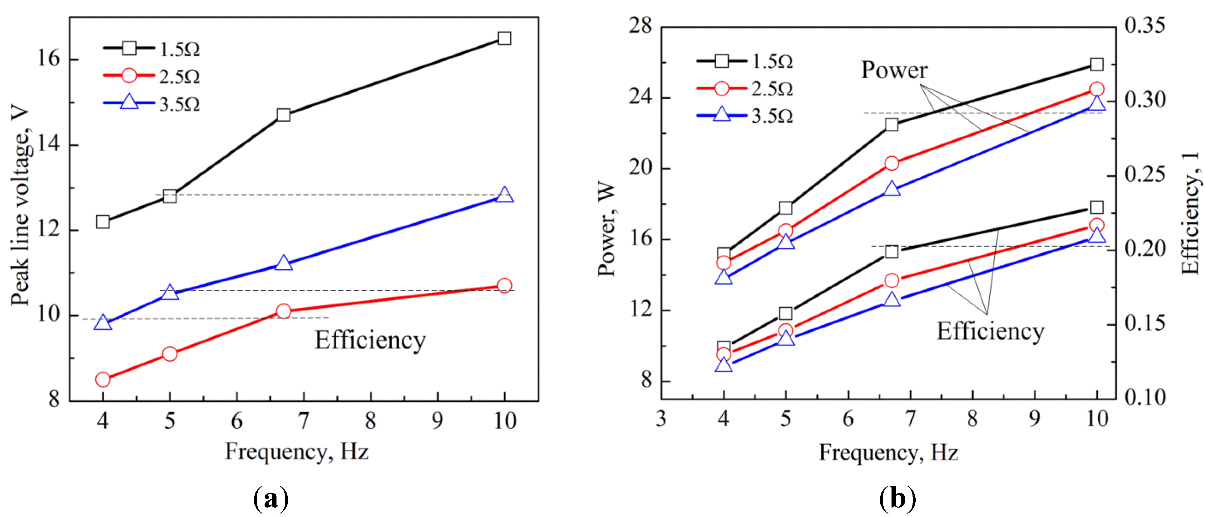

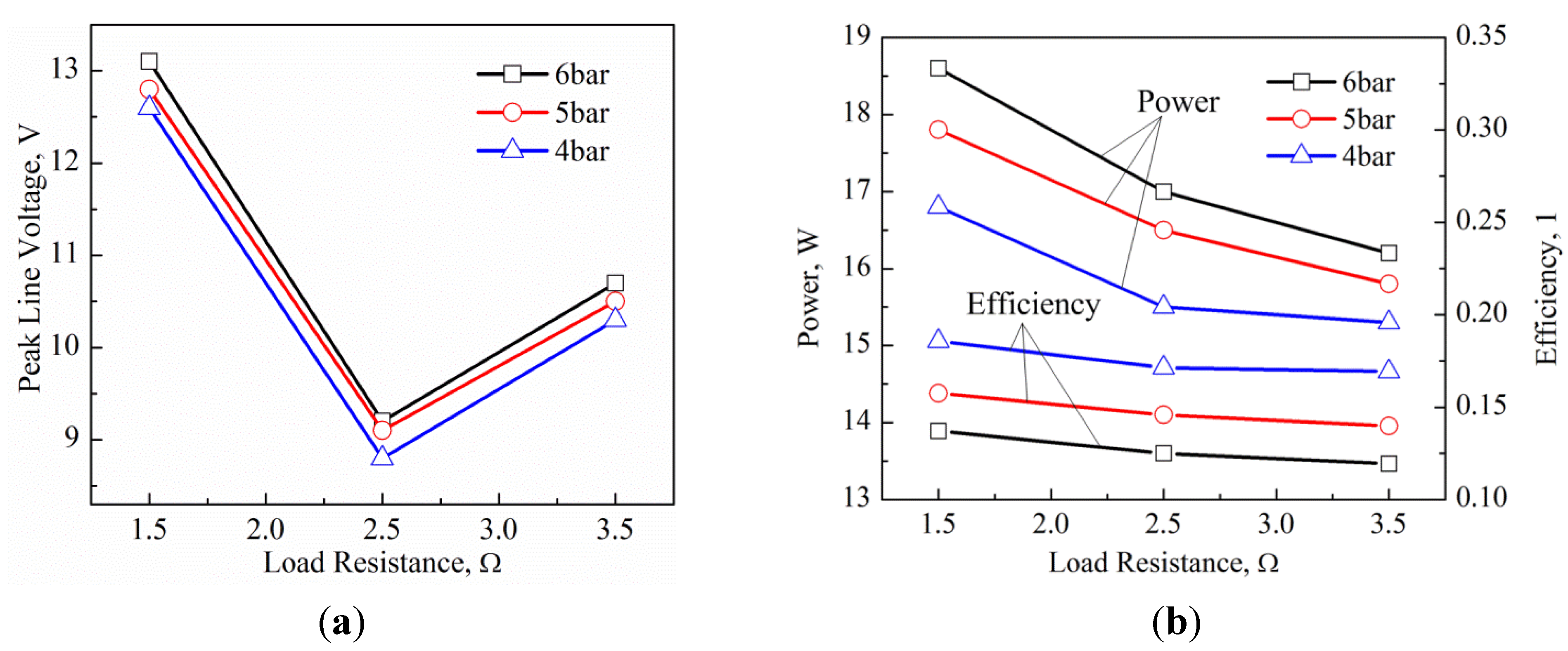
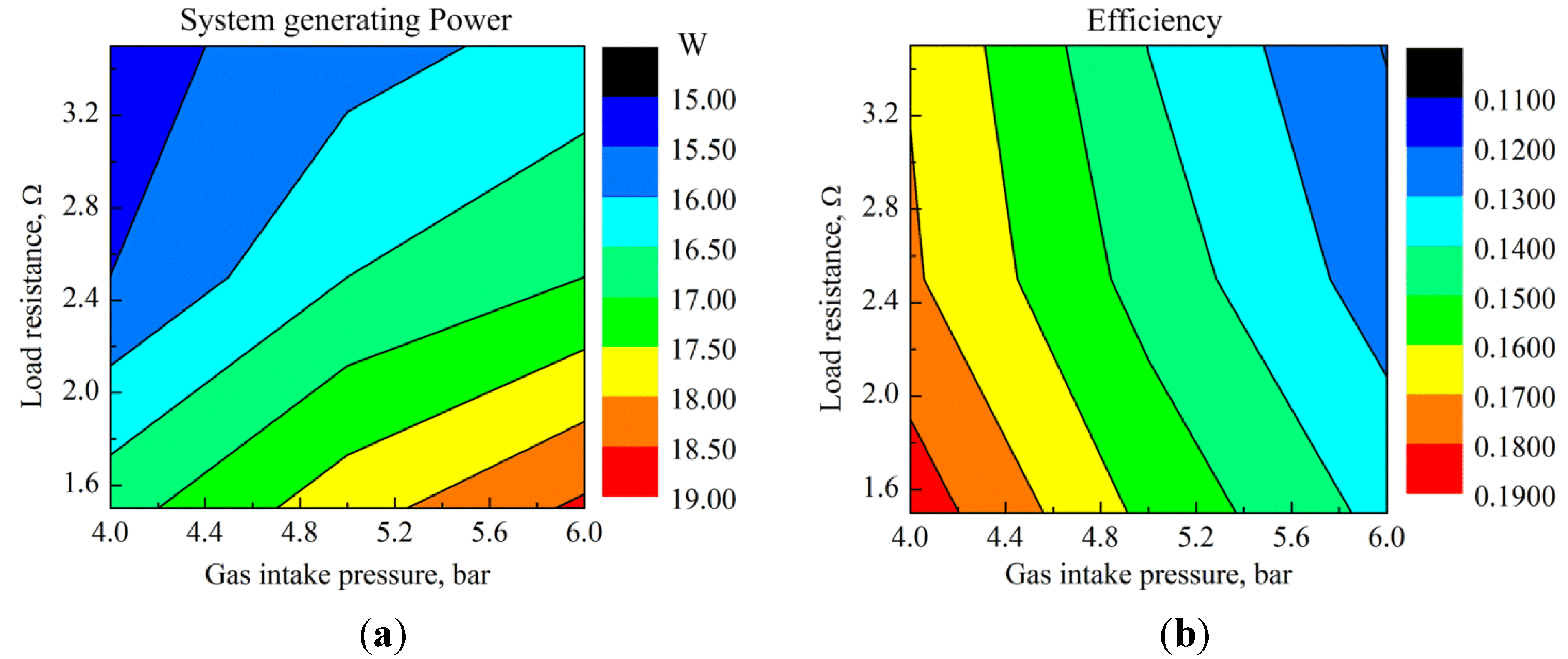
3.2.3. Variation of Load Resistance


4. Conclusions
- (1)
- In the simulation, the peak value of displacement increases with the increase of motor rebound force. There is a minimal value of brake output power when the motor rebound force is approximately 500 N. When the motor rebound position increases, the maximum displacement and brake output power of the linear generator both increase.
- (2)
- Compared to a motor rebound force with a triangular profile, a parabolic motor rebound force profile has advantages such as higher values of the maximum positive velocity, shorter time to reach the TDC, and higher peak cylinder pressure.
- (3)
- Experimentally, the maximum velocities and peak output power were not stable after the starting process until the intake pressure reached 4 bar. As the gas intake pressure increased, the system output power rose continually. However, the system reached its maximum efficiency before reaching maximum output power, which rose slowly.
- (4)
- The parameters of frequency and load resistance could be adjusted to achieve a special peak line voltage, peak power, and efficiency, which is one of the ways to control the system. The output power reached 25.9 W and the system efficiency reached 13.7%.
Nomenclature
Abbreviations
| BDC | Bottom dead center |
| TDC | Top dead center |
Symbols
| Fp | Combustion-gas pressure [N] |
| Ff | Frictional force [N] |
| Fm | Motor force [N] |
| Fe | Electromagnetic force [N] |
| F0 | Maximum motor force [N] |
| R | Resistance [Ω] |
| L | Inductance [H] |
| Φ | Coil magnetic flux |
| eg | Induced electromotive force [V] |
| c | Constant of load |
| X1 | Rebound position [mm] |
| X2 | Bottom dead center position [mm] |
| S | Maximum displacement [m] |
| P | Brake output power [w] |
| m | Piston assembly mass [kg] |
| Qht | Heat transfer at cylinder [J] |
| h | Heat transfer coefficient |
| Ū | Mean piston speed [m/s] |
| x(t) | Fuel mass fraction burned [%] |
| t | Time [s] |
| ma | The sum of the gas [kg] |
| mi | The gas mass of i constitutent [kg] |
| U | Internal energy [J] |
| u | Specific heat |
| p | Pressure in cylinder [MPa] |
| V | Gas volume in cylinder [m3] |
| R | The gas constant [J/kg K] |
| T | Gas temperature [K] |
| Tw | Wall temperature [K] |
| Q | Total input energy [J] |
| cv | The specific heat capacity at constant volume [J/kg K] |
| γ | Specific heat ratio |
| Qc | Heat released in combustion [J] |
| a、b | Shaping factors |
| t0 | The time combustion begins [s] |
| tc | The combustion duration [s] |
| fmep | Mean frictional pressure [Pa] |
Acknowledgments
Author Contributions
Conflicts of Interest
References
- Mikalsen, R.; Roskilly, A.P. Performance simulation of a spark ignited free-piston engine generator. Appl. Ther. Eng. 2008, 28, 1726–1733. [Google Scholar] [CrossRef]
- Mao, J.; Zuo, Z.; Feng, H. Parameters coupling designation of diesel free-piston linear alternator. Appl. Energy 2011, 88, 4577–4589. [Google Scholar] [CrossRef]
- Mikalsen, R.; Roskilly, A.P. A review of free-piston engine history and applications. Appl. Therm. Eng. 2007, 27, 2339–2352. [Google Scholar] [CrossRef]
- Mikalsen, R.; Jones, E.; Roskilly, A.P. Predictive piston motion control in a free-piston internal combustion engine. Appl. Energy 2010, 87, 1722–1728. [Google Scholar] [CrossRef]
- Mao, J.; Zuo, Z.; Liu, D. Numerical Simulation of a Spark Ignited Two-Stroke Free-Piston Engine Generator. J. Beijing Inst. Technol. 2009, 18, 283–287. [Google Scholar]
- Mikalsen, R.; Roskilly, A.P. The control of a free-piston engine generator. Part 1: Fundamental analyses. Appl. Energy 2010, 87, 1273–1280. [Google Scholar] [CrossRef]
- Li, Q.; Jin, X.; Huang, Z. Simulation of a two-stroke free-piston engine for electrical power generation. Energy Fuels 2008, 22, 3443–3449. [Google Scholar] [CrossRef]
- Pescara, R.P. Motor Compressor Apparatus. U.S. Patent 1,657,641, 31 January 1928. [Google Scholar]
- Atkinson, C.M.; Petreanu, S.; Clark, N.N. Numerical simulation of a two-stroke linear engine. SAE Paper 1999. [Google Scholar] [CrossRef]
- Goldsborough, S.S.; Blarigan, P.V. A numerical study of a free-piston IC engine operation on homogeneous charge compression ignition combustion. SAE Paper 1999. [Google Scholar] [CrossRef]
- Nemecek, P.; Vysoky, O. Control of two-stroke free-piston generator. In Proceeding of the 6th Asian Control Conference, Bali, Indonesia, 18–21 July 2006.
- Mikalsen, R.; Roskilly, A.P. The design and simulation of a two-stroke free-piston compression ignition engine for electrical power generation. Appl. Therm. Eng. 2008, 28, 589–600. [Google Scholar] [CrossRef]
- Mikalsen, R.; Roskilly, A.P. The control of a free-piston engine generator. Part 2: Engine dynamics and piston motion control. Appl. Energy 2010, 87, 1281–1287. [Google Scholar] [CrossRef]
- Kosaka, H.; Akita, T.; Moriya, K. Development of free piston engine linear generator system Part 1—Investigation of fundamental characteristics. SAE Tech. Paper 2014. [Google Scholar] [CrossRef]
- Goto, S.; Moriya, K.; Kosaka, H. Development of free piston engine linear generator system Part 2—Investigation of control system for generator. SAE Tech. Paper 2014. [Google Scholar] [CrossRef]
- Kim, J.; Bae, C.; Kim, G. Simulation on the effect of the combustion parameters on the piston dynamics and engine performance using the Wiebe function in a free piston engine. Appl. Energy 2013, 107, 446–455. [Google Scholar] [CrossRef]
- Zhao, Z.; Zhang, F.; Huang, Y. An experimental study of the cycle stability of hydraulic free-piston engines. Appl. Ther. Eng. 2013, 54, 365–371. [Google Scholar] [CrossRef]
- Mao, J.; Zuo, Z.; Li, W. Multi-dimensional scavenging analysis of a free-piston linear alternator based on numerical simulation. Appl. Energy 2011, 88, 1140–1152. [Google Scholar] [CrossRef]
- Hohenberg, G.F. Advanced approaches for heat transfer calculations. SAE Paper 1979. [Google Scholar] [CrossRef]
- Rosengerg, R. General friction considerations for engine design. SAE Paper 1982. [Google Scholar] [CrossRef]
- Chiang, C.; Yang, J.; Lan, S. Dynamic modeling of a SI/HCCI free-piston engine generator with electric mechanical valves. Appl. Energy 2013, 102, 336–346. [Google Scholar] [CrossRef]
- Zhu, Y.; Wang, Y.; Zhen, X. The control of an opposed hydraulic free piston engine. Appl. Energy 2014, 126, 213–220. [Google Scholar] [CrossRef]
- Tang, Y.; Shi, N. Electric Machinery, 2nd ed.; China Machine Press: Beijing, China, 2005. [Google Scholar]
- Hung, N.B.; Lim, O.T. A study of a two-stroke free piston linear engine using numerical analysis. J. Mech. Sci. Technol. 2014, 28, 1545–1557. [Google Scholar] [CrossRef]
© 2015 by the authors; licensee MDPI, Basel, Switzerland. This article is an open access article distributed under the terms and conditions of the Creative Commons Attribution license (http://creativecommons.org/licenses/by/4.0/).
Share and Cite
Feng, H.; Song, Y.; Zuo, Z.; Shang, J.; Wang, Y.; Roskilly, A.P. Stable Operation and Electricity Generating Characteristics of a Single-Cylinder Free Piston Engine Linear Generator: Simulation and Experiments. Energies 2015, 8, 765-785. https://doi.org/10.3390/en8020765
Feng H, Song Y, Zuo Z, Shang J, Wang Y, Roskilly AP. Stable Operation and Electricity Generating Characteristics of a Single-Cylinder Free Piston Engine Linear Generator: Simulation and Experiments. Energies. 2015; 8(2):765-785. https://doi.org/10.3390/en8020765
Chicago/Turabian StyleFeng, Huihua, Yu Song, Zhengxing Zuo, Jiao Shang, Yaodong Wang, and Anthony Paul Roskilly. 2015. "Stable Operation and Electricity Generating Characteristics of a Single-Cylinder Free Piston Engine Linear Generator: Simulation and Experiments" Energies 8, no. 2: 765-785. https://doi.org/10.3390/en8020765
APA StyleFeng, H., Song, Y., Zuo, Z., Shang, J., Wang, Y., & Roskilly, A. P. (2015). Stable Operation and Electricity Generating Characteristics of a Single-Cylinder Free Piston Engine Linear Generator: Simulation and Experiments. Energies, 8(2), 765-785. https://doi.org/10.3390/en8020765