1. Introduction
Overcharge, over-discharge and short circuits are the three most common failure modes of a lithium-ion (Li-ion) cell. Due to the violent electrochemical reactions, related processes can generate excess heat. Dangerous gases, like oxygen or hydrogen, can quickly raise the core temperature up to 150 °C inside a Li-ion cell. As the heat and gas gradually accumulate in the cell body, they can cause the cell to bulge, leak, and ultimately even explode. Especially for battery cells with steel or aluminum shells, the large battery capacity determines a low heat capacity, which means the internal temperature can reach a higher level in normal cell operation. Internal temperature measurement and evaluation are thus very critical for thermal management system design [
1]. If the changes of the temperature can be predicted precisely, potential threats can be avoided effectively and the battery lifespan can be extended [
2,
3,
4].
Surface temperature monitoring is well addressed by traditional external sensors, i.e., thermocouples, thermistors and resistance temperature detectors (RTDs). However, the internal cell temperature is rarely studied. As the remaining lifespan gradually reduces, aging of the internal cell materials, such as electrolyte, electrode, solid-electrolyte-interphase (SEI), is accelerated. In this case, the thermal conductivity will decrease rapidly, which can cause temperature differences between the surface and internal battery, so evaluating the internal temperature of the cell based on the mean or maximum surface temperature would not be accurate.
In order to monitor the internal cell temperature, numerical models were developed by several authors to estimate the core temperature [
5,
6,
7,
8,
9,
10,
11,
12]. Srinivasan and Wang [
5] analyzed the electrochemical and thermal behavior of Li-ion battery cells by a proposed two-dimensional thermal and electrochemical coupled model. Chen
et al. [
6] developed a three-dimensional model to examine the thermal behavior of Li-ion batteries. Then in 2006 Chen
et al. [
7] designed a two-dimensional thermal model to establish a standard for the simulation of spirally wound cells. Subsequently, Kwon
et al. [
8] presented a two-dimensional thermal model based on the potential and current density distributions, which was later described in detail by Kim
et al. [
9,
10]. Meanwhile, Forgez
et al. [
11] developed a lumped-parameter thermal model to simulate the internal temperature directly from the measured current and voltage of cylindrical Li-ion cells. Kim
et al. [
12] presented the finite element method for modeling the thermal behavior of a Li-ion battery during charge.
In recent years, some non-destructive methods of internal temperature measurement have been investigated [
13,
14,
15]. Fleckenstein
et al. [
13] introduced a Thermal Impedance Spectroscopy (TIS) method for thermal characterization of battery cells to determine the temperature via the heat conductivity and the specific heat capacity. Srinivasan
et al. [
14] proposed an Electrochemical Impedance Spectrum (EIS) method to explore the correlation between the internal cell temperature and the phase angle of electrochemical impedance at a certain frequency. This method increases the accuracy of the temperature measurement without requiring additional external sensors and wires. Subsequently, taking a closer look to the selection of measurement frequency, Schmidt
et al. [
15] investigated the sensitivity of the method on temperature and state of charge (SOC). In a word, both TIS and EIS methods are innovative compared to traditional methods. These novel methods show a broad study of significant parameters that are sensitive to temperature, and provide a valuable breakthrough for further detection of the internal cell temperature.
In summary, most of the methods mentioned above only utilize a local point estimation or derived temperature to describe the whole cell temperature, which cannot indicate the local temperature distribution accurately. Especially with the growth in battery cell size and increasing power demands, a significant time delay will occur in the thermal runaway from inside to outside a cell due to its thermal inertia. The differences in local temperature in various areas of the Li-ion cells may rise to 10 °C or even more. Therefore, the local temperature monitoring inside a Li-ion cell is important for cell safety protection.
In this paper, the authors propose a new approach to monitor the local temperature of the cell body based on analyzing the material resistivity in different areas of the cell body, and the relationship between the resistivity and local temperature. Electrical Resistance Tomography (ERT) technology is innovatively applied to measure the resistivity distribution of the whole cell body. Furthermore, a standard evaluation of the method under a wide temperature range is presented for two steel shell Li-ion cells widely used in electric vehicles.
2. Resistivity, Temperature and the ERT
The Li-ion cell production process is sophisticated and the electrolyte inside is a complex mixture of conductive chemicals. As a characteristic quantity of the internal cell material resistance, the resistivity can effectively reflect the internal cell temperature changes. Meanwhile, due to the complex internal structure, evaluating the temperature with a single resistivity value may lead to a great error. The whole cell body can be divided into several blocks using the Finite Element Method (FEM). Thus, the local temperatures inside the battery cell can be determined by the block resistivities. This approach greatly benefits cells with a large size and increases the accuracy of evaluating the whole distribution of the internal cell temperatures.
To non-destructively evaluate the resistivity elements of metal shell battery cells, the ERT method using point electrode arrays has potential advantages. This approach facilitates the determination of the internal cell temperature by a two-dimensional or three-dimensional image of resistivity distribution. Furthermore, real-time changes of the local cell temperature can be reflected indirectly in these images. ERT has been studied for many years in geophysical surveys to map the subsurface structure [
16,
17,
18]. In past decades, this method has been successfully applied in medical inspection [
19], two-phase flow detection [
20] and concrete structure investigation [
21]. Recently, the ability of ERT, self-potential method (SP) and distributed temperature sensing (DTS) to monitor, spatially and temporally, temperature changes in the subsurface has been investigated [
22]. However, the application of the ERT technique for evaluating the internal cell temperature of a battery is still a new field of study.
The ERT based on multi-electrode configuration divides the internal complex structure of the cell body into several independent levels. Each level, depending on the number of electrodes, can be subdivided into many simple blocks. In this way, the measured apparent resistivities of the blocks will determine the block temperatures inside the cell. So far, the ERT method has only been utilized for apparent resistivity measurements, not in measurements of indirect variables, such as temperature.
In this paper, the authors concentrate on the determination of the resistivity and the local temperature through the experimental evaluation of an advanced ERT method in the battery field. The block resistivity measurements were performed on two commercial steel shell Li-ion battery cells (4.5 and 10 Ah). According to the changes of temperature, the variations of the resistivities in each level were investigated. Meanwhile, the reproducibility of this method was validated with these two different cells. An equation of the relationship between the resistivity ρ and the local temperature for the level was obtained by the logistic fit, and the effect of SOC on resistivity was subsequently investigated. In the experimental study, the temperature monitoring of the 10 Ah cells based on the proposed approach was demonstrated during a thermal cool down.
3. Theory
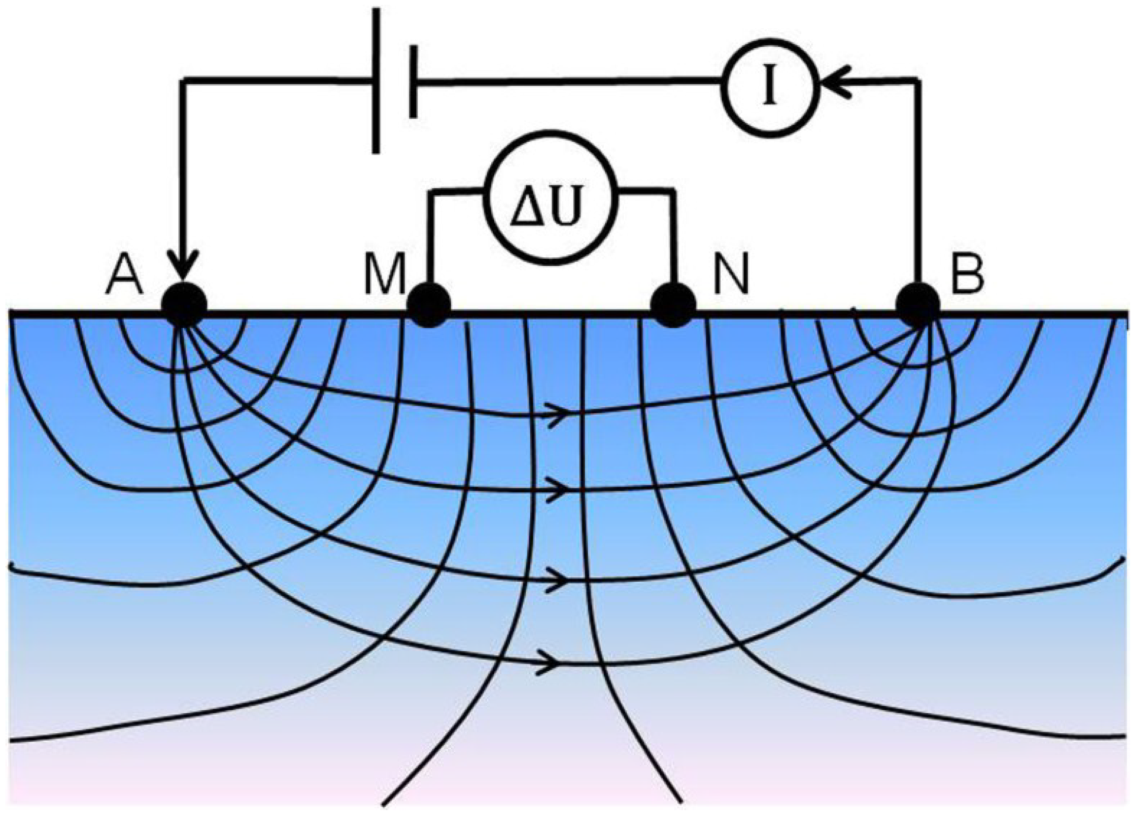
3.1. Principle
The four-point configuration (see
Figure 1) is most commonly used in ERT. As the amplitude modulated periodic current signals are imposed on the exciting electrodes A and B, a stable electric field will be produced. The electric potential difference between measured electrodes M and N can effectively determine the resistivity below the electrodes. In general, the four electrodes have a symmetrical arrangement. As AM = MN = NB =
a, a common Wenner configuration is constructed; while AM = NB =
na and MN =
a, herein
n is the ratio of the distances between the A-M and the M-N electrodes, and it is a standard Schlumberger configuration being sensitive to the survey depth. Considering the small size of Li-ion cells, the survey lines on the cells may not be long enough to place a sufficient number of electrodes, thus the four-point Schlumberger configuration would be suitable to obtain enough survey depth.
Figure 1.
Common four-point surface resistivity measurements.
Figure 1.
Common four-point surface resistivity measurements.
There have been some publications regarding multi-electrode resistivity measurements of structures with ERT [
23,
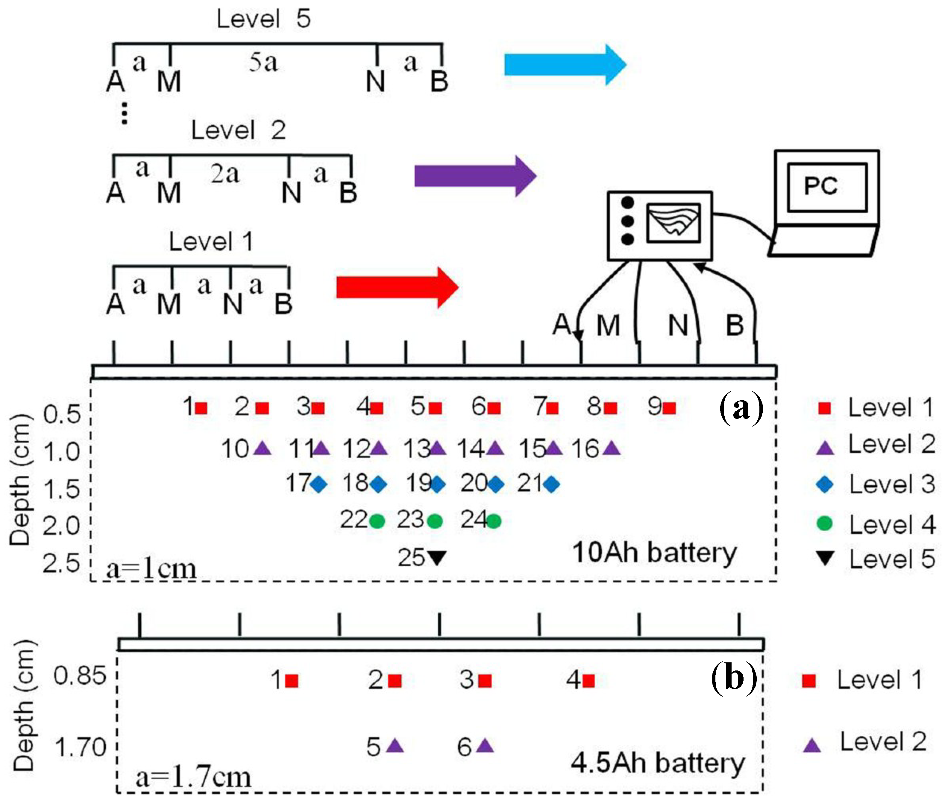
24], but few of them have been written on using this technique for condition assessment of Li-ion cells. However, to map property gradients over depth or perform ERT, multiple measurements using point electrodes at different offsets are necessary. Based on the four-point Schlumberger configuration, the 7-electrode and 12-electrode surface resistivity probes were developed for on-site cell testing application (see
Figure 2). After all voltage measurements are finished, the resistivity value ρ for the Schlumberger configuration is derived by:
where,
I is the exciting current amplitude, and the geometrical factor
G can be defined analytically for the infinite half-space as:
Figure 2.
Distribution of blocks from multi-electrode probe measurements based on Schlumberger configuration. (a) Twenty-five blocks in five levels obtained from 12 electrodes for 10 Ah battery; (b) Six blocks in two levels obtained from seven electrodes for 4.5 Ah battery.
Figure 2.
Distribution of blocks from multi-electrode probe measurements based on Schlumberger configuration. (a) Twenty-five blocks in five levels obtained from 12 electrodes for 10 Ah battery; (b) Six blocks in two levels obtained from seven electrodes for 4.5 Ah battery.
Due to the inhomogeneous nature of a battery cell, the measured resistivity ρ called the apparent resistivity cannot represent the real resistivity ρ
0, which is mainly affected by the current density. Assuming the condition inside the battery is homogeneous, the uniform current density is
j0 while the actual current density in region M-N is
jMN. The apparent resistivity ρ
MN of this region can be expressed as:
As shown in Equation (3), the ρMN is proportionally related to ρ0. Especially when the materials below the region M-N are in a low impedance condition, the current will be drawn to make the surface current density decrease, namely jMN < j0 and ρMN < ρ0; whereas the current will be rejected when the materials remain in a high impedance state, namely jMN > j0 and ρMN > ρ0. Therefore, the changes and distribution of the real resistivity can be determined by the measured apparent resistivity.
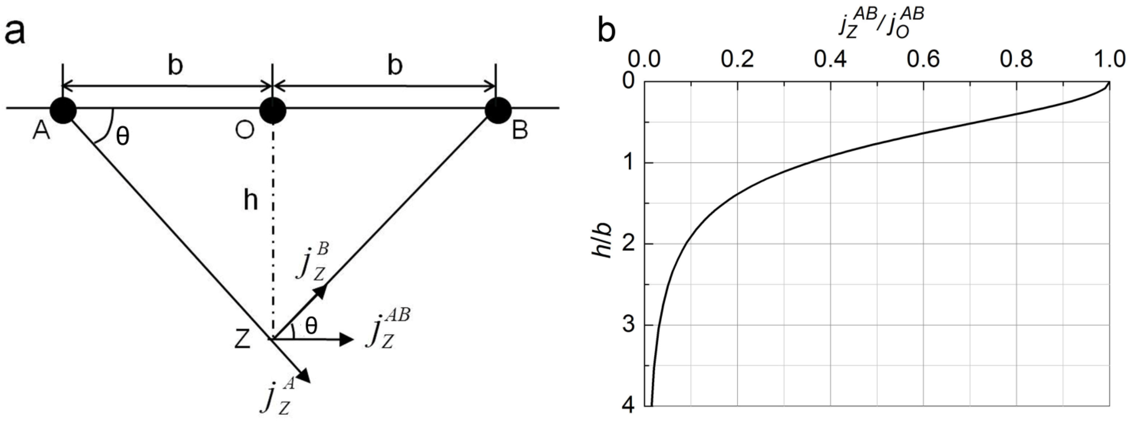
3.2. Survey Depth
In the ERT method described previously, the median depth of investigation can be analytically related to the electrode spacing for the homogeneous infinite half-space [
25]. For inhomogeneous conditions in Li-ion cells, the survey depth theoretically depends on the current density. As effected by the original exciting current density
and
, the current density
in the midpoint O of the AB line in
Figure 3a can be expressed as:
where
is the spacing between the O and A (or B) points. Furthermore, the current density
in the point Z at depth
decomposes into the vectors
and
:
Combining the Equations (4) and (5):
Figure 3b shows a nonlinear relation between
and
. It can be found that the current density is more intensive in the shallow region and decreases sharply with the increase of survey depth. For example, the current density
is only 8.9% of the original when
. In practice, an empirical Equation (7) can be helpful for determining the depth,
:
Herein, is the depth calibration factor. It is suggested that a lesser value of could be suitable for the measurements in shallower regions where the current density is intensive. Correspondingly, as the survey depth increases, a larger value can be a sensible choice.
Figure 3.
(a) Vector decomposition of current density in vertical direction; (b) Variations of current density with depth, as virtually depends on .
Figure 3.
(a) Vector decomposition of current density in vertical direction; (b) Variations of current density with depth, as virtually depends on .
3.3. Impact of Temperature and SOC on Resistivity
The resistivity of any conductor not only depends on its material properties but also on the temperature. In a narrow temperature range, the resistivities of most metal conductors display a linear change [
26]. However, the internal material of a Li-ion cell is not composed of pure metallic elements but rather some complex material units,
i.e., organic electrolyte, electrodes, SEI,
etc. Therefore, the assumption of whether the linear relationship is still suitable for the Li-ion cell still needs to be validated in ERT.
Somehow the various materials and temperatures have a significant dependence on the cell’s SOC [
27], as reported in the literature [
28,
29,
30]. The properties of the anode are affected prominently [
28]; the internal resistance and capacity also display significant changes [
29]. Moreover the electrolyte concentrations would suffer from a strong effect [
30]. Consequently, it is essential to investigate the impact of temperature and SOC on the apparent resistivity simultaneously in experiments. The experimental setup will be described in the next section, followed by a comprehensive discussion of the research results.
4. Experiments
4.1. Materials and Equipment
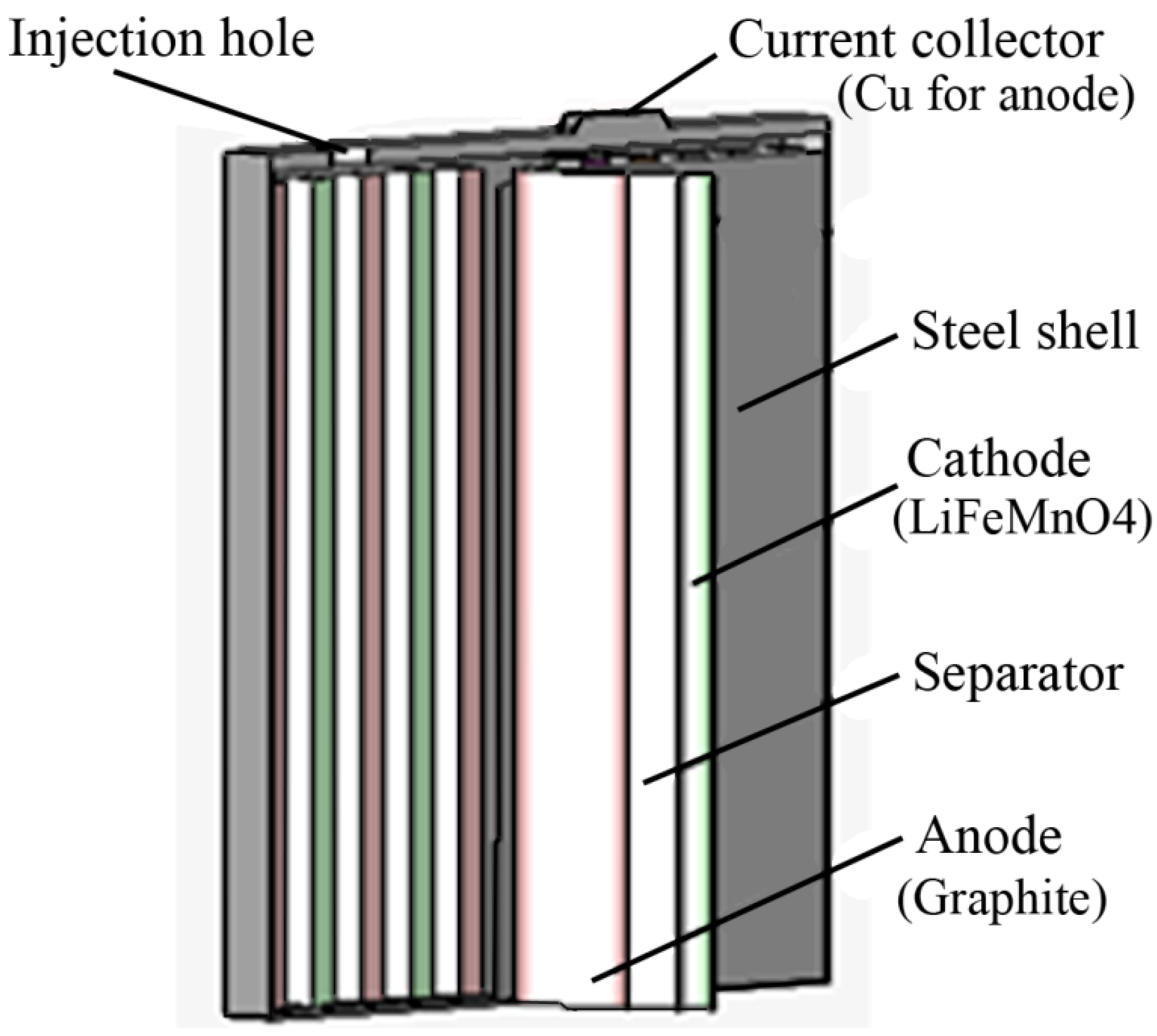
In order to build a stable electric field, two main challenges should be addressed. Firstly the required battery shell in ERT test has to be non-insulated. Thus, two jelly-roll types of commercial steel shell Li-ion cells were tested in this paper, a 10 Ah Phylion IFP16/65/126(10) PAP and a 4.5 Ah Phylion IFP11/65/124(4.5) PAP. Detailed information can be found in
Figure 4 and
Table 1. Secondly, the conductivity of the electrode must be larger than that of the steel shell. Therefore, red copper has been chosen in the experiment for the electrode material, allowing for its economical and practical advantages.
Figure 4.
Schematic diagram of the internal cell structure of the batteries used in the experiments. As the battery is symmetrical, the figure only shows half of the structure. The other half has the same conditions, except the current collector (Al for cathode).
Figure 4.
Schematic diagram of the internal cell structure of the batteries used in the experiments. As the battery is symmetrical, the figure only shows half of the structure. The other half has the same conditions, except the current collector (Al for cathode).
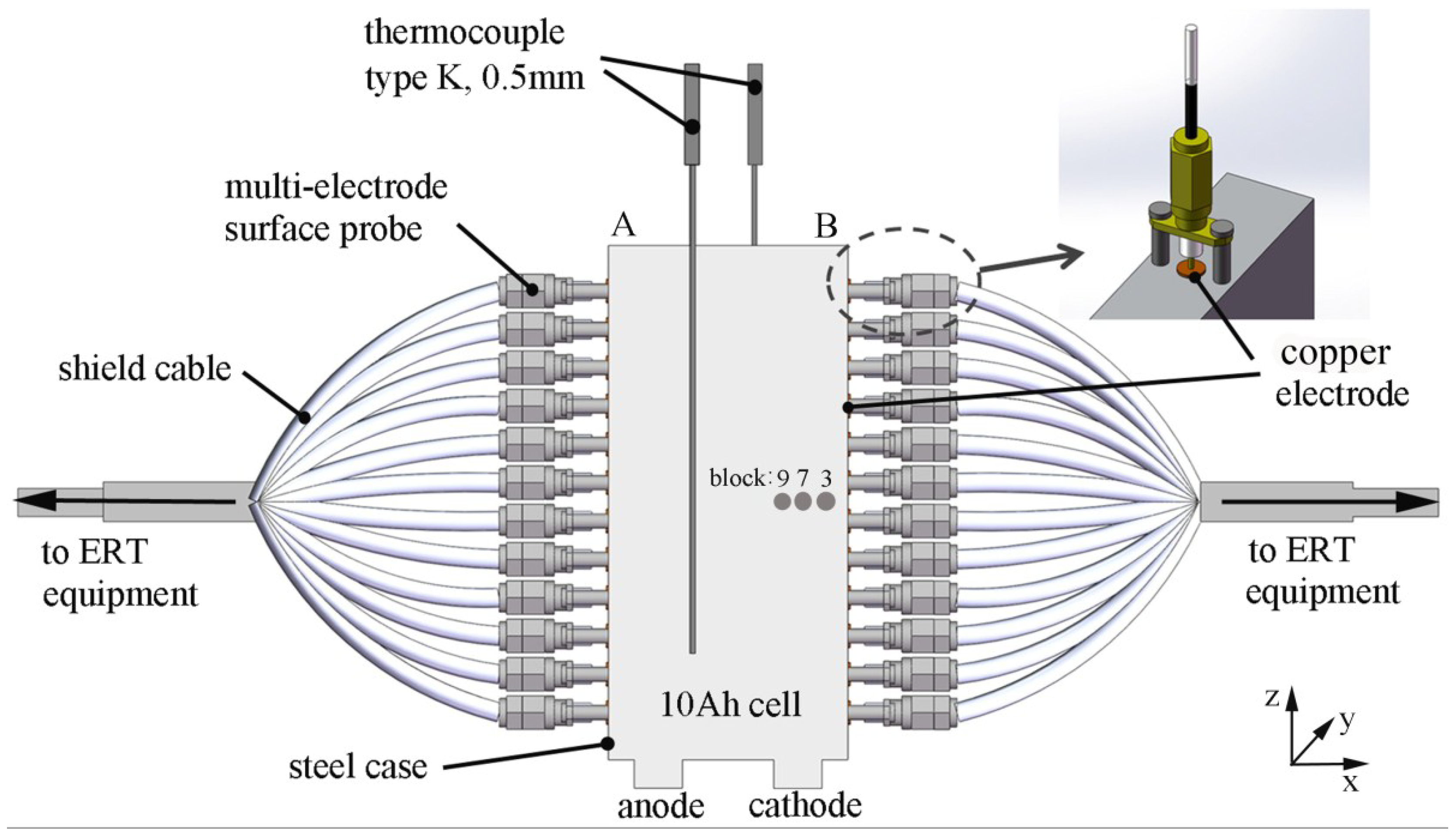
As described in
Section 3.1, the four-point Schlumberger configuration was applied in the experiments described below. Allowing for the cell size, the multi-electrode resistivity array consists of several round red copper electrodes (5 mm diameter by 0.5 mm thickness). For the 10 Ah battery cell in
Figure 5, 12 electrodes were arrayed on the narrow side A of 16 mm width by 126 mm length, and the spacing of two adjacent electrodes remained at 10 mm. According to
Section 3.2, the survey depth can reach 25 mm at most. In order to increase the survey depth and ensure the survey integrity, another 12 electrodes were arrayed on the other narrow side B in the same way. Then as for another 4.5 Ah battery cell, there were only 7 electrodes arrayed on the side A with 17 mm spacing.
Table 1.
Specifications of the investigated Li-ion cells.
Table 1.
Specifications of the investigated Li-ion cells.
| Cell Brand | Phylion | Geometrical Cell Type | Square |
|---|
| Cathode material | LiFeMnO4 | Nominal Capacity (Ah) | 10(4.5) |
| Anode material | Graphite | Length (mm) | 65 |
| Shell material | Steel | Width (mm) | 16(11) |
| Shell resistivity (ohm·m) | 5 × 10⁻⁷ | Height (mm) | 126(124) |
| Separator material | Polypropylene | Nominal voltage (V) | 4.2 |
Figure 5.
Experimental set-up to apply a multi-electrode resistivity probe on the used 10 Ah cell connected by shield cables. Surface temperatures on top and bottom of the cell are measured with thermocouples type K from the temperature-inspecting instrument. The local temperatures for blocks 3, 7 and 9 are determined in
Section 5.4.
The experiment platform mainly consists of four parts: ERT acquisition system, climate chamber, temperature inspecting instrument and upper computer. The independently developed ERT acquisition system connects the copper electrodes via the shield cables to perform the apparent resistivity measurements. To avoid the electrochemical reaction on the copper electrodes, a current excitation signal can effectively eliminate the influence of contact resistance [
31]. A bi-directional pulse current [
32] of 2 mA amplitude with 1 ns polarity switching time was chosen. All experiments were carried out inside an Espec QW1070P6W15 climate chamber with volume at 1 m
3 (Espec Corp., Tokyo, Japan). It provided a defined thermal environment for the cell itself as described in
Table 2 and
Table 3. To estimate the hold time at certain temperature in the chamber, a Yokogawa MV2000 temperature-inspecting instrument (Yokogawa Electric Corp., Tokyo, Japan) was applied to measure the cell surface temperature via two thermocouples (type K). After the measured surface temperature reached the setting temperature, a period of 0.5 h would be allowed for temperature equilibration inside the Li-ion cell. Finally, subsequent data processing and image reconstruction can be achieved further by the upper computer, where 2D and 3D geo-electrical imaging software Res2dinv distributed by Geotomo Software (Penang, Malaysia) can accomplish the function of image reconstruction.
4.2. Feasibility Analysis
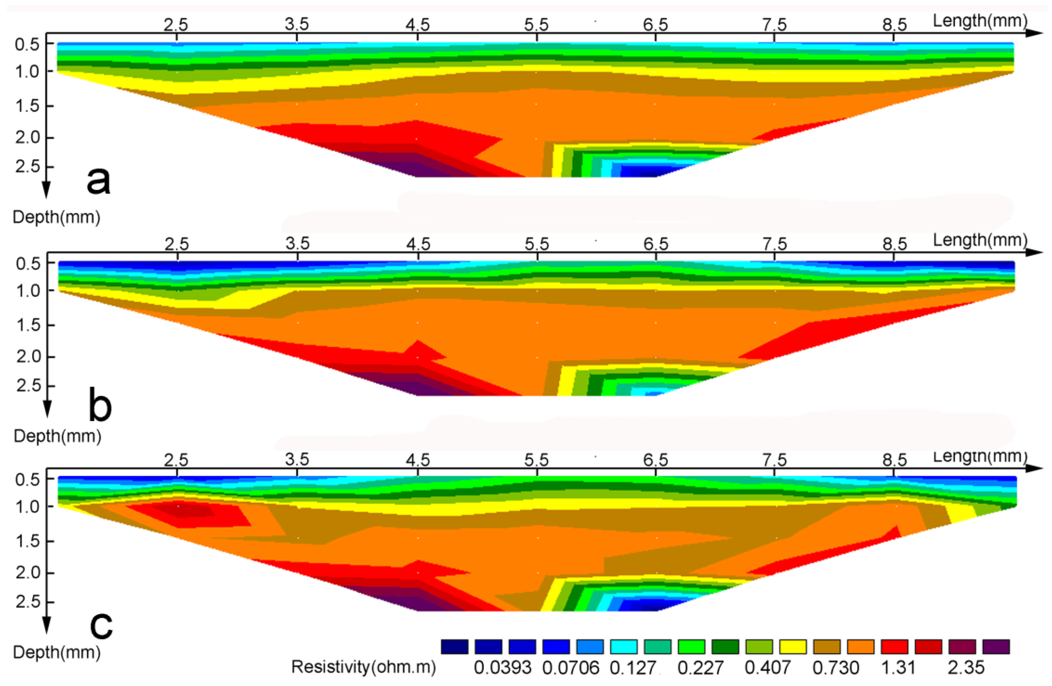
In order to validate the feasibility of ERT method, preparatory work was carried out on side A of a 10 Ah battery. Repetitive measurements were performed at three different temperatures, namely 0, 25 and 50 °C. Since not all the resistivity values were reproduced here, one representative set of data was chosen for analysis, and three inversion images of resistivity distribution were reconstructed by the upper computer. As shown in
Figure 6, a significant discrepancy of color ribbons can be found in the same region of the three images. This indicates that the temperature has a great influence on internal cell resistivity and local temperature can be further determined by resistivity. Therefore, the dependence of the resistivity on temperature needs to be investigated by future experiments.
Figure 6.
Inversion images of the observed apparent resistivity for side A on 10 Ah battery under three different temperatures (a) 0 °C; (b) 25 °C; and (c) 50 °C. The images reflect the changes of resistivity pseudosection with temperatures.
Figure 6.
Inversion images of the observed apparent resistivity for side A on 10 Ah battery under three different temperatures (a) 0 °C; (b) 25 °C; and (c) 50 °C. The images reflect the changes of resistivity pseudosection with temperatures.
4.3. Experimental Method
To investigate the relationship among the resistivity, the local cell temperature, and the SOC, the entire process was divided into three independent experiments. In addition, repetitive measurements were carried out in each experiment.
4.3.1. Effect of Homogeneous Temperature on Resistivity
At first, the resistivity was measured with a homogeneous temperature distribution. In order to check the reproducibility, the entire procedure was independently carried out on two cells with different capacity, a 10 Ah cell at SOC of 5% and a 4.5 Ah cell at SOC of 100%. The climate chamber adjusted the temperature stepwise from −20 to 80 °C according to
Table 2.
∆T is the difference of two adjacent temperature adjusted by the climate chamber. Resistivity measurements were performed at each temperature after equilibrium time. When the surface temperature reached a setting value monitored with calibrated thermocouples (K type) from the temperature inspection instrument, the cell stepped into the temperature equilibration period. After this period of time, resistivity measurements were performed on sides A and B independently (only side A for the 4.5 Ah cell).
Table 2.
Inhomogeneous temperature distribution.
Table 2.
Inhomogeneous temperature distribution.
| ∆T (K) | - | 10 | 10 | 10 | 5 | 5 | 5 | 5 | 5 | 5 | 5 | 5 | 10 | 10 | 10 |
| T (°C) | −20 | −10 | 0 | 10 | 15 | 20 | 25 | 30 | 35 | 40 | 45 | 50 | 60 | 70 | 80 |
4.3.2. Effect of SOC on Resistivity
In this experiment, the effect of SOC on resistivity was investigated on 4.5 Ah battery cell. All resistivity measurements were implemented on the same battery cell to eliminate interference resulted from individual difference. The state of SOC was set from 90% to 10% with a decrement of 20% by DC discharge, and at each SOC the climate chamber adjusted the temperature, respectively, to three temperatures 0, 25 and 50 °C. After the temperature equilibration period, the resistivity was measured. This work facilitates the evaluation of the dependence of the resistivity on SOC.
4.3.3. Effect of Transient Temperature on Resistivity
Finally, the development of the internal temperature during a cool down process was investigated on the 10 Ah cell at a 100% charge. The number of electrodes decreased to eight to ensure the stability of resistivity, according to
Section 5.1. During this experiment the surface temperatures were determined with type K thermocouples at three different positions (see
Figure 5), corresponding to blocks 3, 7 and 9 at different levels. The chamber temperature
was set to 0 °C and a constant electronic load was imposed on the 10 Ah cell with a larger discharge current at an amplitude of 20 A. After half an hour, the cell surface temperature reached the thermal steady state with a temperature of approximately 42 °C and the SOC of the cell reduced to nearly 10% of full charge. To simulate the real cool process, the climate chamber was switched off after discharge, and the resistivity measurements were promptly performed at periodic intervals. The surface temperature
Tsurf was recorded by thermocouple.
5. Results and Discussion
The conducted experiments focus on the correlation among the local temperature T, SOC and the apparent resistivity ρ for the steel shell Li-ion cells. In addition, the analyses of the two different cells helps to validate the relation as proposed below, and further reinforce the link between ρ and .
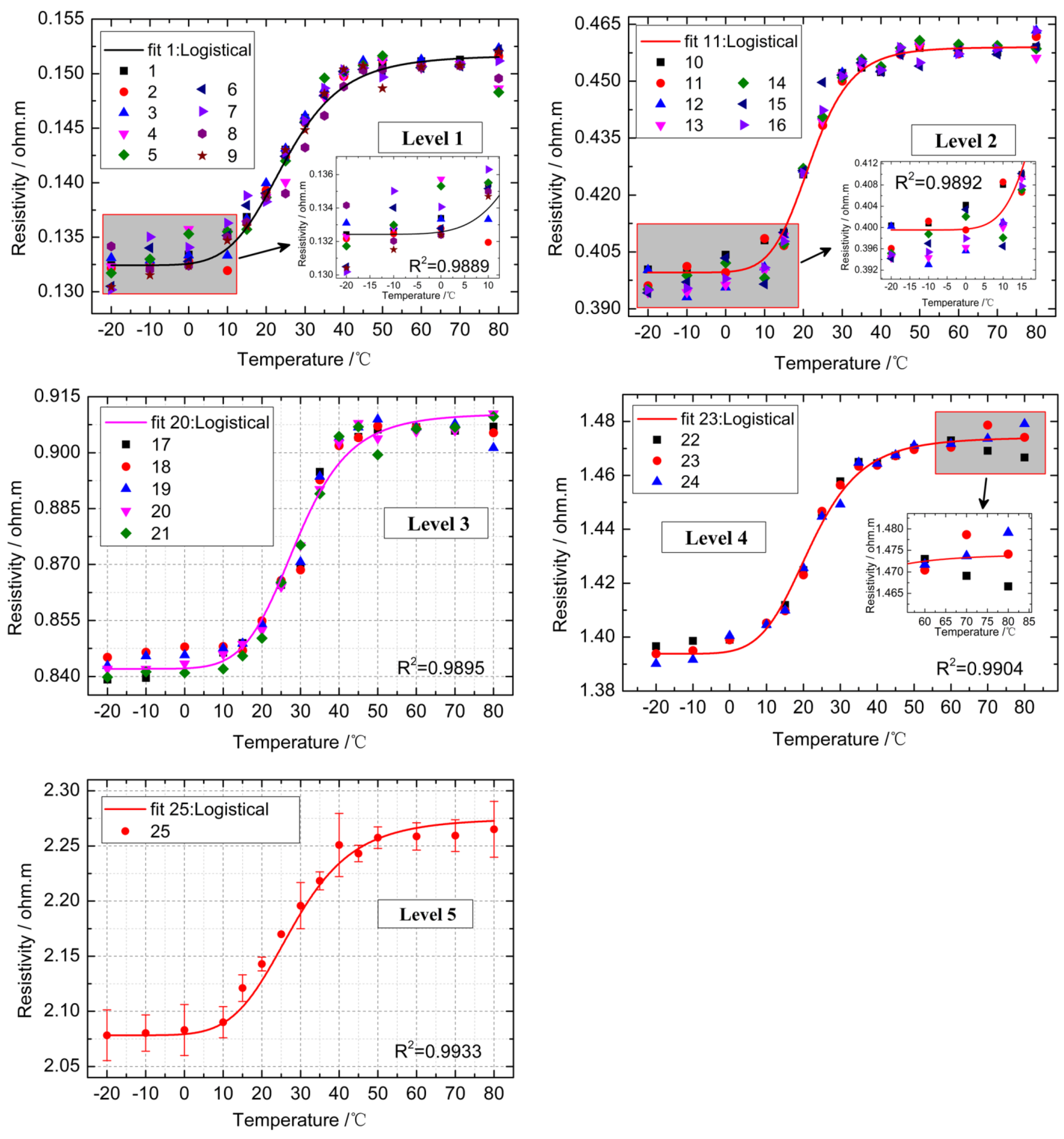
5.1. Effect of Constant Temperature on Resistivity
Just as shown in
Figure 2, the resistivity values of 25 blocks in five levels were measured for the 10 Ah cell. Not all the resistivity values are reproduced here. One representative set of data for each level in sides A and B is shown in
Figure 7 and
Figure 8. It is evident from the data of side A in
Figure 7 that the temperature (
x-axis) greatly impacted the resistivity (
y-axis). In addition, the variations of resistivity value with temperature were similar for all 25 blocks. As to the side B in
Figure 8, it is seen that the dependence of the resistivity on temperature is also similar to the side A. Except for levels 4 and 5, the values of the resistivity in side B are slightly smaller. One possible reason is the concentration difference of the internal ionic conducting liquid. However, this doesn’t affect the main trend. Thus, the linear relation assumed in
Section 3.3 is adequately refuted by the nonlinear growth relationship between the resistivity and temperature seen in
Figure 7 and
Figure 8.
Figure 7.
Variations of block resistivity ρ with temperature
in side A for 10 Ah cell with SOC of 5%. All data in the graphs are the average of ten independent measurements. The dotted lines are the logistical fit to the representative blocks discussed in
Section 5.2.
Figure 7.
Variations of block resistivity ρ with temperature
in side A for 10 Ah cell with SOC of 5%. All data in the graphs are the average of ten independent measurements. The dotted lines are the logistical fit to the representative blocks discussed in
Section 5.2.
Figure 8.
Variations of block resistivity ρ with temperature
on side B of 10 Ah cell with SOC of 5%. All data in the graphs are the average of ten independent measurements. Some unstable data regions are magnified for discussion in the graphs. The dotted lines are the logistical fit of all the representative blocks discussed in
Section 5.2.
To better analyze the experiment’s results, the entire temperature range is divided into three sections: dormant region (−20–0 °C), exponential region (0–50 °C) and exhausted region (50–80 °C). In the first dormant region, the resistivity value seems to have a weak correlation with temperature. The same results have been achieved in repeated measurements. This indicates that low temperature environments reduce the performance of the materials inside a cell [
33], which produces an inconspicuous variation in resistivity. Then, in the exponential region (0–50 °C), the material activity is revived as the temperature gradually rises. Here, we believe that the required performance of most Li-ion cells can be achieved, and a suitable temperature environment will benefit the health of a battery cell. Finally, in the exhausted region (50–80 °C), higher temperatures abruptly hinder the rise of the resistivity. In this serious situation, it seems easy to cause the breakdown of a battery cell: changes in the properties of the anode occur at temperatures well below 55 °C [
34] and the surface film on the graphite in contact with electrolyte indicates that reactions occur at temperature as low as 60 °C [
35]. However, due to the proprietary aspects of these two commercial products, this information was not available for our experiments.
Note that both in the dormant region (−20–0 °C) and the exhausted region (50–80 °C), the resistivity value changes slightly but unsteadily. Especially for the side B in
Figure 8, some amplified details of the data distributions in these two regions have described the unstable circumstance. At this point, it is generally hard to distinguish the local temperature via the block resistivity. The main cause lies in the extreme temperature environment, which has a great influence on the material properties [
33]. Additionally, by comparing other blocks in
Figure 8, the resistivity values of block 9 drift greatly at low temperatures. While the baseline of the curve shifts, there isn’t a corresponding shift in the high temperature behavior, lining up with the other data. As block 9 is too close to the edge and corner of the cell, we preliminarily consider this result may be attributed to material conditions to a large degree, such as lower electrolyte concentrations, which show a poor low temperature characteristic.
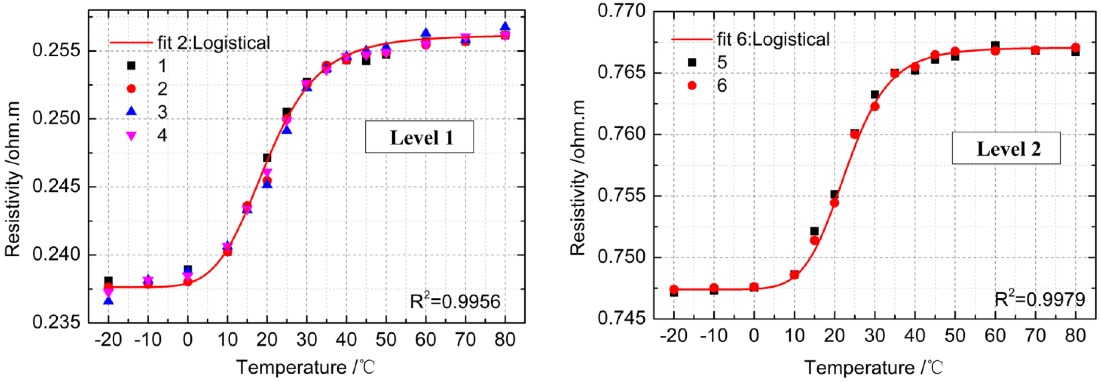
The instabilities and variances discussed above are indicators for the good reproducibility of the ERT method according to the influence of measurement errors and environment system errors. However, two main questions need to be resolved in this experiment. One is whether the relationship between the block resistivity and the temperature is consistent in other cells with different capacity. Another is how to improve the stability of resistivity data. Thus, another 4.5 Ah battery cell was examined only on side A, and we tentatively decreased the number of electrodes to seven.
Figure 9 shows the scatter plot of the resistivity
versus the temperature and provides key clues to answer these questions.
Figure 9.
Variations of block resistivity ρ with temperature
on side A of 4.5 Ah cell with nearly SOC of 100%. All data in the graphs are the average of ten independent measurements. The dotted lines are the logistical fit to the representative blocks discussed in
Section 5.2.
Figure 9.
Variations of block resistivity ρ with temperature
on side A of 4.5 Ah cell with nearly SOC of 100%. All data in the graphs are the average of ten independent measurements. The dotted lines are the logistical fit to the representative blocks discussed in
Section 5.2.
Firstly it is obvious that similar correlations do exist in the 4.5 Ah cell at the same temperatures (−20–80 °C), so it can be concluded that a unique correlation between the temperature and the resistivity exists at least in all cells of the same type. Secondly, it has also been found that the apparent resistivity data becomes more stable as the number of electrodes decreases to seven, especially in the dormant region (−20–0 °C) and the exhausted region (50–80 °C). According to Equation (7), the survey depth reaches 17 mm with only six blocks in two levels, 41.2% deeper than that in the first two levels in a 10 Ah cell, which means the block size is amplified. In other words, it is implied that the data sensitivity can be improved at the cost of decreasing the local temperature resolution.
So far, the correlation between the temperature and the resistivity has been confirmed by the two experiments. Then the next task is to evaluate this relationship using a suitable fitting equation, as will be demonstrated in the next section.
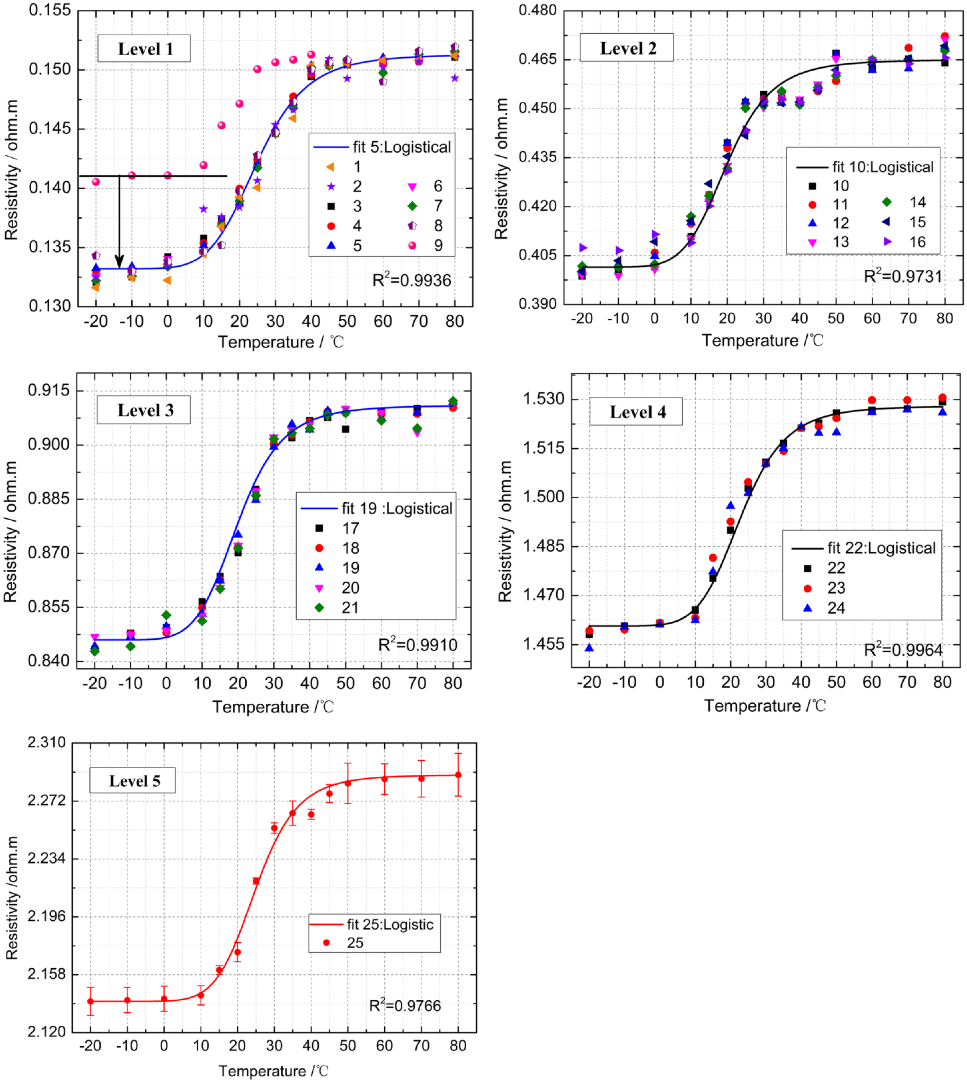
5.2. Determination of Local Cell Temperature
In
Section 3.3, it has been shown that the apparent resistivity ρ not only depends on the material properties but also temperature. In a small temperature range, the resistivity of most metal conductors can be deduced by a linear equation (Equation (8)):
where
is the current temperature, and
presents the resistivity value at 0 °C, and
denotes the temperature coefficient of resistivity. Although Equation (8) is unsuitable to derive the temperature with the resistivity value in
Figure 7,
Figure 8 and
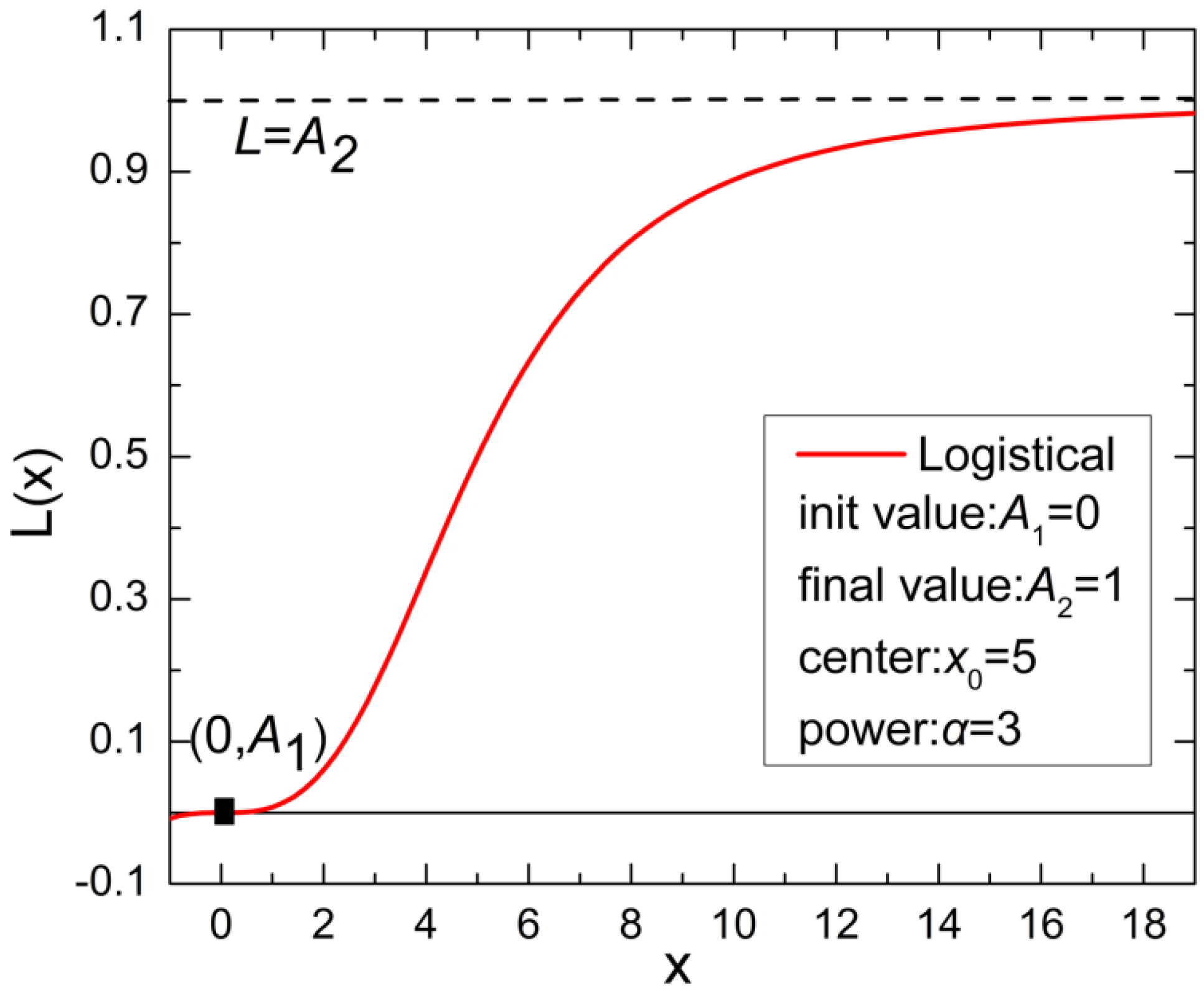
Figure 9, it is found that the dependence of the resistivity on temperature is approximated with a conventional logistical behavior of (see
Figure 10):
with
,
,
and
being constant coefficients.
Figure 10.
The simplified curve of the logistical fit function . The parameters have been defined as constant values in the graph.
Figure 10.
The simplified curve of the logistical fit function . The parameters have been defined as constant values in the graph.
Considering the correlations between the resistivity and the temperature in the two battery cells have a high resemblance, several representative blocks from each level (see
Figure 7,
Figure 8 and
Figure 9) are chosen to fit in the light of
Table 3 and
Table 4. Furthermore, the modified Equation (10) is used for fitting the block resistivity, where
is plotted
versus the temperature
T (−20–80 °C):
where
and
are the maximum and minimum values of the measured resistivities, and
and
are the fitted parameters.
Table 3 and
Table 4 show the values of these parameters. By comparing the fitting results of each block, a good relevancy can be seen with the fitting correlation coefficient
above 0.97.
Table 3.
Fitted parameters of representative blocks of sides A and B on 10 Ah cell.
Table 3.
Fitted parameters of representative blocks of sides A and B on 10 Ah cell.
| Cell Type | 10 Ah |
|---|
| Side | A | B |
|---|
| Block | 5 | 10 | 19 | 22 | 25 | 1 | 11 | 20 | 23 | 25 |
|---|
| ρmax | 0.1513 | 0.4650 | 0.9110 | 1.5280 | 2.2893 | 0.1517 | 0.459 | 0.9105 | 1.4741 | 2.2751 |
| ρmin | 0.1332 | 0.4015 | 0.8460 | 1.4607 | 2.1404 | 0.1324 | 0.3996 | 0.8420 | 1.3938 | 2.0783 |
| T0 | 45 | 40 | 40 | 43 | 45 | 40 | 42 | 49 | 42 | 48 |
| α | 6.5 | 6.4 | 6.5 | 6.8 | 8.0 | 6.0 | 8.0 | 7.0 | 6.0 | 6.0 |
Table 4.
Fitted parameters of representative blocks of side A on 4.5 Ah cell.
Table 4.
Fitted parameters of representative blocks of side A on 4.5 Ah cell.
| Cell Type | 4.5 Ah |
|---|
| Side | A |
|---|
| Block | 2 | 6 |
|---|
| ρmax | 0.2562 | 0.7630 |
| ρmin | 0.2376 | 0.7150 |
| T0 | 40 | 44 |
| α | 6.5 | 9.0 |
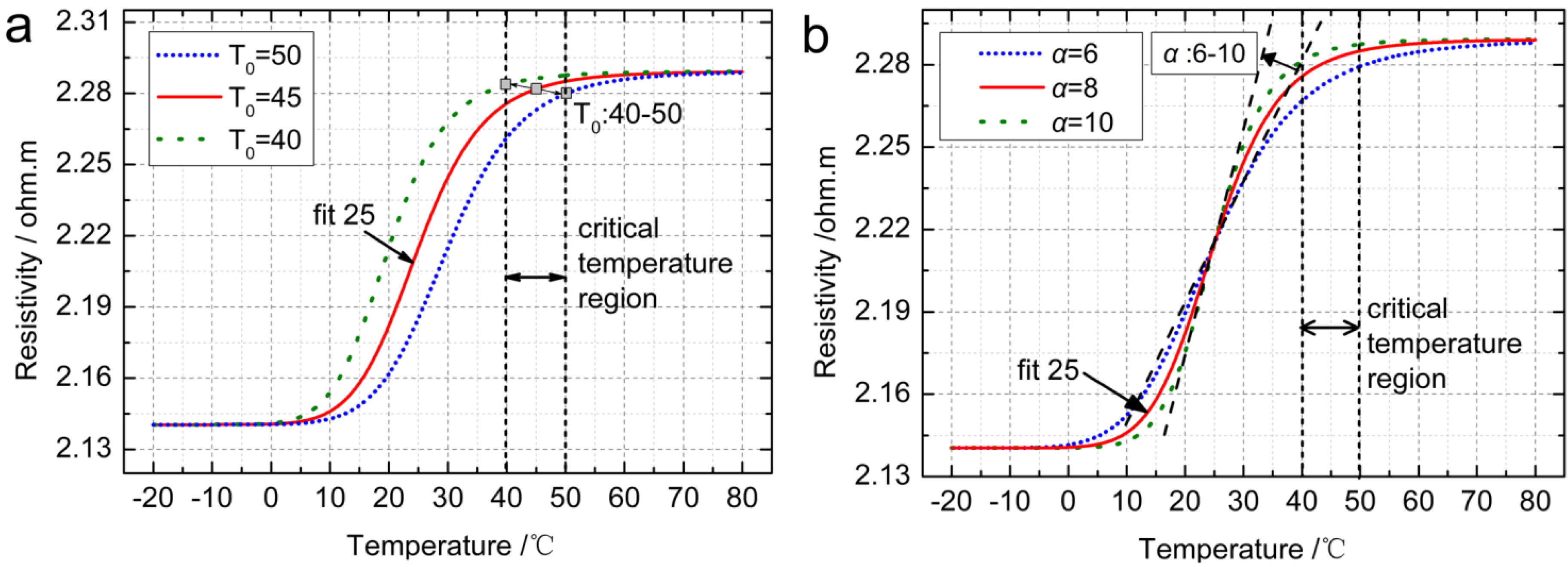
In general, a unified equation can be established based on the discussion on the physical definition of the four fitted parameters
. A2 and
A1 in
Figure 10 indicate that the parameters
and
can be, respectively, defined as the resistivity value at the highest and lowest temperatures, which represent the extensibility of the cell material resistivity. Considering that the coefficient
T0 is defined as a saturation value in species and shows a range from 40 to 50 in
Table 3 and
Table 4, the range can be further defined as a critical temperature region with the growth rate of the resistivity slowing down rapidly at the temperatures between 40 and 50 °C (see
Figure 7,
Figure 8 and
Figure 9). Therefore,
T0 is regarded as the specific critical temperature varying in different cells. Moreover,
Figure 11a implies that the saturation characteristic of material resistivity
versus temperature can be determined by the critical temperature
T0. Thus, it is concluded that the higher
T0 value the battery has, the better performance it will have. The final parameter α also plays a critical role in Equation (10). Just as described in
Figure 11b, the steeper trend of the resistivity can be determined by the larger α value in the exponential region, approaching a vertical line when α = 10 or more. Consequently, the α can be defined as the growth factor of resistivity, determining the variation width of resistivity in
x-axis direction.
As discussed above, the larger span between
and
, the greater
and the smaller α indicate an optimum condition of the resistivity
versus temperature characteristic for Li-ion cells and a low damage probability resulting from thermal shock. This is a great, meaningful finding for ensuring security and prolonging the service life for Li-ion cells. Furthermore, by comparing the resistivity values of all blocks in the same levels (all in
Figure 7,
Figure 8 and
Figure 9), no significant discrepancy can be seen. For all data,
and
can be simplified as:
where
and
represent the resistivity value of block
in level
at 0 and 50 °C, respectively. Using the algebraic mean value of the block resistivities in the same level can be a valid substitute for these two parameters. However, a remarkable discrepancy of the resistivity values among different levels is observed. Nevertheless, according to the definition of the geometrical factor
in Equation (1), an implicit similar relation exists in Equation (12):
Figure 11.
(
a) Comparative analysis of
T0 at different values; (
b) Comparative analysis of α at different values. The values are selected from
Table 3 and
Table 4. The logistical fit line of the block 25 in
Figure 7 is chosen as the reference line.
Figure 11.
(
a) Comparative analysis of
T0 at different values; (
b) Comparative analysis of α at different values. The values are selected from
Table 3 and
Table 4. The logistical fit line of the block 25 in
Figure 7 is chosen as the reference line.
Therefore,
and
in different levels can be determined uniformly by Equations (11) and (12). Considering the complex structure inside Li-ion cells, currently there is no valid evaluation for
and
, but a measured range has been achieved, namely
,
. Additionally within the temperature range from 0 to 50 °C, the local temperature could be more recognizable. So the dependence of the resistivity on the temperature (0–50 °C) will be utilized in the presented method to determine the local cell temperature using the inverse function (13) in ERT:
Note that Equation (13) is developed for the first time through a careful and painstaking analysis. The parameters are interpreted physically and the improved logistical approach already describes the measurement results accurately in temperature range from 0 to 50 °C. As HEV/EV cell packs usually operate at a higher temperature than 50 °C, the challenging improvements on accuracy of this method in extreme temperature will have to be the subject of future work, and further applications in onboard equipment will be a key trend.
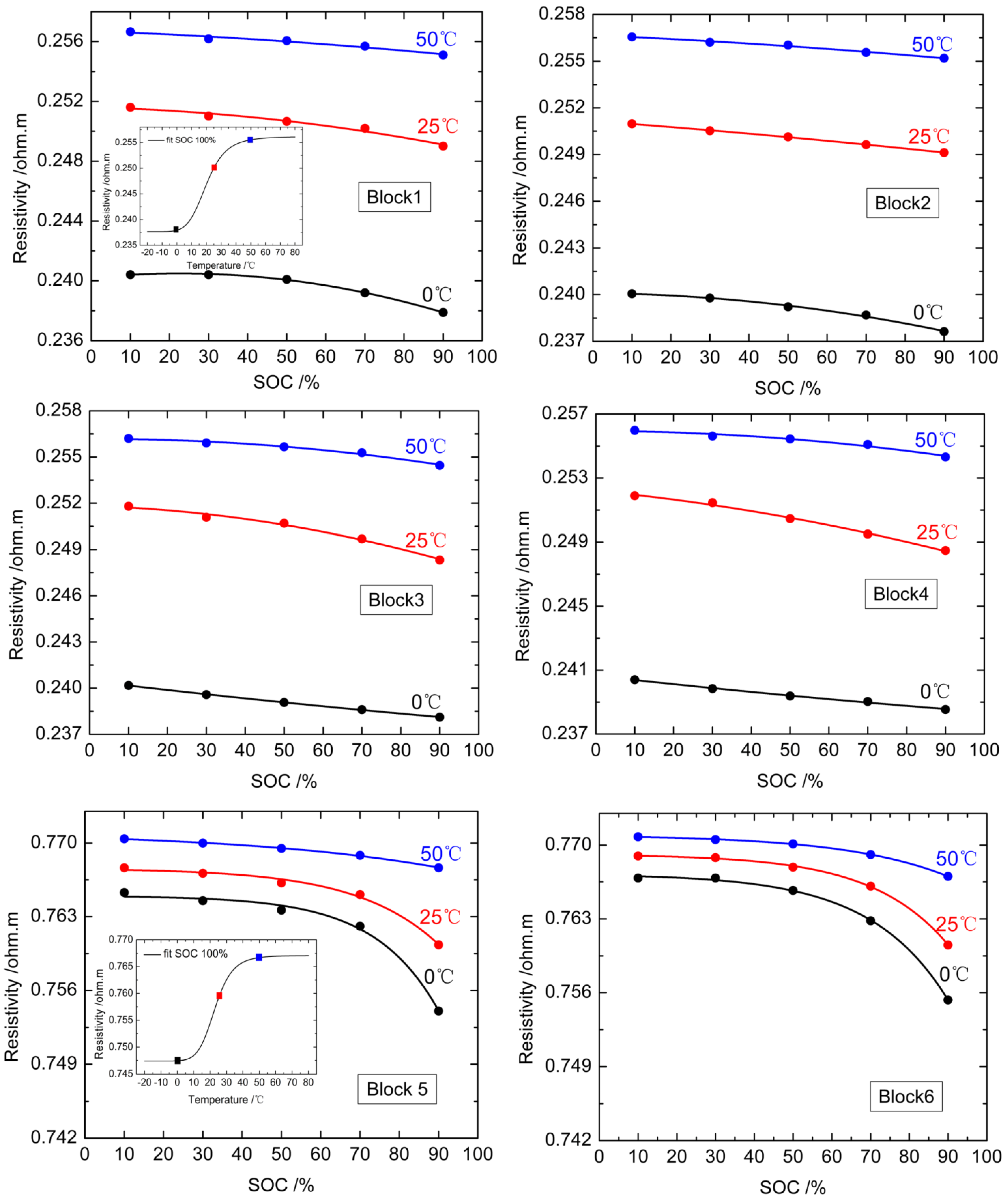
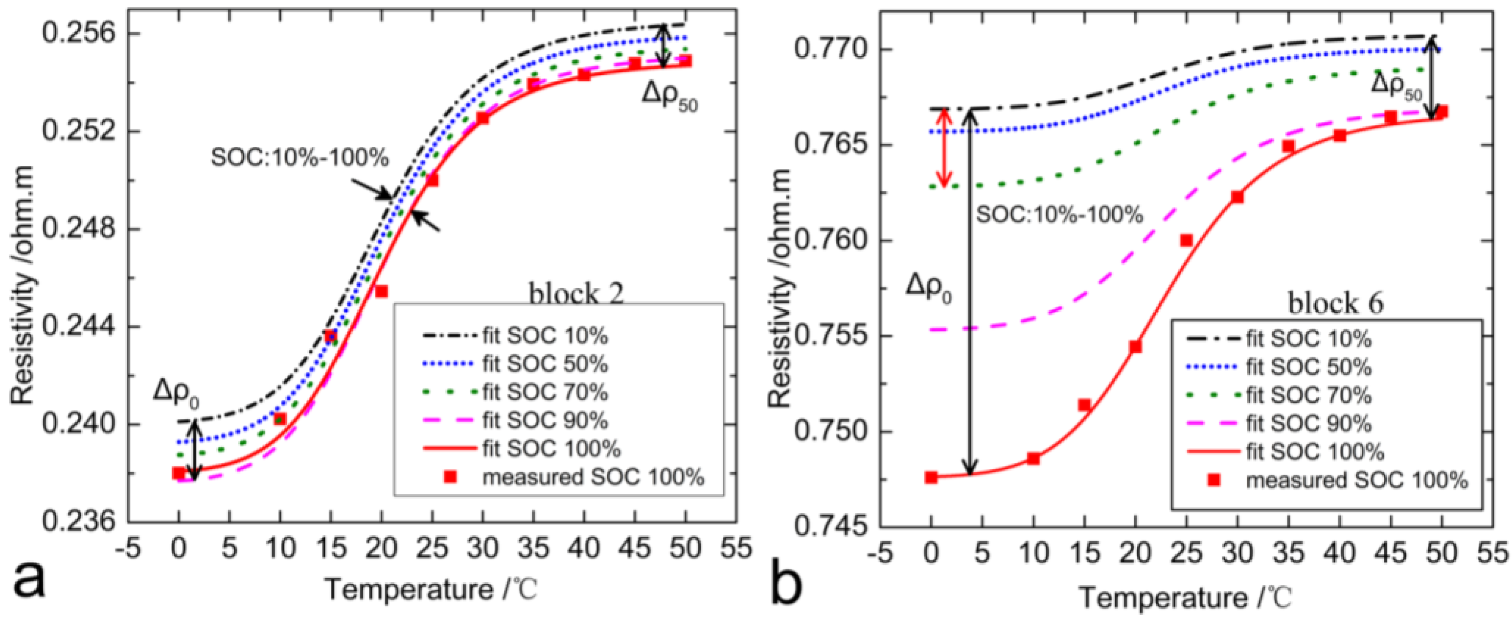
5.3. Effect of SOC on Resistivity
At different SOCs, the concentrations of Li
+ and electrolyte vary significantly. This is quantified by the resistivities using the 4.5 Ah cell as an example in
Figure 12, where the ρ is plotted
versus the SOC for varying temperatures. The colored lines are fitted by the attenuation index function (14):
where
is the measured resistivity value when SOC
= 0,
and
are the fitted coefficients.
Figure 12 illustrates the correlation between the SOC and the resistivity at 0, 25 and 50 °C. Without exceptions at a certain constant temperature, the resistivity decreases with the increase of SOC. Meanwhile, affected by three different temperatures, the spans of the characteristic SOC-
curves are obvious. As the temperature rises up, the SOC-
curve is more like a straight line, which means a weak correlation exists between SOC and
at higher temperatures.
More specifically, by comparing the downward trend of all SOC- curves at the first level, no significant discrepancy can be seen except the effect of temperatures. Similarly, the resistivity at level 2 also has a slow and linear downtrend in the SOC ranging from 0% to 70%. However, in contrast, when the SOC is higher than 70%, the resistivities reduce substantially, especially at 50 °C or higher. We believe that two main factors determine this difference, namely the investigated depth and the material characteristic in corresponding level. In the superficial layer, the concentrations of Li+ and electrolyte are relatively low and the influence of SOC and temperature on resistivity will be not notable. As the depth increases, the distribution of electrolyte is homogeneous, but the state of Li+ will change due to the cell charge and discharge process. Therefore, at a constant temperature, the effect of SOC on resistivity will be enhanced prominently in deeper or central regions of the cell body.
Here, block 2 and block 6 in different depths of the 4.5 Ah cell have been chosen to further analyze the effects of SOC in
Figure 13. The lines depict the logistic fit according to Equation (10). Here the
and
values remain at SOC of 100% fitted in
Table 3 and
Table 4, the
and
are the resistivity values at 0 and 50 °C, respectively, varying with the different SOCs.
Throughout there is no obvious intersection among those five characteristic
-SOC curves, which means that the SOC generates a vertical drift effect on the
-
curves in
Figure 7,
Figure 8 and
Figure 9. As shown in
Figure 13a, the ρ-SOC curves for the block 2 at different SOCs drift slightly and evenly, and the maximum offset is only 0.00246 ohm·m at a temperature of 0 °C. In contrast, a drastic drift exists in the curves of block 6 (see
Figure 13b), where the maximum span reaches 0.01927 ohm·m at 0 °C while 0.00402 ohm·m at 50 °C. Furthermore, the drift increases when the temperature decreases in accordance with Equation (14).
Furthermore,
Figure 13b also illustrates that the effects of the SOC on resistivity at lower temperatures will be stronger than that at higher temperatures. In addition, those prominent effects only exist in the SOC ranging from 70% to 100%. In general, at least at 80% operating range is typically used for Li-ion batteries and high-energy applications push that even higher. Therefore, the SOC factor should be considered necessarily if the cell local temperature distribution is obtained from the method as described. Here, two levels of the cell have been studied in this experiment. If the method is to be applied in practice, it is necessary to perform complete experiments in follow-up works, e.g., three-dimensional resistivity measurements on broad side of the cell to learn more about the effects in deeper regions. Even so, the local temperatures for the investigated regions in experiments can still be determined according to the Equations (13) and (14).
Figure 12.
Variations of apparent resistivity with SOC in side A of 4.5 Ah battery. Each block in graph is the average of ten independent measurements made at 0, 25 and 50 °C. The dotted lines are the exponential decay fit to all the blocks.
Figure 12.
Variations of apparent resistivity with SOC in side A of 4.5 Ah battery. Each block in graph is the average of ten independent measurements made at 0, 25 and 50 °C. The dotted lines are the exponential decay fit to all the blocks.
Figure 13.
Modified logistical plot of apparent resistivity for a 4.5 Ah battery considering the effect of different SOCs. (
a) The logistical curves of the block 2; (
b) the logistical curves of the block 6. The two blocks are chosen in
Figure 9 as the reference lines, the other four logistical curves for the two blocks are deduced with different
and
at 10%, 50%, 70%, and 90% SOCs.
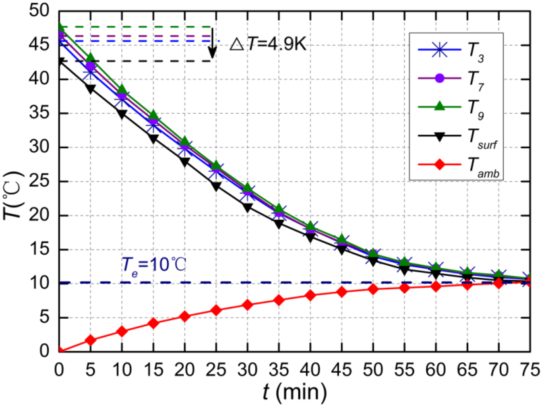
5.4. Effect of Transient Temperature on Resistivity
Resistivity measurements performed in electrochemical equilibrium are commonly suggested, which is similar to the impedance measurement described in Ref. [
15]. Meanwhile, resistivity measurements under an active load are also allowed in operation. However, a built-in electric field will emerge inside the cell during charge and discharge. This will cripple the imposed electric field intensity produced by the bi-directional pulse current signal, and the measurement quality of the resistivity will decrease. Hence, we first concentrate on the influence of the temperature transient on ρ as proof of principle: local temperature, determined as introduced above, is compared with external measurements during a cool down of a previously heated cell.
As described in
Section 5.1, decreasing the number of electrodes does improve the stability of the resistivity data, and only eight electrodes are left on the 10 Ah cell in
Figure 5. Based on the results, a total of three levels and nine blocks can be obtained according to
Section 3.1. The cell operates with a 20 A discharge current, and finally the SOC only remains at 10% of full charge. After switching off the electronic load and climate chamber, the resistivity is directly and repeatedly measured for five minutes during the thermal relaxation phase. From these measured resistivity data, the local temperatures inside the cell are determined under the effect of SOC as demonstrated. Here, the local temperatures of three blocks in different levels (see
Figure 5) are chosen to compare with the measured surface temperature
from the temperature sensors
versus time in
Figure 14.
As shown in
Figure 14, the measured values
drop down normally but do not coincide with the calculated values in the beginning. Meanwhile, three local temperature values determined by resistivity are also not equal to each other. For the block 9 in the third level, the temperature reaches 47.6 °C, at its highest. The next lower temperature represents the block 7 at 46.5 °C. The block 3 in superficial layer is another 0.9 K below this temperature. It is clear that three levels only occupy, at most, 30% of the cell regions according to
Section 3.2. However, the temperature difference reaches to 2 K in this regions and it may be greater in deeper regions. In addition, the measured surface temperature of the cell is 42.7 °C at the lowest. The difference between the surface temperature and local cell temperature is 4.9 K or more in deeper regions. To some degree, this is approximate to the results from a similar experiment conducted by Schmidt [
15]. However, the local temperature measurements instead of the whole mean internal cell temperature measurements will be more meaningful in the future, as already described in the Introduction.
Figure 14.
Measured temperatures after switching off the electronic load for thermal relaxation of the cell in an initial ambient temperature of 0 °C, for three measurement positions of the different local temperatures referred to in
Figure 5.
Figure 14.
Measured temperatures after switching off the electronic load for thermal relaxation of the cell in an initial ambient temperature of 0 °C, for three measurement positions of the different local temperatures referred to in
Figure 5.
On the other hand, the ambient temperature
rises up gradually under a continuous thermal shock in
Figure 14. After some time, the whole space and the battery cell reach a thermal equilibrium state at nearly 10 °C. In other words, a large amount of heat, emanating from the 10 Ah cell at almost 48 °C, spontaneously heats an enclosed space from 0 to 10 °C. This effect will be strengthened for Hybrid Energy Vehicle (HEV/EV) battery packs, which are usually assembled in a narrow space and operate at a high temperature. In reality, however, it is difficult to reach a heat balance between the packs and the environment under charge and discharge. As a result, the cell internal temperature distribution will become more complex inside the packs, which may cause a series of thermal safety problems. This further underlines the importance of local temperature measurements.
In summary, the preliminary evaluation of the resistivity measurements in ERT based on local cell temperature distribution has been demonstrated above. However, applications of this method under an active load in thermal environment need to be addressed in follow-up study.
6. Conclusions and Future Work
This article aims to measure the local temperature inside battery cells by investigating the dependence of resistivity on temperature and SOC. A non-destructive evaluation method using Electrical Resistance Tomography technology was proposed in the battery field. The method was experimentally demonstrated on two steel shell Li-ion battery cells with different capacities (10 and 4.5 Ah), and the four-point Schlumberger configuration was applied in three experiments.
This work demonstrates that the measured resistivities for different blocks in all levels of the two cells correlate well with the local cell temperature. A lesser number of electrodes can enhance the stability of resistivity data but decrease the sensitivity of the method, accordingly. By contrast, all - curves show a similar rise-up trend from 0 to 50 °C, and there is no obvious difference at low or high temperatures. Moreover, the correlation between ρ and (0–50 °C) defined by the logistic fit can be used to determine the local temperature.
Furthermore, the SOC was considered as the second factor. The test results from the 4.5 Ah cell indicate that the SOC has a strong effect on resistivity. All ρ values have an approximate linear decay as the SOC increases from 0% to 70%. Meanwhile, the shift downward of resistivity in deeper levels is more marked than that in superficial levels in the SOC: 70%–100% range, especially at low temperatures.
The proposed method is capable of monitoring the local cell temperature during a cool down process. For 10 Ah cell, the local cell temperatures deviate significantly (in this experimental study 4.9 K for only 30% regions) from the surface temperature measured by external sensors. More importantly, the temperatures of some local areas inside the cell do present an obvious difference of 2 K in experiments.
So far, the proposed method can be realized for other cell sizes by changing the number of probes and the spacing of adjacent electrodes. Moreover, a miniature sensor is quite possible and is the goal of our future work. Meanwhile, the application of ERT method is only suitable for cells with metal shells, such as steel and aluminum. For the cell with non-conductive surfaces, such as the polymer lithium battery, another similar method of Electrical Capacitance Tomography (ECT) technique is being studied in our groups, which focuses on the correlation between the capacitance and the internal cell temperature. In a word, the ERT can be described as a potential and valuable method for local temperature monitoring especially for large-sized battery cell. As the study of ERT technique progressing, a three-dimensional temperature field image for battery cell packs will be developed in the on-board equipment in the near future.


