1. Introduction
Energy poverty refers to a lack of access to modern energy services, and the well-being of a large proportion of people in developing countries is affected depressingly by the very low consumption of clean energy. The most common needs are lighting, cooking energy, domestic heating, and cooling. According to a report by the International Energy Agency (IEA) [
1], approximately 22% of the world’s population, most of whom live in remote areas that are difficult to access and connect to national or regional grids, do not have access to electricity. In addition, 85% of the people without electricity live in rural areas in developing countries and the majority of these people are found in Sub-Saharan and South Asia [
1].
Table 1 lists the people without access to electricity in the world. Therefore the rural poor without access to electricity use kerosene-based lighting, particularly the open fire, simple wick kerosene candle. This is the cheapest lighting option but can provide only dim light, creates indoor air pollution, poses a serious fire risk, and is a significant contributor to respiratory diseases that kill more than 1.5 million people every year [
2]. Therefore, there is urgent need to solve this energy poverty by providing clean, safe and reliable sources of energy for lighting houses. The average household of four people uses approximately 300 kWh per year for lighting alone [
3]. The estimated amount of electricity required for people to read at night, pump a minimal amount of drinking water and listen to radio broadcasts is only 50 kWh per person per year [
4]. In many rural areas of developing countries, electric grid connection is economically not feasible or may take decades to arrive. Currently, there is a wide range of viable and cost-competitive renewable energy alternatives that can be powered by solar energy. Among the different forms of solar energy conversion, the solar organic Rankine cycle system is a good option for meeting the demands for rural electrification in remote villages. Solar organic Rankine cycle (ORC) technology is similar to the conventional steam Rankine cycle but instead of water, its working fluid is either pure or a mixture of organic compounds.
Table 1.
Share of the population without access to electricity [
1].
Table 1.
Share of the population without access to electricity [1].
| Location | Population (Million) | Without Electricity Access (%) |
|---|
| Developing countries | 1257 | 23 |
| Africa | 600 | 57 |
| Sub-Saharan Africa | 599 | 68 |
| Nigeria | 84 | 52 |
| South Africa | 8 | 15 |
| North Africa | 1 | 1 |
| Developing Asia | 615 | 17 |
| India | 306 | 25 |
| Pakistan | 55 | 31 |
| Indonesia | 66 | 27 |
| China | 3 | 0 |
| Latin America | 24 | 5 |
| Brazil | 1 | 1 |
| Middle East | 19 | 9 |
| World | 1258 | 18 |
Solar ORCs have been studied both theoretically and experimentally. Micro scale (0.5–10 kW) solar ORC power systems, which can be used in homes, schools and rural health posts in villages, are useful for local and domestic power generation. McMahan [
5] suggested that solar ORC technology is economically feasible and attractive when used on a small or medium power scale. Li
et al. [
6] performed an experiment using parabolic trough solar collectors to produce 700 kW of thermal energy at 400 °C as the heat source using hexamethyldisiloxane (MM) as the working fluid and achieved an efficiency close to 21%. In a similar solar ORC work, Twomey
et al. [
7] evaluated a small scale solar ORC with cogeneration, where the maximum isentropic efficiency of the scroll expander was 59% but the ORC efficiency was only 3.4%. In addition to the maximum instantaneous power developed was 676 W and 2540 L/day of hot water production. Wang
et al. [
8] examined a 1.6 kWe solar ORC unit using a rolling piston expander, which had an overall efficiency of 4.2% and 3.2% using evacuated tube and flat-plate collectors, respectively. BouLawz Ksayer [
9] evaluated a solar ORC for electricity and domestic hot water production where the working fluid selected was R245fa. The predicted efficiency during the peak solar hours was 14.5%. Tchanche
et al. [
10] studied theoretically in 2 kW micro-solar ORC for desalination of sea water by reverse osmosis process. The study found that the conversion of solar energy into mechanical energy to be less than 5% using three different working fluids namely R134a, R245fa and R600a. Wang
et al. [
11] carried out off-design performance analysis for a solar ORC using compound parabolic collector (CPC), thermal storage tank and R245fa. They examined the system’s off-design behavior under the change of working fluid mass flow rate, CPC mass flow rate and ambient temperature. It was revealed that the increase in thermal oil mass flow of vapor generator and CPC results in the increase of net power output and exergy. The effect of wind also plays an important role in solar ORC system performance. Michael
et al. [
12] studied the effects of wind, ambient temperature and solar radiation on solar ORC system. The results suggested that the thermal efficiency changes from 3.1% to 6.9% in the ORC system. The effects were seen when the solar radiation changes from 600 W/m
2 to 1100 W/m
2 while the maximum speed of wind was 10 m/s at 25 °C. The simulated result concluded that the optimum evaporation temperature to produce maximum power varies from 70 to 105 °C. Similarly, Gang
et al. [
13] conducted experiments on a solar ORC using R123 as working fluid and obtained an efficiency of 6.5% in a 1 kW ORC facility. The hot and cold sources were hot oil and water, respectively, with a temperature difference of 70 °C. There are few experiments on cascade type solar ORCs. Kosmadakis
et al. [
14] presented a comparison of single and double-stage expansion in a solar ORC of 2.5 kW power output system and found that system’s cycle efficiency to be 4.3% using single-stage and 9.5% in a double expansion system. Likewise, Bao
et al. [
15] investigated a solar ORC system that consists of a zeotropic mixture of isopentane/R245fa, two expanders, regenerator, internal heat exchanger and two collectors for optimizing the thermal efficiency. They concluded that the efficiency of system was higher than a single-stage system using pure isopentane or R245fa. Gang
et al. [
16] analyzed two innovated solar ORC systems with two-stage collectors and pointed out that the ORC efficiency could be increased by improving the heat collection efficiency provided by the two-stage solar collectors.
On the other hand, there is one solar ORC plant currently in use, which is a commercial plant of a 1 MW sized in the USA that was supplied by the ORMAT Company, which uses
n-pentane as the working fluid with a solar to electric efficiency of 8.4% [
17]. Another prototype of a 5 kWe solar ORC was constructed in 2009 within the frame of the POWERSOL project in Almeria, Spain, where the working fluid used was SES36, and an overall theoretical and ORC efficiency of 7% and 14%, respectively, were obtained [
18].
Some papers have discussed adapting the small scale solar ORC system design to electricity generation in rural poor villages [
19,
20,
21,
22]. Reducing the specific investment cost as well as operation and maintenance cost for a very small scale solar ORC system is crucial. Therefore, the group of researchers at Massachusetts Institute of Technology (MIT) in collaboration with the University of Liege and the non-governmental organization, Solar Turbine Group (STG), developed and implemented a small-scale solar ORC in the rural African country of Lesotho, with a power output of 3 kW and obtained an overall electrical efficiency of 7% to 8% [
23].
The use of solar energy for generating electricity on a micro- and small-scale using organic liquids as the working fluid in the solar Rankine cycle system is important and is expected to be popular in developing countries. Before powering rural communities and villager’s homes using ORC technology, several practical challenges should be addressed. First, the cost of the ORC system should be competitive with other alternative rural electrification technologies, such as photovoltaics, micro-hydro plants and small scale diesel plants. Other challenges include the development of compact units with a leakage free expansion device that has acceptable overall efficiency. In addition, the system should be lubrication free, easy to control (no need for an on-site operator), robust and reliable in different climatic and geographic regions. The objectives of the system proposed in this study are as follows:
To design, build and test a 1 kW prototype ORC system for installation in rural areas of developing countries for the generation of electricity and uplifting the living standards of people by addressing the above mentioned practical challenges.
To determine the performance, functional, and operational characteristics of the selected system in a user location.
To establish the technical feasibility of a very small scale solar-thermal ORC for distributed power generation in a small community.
2. Description of ORC Prototype and Experimental Procedure
A 1 kW prototype ORC system was designed, built and installed on a laboratory test bench. The prototype included a commercial oil free scroll expander that adopted a magnetic coupling (E15H22N4.25, Air Squared, Broomfield, CO, USA), plate type evaporator (CB60-14H-F, Alfa Laval, Lund, Sweden), plate type condenser (CB76-50E, Lund, Sweden), working fluid variable speed circulation pump (2SF29ELS, Cat Pumps, Minneapolis, MN, USA), and a receiver.
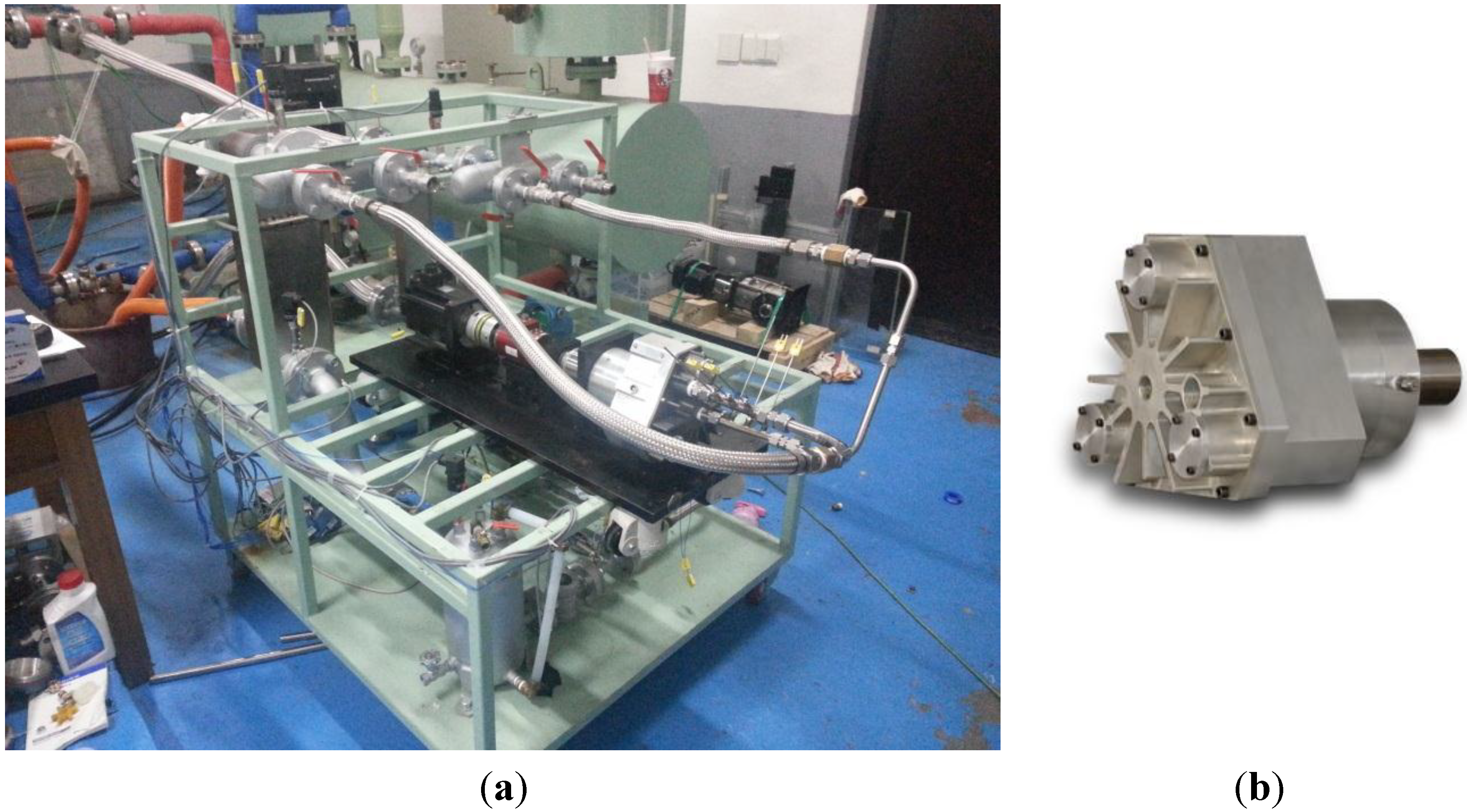
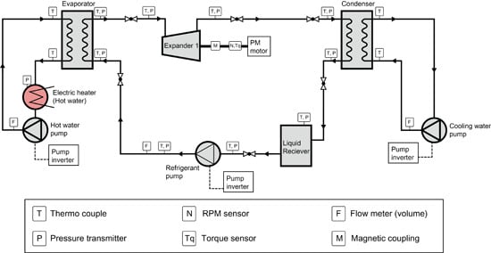
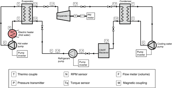
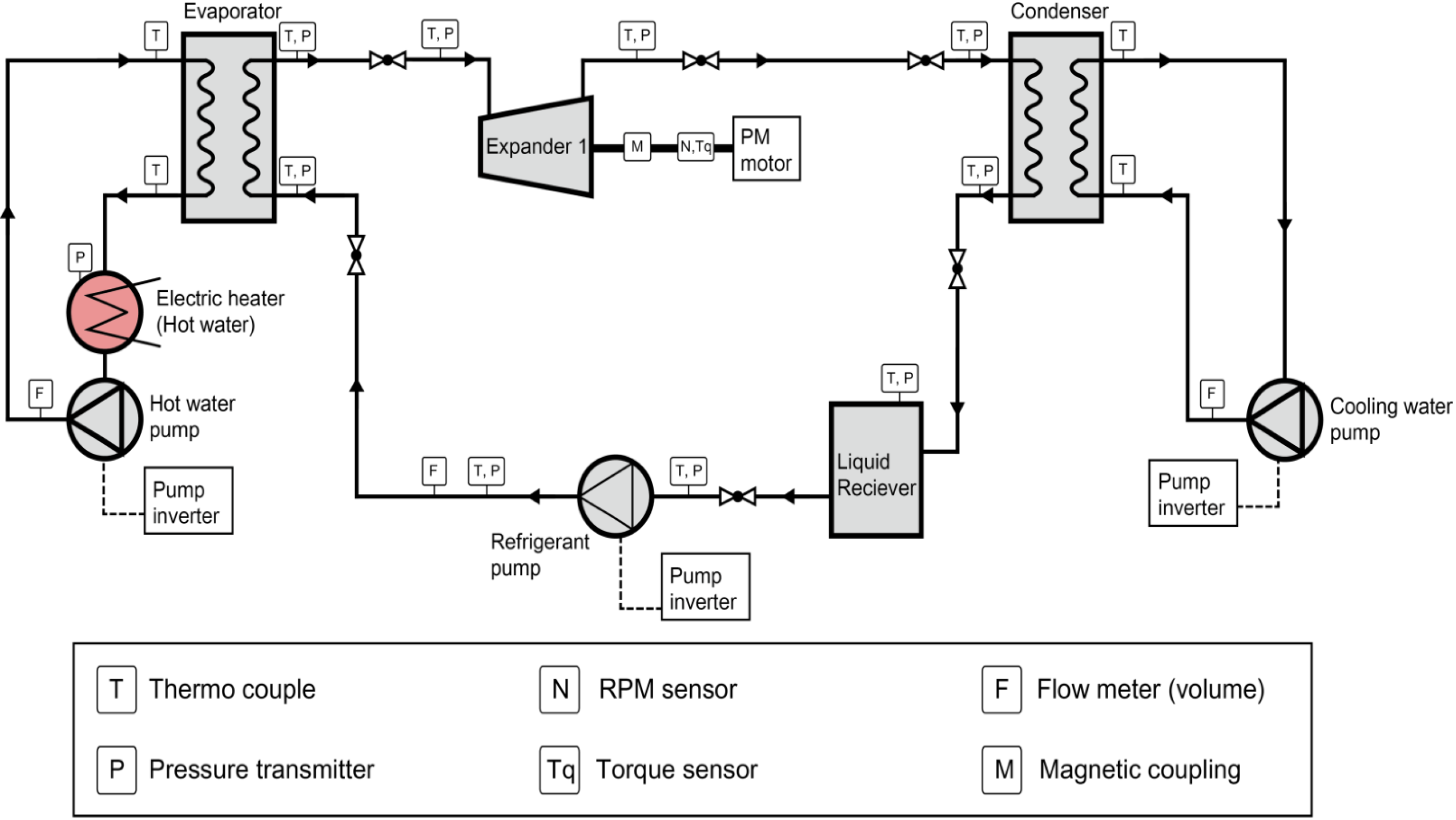
Figure 1 and
Figure 2 show the experimental setup and schematic representation of the ORC system, respectively. The refrigerant, R245fa, which is non-flammable, non-toxic with zero ozone depletion potential, was used as the working fluid for the ORC experiment. The working principle of the ORC system is as follows: The working fluid passes through the evaporator and extracts the heat from hot water (heat source), which is produced by an electric thermal heater. The working fluid in its superheated form is directed to the scroll expander for useful work. The expanded fluid after leaving the expander is cooled by cooling water operated from a chiller. The refrigerant, R245fa, which is a saturated liquid, is pumped back to the evaporator to begin its cycle. This system can be applied as a low-temperature heat source (90–130 °C), which is obtained from a solar collector. The expander used is already commercialized and the maximum rated inlet pressure is 13.5 bar. In addition, the magnetic coupling eliminates the leakage path for the working fluid allowing the scroll expander to work compatibly.
Figure 1.
Experimental setup for the small scale ORC system (a) and commercial expander (b).
Figure 1.
Experimental setup for the small scale ORC system (a) and commercial expander (b).
Figure 2.
Schematic diagram of the ORC system with its components and measuring devices.
Figure 2.
Schematic diagram of the ORC system with its components and measuring devices.
To obtain the experimental data, the electric thermal heater was allowed to heat water up to 121 °C, and then system was run for approximately 1 h under different conditions for different cases. The experiments were carried out at different rotating speeds and inlet pressures; the investigated speed range of the expander was 2400–3600 RPM and the inlet pressure range was 10–13 bar. The steady state condition was maintained for 30 min to gather data in each case. The six different cases assessed were as follows: (1) 2400 RPM in 10 bar and 13 bar; (2) 3000 RPM in 10 bar and 13 bar; and (3) 3600 RPM in 10 bar and 13 bar.
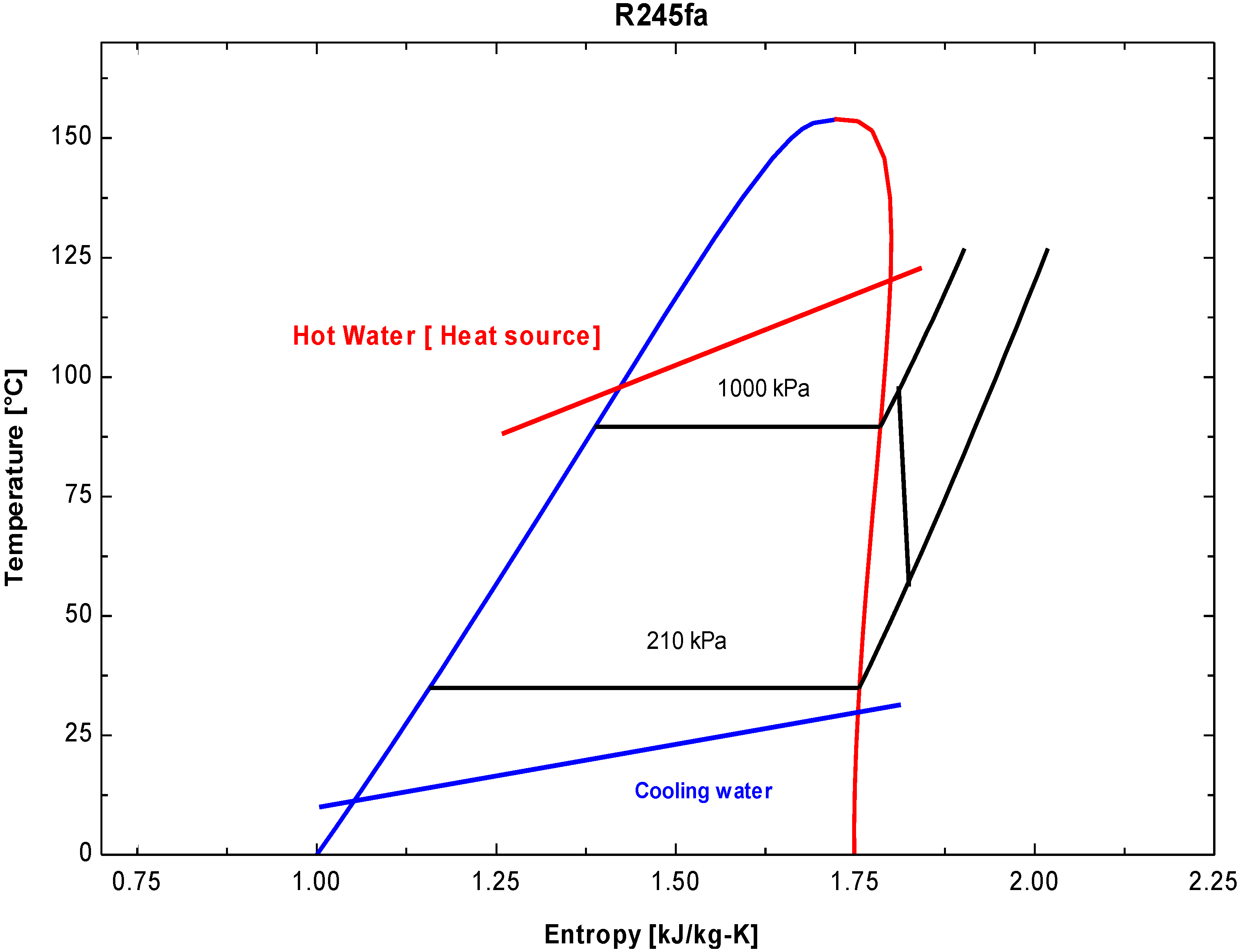
Figure 3 shows the
T–
s diagram of the organic Rankine cycle with hot water and cooling water. This diagram is for the case with a hot water temperature of 121 °C and an expander inlet pressure fixed to 10 bar. For the fixed heat source temperature, the network per unit mass of working fluid increases, as superheating of the R245fa increases. However, the maximum network per unit mass of the source has an optimal value with respect to the evaporating temperature when we are using the specific commercial expander, so we chose to superheat.
Table 2 lists the properties at different states for this condition. The dead state properties of R245fa and water were calculated at 101 kPa and 25 °C. The working fluid mass flow rate was changed by regulating the frequency of the inverter of the working fluid feed pump. The rotation of the expander was controlled using a servomotor. The torque sensor (shaft type rotary torque transducer) was used to measure the torque. Finally, the power output of the scroll expander was calculated.
Table 3 lists the measured parameters, instruments and uncertainty in measurement devices during this analysis. The temperatures and pressures under various states conditions were measured using an Omega K-type thermocouple and Sensys pressure transducer, respectively. Finally the data obtained was stored on a computer operated by a National Instruments (Austin, TX, USA) NI-cDAQ-9170, Data acquisition and control (DAQ) card.
Figure 3.
T–s diagram of R245fa, working fluid, in the ORC system.
Figure 3.
T–s diagram of R245fa, working fluid, in the ORC system.
Table 2.
Properties at each state for the ORC system.
Table 2.
Properties at each state for the ORC system.
| State No. | Fluid | Phase | Temperature (°C) | Pressure (kPa) | Density (kg/m3) | Enthalpy (kJ/kg) | Entropy (J/kg·K) |
|---|
| a | R245fa | Dead State | 25 | 101 | 5.59 | 424.63 | 1.705 |
| b | Water | Dead State | 25 | 101 | 997.05 | 104.92 | 0.370 |
| 1 | Hot Water | Compressed Liquid | 121 | 205.05 | 942.3 | 508.06 | 1.540 |
| 2 | Hot Water | Compressed Liquid | 113 | 158.44 | 948.64 | 474.12 | 1.460 |
| 3 | R245fa | Saturated Vapor | 89.54 | 1000 | 56.4 | 468.04 | 1.785 |
| 4 | R245fa | Vapor | 53 | 210 | 11.07 | 446.88 | 1.810 |
| 5 | R245fa | Saturated Liquid | 35 | 210 | 11.92 | 245.5 | 1.150 |
| 6 | R245fa | Compressed Liquid | 36 | 1000 | 1310.9 | 247.35 | 1.160 |
| 7 | Cold Water | Compressed Liquid | 26 | 195 | 996.83 | 109.19 | 0.380 |
| 8 | Cold Water | Compressed Liquid | 32 | 195 | 995.07 | 134.27 | 0.470 |
Table 3.
Parameters measured, Instrumentation and uncertainties in the measurements. FS means full scale.
Table 3.
Parameters measured, Instrumentation and uncertainties in the measurements. FS means full scale.
| Component | Parameter | State No. | Instrumentation | Unit | Uncertainty in Measurement |
|---|
| Heat Source | Hot water temperature inlet/outlet | T_1/T_2 | Omega K thermocouple | °C | ±1.1 °C |
| Hot water pressure inlet/Outlet | P_1/P_2 | Sensys pressure transducer | bar | 0.044% FS |
| Hot water Flow rate | m_h | Atozcell Turbine type | L/min | ±0.4 FS |
| Evaporator | R245fa evaporator temperature inlet/outlet | T_6/T_3 | Omega K thermocouple | °C | ±1.1 °C |
| R245fa evaporator pressure inlet/outlet | P_6/P_3 | Sensys pressure transducer | bar | 0.044% FS |
| Expander | R245fa expander temperature inlet/outlet | T_3/T-4 | Omega K thermocouple | °C | ±1.1 °C |
| R245fa expander pressure outlet or condenser inlet | P_3/P_4 | Sensys pressure transducer | bar | 0.044% FS |
| Condenser | R245fa condenser temperature inlet/outlet | T_4/T_5 | Omega K thermocouple | °C | ±1.1 °C |
| R245fa condenser pressure inlet/outlet | P_4/P_5 | Sensys pressure transducer | bar | 0.044% FS |
| Pump | R245fa pump temperature inlet/outlet | T_5/T_6 | Omega K thermocouple | °C | ±1.1 °C |
| R245fa pump temperature inlet/outlet | P_5/P_6 | Sensys pressure transducer | bar | 0.044% FS |
| Heat Sink | Cold water temperature inlet/outlet | T_7/T_8 | Omega K thermocouple | °C | ±1.1 °C |
| Cold water pressure inlet/outlet | P_7/P_8 | Sensys pressure transducer | bar | 0.044% FS |
| Servomotor | RPM controller | N/A | HIGEN FMACN30-AB00 | kW | ±0.25% FS |
| Torque transducer | Shaft Type Rotary Toque Transducer | N/A | Model CTR-5KM | kgf-m | ±0.1 FS |
3. Thermodynamic System Models: Energy and Exergy Analysis
The pre-described ORC system was simulated by developing the code using the Engineering Equation Solver (EES). The following assumptions were made when analyzing the sub-system and overall system:
- (a)
All the thermodynamic processes that involve sub-systems are in the steady state.
- (b)
The pumps and scroll expander are adiabatic devices.
- (c)
The pressure drops in the evaporator and condenser can be neglected because negligible pressure occurs in any of the ORC devices.
- (d)
The dead state temperature and pressure are 25 °C and 1 bar (atmospheric pressure) respectively.
The general expressions for the energy balances of any steady state that is applied in each of the system components can be expressed as:
where subscripts in and out represent the inlet and outlet, respectively;
and
h represent the mass flow rate and specific enthalpy, respectively, of the streams of the system working fluid; and
and
represent the heat transfer and work transfer crossing the component boundaries, respectively.
Exergy analysis is a thermodynamic analysis technique based on the second law of thermodynamics that is used to evaluate and compare processes and systems implicitly [
24]. Exergy analysis yields the efficiency, which is a true measure of how close the actual performance approaches the ideal, and identifies the causes and locations of thermodynamic losses more clearly than energy analysis [
24]. This is the maximum theoretically useful work that can be obtained from the system when it interacts to equilibrium with the surrounding environment. The exergy destruction in each component can be estimated by applying the exergy balance on the systems components at the steady state which can be given by following expression:
where
represents the irreversibility rate that occurs at the device,
is the exergy rate. The specific flow exergy is given by
and the exergy rate is:
The exergy transfer due to heat and work can be expressed as:
where
T0 is the dead state temperature that describes the state at which the system is in equilibrium with the environment and
T is the boundary temperature at which heat transfer occurs.
Heat and exergy balance in an evaporator and condenser:
where
and
are the irreversibilities in the evaporator and condenser, respectively. The exergy efficiency of the evaporator and condenser can be expressed as:
The energy conservation, exergy balance and exergy efficiency of the expander is defined by the following equations:
In addition, the energy conservation, exergy balance and exergy efficiency of the pump is defined by the following equations:
The net work done by the system can be given by following expression:
The overall system thermodynamic performance can be measured by the energy and exergy efficiencies. The energy efficiency of the simple ORC system can be expressed as:
The exergy efficiency is defined as the useful exergy output of the system, which is the net work done over the exergy of the utilized input to the system.
The overall exergy efficiency of the ORC system can be written as:
The total exergy destruction in the cycle is the sum of all the components of the exergy destruction, which can be written as:
Furthermore, the sustainability dimension of the ORC system was assessed. Sustainable development requires the efficient use of the available resources besides the clean and affordable energy resources. Therefore, a simple assessment can be possible through the sustainability index (SI), which is defined as a function of the exergy efficiency [
24]. In other words, it is means of measuring the sustainability of the exergy-based system and processes that represent a true measure of imperfections. This indicates the possible ways to improve energy systems and to design better ones. A higher sustainability index shows better sustainability of the system:
where
TH and
TC are heat source (hot water) and heat sink (cold water) temperatures respectively.
4. Results and Discussion
A complete and thorough thermodynamic analysis based on the first and second laws of thermodynamics were performed on the ORC system. The energy, exergy and working fluid mass flow rate balance equations were applied to the system components under steady state operation. The calculations of the working fluid mass flow rate of the refrigerant, R245fa, the corresponding hot water fluid and cooling water were calculated. The ORC extracted, 12.5 kW, of the heat from the hot water to produce 0.95 kW of net power output when the expander inlet pressure was 1000 kPa. The corresponding the pressure ratio was 5.8.
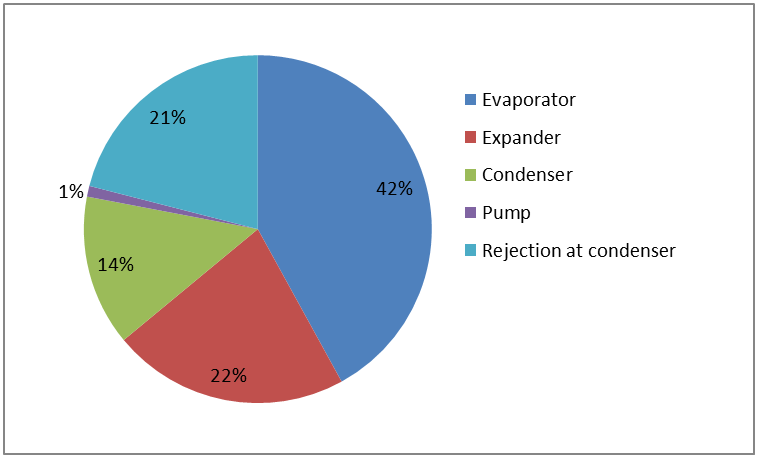
Figure 4 shows the exergy destruction percentage for different components in the ORC. The highest exergy destruction occurred in an evaporator of the ORC system during the heat exchange process followed by the expander, condenser and working fluid feed pump. The total exergy destruction in the system was 1.12 kW. Similarly, the exergy efficiency for the evaporator, expander, condenser and pump were 75%, 80%, 43.2% and 80.78%, respectively. In addition, the overall thermal efficiency and exergy efficiency were 7.54% and 43.73%, respectively.
Improvement potential is an indicator of possible improvement in the small scale ORC system from an exergetic point of view. Based on the exergy destruction percentage as indicated in
Figure 4, it can be easily used to locate where the maximum exergy is destroyed. This helps in focusing the improvements in the system components and improving the overall energy efficiency of the ORC system. The main source of exergy destruction is the evaporator, which accounts for 42% of the total exergy destroyed in the system. The exergy is destroyed in the evaporator due to the temperature difference between the incoming and leaving hot water in the component. Therefore further improvement can be attained by careful design of the evaporator, which would require large heat exchange surface area. This improvement opportunity for evaporator can significantly improve the efficiency of the ORC system. On the other hand, exergy lost in the expander accounts for 22% of the total exergy destroyed in the system. It is due to the expander’s internal performance. Therefore, the task of reducing exergy destruction or improving the efficiency of the scroll expander is very specialized. The detailed geometrical description of the scroll expander with thermodynamic modelling of the expansion process is needed to improve the exergy lost. Similarly, it has been observed that there is 14% of exergy destroyed in the condenser. This indicates that thermal energy in the condenser does not have much potential to be utilized in the ORC system. Finally the pump has negligible amount of exergy destruction in the system and need not to be improved. It is noted that there are still opportunities to improve energy efficiency of the small-scale ORC system by improving the performance of evaporator and scroll expander.
Figure 4.
Exergy destruction percentage in the ORC system components.
Figure 4.
Exergy destruction percentage in the ORC system components.
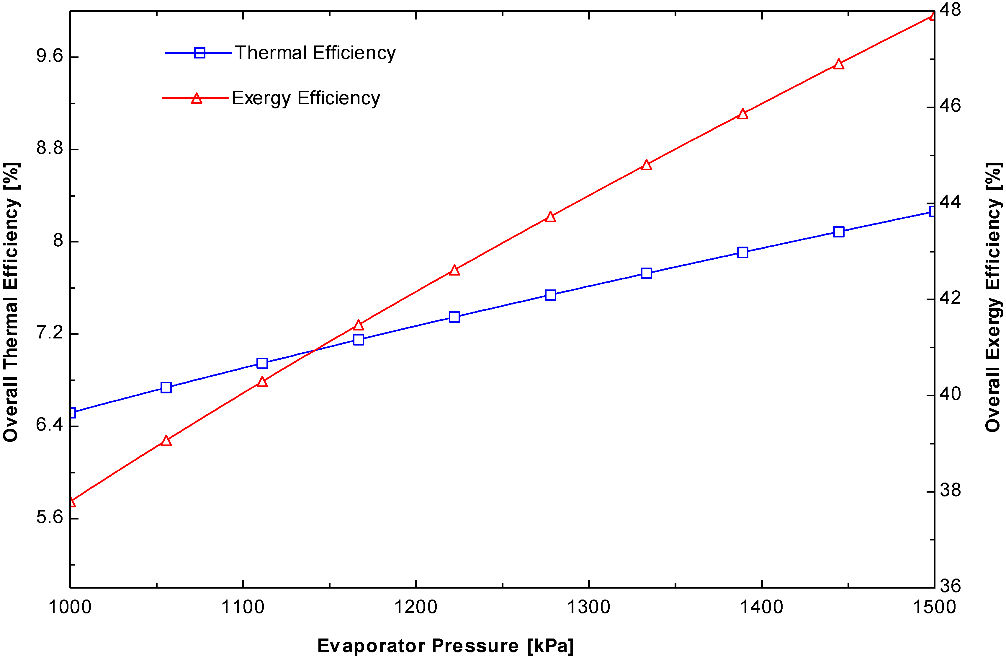
Figure 5.
Variation of the thermal and exergy efficiencies of the cycle as a function of the evaporation pressure.
Figure 5.
Variation of the thermal and exergy efficiencies of the cycle as a function of the evaporation pressure.
Figure 5 shows the variations of the thermal and exergy efficiencies when the evaporator pressure was changed from 1000 to 1500 kPa. These indicate that both efficiencies increase by 26.78% when there is an increase in the evaporator pressure in the ORC system. A higher evaporator pressure increases both the specific net work done and the specific evaporator heat input. On the other hand, the percentage increase in the net work done is higher than the increase in the evaporator heat rate, which leads to an improvement in the energy efficiency.
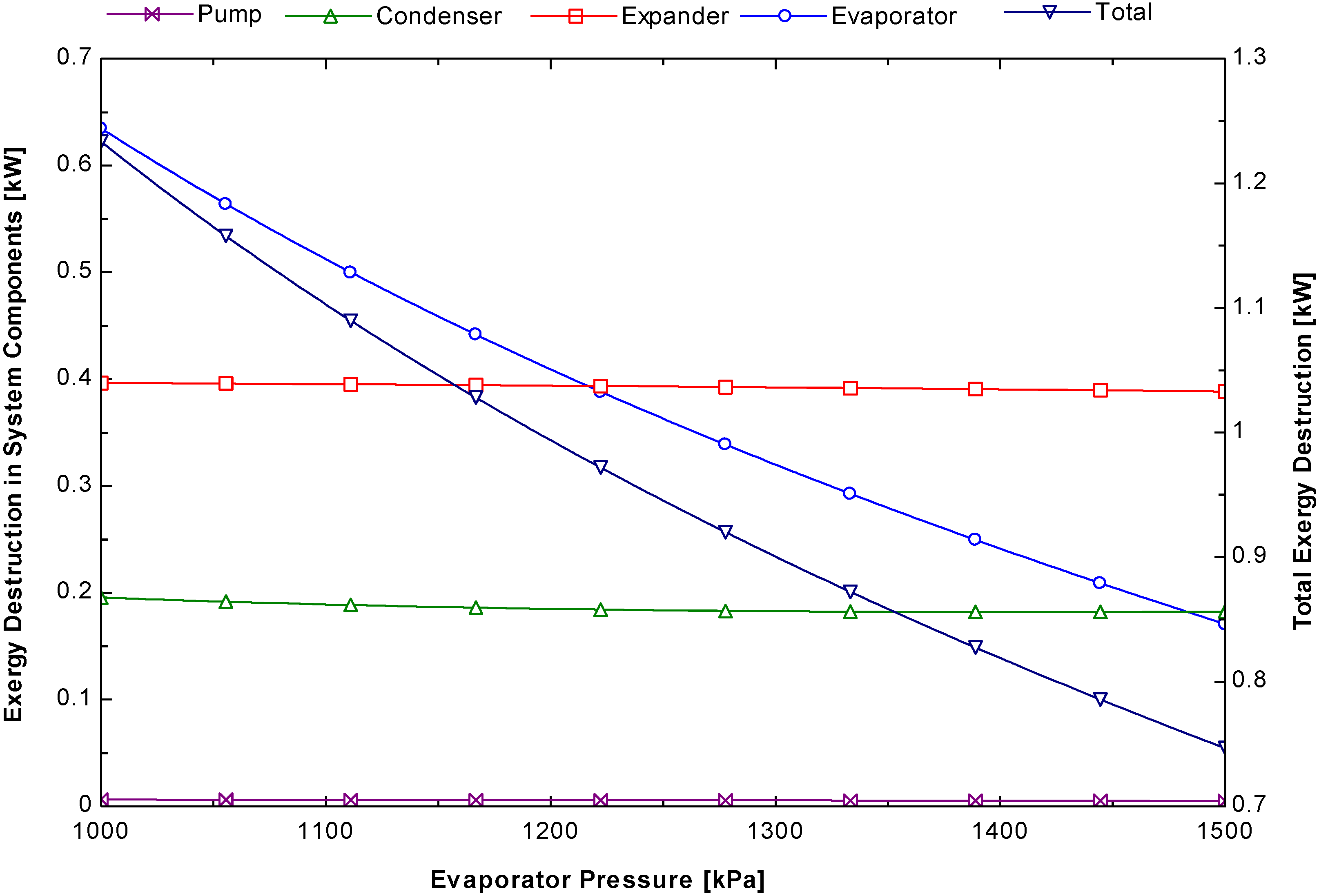
Figure 6 shows that the exergy destruction increases slightly for the expander, condenser and pump but exergy destruction decreases dramatically in the evaporator when the evaporator pressure changes. This is because of the difference in temperature of the hot water entering in evaporator and leaving out from it. This decrease in temperature difference leads to an improvement in exergy efficiency.
Figure 6.
Variation of the system components and total exergy destruction as a function of the evaporation pressure.
Figure 6.
Variation of the system components and total exergy destruction as a function of the evaporation pressure.
The commercial expander has the pressure limit up to 13.5 bar, the simulation has been carried out up to 15 bar. This helps in knowing how much difference could be obtained in the exergy and system’s energy efficiency and exergy destruction in the components when the operating pressure goes beyond the 13.5 bar. It is seen from the simulation that not much difference in efficiencies can be reached in raising the pressure by 2 bar greater than the limited value. However, raising system pressure is not always feasible due to capital costs, system complexity and materials properties of scroll expander.
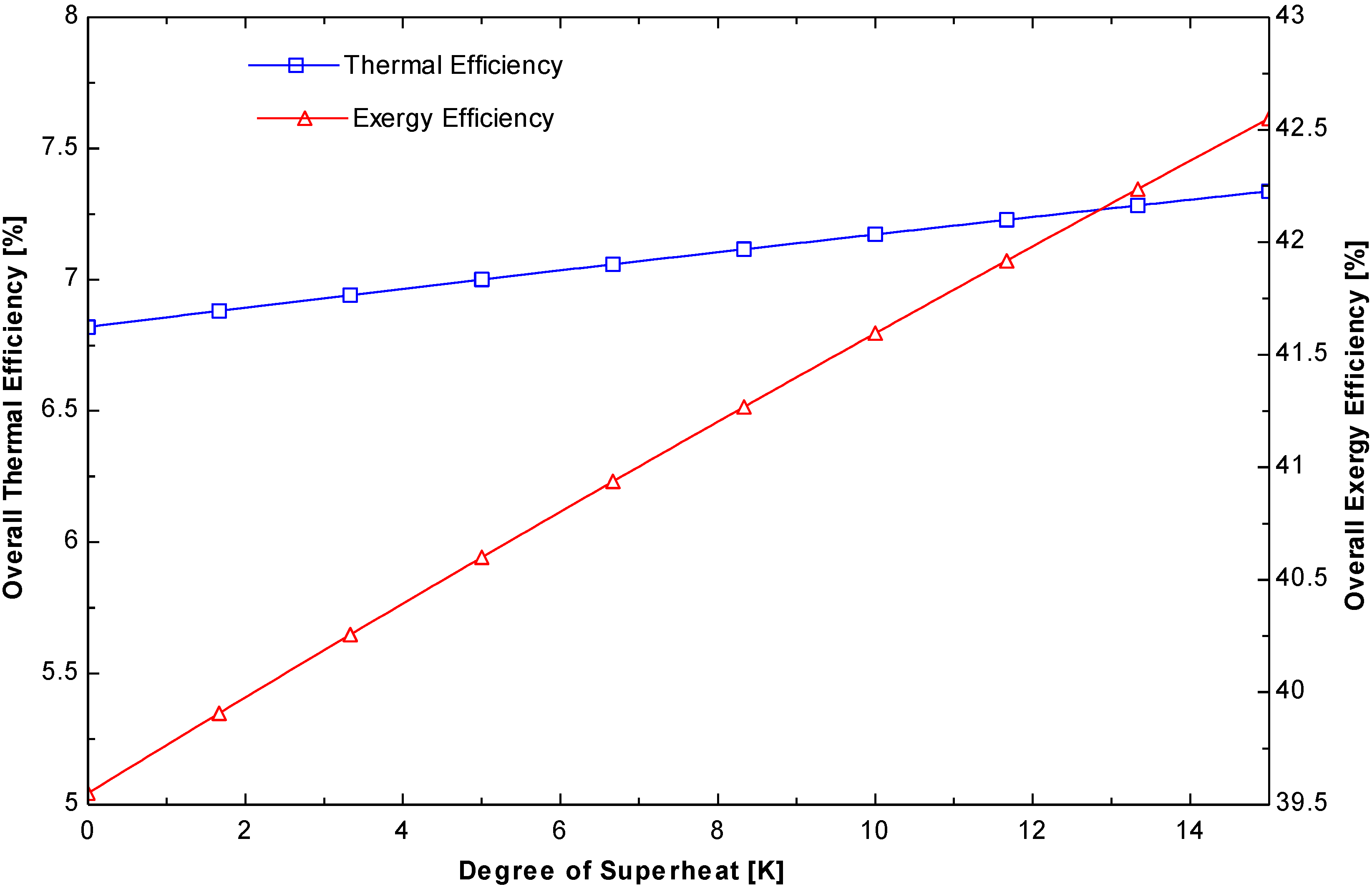
Figure 7 shows the effect of the degree of superheating on the energy and exergy efficiencies of the ORC system. These efficiencies increase gradually with increasing degree of superheating. When the degree of superheating is 15 °C, the energy and exergy reach their maximum efficiencies of 7.33% and 42.55%, respectively. This increase in efficiency is due to a change in enthalpy at different states, which determines the performance of the ORC system.
Figure 7.
Variation of the thermal and exergy efficiencies of the cycle as a function of the degree of superheating at a constant evaporation pressure.
Figure 7.
Variation of the thermal and exergy efficiencies of the cycle as a function of the degree of superheating at a constant evaporation pressure.
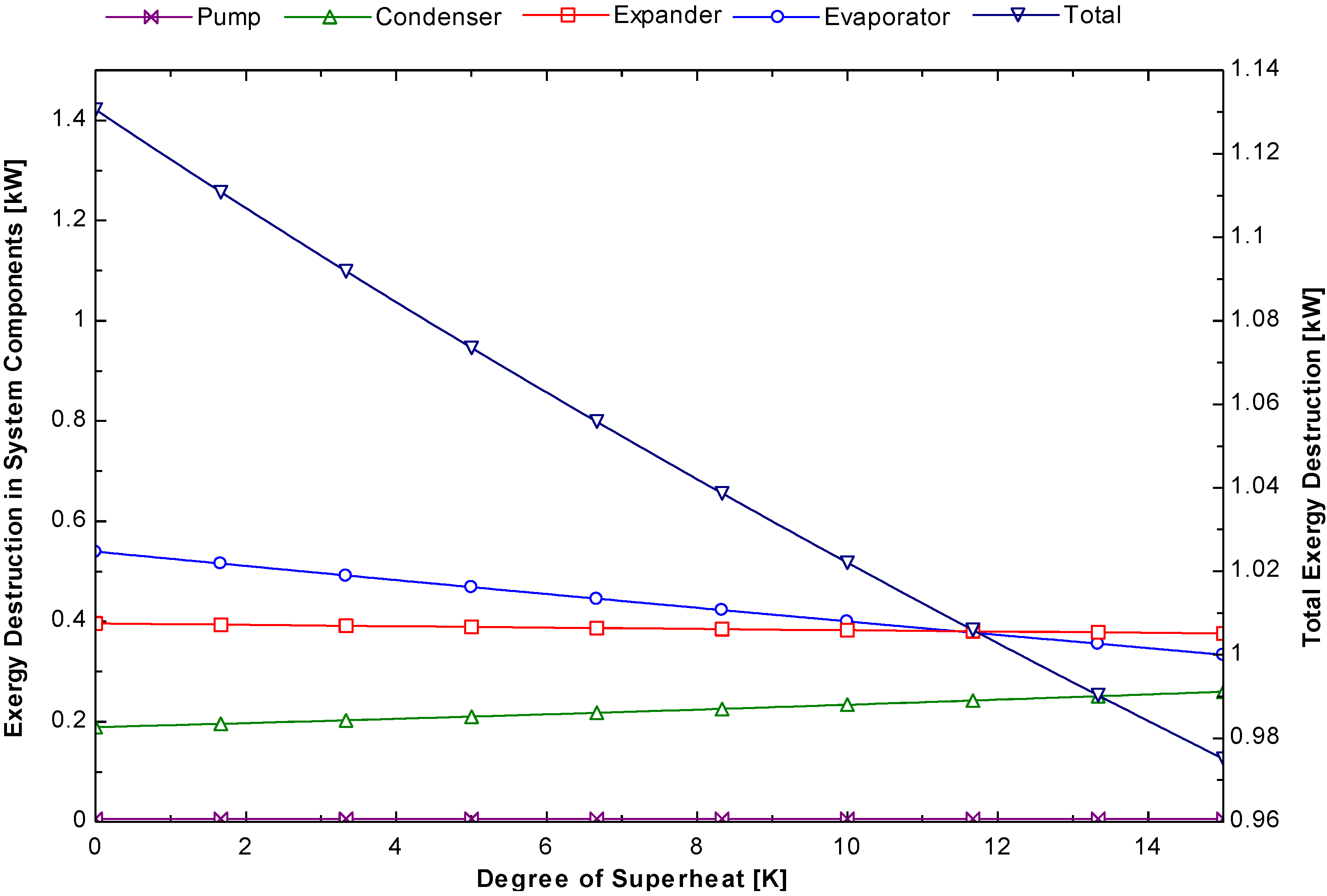
Figure 8 shows the variation of the system components exergy destruction for different degrees of superheat temperatures at the evaporator outlet for a constant evaporator pressure. Significantly less change in exergy destruction was observed when the working fluid of the system is superheated. The above simulation shows that increasing the degree superheating is beneficial for improving the exergy efficiency of the system.
Figure 8.
Variation of the exergy destruction of the system components as a function of the degree of superheating.
Figure 8.
Variation of the exergy destruction of the system components as a function of the degree of superheating.
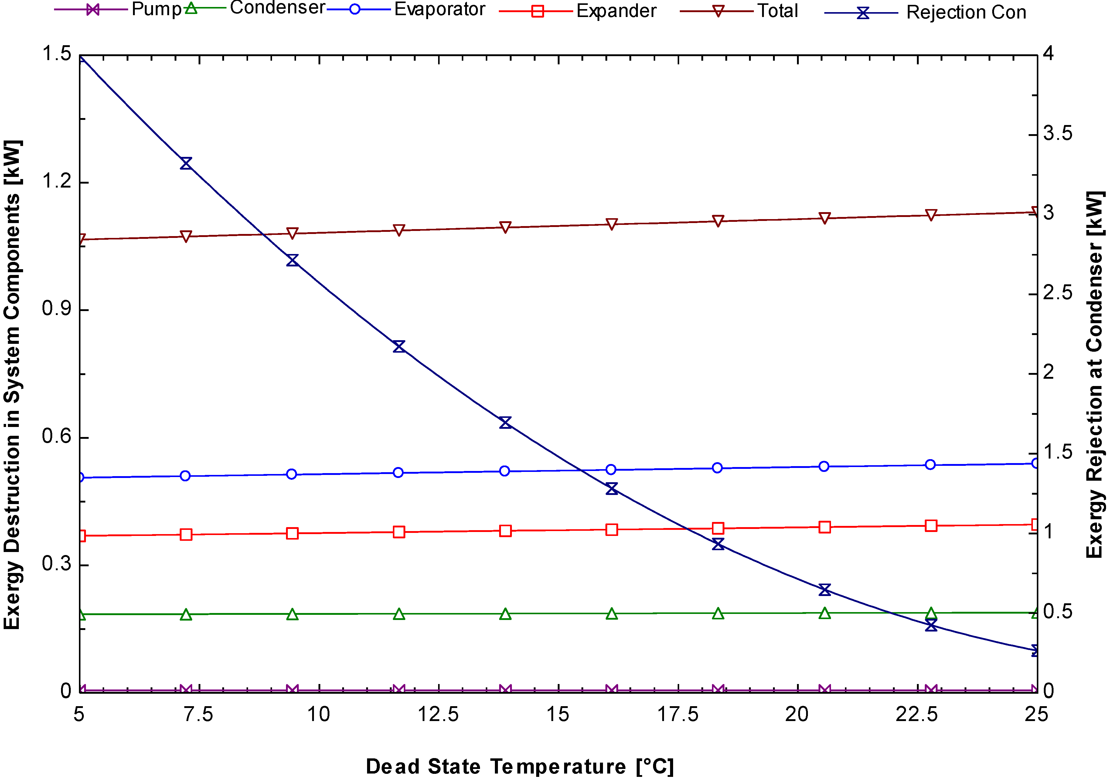
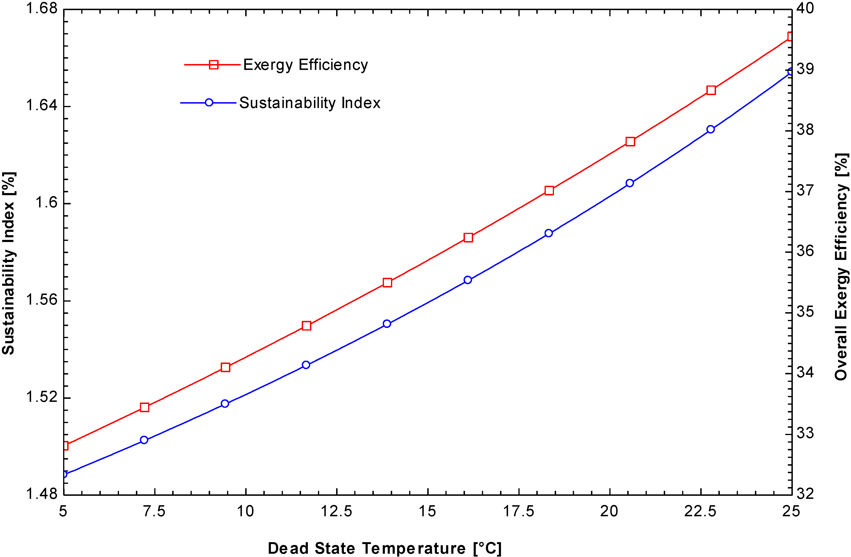
Figure 9 shows the variation of the sustainability index and exergy efficiency as a function of the dead state temperature. This figure shows that both parameters have the same trend in the overall performance of the ORC system. The maximum value of the sustainability index was 1.67, whereas the exergy efficiency is close to 40% when the dead state temperature changes from 5 to 25 °C.
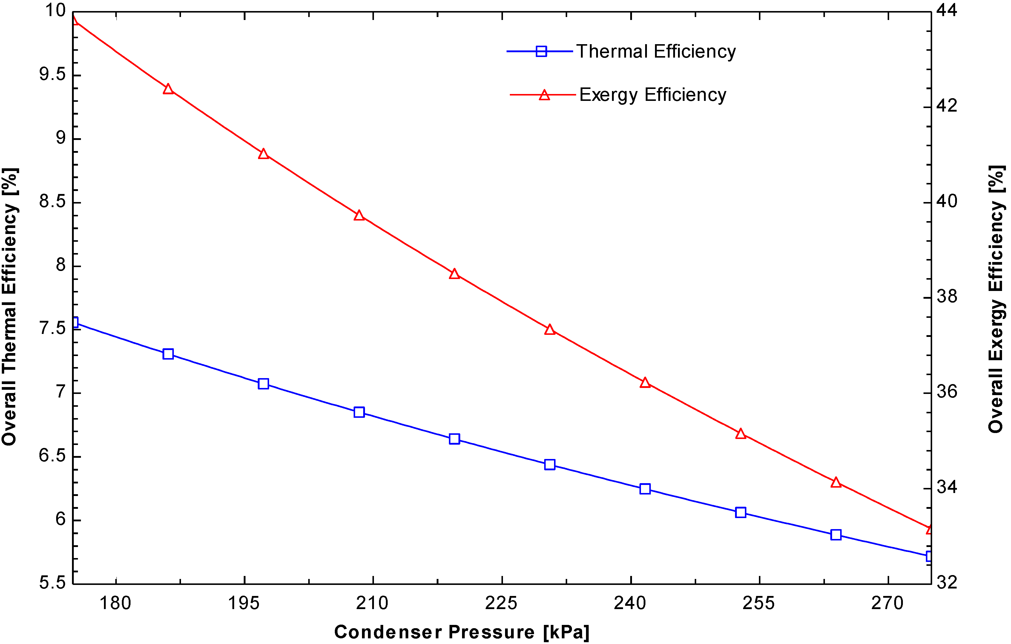
Figure 10 shows the total exergy destruction of the evaporator, expander, condenser, and pump increase slightly when the dead state temperature is increased. The same figure shows that the rate of exergy transfer from the working fluid to the condenser cooling water is reduced dramatically and that heat transfer is responsible for the higher exergy efficiency in the overall ORC system. The condensing pressure in the ORC system has a significant impact on the system performance. This determines the overall heat rejection temperature, which is another key parameter for improving the cycle efficiency besides the heat input temperature. The lower the condensing pressure, the higher the overall energy and exergy efficiencies.
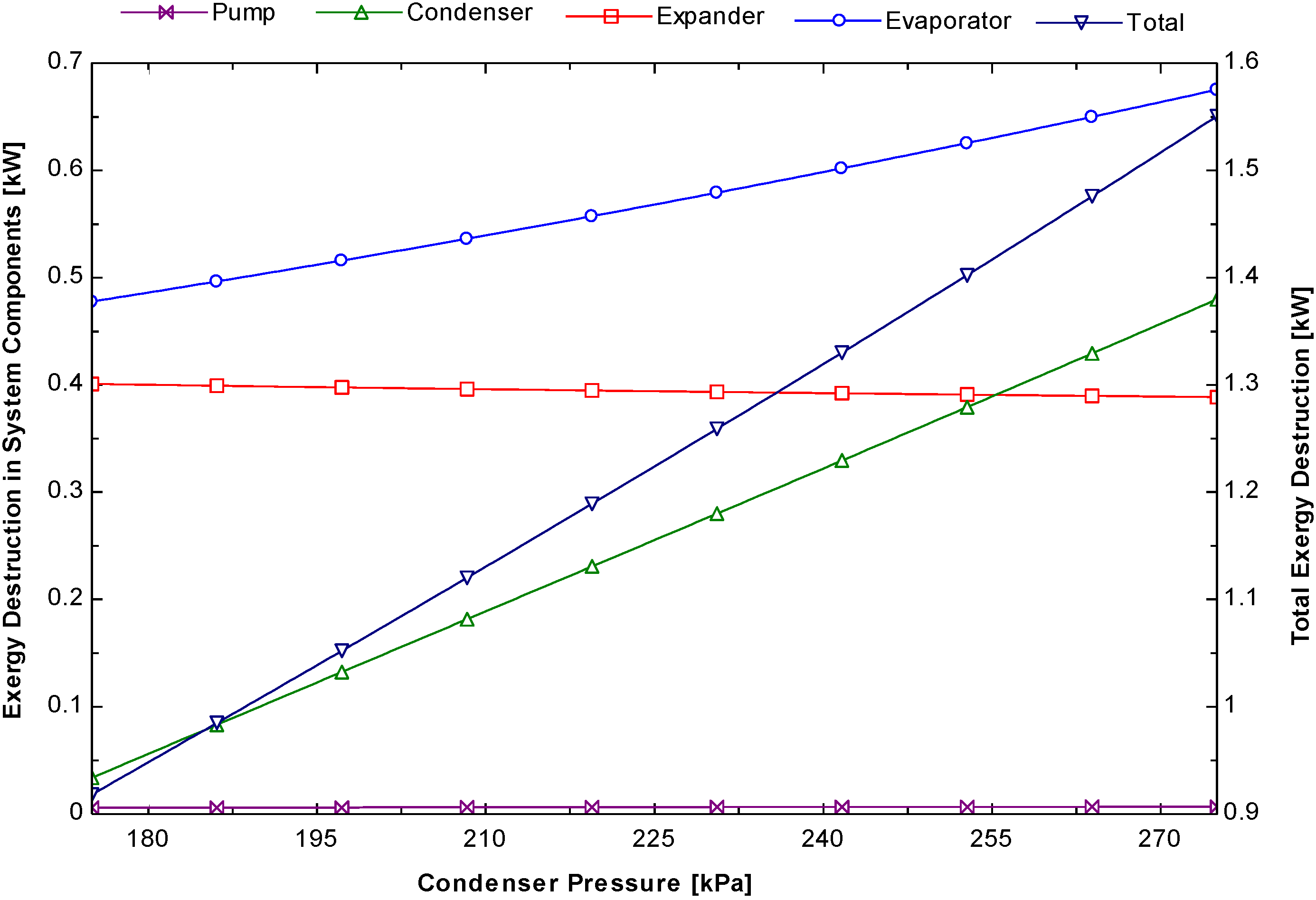
Figure 11 shows the same trend as that described above. At a condenser pressure (175 kPa) with both isentropic efficiencies of the expander and pump kept constant, the energy and exergy efficiencies were 7.5% and 43.8%, respectively. Both the energy and exergy efficiencies decreased with increasing condenser pressure because there is a rise in the exergy destruction in the condenser. The decrease in energy efficiency was also due to a lower enthalpy drop in the expander.
Figure 12 shows the exergy destruction in different components of the system. The figure shows that exergy destruction in the condenser increases with increasing condenser pressure. The exergy destruction in the condenser at 175 kPa and 275 kPa were 0.08 kW and 0.65 kW, respectively. No exergy destruction effect was observed on the expander and pump but the evaporator was affected.
Figure 9.
Variation of the sustainability index and exergy efficiency as a function of the dead state temperature.
Figure 9.
Variation of the sustainability index and exergy efficiency as a function of the dead state temperature.
Figure 10.
Variation of system components exergy destruction and exergy rejection to condenser cooling water as a function of the dead state temperature.
Figure 10.
Variation of system components exergy destruction and exergy rejection to condenser cooling water as a function of the dead state temperature.
Figure 11.
Variation of the thermal and exergy efficiency of the cycle as a function of the condensation pressure.
Figure 11.
Variation of the thermal and exergy efficiency of the cycle as a function of the condensation pressure.
Figure 12.
Variation of system components and total exergy destruction as a function of the condensation pressure.
Figure 12.
Variation of system components and total exergy destruction as a function of the condensation pressure.
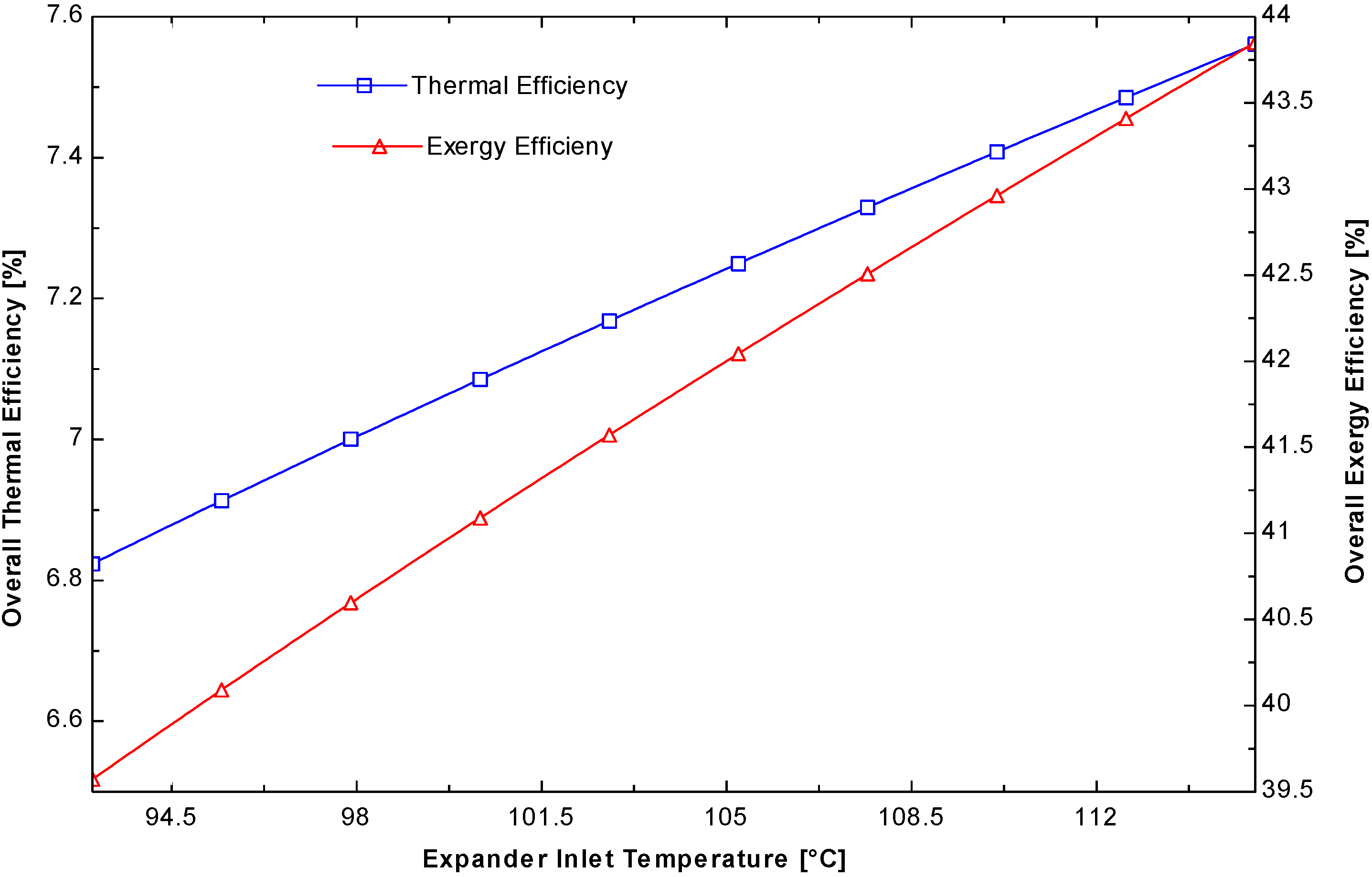
As shown in
Figure 13, for the working fluid, R245fa, the system energy and exergy efficiencies increased with increasing expander inlet temperature predictably. The variation trends of the energy and exergy efficiencies were similar. At the expander inlet temperature, ranging from 94 to 115 °C, the energy efficiencies ranged from 6.5% to 6.8%, whereas the exergy efficiencies ranged from 39.6% to 43.8%, respectively. This is the increment efficiency up to 10.8% in both cases. Owing to a change in the state conditions of the working fluid, the enthalpy changes, so there is an increase in efficiency.
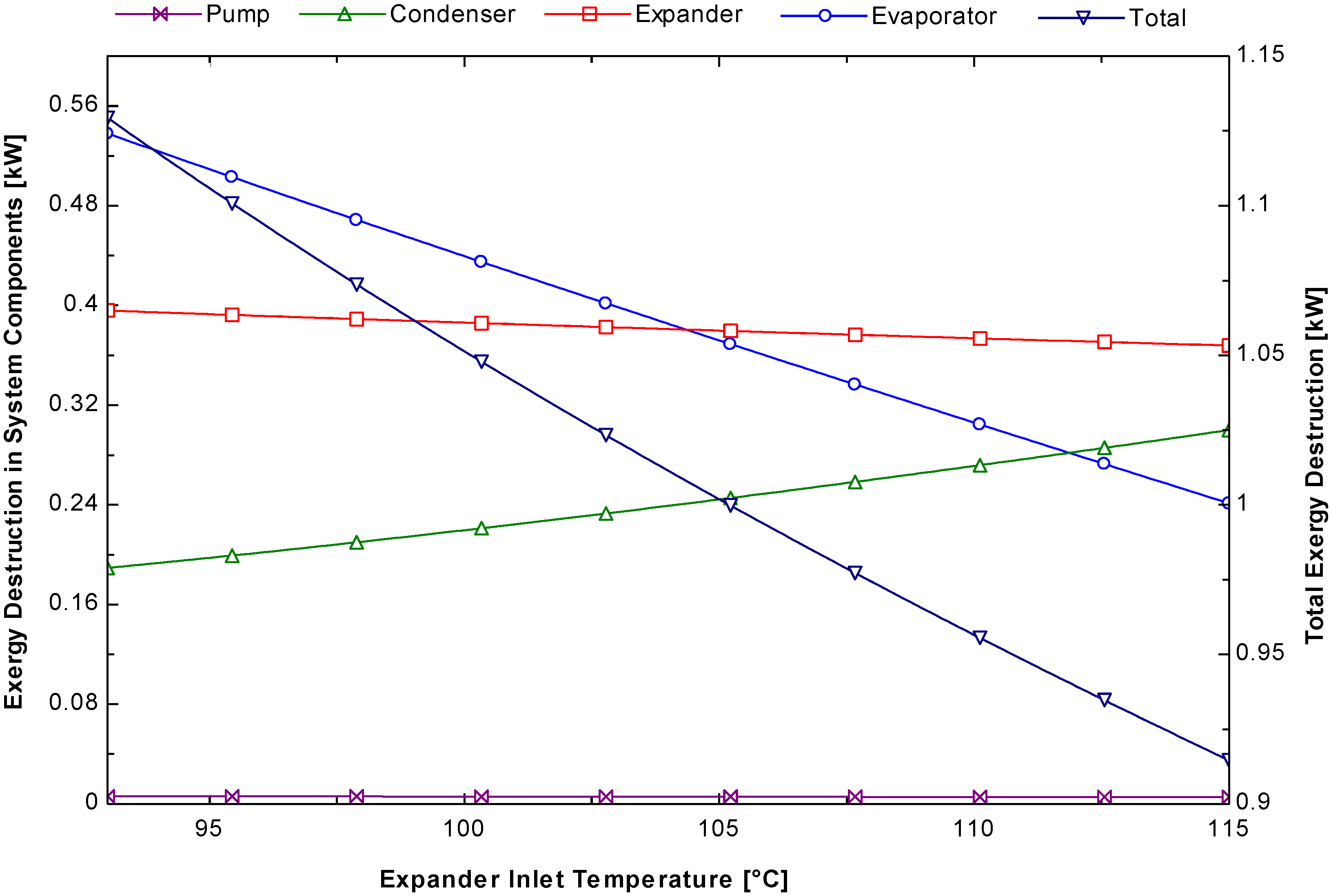
Figure 14 shows the effect of exergy destruction in the system components when the expander inlet temperature varies. Exergy destruction in the expander decreased with increasing expander temperature but the condenser exergy increased slightly.
Figure 13.
Variation of the thermal and exergy efficiencies of the cycle with the expander inlet temperature.
Figure 13.
Variation of the thermal and exergy efficiencies of the cycle with the expander inlet temperature.
Figure 14.
Variation of the system components and total exergy destruction with the expander inlet temperature.
Figure 14.
Variation of the system components and total exergy destruction with the expander inlet temperature.
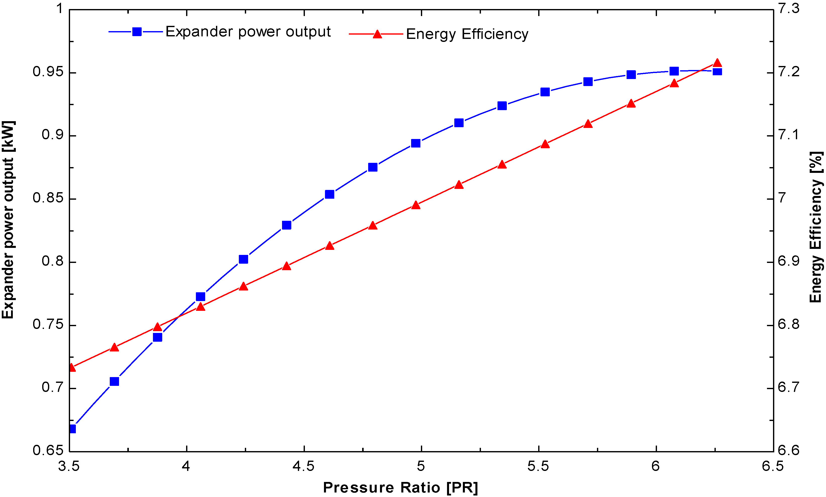
The pressure ratio plays an important role in the ORC system; the higher the pressure ratio, the greater the power developed.
Figure 15 shows that the expander output power increased from 0.68 to 0.95 kW as the pressure ratio was increased from 3.5 to 6. The maximum pressure ratio was 5.9 when the evaporator temperature was 1000 kPa. In addition, in the same figure, the energy efficiency increased from 6.7% to 7.2%.
Figure 15.
Variation of the expander power output and energy efficiency of the cycle with pressure ratio.
Figure 15.
Variation of the expander power output and energy efficiency of the cycle with pressure ratio.
5. Experimental Analysis of Small-Scale ORC System
To identify the optimal operating parameters for a small scale ORC system, a test bench was realized to test the expander for different inlet pressures, working fluid mass flow rates and rotational speeds. The aim of the experiment was to determine the highest energy performance that can be used in rural areas of un-electrified countries with minimum maintenance. The highest maximum operating pressure, isentropic efficiency and power output of the scroll expander are the main parameters that need to be established before installing this small-scale ORC system in a particular location of a developing country. A different series of experimental tests was performed to measure the previously described parameters.
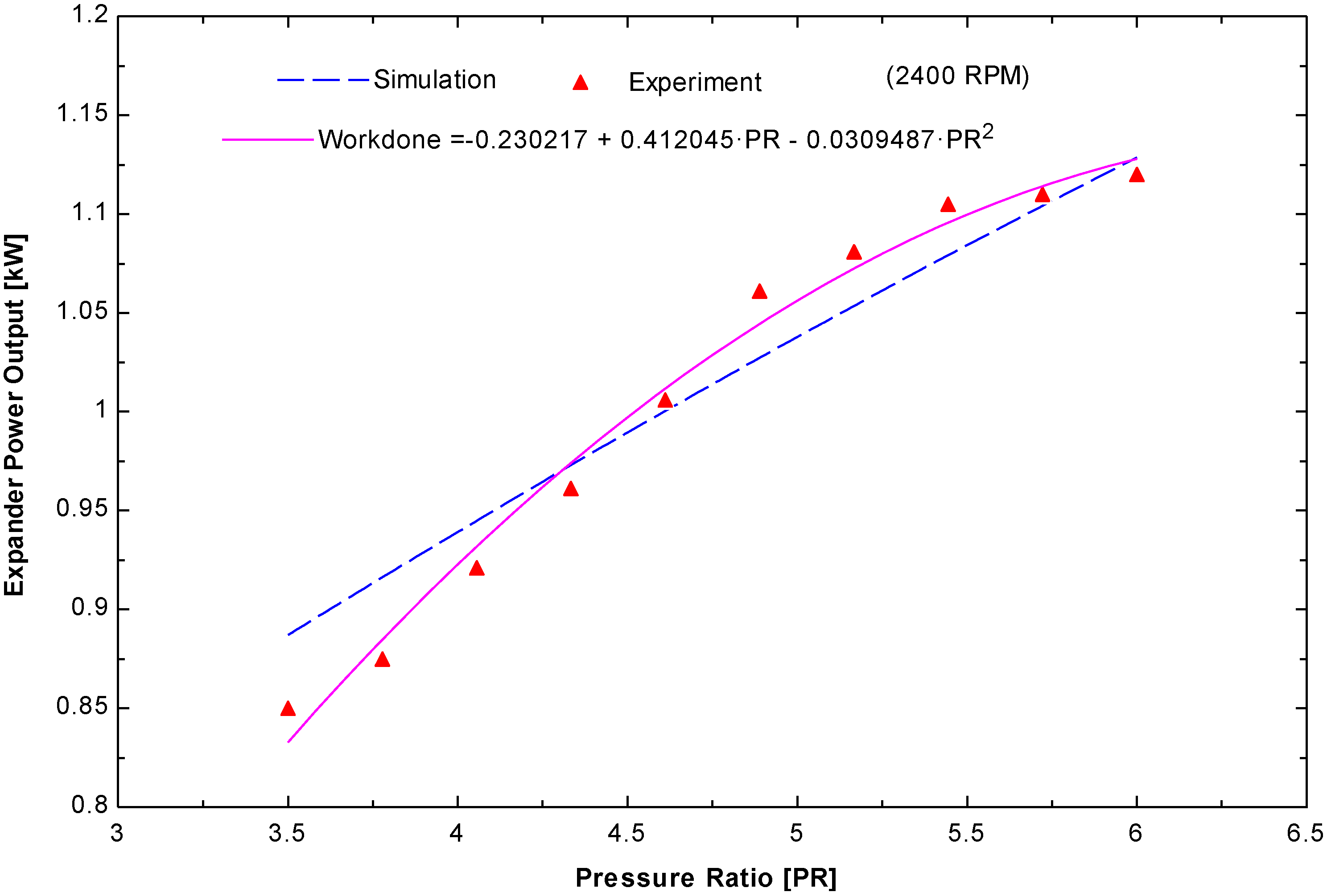
To validate the thermodynamic model, the simulated and experimental results were compared. As shown in
Figure 16, there was very good agreement between the expander power output (simulated) and produced gross power output (experimental) from the small scale ORC system that adopt scroll expander. Therefore, this close agreement suggests that the assumptions considered when calculating the parameter were valid. The maximum relative error was less than 4.3% for this system, which uses R245fa as the working fluid. This also suggests that the simulation will be valid for all different cases used in the experiments to identify the operating parameters. A maximum expander power output of 1.2 kW was obtained using a hot water entry temperature of 121 °C and a pressure ratio of 5.8 when running the expander at 2400 RPM and 13 bar.
Figure 16.
Comparison of the simulated and experimental results for the expander power output as a function of the pressure ratio.
Figure 16.
Comparison of the simulated and experimental results for the expander power output as a function of the pressure ratio.
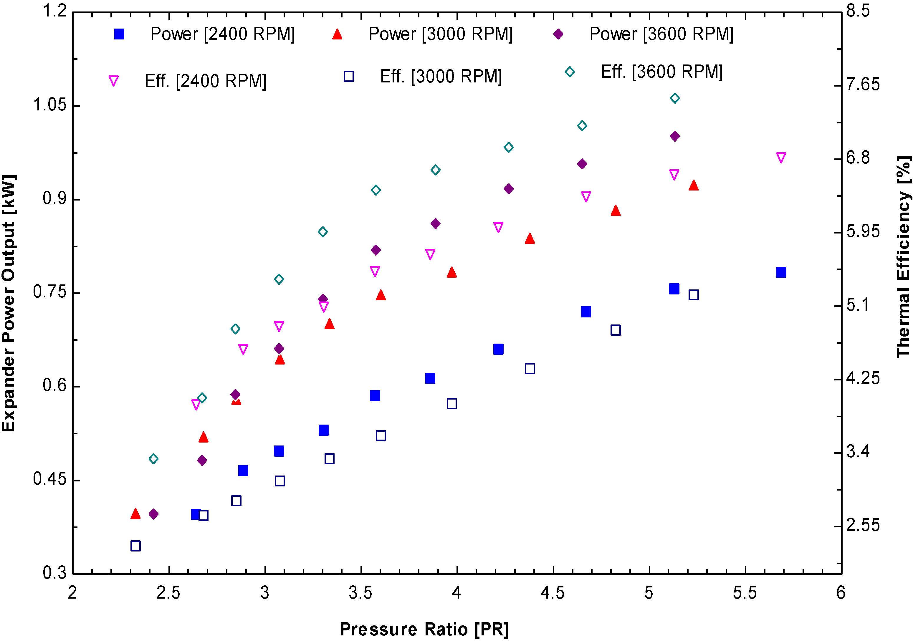
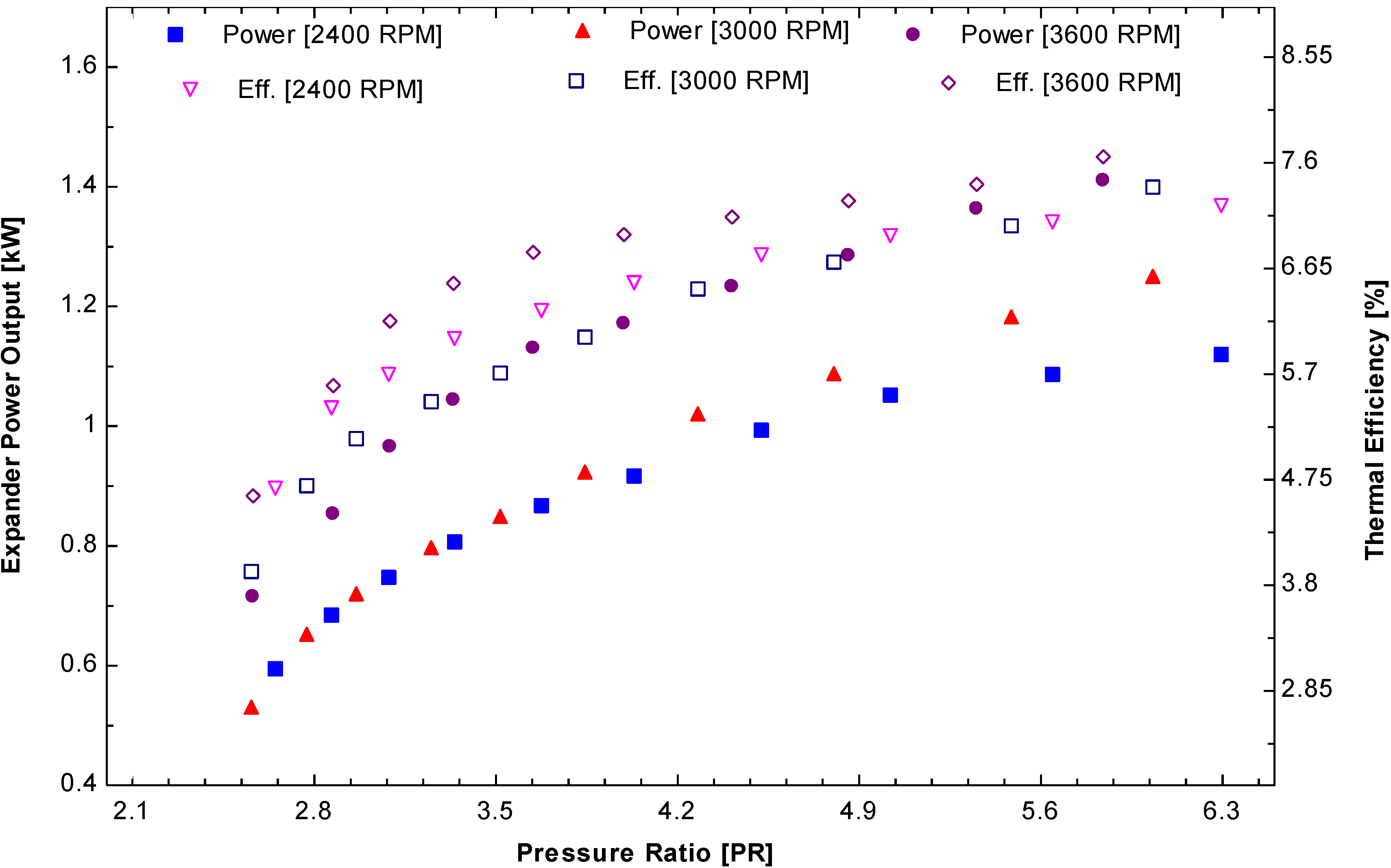
Figure 17 and
Figure 18 show the expander power output and thermal efficiencies for different sets of experiments (2400 RPM: 10/13 bar; 3000 RPM: 10/13 bar; 3600 RPM: 10/13 bar). The experimental results indicate that the maximum power output (1.4 kW) can be obtained from the 3600 RPM and 13 bar inlet pressure. The corresponding thermal efficiency was 8.55% at the rotational speed of the expander.
Figure 17.
Performance parameters: Scroll expander power output and thermal efficiency as a function of pressure ratio at different rotational speeds (10 bar).
Figure 17.
Performance parameters: Scroll expander power output and thermal efficiency as a function of pressure ratio at different rotational speeds (10 bar).
Figure 18.
Performance parameters: Scroll expander power output and thermal efficiency as a function of pressure ratio at different rotational speeds (13 bar).
Figure 18.
Performance parameters: Scroll expander power output and thermal efficiency as a function of pressure ratio at different rotational speeds (13 bar).
The trends for all cases were the same with different rotational speeds of the expander, which demonstrates a higher pressure ratio yield higher power and thermal efficiency. From the experiment, the thermal efficiency of the ORC system increases slightly with increasing rotational speed of the expander but the increase in power output was quite high compared to the expander running from 2400 to 3600 RPM with the same inlet pressure.
It is crucial to investigate the isentropic efficiency of the expander for this small-scale ORC system. This isentropic efficiency of scroll expander helps in determining the total power output of the ORC system. The isentropic efficiency of expander needs to be determined.
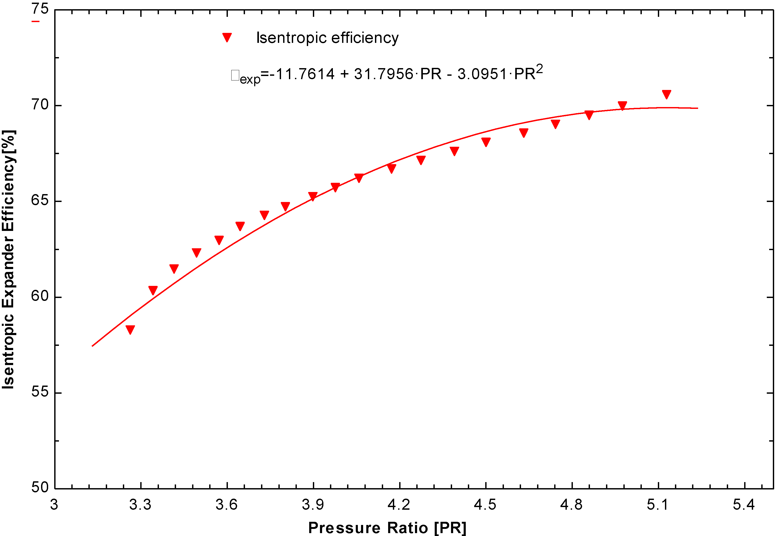
Figure 19 shows that the isentropic efficiency of the scroll expander reached a maximum of 70% when the ORC system was operated at 3600 RPM with an inlet pressure of 13 bar.
Figure 19.
Performance parameters: Scroll expander isentropic efficiency as a function of the pressure ratio (2400 RPM/10 bar).
Figure 19.
Performance parameters: Scroll expander isentropic efficiency as a function of the pressure ratio (2400 RPM/10 bar).
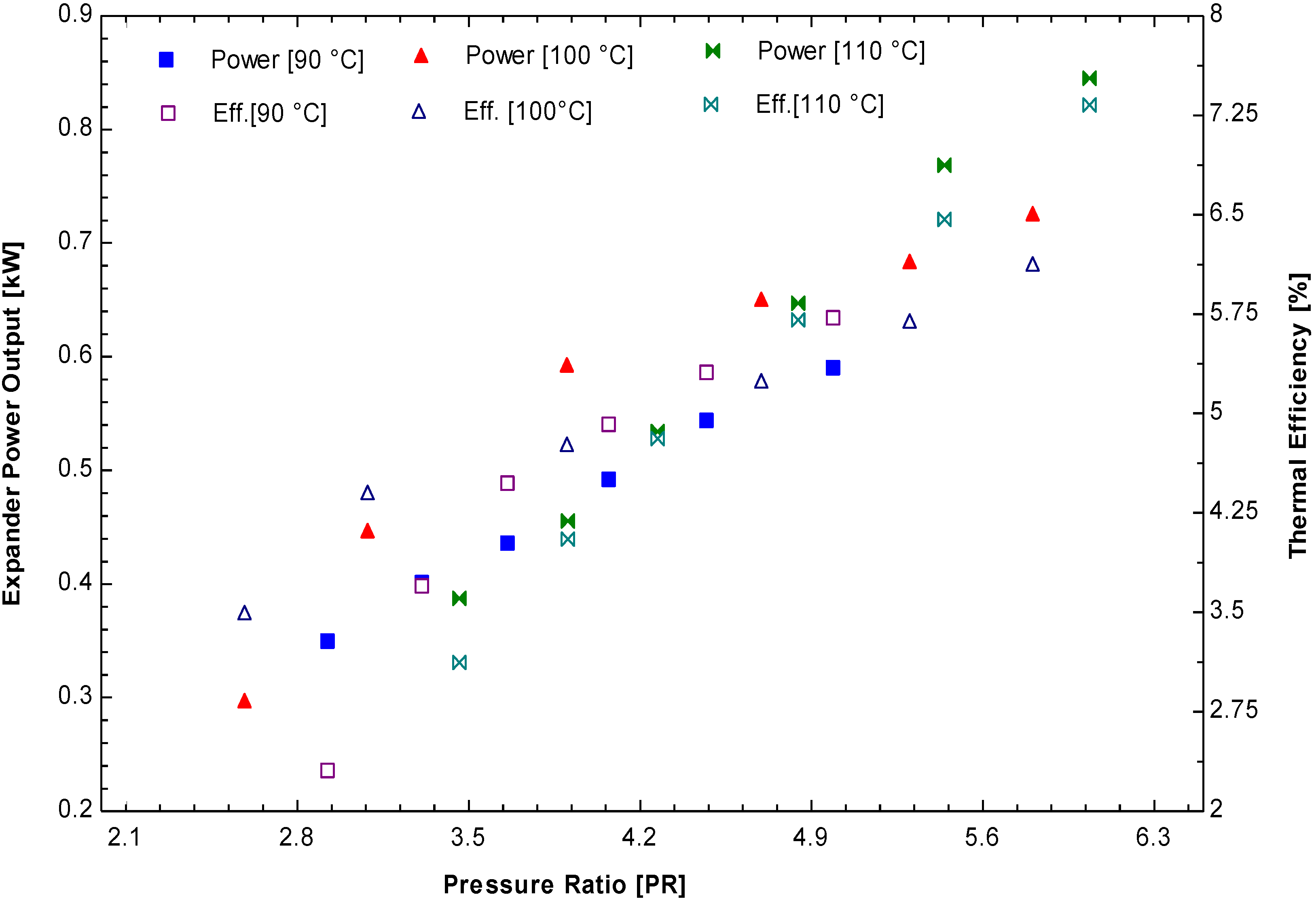
A series of another tests were conducted in the laboratory with different heat source temperature to find the performance, the maximum expander output and thermal efficiency. The low heat source temperature was set at 90 °C, 100 °C and 110 °C and operated with the maximum rotational speed of scroll expander (3600 RPM).
Figure 20 illustrates the variations of expander output power and thermal efficiency with respect to pressure ratio. It was seen that ORC system operating at 90 °C, 100 °C and 110 °C produced maximum power outputs of 0.67 kW, 0.78 kW and 0.87 kW, respectively. The maximum thermal efficiency was found to be 6.5%, 7.1% and 7.5% respectively at the given heat source temperature and pressure ratio. The variation in power output and thermal efficiency is due to low evaporation temperature and pressure. The enthalpy drop across expander decreases and the mass flow rate decreases with decrease in low heat source operating ORC system. If there is no enough sunshine hour (winter season) or partly cloudy climatic conditions, the solar ORC system could be operated in these low heat source temperatures. From the safety and economic efficiency lower pressure and lower mass flow rate ORC system is more suitable.
Figure 20.
Performance parameters: Scroll expander power output and thermal efficiency as a function of pressure ratio at different heat source temperature (3600 RPM).
Figure 20.
Performance parameters: Scroll expander power output and thermal efficiency as a function of pressure ratio at different heat source temperature (3600 RPM).
The success of any technology aimed to install in the rural areas of developing countries depends not only on the thermal efficiency of the system but also on affordability and reliability of the ORC system. The performance of the solar ORC system depends highly on the incident solar isolation, which varies with the geographical position, the time of day and the type of solar collector used. The size of the solar thermal collectors must be well matched in order to obtained highest yield of mechanical and electrical power for the lowest possible cost. The size of the solar collector area can be obtained from the heat input gained during the ORC system. The working fluid mass flow determines the heat energy contained in the ORC system.
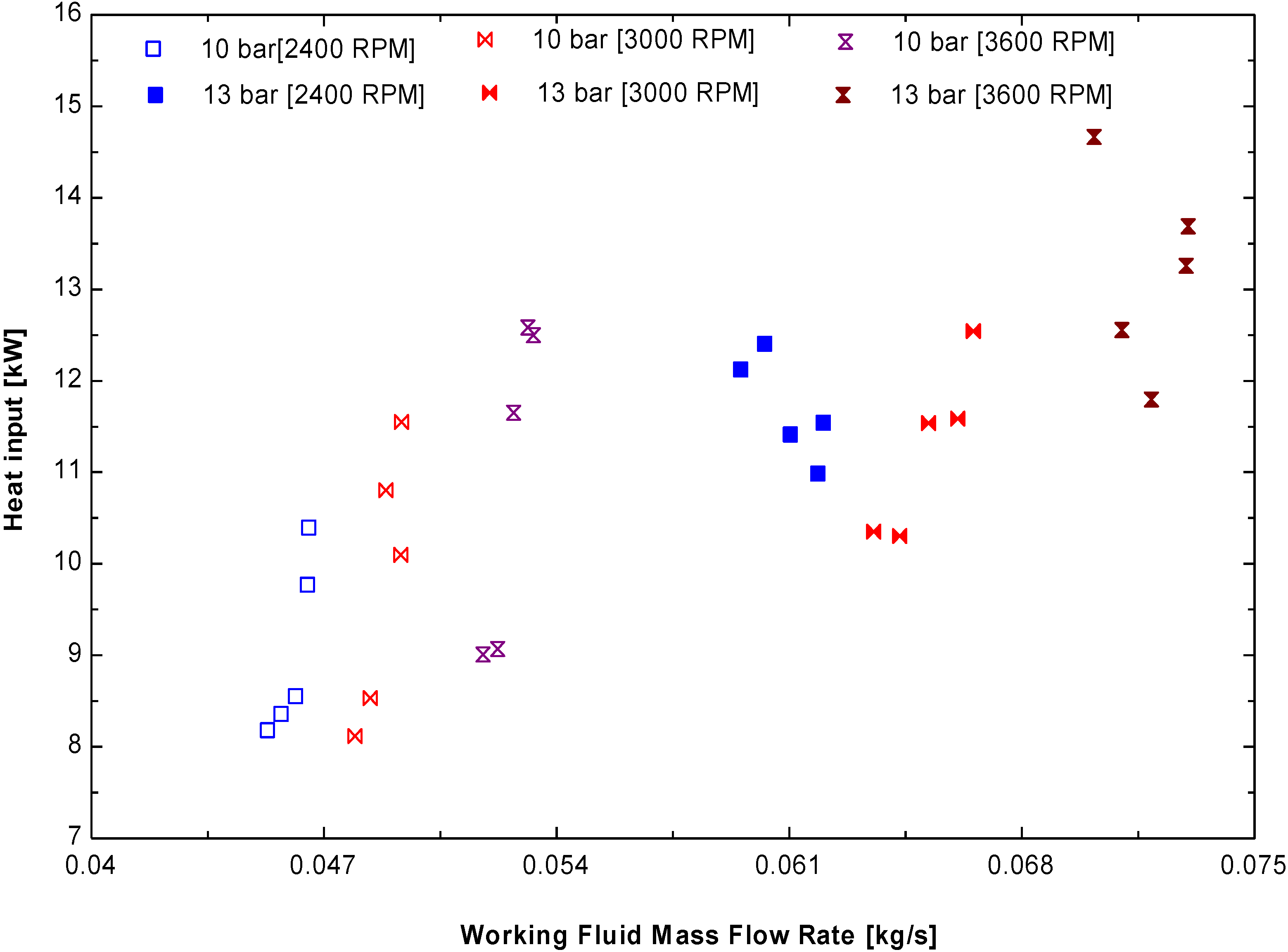
Figure 21 illustrates amount of heat input in the ORC system to produce the mechanical power with respect to mass flow rate of working fluid. For the ORC system operating at 13 bar (3600 RPM), the maximum heat input or heat required to obtain the power output of 1.4 kW need 14.5 kW of heat supply with the working fluid flow rate 0.07 kg/s. On other hand, 10.5 kW heat energy is required to produce 0.98 kW power output with the working flow rate of 0.045 kg/s (10 bar/2400 RPM). It is seen that working fluid mass flow rate depends on the expander’s rotational speed. Higher the operating pressure and rotational speed, the higher is the mass flow rate and heat input. From the literature [
23], it is suggested that the power output of 1 kW requires 25 m
2 of solar collector area.
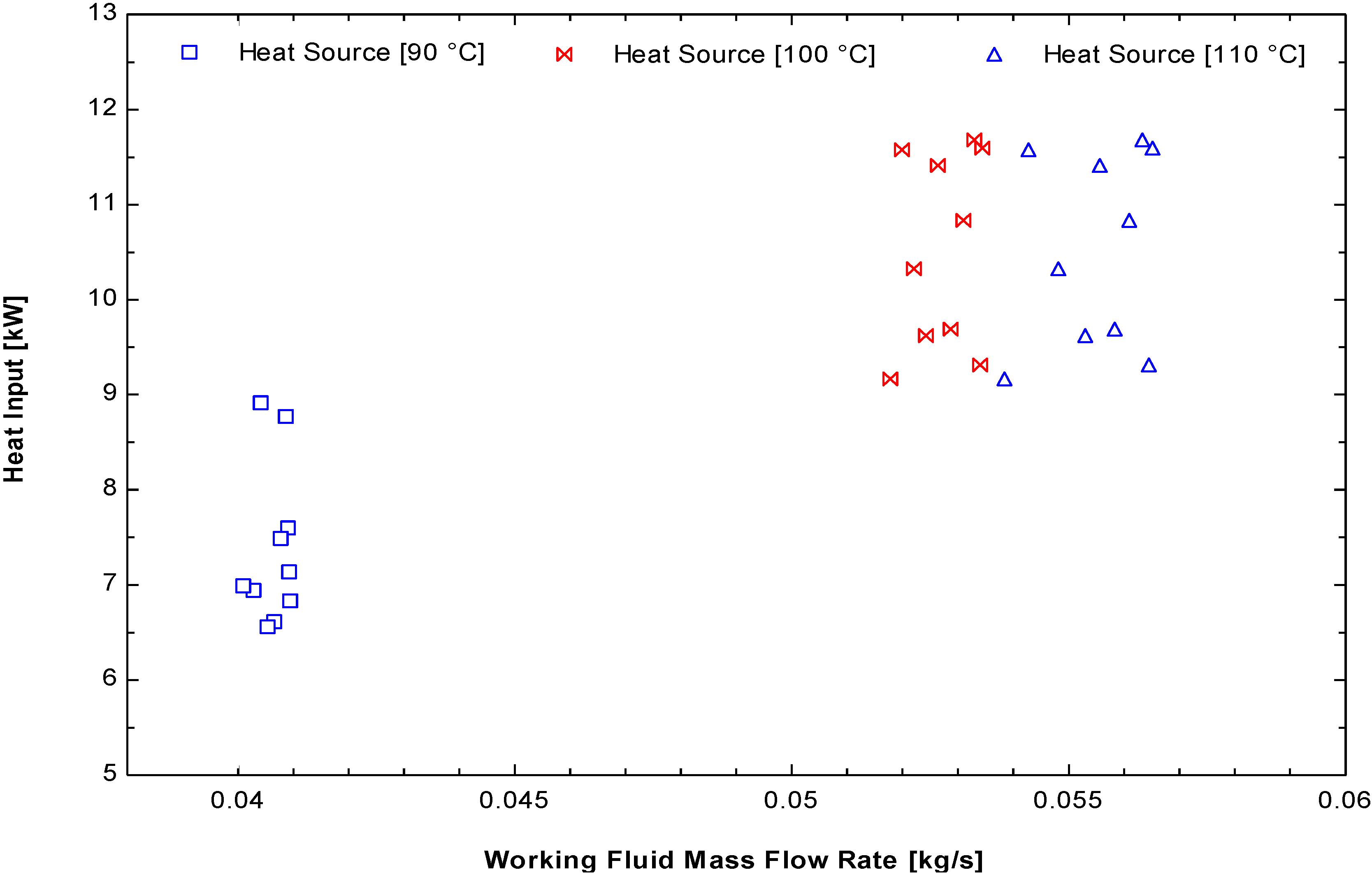
Similarly, from the
Figure 22, the heat input/heat required to produce 0.67 kW of power output requires 8.8 kW of heat energy when the ORC system operating at 90 °C. The working fluid mass flow rate needed is 0.04 kg/s running with the rotational speed of 3600 RPM. In case of 100 °C and 110 °C, the heat inputs are 11.5 kW (0.05 kg/s) and 11.7 kW (0.055 kg/s) respectively.
Different types of solar collectors can be used to obtain the heat energy. From this experimental study it is recommended that heat energy input ranges from 9 to 15 kW to produce the power output of maximum 1.4 kW.
Figure 21.
Performance parameters: Heat input to the ORC system as a function of working fluid mass flow rate at different the expander inlet pressure and rotional speeds.
Figure 21.
Performance parameters: Heat input to the ORC system as a function of working fluid mass flow rate at different the expander inlet pressure and rotional speeds.
Figure 22.
Performance parameters: Heat input to the ORC system as a function of working fluid mass flow rate at different heat source temperature (3600 RPM).
Figure 22.
Performance parameters: Heat input to the ORC system as a function of working fluid mass flow rate at different heat source temperature (3600 RPM).
6. Economics Aspects of ORC Technology
The attractiveness of the ORC in the rural areas of developing countries is strongly correlated with the economic feasibility. This depends on a range of factors, such as investment, operating and maintenance (O&M) costs, interest rates, price of electricity, geographic location, and type of heat source for running an ORC system. The primary cheap renewable resource available in the world is solar energy. Based on the solar collector and the ORC unit, the cost analysis of the system was estimated for rural electrification. Precise information on the current capital cost of the solar ORC that can be suitable for remote areas of developing countries for electricity production is limited. Some papers report that the solar collectors cost may be evaluated as $150–200/m
2 [
25]. The O&M cost for these solar collectors were estimated to be 15% of the investment cost. The capital costs for the solar field and receiver system are a larger percentage of the total costs in ORC plants, whereas the thermal energy storage and power block costs are a smaller percentage. A pilot study conducted by Orosz
et al. [
23] estimated the solar ORC life cycle cost to be $34,000 with a co-generation system (hot water production). The system was installed in rural health clinics of the African country Lesotho, which used a modified Heating, Ventilating & Air Conditioning (HVAC) compressor as an expansion device.
Table 4 lists the investment capital cost (ICC) and O&M cost of the solar ORC system. For the estimation, the amortization factor based on the following relation was implemented:
where
r is the interest rate and set to be 5%, and
LTp is the solar ORC plant lifetime and was set to 20 years.
Table 4.
ICC and O&M costs for the solar ORC components [
25].
Table 4.
ICC and O&M costs for the solar ORC components [25].
| Parameter | ICC, $ | O&M, $ | TCC, $/year | ZIC&OM, $/h |
|---|
| Solar field | 639.5 × (Acol)0.95 | 15% × ICCcol | Af × (ICC + O&M)col | TCCcol/8760 |
| Expander | | | | |
| Evaporator | | | | |
| Condenser | | | | |
| Working fluid Pump | | | | |
The other parameters to be estimated for the cost analysis of the solar ORC system, are the net present cost (NPC), internal rate of return (IRR) and simple payback. The net present cost (NPC) of the solar ORC technology can be calculated to determine the profitability of electricity production along with the internal rate of return (IRR) and payback period. The NPC determines if the solar ORC technology can meet the demands for sustainable development. This is calculated by considering the time series of cash flow, both incoming and outgoing, such as revenue generation, investment on capital, and operation and maintenance costs. The generalized equation for calculating the NPC for energy systems can be expressed as [
23]:
Ot and Mt are the operating and maintenance costs in years, t, respectively. The internal rate of return (IRR) or the economic rate of return (ERR) makes the net present cost of all cash flows (both positive and negative) from a particular investment equal to zero. This can also be defined as the discounted rate at which the present value of all future cash flow is equal to the initial investment, i.e., the rate at which an investment breaks even. Simple payback is the simplest index of economic feasibility that is used widely. Simple payback (SP) is the time period required for an investment to create a positive cash flow.
The investment capital cost (ICC) is calculated by the relationship of purchased equipment cost (PEC, dollars), OH (operating hours per year,
h) and amortization factor which is given by Equation (25) [
26]:
The operation costs
for an individual unit are calculated according to the Equation (26) [
26]:
Finally, the total specific cost rate per kilowatt hour of generated energy (
ctotal) is given by Equation (27) [
26]:
where,
PT and
PP denotes work done by expander and pump, respectively.
To carry out economic analysis, estimations of investment costs of the ORC components are necessary. The prices of components are obtained from the vendor for calculation of the specific cost rate per kilowatt of generated energy. Equations (24)–(27) represent the benchmark of this work. The interest rate amounts to 5%. The total specific cost of the solar ORC system varies at different heat source temperature because of the power output.
Table 5 shows the total specific cost of the solar ORC system when operated with different heat source temperatures. The total specific cost per kWh of power generated depends upon the power output from the ORC system. It is seen that low heat source temperature operating condition cost more than higher operating condition heat source temperature. So it is recommended to operate in the highest heat source temperature. A study conducted by Meinel
et al. [
26] compared total specific cost for different power output scale of ORC and pointed out 500 kW ORC has the total specific cost per kWh to be 0.187 Euro/kWh whereas 5 MW power output ORC has 0.064 Euro/kWh. The small-scale ORC is very expensive in terms of total specific cost per kWh of energy generated. This study investigated that the solar ORC having the power output of 0.63 kW operating at 90 °C heat source temperature costs 0.47 $/kWh. The mass production of the small-scale ORC components could decrease the specific cost per kWh feasible in the rural areas without any subsidies.
Table 5.
Total specific costs per kilowatt hour of generated power [$/kWh].
Table 5.
Total specific costs per kilowatt hour of generated power [$/kWh].
| Heat Source | Total Specific Cost ($/kWh) | Power Output (kW) | Pressure Ratio |
|---|
| 90 °C | 0.47 | 0.63 | 5.6 |
| 100 °C | 0.39 | 0.78 | 5.8 |
| 110 °C | 0.35 | 0.87 | 6 |
| 120 °C | 0.30 | 1.4 | 6.2 |
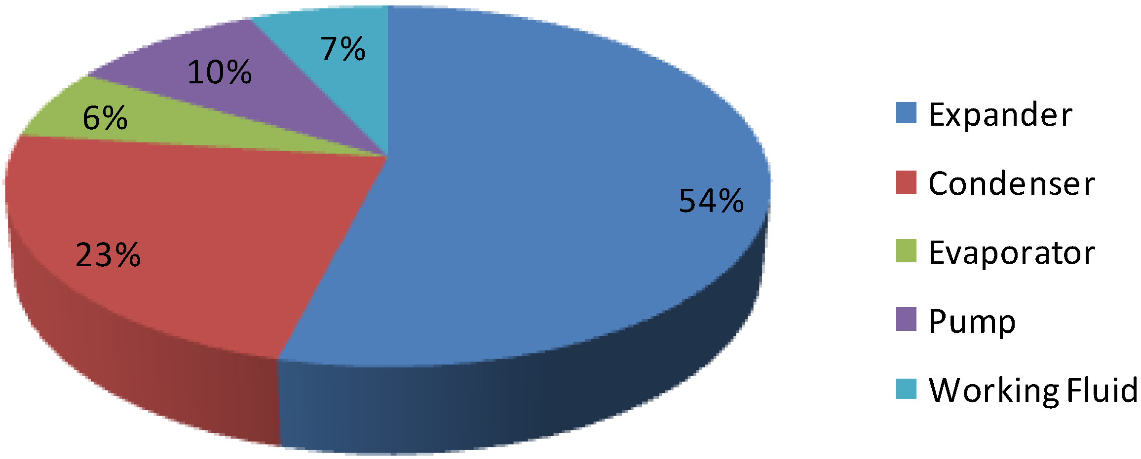
Figure 23 shows the portion of the cost percentage of each component to the total investment cost ($7230) for the small scale ORC compact unit. The evaporator and condenser account for 6% and 23% of the total cost respectively while the scroll expander and working fluid pump represent 54% and 10% of the total cost respectively. The cost of the expander is expensive because the aim is to have the unit oil free and the working fluid leakage free with a low O&M cost. Finally, the R245fa refrigerant accounts for 7% of the total system cost.
Figure 23.
Percentage of the components cost for the ORC unit.
Figure 23.
Percentage of the components cost for the ORC unit.
Note that these costs are associated with the prototype cost of the ORC unit. The mass production of such units would be expected to dramatically reduce the cost by more than half of the current total cost of the ORC unit. Therefore, this type of ORC unit installation can be highly feasible in the isolated areas developing countries for the generation of electricity in the small community using different renewable energy resources for the sustainable development and reduction in an energy poverty level.
ORC technology is widely used for waste heat recovery especially design to extract heat from the industrial waste heat. There are not any ORC units commercial available particularly aimed to implement in remote areas of un-electrified developing countries. The medium and large sized ORC systems are already commercialized. The expander, heat exchangers and working fluids (R245fa) are expensive in the ORC technology. This makes the overall ORC system to be more expensive than other sustainable energy systems. In addition, scroll machine produce low power output and research and development (R&D) on small-scale ORC system is still ongoing. The solar Photovoltaics (PV), small wind turbine, biomass based plant and micro-hydro plant have been used for rural electrification in developing countries. These technologies have been already matured, economically feasible and easy to install. According to the availability of power, the installation cost and O&M cost of these rural electrification systems are different which can be shown in
Table 6 [
27].
Table 6.
Different rural electrification technologies [
27].
Table 6.
Different rural electrification technologies [27].
| Technology | Installed Costs (USD/kW) | O&M Cost (%/year of Installed Costs) |
|---|
| Solar PV system | 1,500–3,000 | 8%–10% |
| Wind power | 3,000–5,000 | 11%–30% |
| Small hydro | 1,300–1,800 | 1%–4% |
Even though the cost of ORC system is high it has following benefits that may make this system more feasible for the rural application:
Easy to install ORC configuration: Since rural areas lack electricity, it is very easy to install the ORC units within short period of time.
Greater equipment longevity: The mechanical stresses on the ORC components are lower due to low pressure and low scroll expander rotational speed (maximum 3600 RPM), the ORC unit can have longer life. Also the parts are easily available in the local market.
Potential use for co-generation/tri-generation applications: The same ORC unit can be used for co-generation applications such as electricity, space heating and cooling and domestic hot water production for rural people living in different climatic conditions.
Environmental cost benefits: If environmental costs are considered, renewable energy sources such as solar ORC system is far better than diesel generators, kerosene base lighting. This helps rural people live healthier and uplift the living standard.
No grid extension cost: Since the ORC system is off-grid system to produce electricity; there is no need of grid- extension. This makes rural electrification more feasible by ORC technology.
7. Subsidies and Financial Mechanisms for ORC System
Several different possibilities can be applied to finance an off-grid rural electrification solar ORC system. The options most commonly applied in developing countries are private financing, financing through the power utility, government financing, and public private partnership. Although the capital cost of a solar ORC system is comparatively higher than other renewable energy technology, a huge subsidy from the government is needed. The subsidies should be regularly provided by the government to ensure financial viability for solar ORC developers/investors and affordability for the customers at the same time. The useful approach for financing a solar ORC system in rural areas is by providing start-up and working capital loans. In the preliminary stages of ORC market development it is important to provide financial support to producers to develop a market and for working capital. On other hand, co-financing should be provided for specific promotional campaigns targeted either geographically or at specific stakeholder groups, such as by banks. In addition, there should be an upper limit on the subsidy amount that is provided, either in the form of the maximum amount per installed kW capacity or as a maximum per household that will be connected. The latter alternative is most appropriate, and can be fixed based on an analysis of the cost structures of implemented ORC systems. Finally, the government’s subsidy support programs should hold to the minimum levels of self-finance of at least 50% for the service providers. The other subsidy is output-based, which can be provided in the form of topping-up kWh payments to the project investors/developers. The solar ORC system can be financed by the government and the public power utility manages and operates the system. The limit of electricity supply for each household is 25–50 kWh. Households pay a monthly electricity fee to the utility following the national electricity tariff set by the government and the difference between the installers cost and households electricity cost is subsidized by the government.
New policies regarding the solar ORC system should be implemented for the effective use of this appropriate technology. Several donor agencies, such as the World Bank, Asian Development Bank (ADB), USAID, International non-governmental organizations (INGOs), National governmental organizations (NGOs) and government bodies, should finance the institutional setup to implement a solar ORC for rural electrification programs. After installing such ORC systems for electricity generation, there are many expected benefits to the community.
Table 7 lists the expected socio-economic impacts of the solar ORC technology if it is implemented successfully in the rural areas of developing countries by increasing the life standard of people and reducing the level of poverty in the country through clean and affordable renewable energy resources.
Table 7.
Expected socio-economic benefits by the solar ORC system.
Table 7.
Expected socio-economic benefits by the solar ORC system.
| Economic | Job creation: The increased number of jobs directly or indirectly created by the solar ORC technology (staff to operate and maintain the ORC facilities, increased economic activity by small home businesses enterprises and productive users). Household income: There is an increase in household income after the provision of electricity. Cut-off in household expenditures: No need to purchase kerosene fuel or other fuels for the lighting of houses. Economic development: By the solar ORC technology it can improve the overall income growth, income per capita, poverty alleviation, etc. thereby uplifting the living standards of the people.
|
| Educational Benefits | Improve quality of teaching and learning process in schools through the provision of electricity-dependent equipment, such as computers, printer, and overhead projector. Increase the study time for children at home during night time by lighting. Improve access to communication devices, such as radio/TV and mobile phones.
|
| Social welfare | Health benefits: Improvements to the community health post, clinics (cooling, lighting); better health due to cleaner air as households reduce the use of polluting fuels for lighting and cooking (indoor-lighting); improve health knowledge through increased access to information on radio/TV. Social benefits: Increased time spent on community activities for the development of community rather than collecting firewood for lighting.
|
| Environmental | |
8. Conclusions
In the first part of this paper, thermodynamic analysis was carried out to determine the performance, functional and operational parameters of small scale ORC systems. The system’s energy and exergy efficiencies were estimated by developing the thermodynamic models. To predict the energy losses in different components of an ORC system, a simulation was carried out under different operating conditions. The maximum exergy destruction in the system was in the evaporator followed by the expander, condenser and pump. In the second part of this paper, the ORC system was tested in the laboratory aiming to install in the remote areas of developing country. The laboratory tests have shown satisfactory performance over a broad range of conditions including different pressure ratios, rotational speeds of the expander and large variations of the heat source temperature.
From the experimental results, the maximum expander power output was 1.4 kW with the expander’s rotating speed of 3600 RPM and inlet pressure of 13 bar. The thermal efficiency of the corresponding condition was 8.55% with a maximum pressure ratio of 5.9. No leakage in working fluid from the scroll expander was observed during the experiment. This is because of the magnetic coupling in the scroll. The maximum isentropic efficiency of the expander was found to be 70%. The indications thus far confirm the robustness of the ORC system, which could be well adapted in the rural areas of developing countries for electricity production. From an economic point of view, the ORC system, which uses solar collectors, could have high capital investment cost due to the cost of the expander and solar collectors. Therefore, rural people cannot afford to buy the ORC system. Instead, different donor agencies, governmental bodies, INGOs and NGOs should help in installing the ORC system that uses solar collectors. The detail economic analysis of the ORC system was not specifically addressed in the present study. The cost of a solar ORC can be decreased by extensive R&D for the small scale ORC system. The medium sized solar ORC has already been commercialized but work remains on a small scale solar ORC system, which should be targeted to power rural villages. In addition, a new policy should be introduced to implement the solar ORC technology in the developing countries. The new policies should include the subsidies from the government to install this appropriate technology and attract investors, manufacturers and developers for sustainable development. At the end of this study, the socio-economic benefits after installing the solar ORC system were discussed.


