1. Introduction
Natural gas hydrates (NGH) are non-stoichiometric crystalline compounds formed by water and small gas molecules under conditions of high pressure and low temperature. NGH deposits have been discovered widely in the world, mainly in marine sediments and permafrost areas. Currently, NGH are regarded as a promising unconventional energy resource, because huge quantities of natural gas are believed to be entrapped in them [
1]. Gas recovery from NGH involves the dissociation of NGH, which can be realized through shifting the
in situ thermodynamic equilibrium conditions. Thermal stimulation, depressurization and thermodynamic inhibitor injection are the three main proposed production methods [
2]. No matter what method is adopted for gas recovery, a certain amount of energy input would be necessary. Otherwise, a significant temperature decline would be inevitable [
3], because the hydrate dissociation process is endothermic. Most likely, the temperature decline will lead to ice formation, slowing or even terminating further hydrate dissociation.
Steam or hot brine injection are the usual approaches of energy input. However, these methods suffer significant energy losses during the heat delivery process. By contrast,
in situ combustion (ISC) is an innovative thermal stimulation concept proposed by Cranganu [
3,
4], which provides the desired heat for hydrate dissociation via a combustion reaction right within the down-hole NGH reservoirs. Schick
et al. [
5,
6] developed a 425-L reservoir simulator and experimentally studied ISC for gas production from methane hydrates, which showed that about 15% of the produced methane should be consumed for all hydrates in the simulator to dissociate. Numerical simulation results indicated that this method can achieve substantial cuts in the needed energy input, with an energy efficiency of 90% [
7].
The ISC methods proposed by Cranganu [
3,
4] and Schick
et al. [
5,
6] were originally aimed at gas production from submarine hydrate reservoirs. They both adopted a closed combustion system, and there was no direct contact between the reservoir and the combustion reaction. The combustion heat is transferred to the reservoir through the wall of the combustor or heat-exchanger. By contrast, ISC would be easier for NGH reservoirs in permafrost regions, where there is much less water with which to deal. Therefore, an open process of combustion in a permafrost NGH reservoir may be possible, which can spare the use of a series of complicated combustion apparatuses. Actually, the open ISC is a well-known method for heavy oil exploitation [
8,
9] and underground coal gasification [
10].
For the permafrost NGH dissociation and recovery using the open ISC method, the flame erupting from the burner nozzle will directly contact the NGH under the down-hole. Therefore, the great concern for this method is the safety issue. It is unclear for us whether the open ISC in the permafrost NGH reservoir will lead to the combustion of whole NGH in sediments and result in the risk of runaway fires. Although we can use the inverse diffusion flame combustion technology to avoid the leakage of oxygen or air into the production well, it is still necessary to investigate the combustion characteristics of hydrates before we can develop successful open ISC technologies for permafrost NGH exploitation. Note that it is challenging to investigate the hydrate combustion characteristics thoroughly, because the hydrate combustion process involves multi-component reactions and multi-phase changes. Moreover, hydrates are hard to keep in normal conditions, due to their special equilibrium properties. Presently, there are only a few publications providing some fundamental knowledge on hydrate combustion. Ueda
et al. made a series of methane hydrate combustion studies, which resembled the classic “Emmons problem” [
11]. Specifically, they investigated the combustion phenomena over methane hydrates in a laminar boundary layer, both numerically and experimentally. Using a one-dimensional thermal model, they first numerically estimated the flame propagation speed over methane hydrates in a laminar boundary layer to be about 1–1.5 mm/s [
12]. Then, their experimental studies showed that the flame propagation speed was in the range of 2–3 mm/s, independent of the free stream velocity [
13]. Later on, they illuminated the mechanism of flame spreading over methane hydrates through combustion experiments with different hydrate surface temperatures [
14,
15]. Two different types of flame propagation phenomena were observed: the so-called “low speed flame spreading” at low surface temperatures, where the methane ejection velocity was slow, and “high speed flame spreading” at high surface temperatures, where the methane ejection velocity was high. In addition, Nakoryakov
et al. [
16] also conducted experiments on methane hydrate combustion, which suggested that the hydrate dissociation rates with combustion exceeded those without combustion by many times.
To investigate the combustion characteristics of natural gas hydrates, methane hydrates should be the first choice, as the majority of naturally occurring NGH are methane hydrates. However, the equilibrium temperature of methane hydrates is about −80 °C under atmospheric pressure, which means that they will decompose intensively at temperatures above 0 °C. To avoid vast dissociation before ignition, the methane hydrates should be kept in a liquid nitrogen condition, where the temperature can be as low as −196 °C. However, such a low temperature would cause the so-called “self-preservation” effect [
17], namely, in combustion experiments, an ice layer would form over the surface of the hydrates, keeping methane from leaving the hydrate structure. To avoid excessive use of liquid nitrogen, as well as the vast dissociation of hydrates before ignition, in this work, we adopted propane hydrates, which have relatively high stability, instead of methane hydrates. Although NGH may exist in various kinds of reservoirs, such as sand, shale and clay, those hydrates in sandy reservoirs are considered the most feasible for economic exploitation [
18]. Presently, much model hydrate reservoir research has been done with quartz sand [
19,
20,
21], and here, we also adopted quartz sand and hydrate mixtures to mimic the permafrost hydrate reservoir.
The main objective was to investigate the combustion characteristics of (1) pure propane hydrates and (2) propane hydrates mixed with different amounts of quartz sands, which are supposed to simulate the porous media in real hydrate reservoirs of different porosities and hydrate saturations. As a matter of fact, the temperatures in permafrost hydrate reservoirs are reported to be above 0 °C (8–12 °C in the world-renowned Messoyakha Field [
22] and 0.79–1.15 °C in Qilian Mountain permafrost [
23]), and for safety considerations, in this work, we conducted the combustion tests at room temperature and atmospheric pressure without the cooling of liquid nitrogen.
2. Experimental Section
2.1. Materials
The analytical pure propane gas with a purity of 99.9% was supplied by Huate Gas Co., Ltd., Foshan, China. The quartz sands were provided by Bandao Quartz Sand Factory, Guangzhou, China. The diameter of the quartz sands is about 0.30–0.45 mm. All aqueous solutions were prepared using de-ionized water, which was prepared by an ultrapure water system (Nanjing Ultrapure Water Technology Co., Ltd., Nanjing, China) with a resistivity of 18.25 MΩ·cm.
2.2. Apparatus and Procedures
The propane hydrate samples were prepared on a self-developed experimental apparatus that has been reported in detail in our previous work [
24]. In brief, the propane hydrate preparing apparatus for the hydrate formation involves a 336-mL cylindrical crystallizer with magnetic stirring, a temperature control system, a gas supply system, a data acquisition system and some temperature and pressure measurement and control units. To synthesize propane hydrate samples, the pressure inside the crystallizer and the supply vessel was set to about 3.8 bar, and the crystallizer was maintained in a 273.65 ± 0.2 K water bath for about three days. The prepared hydrate sample is the slurry of solid hydrates and liquid water, which was cooled by liquid nitrogen before being taken out of the reactor and being dealt with for the combustion experiment. All of the liquid water in the sample was frozen into ice under the lower temperature environment. The frozen solid sample was crushed to a particle size smaller than 5 mm before mixing with quartz sand. The hydrate mass fraction of the sample can be calculated by a gas state equation according to the pressure and temperature data in the reactor and the supply vessel [
24]. The hydrate samples with about a 25% of hydrate mass fraction were prepared for the combustion experiment in this work.
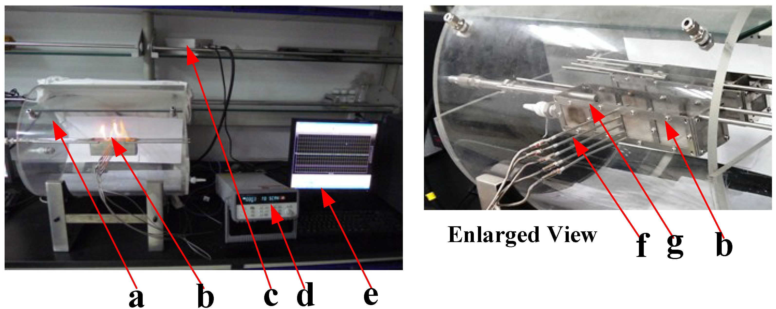
Figure 1 is the photograph of the apparatus used for the hydrate combustion experiment in this work. Specifically, it is composed of a visual combustion chamber (a), a hydrate combustion vessel (b) with an electronic igniter and 5 thermocouples, a switch unit for the electronic igniter (c) and an Agilent Model 34970A data acquisition system (d), which is controlled by a computer (e) through the Agilent data acquisition software application, BenchLink. The combustion chamber (a) is made of a cylindrical refractory glass pipeline with two open sides. The initial temperature in the combustion chamber can be controlled by a temperature controlling water vessel built into the lower part of the combustion chamber. The combustion vessel (b) is installed in the center of the combustion chamber.
Figure 2 displays the schematic of the hydrate combustion vessel (b). The vessel (150 mm in length, 30 mm in width and 50 mm in depth) is made of stainless steel with a 2-mm thickness. There are 5 orifices distributed vertically on one side of the vessel at an interval of 10 mm. Five type-K thermocouples with ±0.1 K accuracy are inserted into the vessel to measure the temperature variation at different depths in the vessel. The five thermocouples, A, B, C, D and E, measure, respectively, the temperatures at the corresponding depths of −5 mm, −15 mm, −25 mm, −35 mm and −45 mm. An electronic igniter is located at the left end of the vessel for ignition. During the combustion test, a digital camera is set to record the combustion phenomena.
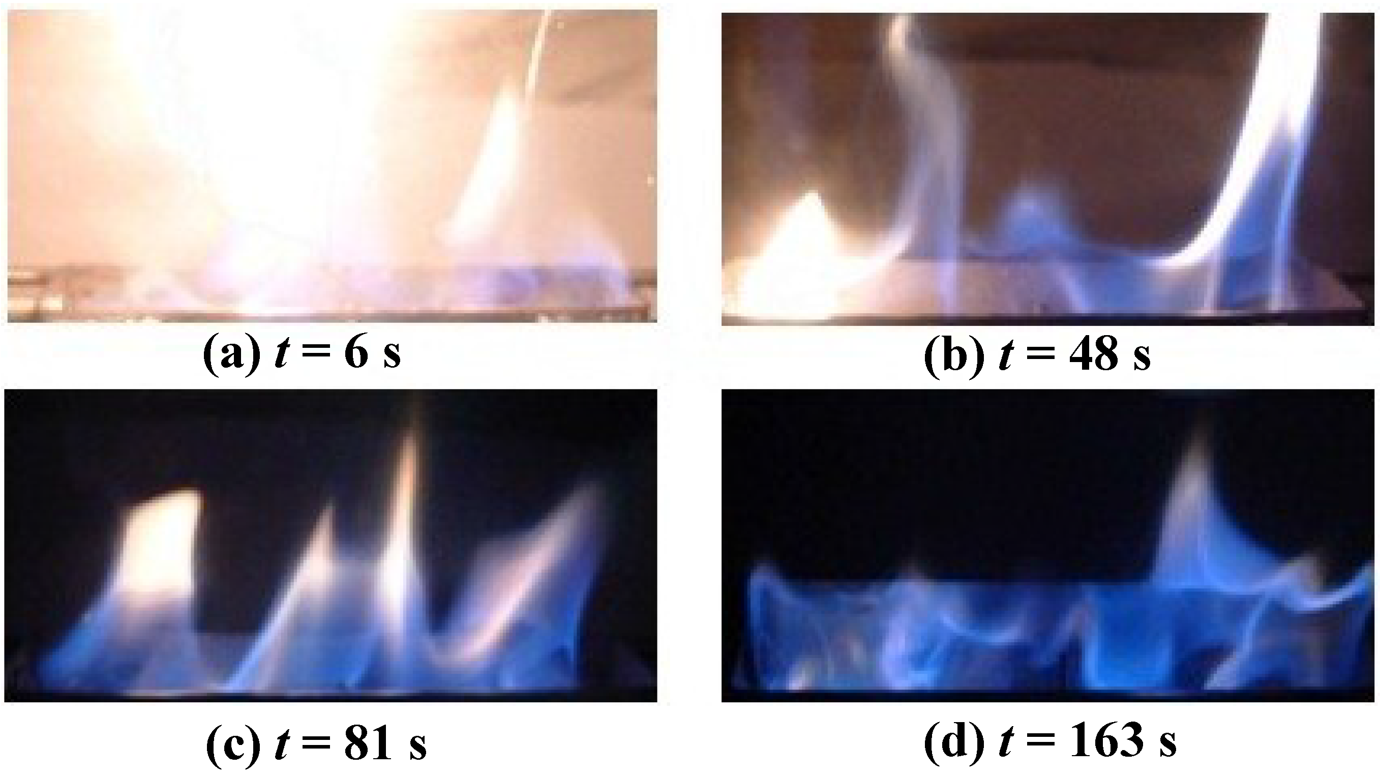
For pure propane hydrate combustion experiments, about 140-g propane hydrate samples were filled into the combustion vessel to the height of the B orifice. The surface was made level. After the vessel was set, the electronic igniter was turned on. After the hydrates were on fire, the electronic lighter was turned off. The temperature variations in the vessel were measured with the 5 type-K thermocouples and were recorded consecutively by the Agilent data acquisition system on the computer at intervals of 1 s. In the meantime, the combustion phenomena were photographed by a digital camera.
Figure 1.
Hydrate combustion test apparatus. a, combustion chamber; b, hydrate combustion vessel; c, switch unit; d, Agilent 34970A data acquisition system; e, computer; f, thermocouples; g, electronic igniter.
Figure 1.
Hydrate combustion test apparatus. a, combustion chamber; b, hydrate combustion vessel; c, switch unit; d, Agilent 34970A data acquisition system; e, computer; f, thermocouples; g, electronic igniter.
Figure 2.
Hydrate combustion vessel.
Figure 2.
Hydrate combustion vessel.
For the combustion experiments of hydrate-sand mixtures, predetermined amounts of propane hydrate samples and quartz sands were mixed carefully in a liquid nitrogen environment before the combustion experiment. The sands were frozen to about −1 °C before they were mixed with the hydrate particles. Then, the mixture was packed into the combustion vessel to the height of the B orifice, which was supposed to simulate the porous media in real hydrate deposits of different porosities and hydrate saturations (SH). The density of the sands is 2.65 g/cm3. The density of the hydrates is estimated as = 0.9 g/cm3.
The overall volume of the mixture is V = 15 × 3 × 3.5 = 157.5 cm3.
The pore volume
Vp is calculated as:
The hydrate saturation
SH is calculated as:
Table 1 lists the mass of the hydrate samples and sands used for different porosities and hydrate saturations. The surface of the mixture was made level. The other procedures were the same as the pure hydrate combustion experiment described above. These experiments involve taking out the hydrates from the pressurized reactor, mixing propane hydrates with quartz sands under a liquid nitrogen environment and ambient pressure, filling the samples into the combustion vessel,
etc. Many factors will result in the hydrate dissolution and sample homogeneity and affect the reproducibility of the experiments, so each case of the combustion experiment was repeated at least three times in this work.
Table 1.
The mass of sand and hydrate samples for different porosities () and hydrate saturations (SH).
Table 1.
The mass of sand and hydrate samples for different porosities () and hydrate saturations (SH).
| Porosity (%) | Hydrate Saturation SH (%) | Mass of Sands ms (g) | Mass of Hydrate Samples mH (g) |
|---|
| 58 | 15 | 175.5 | 48.6 |
| 58 | 11 | 175.5 | 36.5 |
| 58 | 7 | 175.5 | 24.3 |
| 50 | 15 | 210.6 | 42.1 |
| 50 | 11 | 210.6 | 30.8 |
| 50 | 7 | 210.6 | 19.5 |
| 41 | 15 | 245.7 | 34.8 |
| 41 | 11 | 245.7 | 25.5 |
| 41 | 7 | 245.7 | 16.2 |


 ,
, 

