1. Introduction
Ferrosilicon is composed of silicon and iron. In addition, it is one of the essential raw materials for the production of steel and casts, which can improve the chemical and mechanical properties of steel and casts, to improve their quality [
1]. Ferrosilicon is made from coke, silica and steel cuttings by the electric furnace. The ferrosilicon production process includes three steps: raw materials are put into the furnace; coke and silicon iron ore react under electrical heating; and melting ferrosilicon flows out of the furnace. It takes about 24 h every production cycle. The chemical reactions that take place in the process are complex, including oxidation reactions and reduction reactions. There are plenty of fine ash particles generated in the furnace and exhausted out in the flue gas.
Ferrosilicon production is a high-energy consumption and high-pollution process. The production of one ton of ferrosilicon consumes 8000–9000 kW·h and 510–530 kg of coke. The energy consumption accounts for about 40–50 percent of the production cost. A large amount of high temperature waste gas forms in the process. Producing one ton of ferrosilicon alloy, about 50,000 m
3/h of waste gas (450–650 °C) are discharged, and the energy of the high-temperature flue gas takes 40–55 percent of the total energy consumption [
2,
3,
4]. More than half of the energy supplied to the furnace in the form of electricity and raw materials is lost to the environment as heat [
5]. There are more than 1000 ferrosilicon electric furnaces in China, and their waste heat is enormous. Therefore, the waste heat recovery of ferrosilicon electric furnaces is of major importance.
In recent years, several ferrosilicon electric furnaces in China have used HRSGs to recover the heat from the high-temperature flue gas. However, during the operation of the waste heat recovery systems, the HRSGs suffer from serious slagging and fouling, which causes the heat transfer efficiency of the HRSGs to decrease, as well as the evaporation capacity and electricity output to decrease, and some HRSGs even shut down. The slagging and fouling problems have severely restricted the application of HRSGs in ferrosilicon electric furnaces, which is urgent to deal with.
Currently, the study of the ash deposition of boilers has mainly been on utility boilers and industrial boilers [
6,
7,
8,
9,
10,
11,
12,
13,
14,
15]. There is little in the literature about the slagging and fouling of HRSG. In addition, no research has been conducted on the slagging and fouling characteristics of HGSGs for ferrosilicon electric furnaces.
In this paper, we discuss the slagging and fouling mechanism of the HRSG of a ferrosilicon electric furnace in Ningxia, China. The ash samples taken from different parts of the HRSG are analyzed by X-ray fluorescence (XRF), XRD and SEM. The main objective of our work is to estimate the reason for slagging and fouling on HRSGs for ferrosilicon electric furnaces, which will be helpful in reducing the slagging and fouling of HRSGs and crucial to the heat recovery of ferrosilicon electric furnaces.
2. HRSG and Sampling Positions
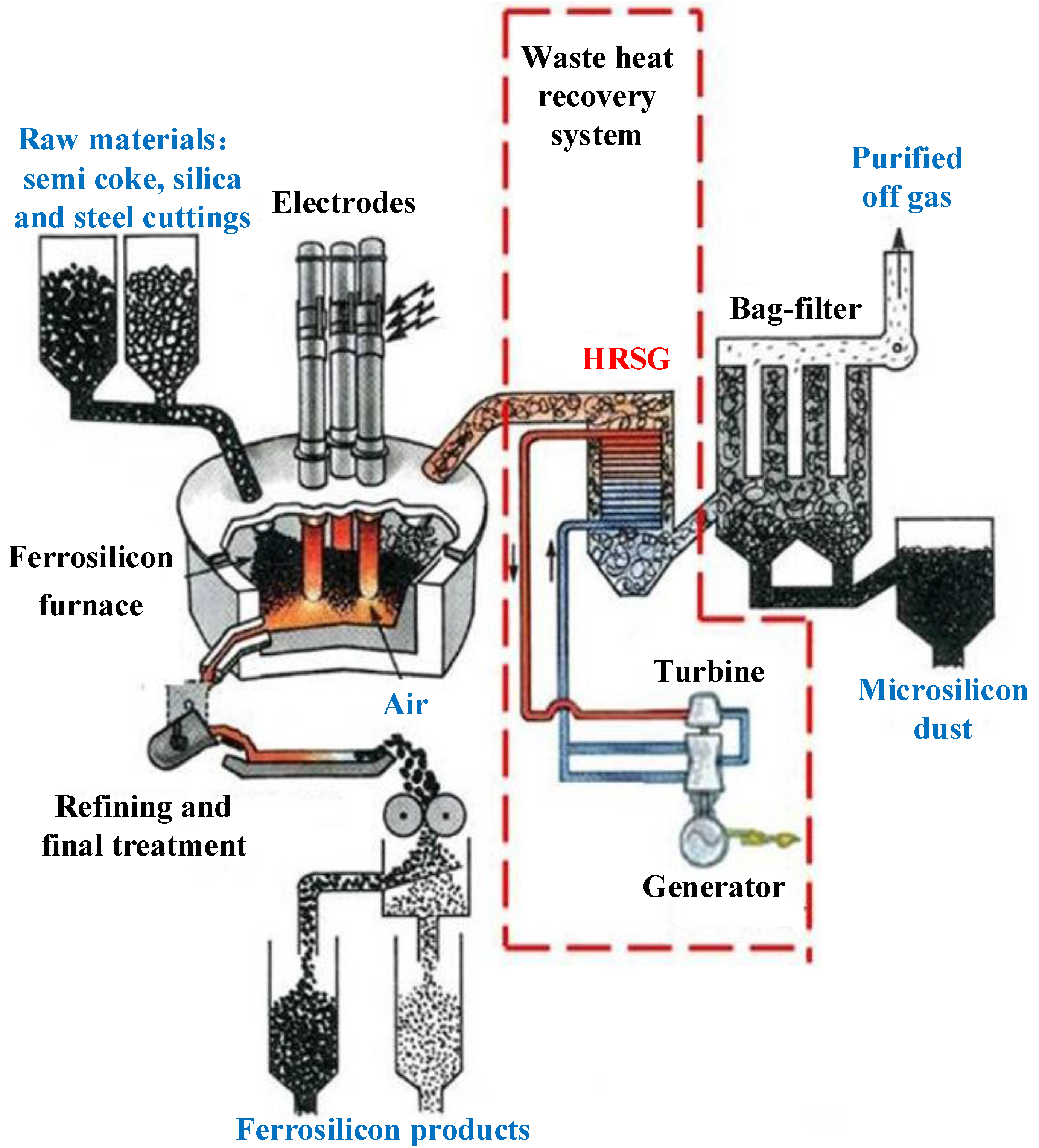
The ash samples are taken from the HRSG of a ferrosilicon electric furnace in Ningxia, China. The rated electric power of the ferrosilicon electric furnace is 18 MW, and the temperature of the reacting area in the furnace is 1700–2000 °C. As shown in
Figure 1, the waste heat recovery system is composed of one forced circulation HRSG, one low-pressure turbine and one generator. The rated power output of the system is 10 MW.
Figure 1.
Diagram of the waste heat recovery system.
Figure 1.
Diagram of the waste heat recovery system.
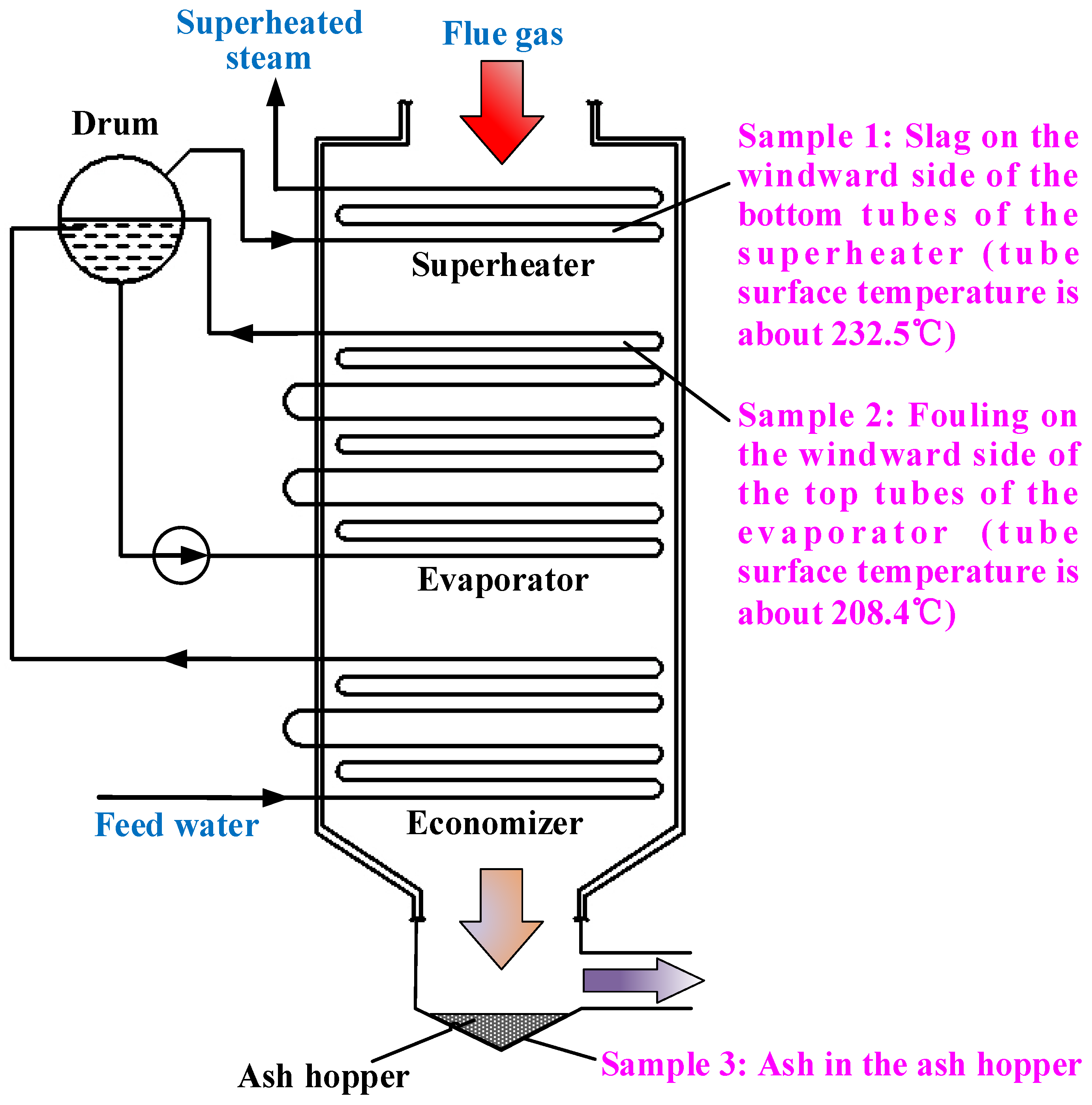
The HRSG (
Figure 2) consists of the one-stage superheater, the three-stage evaporator, the two-stage economizer and the drum. The superheater is composed of smooth tubes, while the evaporator and economizer are made up of pin-finned tubes, which lead to the high heat transfer efficiency of the HRSG. The design parameters of the HRSG are shown in
Table 1. The inlet flue gas temperature of the HRSG changes periodically with the production cycle of the ferrosilicon electric furnace. Its minimum is about 450 °C, and its maximum is about 700 °C. During 90% of the production cycle, the inlet flue gas temperature is maintained at about 600 °C. The inlet flue gas components are as shown in
Table 2. In addition,
Table 3,
Table 4 and
Table 5 show the components of the raw materials. An ash blowing technology, consisting of combustion gas and pulsing, is used to clean the deposited ash every two hours.
Figure 2.
Diagram of the HRSG and sampling positions.
Figure 2.
Diagram of the HRSG and sampling positions.
Table 1.
Operating parameters of the HRSG.
Table 1.
Operating parameters of the HRSG.
| Parameters | Unit | Value |
|---|
| Inlet flow of flue gas | Nm3·h−1 | 50,000 |
| Rated temperature of inlet flue gas | °C | 600 |
| Temperature range of inlet flue gas | °C | 450–700 |
| Pressure of superheated steam | MPa | 1.27 |
| Temperature of superheated steam | °C | 320 |
| Rated evaporating capacity | t/h | 10 |
| Rated temperature of outlet flue gas | °C | 170 |
Table 2.
Components of the inlet flue gas (on a volume basis).
Table 2.
Components of the inlet flue gas (on a volume basis).
| Components | Unit | Value |
|---|
| CO2 | % | 3 |
| N2 | % | 77.5 |
| O2 | % | 18.3 |
| H2O | % | ≤1.2 |
| Ash | g·m−3 | ≤10 |
Table 3.
Components of the silica (wt%).
Table 3.
Components of the silica (wt%).
| Components | SiO2 | Fe2O3 | Al2O3 | CaO | MgO | Others |
|---|
| Value | 98.42 | 0.67 | 0.42 | 0.24 | 0.13 | 0.12 |
Table 4.
Proximate analysis of the semi-coke (wt%, as received basis).
Table 4.
Proximate analysis of the semi-coke (wt%, as received basis).
| Moisture | Ash | Volatile Matter | Fixed Carbon |
|---|
| 7.4 | 3.5 | 2.8 | 86.3 |
Table 5.
Ash composition of the semi-coke (wt%).
Table 5.
Ash composition of the semi-coke (wt%).
| SiO2 | Al2O3 | Fe2O3 | CaO | MgO | Na2O | K2O |
|---|
| 54.22 | 17.38 | 16.26 | 2.13 | 3.89 | 1.64 | 4.48 |
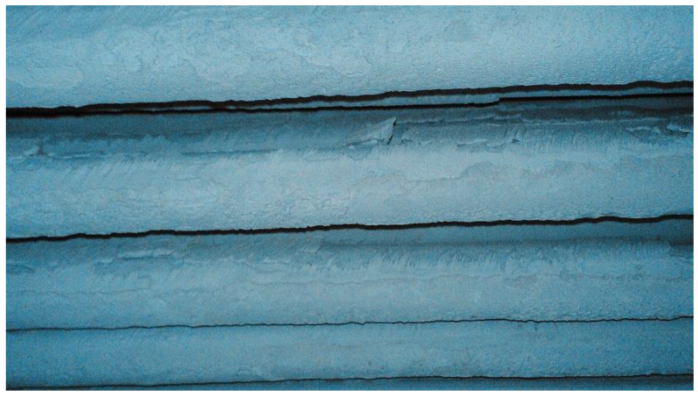
In the operation of the HRSG, the superheater suffers from serious slagging (
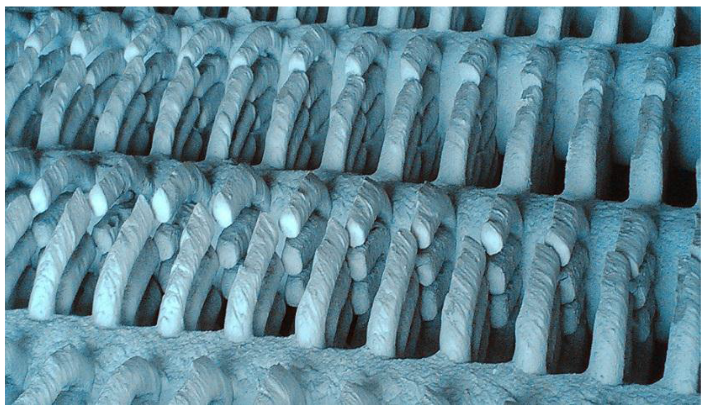
Figure 3), which causes the superheated steam temperature to be less than the design value. Meanwhile, the evaporator suffers from serious fouling (
Figure 4), resulting in the decline of the evaporation capacity. During the daily operation, the evaporation capacity is about 8 t/h (designed value: 10 t/h), and the superheated steam temperature is maintained at about 280 °C (designed value 320 °C). When evaporation capacity is maintained at 8 t/h and the superheated steam temperature is maintained at 280 °C, the actual temperatures of each heating surfaces are measured, as shown in
Table 6.
Figure 3.
Slagging on the superheater.
Figure 3.
Slagging on the superheater.
Figure 4.
Fouling on the evaporator.
Figure 4.
Fouling on the evaporator.
Table 6.
Inlet flue gas temperatures of the heating surfaces.
Table 6.
Inlet flue gas temperatures of the heating surfaces.
| Heating surface | Superheater | Evaporator | Economizer |
|---|
| Temperature/°C | 590–605 | 545–555 | 215–225 |
When the HRSG is shut down, the samples are taken from the slagging, fouling and ash deposition parts, as shown in
Figure 2. In addition, the tube surface temperatures of sampling Positon 1 and Positon 2 are calculated based on the temperature of the working medium inside, which is also illustrated in
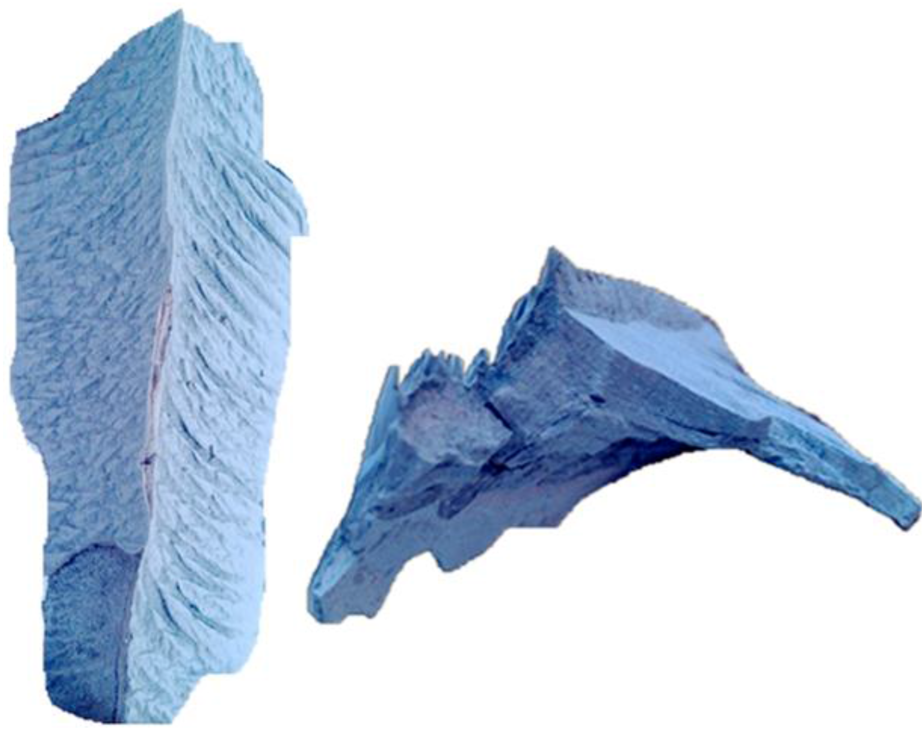
Figure 2. Because of the manhole and shutdown time limitations, only three positions were available for taking samples. Sample 1 is the slag on the windward side of the bottom tubes of the superheater. Sample 2 is the fouling on the windward side of the upper tubes of the evaporator. Sample 3 is the ash deposited in the ash hopper, with the standard ash in the flue gas for comparison. The slag body of Sample 1 is gray brown and uniform without obvious layers, as shown in
Figure 5. Sample 2 is composed of fragile, small ash blocks, and Sample 3 is fine ash.
3. Experimental Section
The samples were ground, and the main crystalline compounds in the samples were identified by XRD. XRF was used for elemental determination. Comparing the XRF with XRD results, the compound contents of each sample are inferred. In order to obtain the physical morphology characteristic of each sample, SEM was applied to observe the sample microstructures. By synthetically analyzing the above consequences, the reasons for slagging and fouling can be proposed.
4. Results and Discussion
4.1. Sample Analysis Results
4.1.1. XRF Analysis Results
Table 7 shows the XRF analysis results of the three samples. Mg, K, Fe, Si and O are the main elements in every sample, while there is less Na, Ca, S, Al, Zn and Mn. Compared with that in Sample 3, the contents of Na, Ca and Fe are obviously higher in Sample 2 and Sample 3. Sample 1 contains more S than Sample 2 and Sample 3. Moreover, the content of Fe in Sample 2 is the highest.
Table 7.
X-ray fluorescence (XRF) analysis results of the ash samples.
Table 7.
X-ray fluorescence (XRF) analysis results of the ash samples.
| Sample | Na | Ca | Mg | K | S | Fe | Si | O | Al | Zn | Mn |
|---|
| 1 | 2.11 | 2.35 | 2.61 | 4.75 | 5.4 | 7.89 | 24.2 | 48.9 | 0.948 | 0.171 | 0.314 |
| 2 | 2.23 | 2.45 | 2.62 | 4.71 | 2.45 | 12.4 | 26.7 | 44.7 | 0.607 | 0.248 | 0.354 |
| 3 | 1.53 | 1.05 | 3.18 | 4.55 | 1.79 | 6.31 | 31.6 | 48.1 | 0.398 | 0.274 | 0.209 |
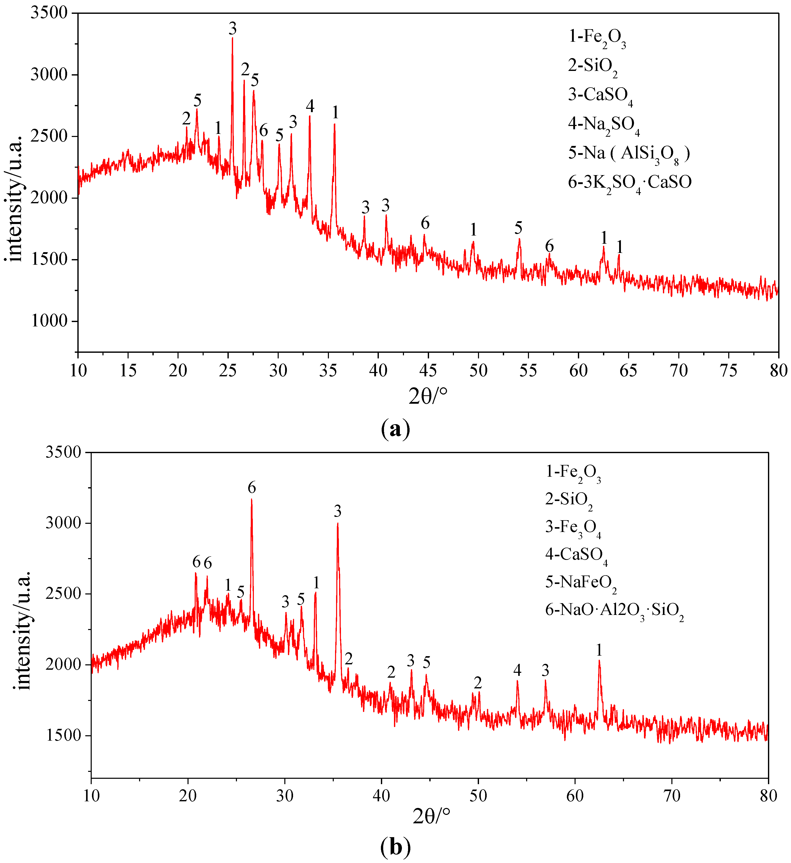
4.1.2. XRD Analysis Results
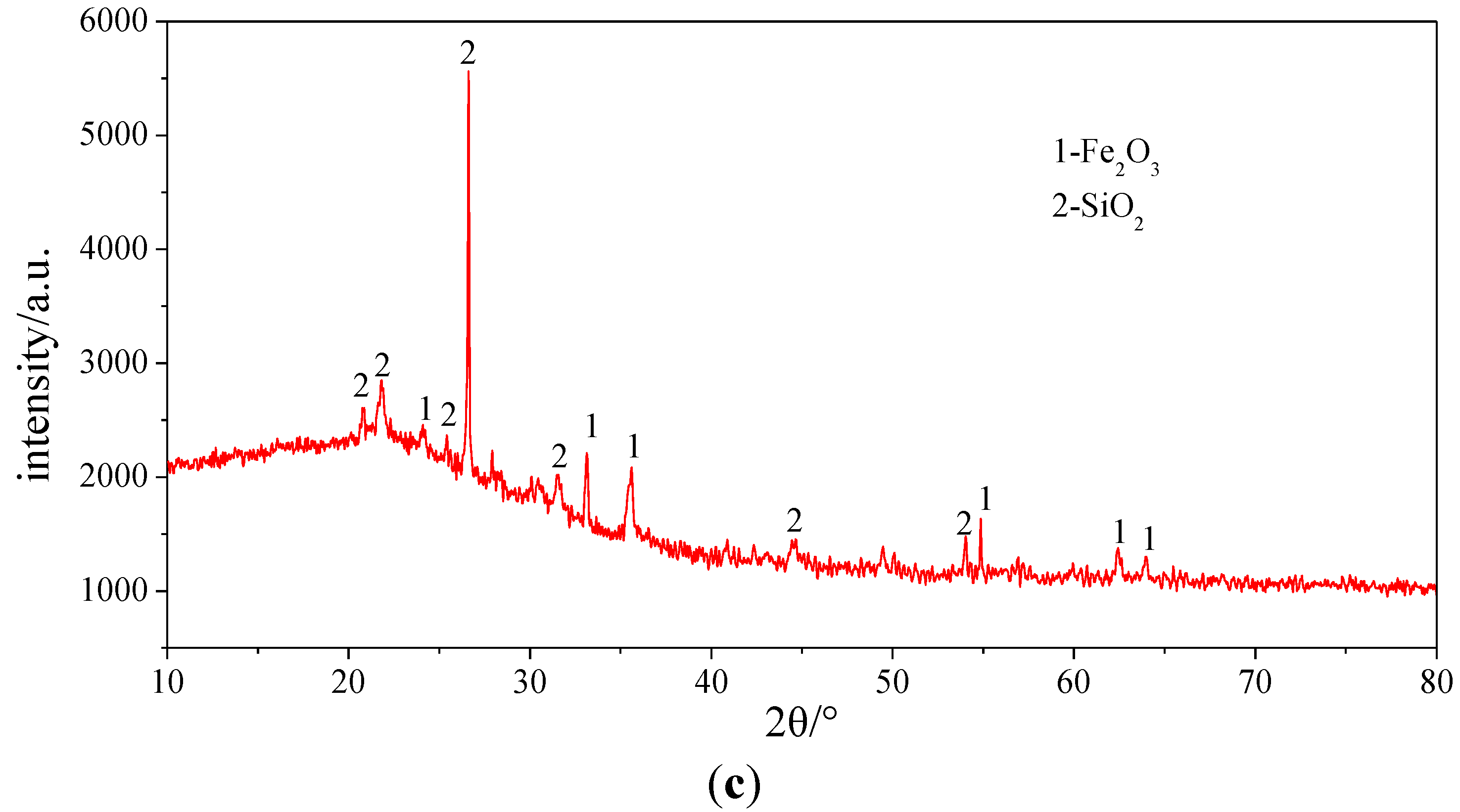
To determine the compounds in which the elements exist, the three samples were analyzed by XRD. The results of XRD illustrated in
Figure 6 and
Table 8 indicate that Si and Fe mainly exist in SiO
2 and Fe
2O
3 in each sample. Because of Fe
2O
3, Sample 1 appears grey brown. CaSO
4, Na
2SO
4, Na (AlSi
3O
8) and 3K
2SO
4·CaSO
4 are also the main compounds in Sample 1. In addition, there are other compounds, CaSO
4, NaFeO
2, NaO·Al
2O
3·SiO
2, existing in Sample 2.
Figure 6.
XRD analysis pictures of the ash samples. (a) Sample 1; (b) Sample 2; (c) Sample 3.
Figure 6.
XRD analysis pictures of the ash samples. (a) Sample 1; (b) Sample 2; (c) Sample 3.
Table 8.
XRD analysis results of the ash samples.
Table 8.
XRD analysis results of the ash samples.
| Sample | Main components |
|---|
| 1 | Fe2O3, SiO2, CaSO4, Na2SO4, Na (AlSi3O8), 3K2SO4·CaSO4 |
| 2 | Fe2O3, SiO2, Fe3O4, CaSO4, NaFeO2, NaO·Al2O3·SiO2 |
| 3 | Fe2O3, SiO2 |
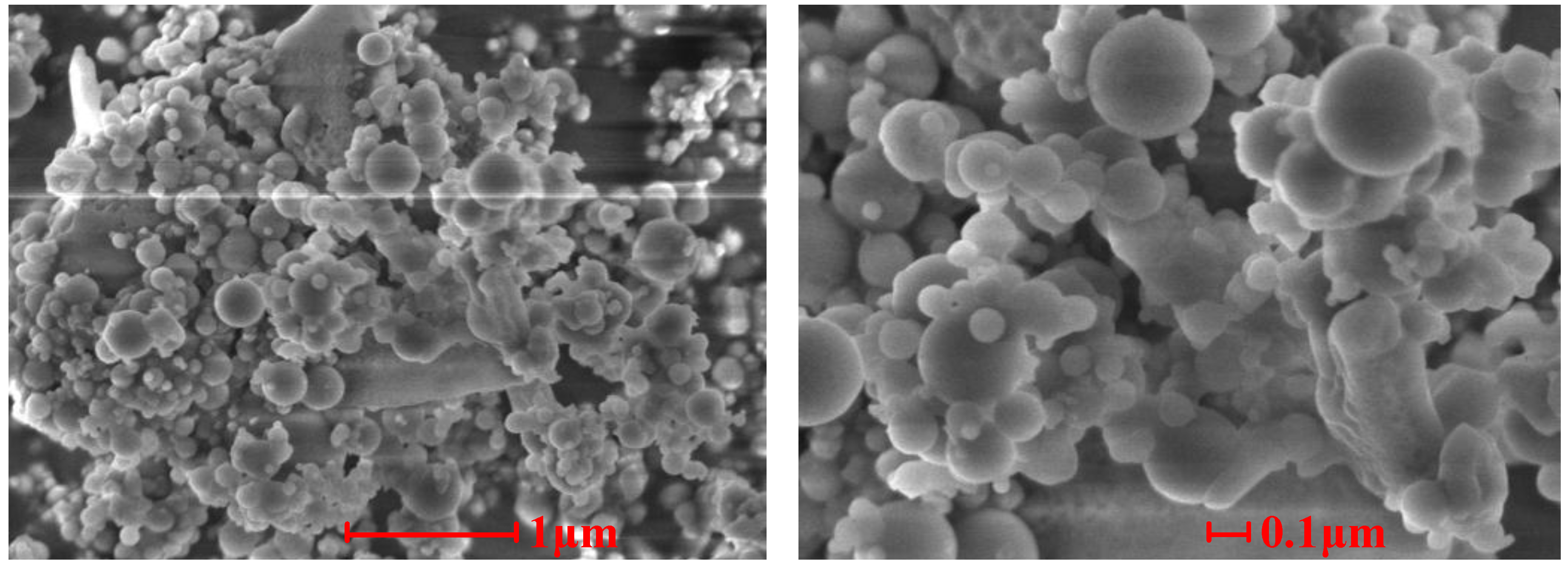
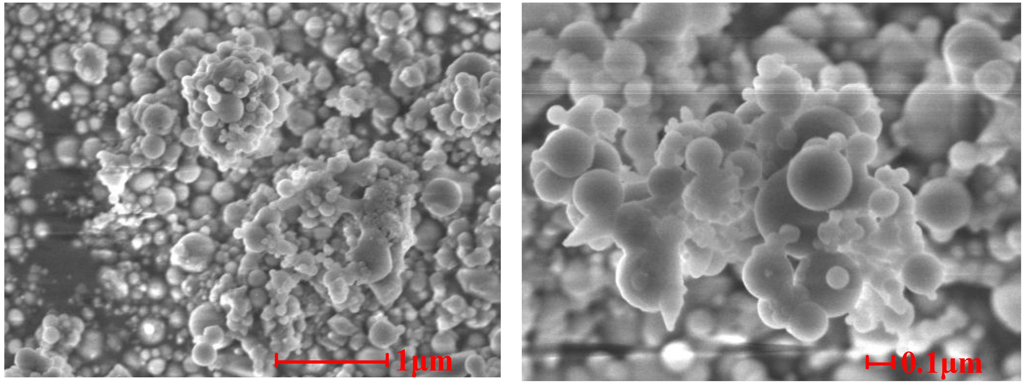
4.1.3. SEM Analysis Results
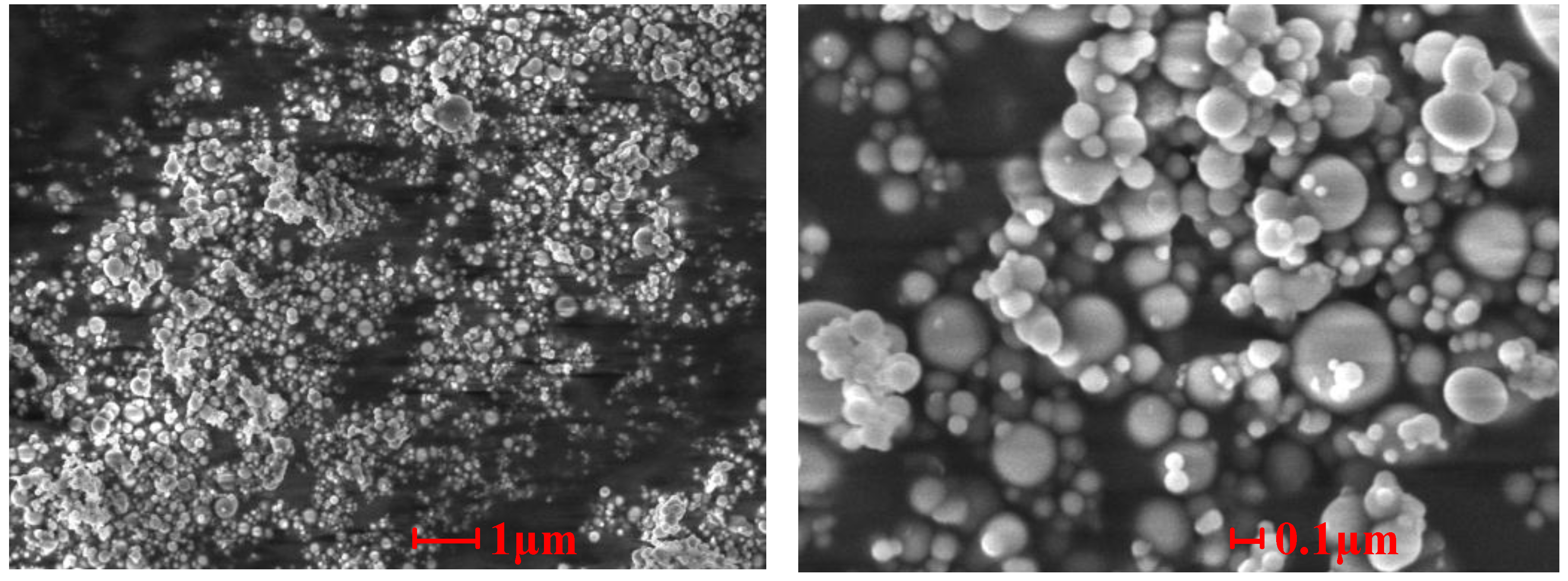
Figure 7,
Figure 8 and
Figure 9 show the SEM photographs of the microstructures of the three samples. It is obvious that the ash particles in the flue gas are almost all spherical and less than 1 μm, and many them are less than 0.1 μm. These superfine particles are easily deposited on other particles or tube walls. There are obvious signs that melting particles merged and absorbed other ash particles in Sample 1 and Sample 2, which indicates that melting low melting point compounds play an important role in the slagging and fouling process. From
Figure 7 and
Figure 8, we can note that ash particles bonded to each other by sintering of low melting compounds and superfine particles.
Figure 9 shows that the superfine particles adhere to other particles. Since there were no melting compounds, no strong connections between ash particles were built.
Figure 7.
SEM photographs of the cross-sectional structures of Sample 1.
Figure 7.
SEM photographs of the cross-sectional structures of Sample 1.
Figure 8.
SEM photographs of the cross-sectional structures of Sample 2.
Figure 8.
SEM photographs of the cross-sectional structures of Sample 2.
Figure 9.
SEM photographs of the cross-sectional structures of Sample 3.
Figure 9.
SEM photographs of the cross-sectional structures of Sample 3.
4.2. Slagging and Fouling Mechanism Analysis
4.2.1. Slagging Mechanism
A lot of research has shown that the slagging and fouling on heating surfaces during coal combustion are usually related to alkali metal elements Na and K [
16,
17,
18,
19,
20,
21,
22]. As shown in
Table 4, the ash in the flue gas exhausted from the ferrosilicon electric furnace has high Na and K contents, which leads to easy slagging and fouling.
Table 4 and
Table 5 show that Na, Ca and S are enriched in Sample 1, existing in sulfates (CaSO
4 and Na
2SO
4) and composite salts (Na (AlSi
3O
8) and 3K
2SO
4·CaSO
4), which means that the slagging on the superheater is probably related to the chemical reactions and migration of Na, Ca and S.
In the high temperature area of the furnace, most alkali metal does not attach to the walls, but vaporizes or sublimates and suspends in the high temperature area or flies out with the flue gas [
23]. Under high temperature conditions, alkali metal gasifies in the form of low melting point salts, such as KCl, NaCl and Na
2SO
4 [
16,
24,
25]. In addition, there are low melting point composite slats forming in the furnace [
14,
26,
27].
Table 4 and
Table 5 shows that there are low melting point salt Na
2SO
4 and composite salts Na (AlSi
3O
8) and 3K
2SO
4·CaSO
4 existing in Sample 1, which results in the slagging on the superheater. When the high temperature flue gas comes to the middle temperature area (the superheater), a lot of these low melting point salt and composite salts begin to condense and form aerosol particles. In addition, these aerosol particles are usually super fine, less than 1 μm and even 0.1 μm [
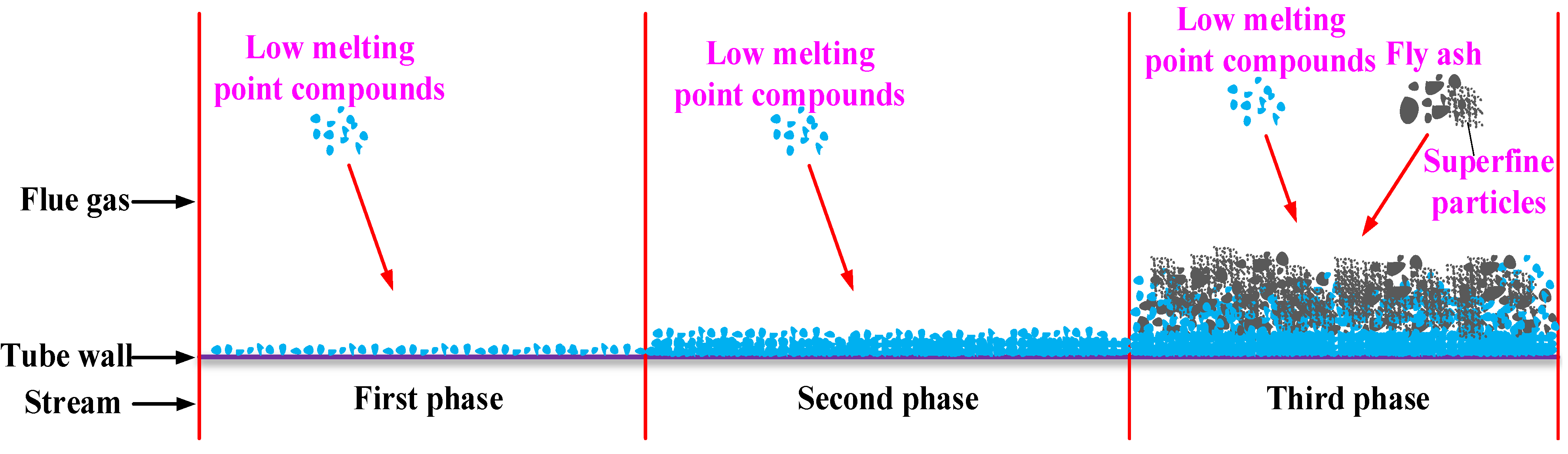
25]. Therefore, these aerosol particles are easily deposited on the tube walls with the effects of electrostatic force and thermophoretic force, solidifying and forming the initial slag layer. As more and more low melting point compounds are deposited on the tube walls, the thermal resistance of the slag increases, the slag surface temperature increases and the low melting point compounds solidify more slowly, but the viscosity of the slag surface increases. Meanwhile, the surface area and surface roughness of the slag increase several times over. Then, more and more ash particles in the flue gas are absorbed on the slag surface to form a thicker slag. In addition,
Section 4.1.3. shows that the ash particles in the flue gas are superfine and easily deposited, which accelerates the slagging progress. The slagging process is illustrated in
Figure 10.
Figure 10.
Diagram of the slagging process.
Figure 10.
Diagram of the slagging process.
4.2.2. Fouling Mechanism
From
Table 4 and
Table 5, we can see that Na and Fe are enriched in Sample 2, existing as s Fe
2O
3, Fe
3O
4, NaFeO
2 and NaO·Al
2O
3·SiO
2, which means that the fouling on the evaporator is closely related to Na and Fe.
When the flue gas reaches the evaporator, low melting point composite salt NaO·Al
2O
3·SiO
2 adheres to tube walls in aerosol form. With the deposition of NaO·Al
2O
3·SiO
2, more and more ash particles are absorbed to form the fouling. Many superfine fly ash particles also promote the fouling formation. Besides, there are numerous, large, iron-rich slag particles in the flue gas [
18]. Since there is less space between pin-finned tubes, the large iron-rich slag particles are easily deposited on the tube walls and fin surfaces, which also facilitates the fouling process. The fouling process is similar to the slagging process. However, because of different formation temperatures, the low melting point compounds deposited in the fouling differ from that in the slag, and the slag body is tough, while the fouling body is frangible.
5. Conclusions
(1) Low melting point salt Na2SO4 and composite salts Na (AlSi3O8) and 3K2SO4·CaSO4 adhere to the superheater tube walls in aerosol form and solidify to form the initial slag layer. With the continuous deposition of the low melting point compounds, the thermal resistance of the slag increases, the slag surface temperature increases and the low melting point compounds solidify more slowly, but the viscosity of the slag surface increases. Meanwhile, the surface area and surface roughness of the slag increase several times over. Then, more and more ash particles in the flue gas are absorbed on the slag surface to form a thicker slag.
(2) Low melting point composite salt NaO·Al2O3·SiO2 adheres to the evaporator tube walls in aerosol form. With the deposition of NaO·Al2O3·SiO2, more and more ash particles are absorbed to form the fouling. Since there is less space between pin-finned tubes, the big, iron-rich slag particles are easily deposited on the tube walls and fin surfaces, which is advantageous to the fouling process. In addition, the fouling process is similar to the slagging process. Because of different forming temperatures, the low melting point compounds deposited in the fouling are different from that in the slag.
(3) There are a lot of superfine ash particles in the flue gas that easily adhere to other particles or tube walls, which facilitates the slagging and fouling process.
Acknowledgments
This research was supported by the Specialized Research Fund for the Doctoral Program of Higher Education (No. 20130201110045) and the Fundamental Research Funds for the Central Universities.
Author Contributions
Yungang Wang, Qinxin Zhao and Heng Chen conceived of and designed the experiments. Heng Chen, Yungang Wang, Zhongya Chen and Haidong Ma performed the experiments. All authors analyzed the data. All authors discussed the results and co-wrote and commented on the manuscript.
Conflicts of Interest
The authors declare no conflict of interest.
References
- Wang, Q.; Liu, W. Ferroalloy Production Technology and Equipment; Metallurgical Industry Press: Beijing, China, 2009; pp. 3–6. [Google Scholar]
- Schneider, W.R.; Eyrich, J.F. Operation of a 75 Kva, 75 percent ferrosilicon furnace with heat recovery equipment. Electr. Furn. Conf. Proc. 1974, 32, 180–182. [Google Scholar]
- Jorgensen, K.; Kildahl, J. Energy recovery from electric ferrosilicon furnace waste gas. In Proceedings of the 41st Electric Furnace Conference, Detroit, MI, USA, 6–9 December 1984; Iron and Steel Society of the American Institute of Mining: Detroit, MI, USA, 1984; pp. 19–23. [Google Scholar]
- Malcho, M.; Jandacka, J.; Komandera, I. Heat regain from electric arc furnaces with ferrosilicon production. In Proceedings of the VIII Internationales Symposium-Warmeaustausch und Erneuerbare Energiequellen, Leba Szczecin, Poland, 18–20 September 2000; Wydawnictwo Uczelniane Politechniki Szczecinskiej: Leba Szczecin, Poland, 2000; pp. 255–260. [Google Scholar]
- Saevarsdottir, G.; Hjartarson, H.; Palsson, H. Waste heat utilization from a submerged arc furnace producing ferrosilicon. In Proceedings of the 12th International Ferroalloys Congress, INFACON 2010, Helsinki, Finland, 6–9 June 2010; Outotec Oyj: Helsinki, Finland, 2010; pp. 739–748. [Google Scholar]
- Ram, L.C.; Tripathi, P.; Mishra, S.P. Mossbauer spectroscopic studies on the transformations of iron-bearing minerals during combustion of coals-correlation with fouling and slagging. Fuel Process Technol. 1995, 42, 47–60. [Google Scholar] [CrossRef]
- Erickson, T.A.; Allan, S.E.; Mccollor, D.P.; Hurley, J.P.; Srinivasachar, S.; Kang, S.G.; Baker, J.E.; Morgan, M.E.; Johnson, S.A.; Borio, R. Modeling of fouling and slagging in coal-fired utility boilers. Fuel Process Technol. 1995, 44, 155–171. [Google Scholar] [CrossRef]
- Huang, L.Y.; Norman, J.S.; Pourkashanian, M.; Williams, A. Prediction of ash deposition on superheater tubes from pulverized coal combustion. Fuel 1996, 75, 271–279. [Google Scholar] [CrossRef]
- Wang, H.F.; Harb, J.N. Modeling of ash deposition in large-scale combustion facilities burning pulverized coal. Progress Energy Combust. 1997, 23, 267–282. [Google Scholar] [CrossRef]
- Vuthaluru, H.B.; Wall, T.F. Ash formation and deposition from a Victorian brown coal-modelling and prevention. Fuel Process Technol. 1998, 53, 215–233. [Google Scholar] [CrossRef]
- Vuthaluru, H.B. Remediation of ash problems in pulverised coal-fired boilers. Fuel 1999, 78, 1789–1803. [Google Scholar] [CrossRef]
- Naganuma, H.; Ikeda, N.; Kawai, T.; Takuwa, T.; Ito, T.; Igarashi, Y.; Yoshiie, R.; Naruse, I. Control of ash deposition in pulverized coal fired boiler. Proc. Combust. Instit. 2009, 32, 2709–2716. [Google Scholar] [CrossRef]
- Fang, Q.Y.; Wang, H.J.; Wei, Y.; Lei, L.; Duan, X.L.; Zhou, H.C. Numerical simulations of the slagging characteristics in a down-fired, pulverized-coal boiler furnace. Fuel Process Technol. 2010, 91, 88–96. [Google Scholar] [CrossRef]
- Akiyama, K.; Pak, H.; Takubo, Y.; Tada, T.; Ueki, Y.; Yoshiie, R.; Naruse, I. Ash deposition behavior of upgraded brown coal in pulverized coal combustion boiler. Fuel Process Technol. 2011, 92, 1355–1361. [Google Scholar] [CrossRef]
- Ma, Z.H.; Iman, F.; Lu, P.S.; Sears, R.; Kong, L.B.; Rokanuzzaman, A.S.; McCollor, D.P.; Benson, S.A. A comprehensive slagging and fouling prediction tool for coal-fired boilers and its validation/application. Fuel Process Technol. 2007, 88, 1035–1043. [Google Scholar] [CrossRef]
- Takuwa, T.; Mkilaha, I.; Naruse, I. Mechanisms of fine particulates formation with alkali metal compounds during coal combustion. Fuel 2006, 85, 671–678. [Google Scholar] [CrossRef]
- Shimogori, M.; Mine, T.; Ohyatsu, N.; Takarayama, N.; Matsumura, Y. Effects of fine ash particles and alkali metals on ash deposition characteristics at the initial stage of ash deposition determined in 1.5 MWth pilot plant tests. Fuel 2012, 97, 233–240. [Google Scholar] [CrossRef]
- Yang, S. Research on Coal-Fired Utility Boiler Slagging prediction Models and Diagnostic Software; China Water Power Press: Beijing, China, 2011; pp. 4–11. [Google Scholar]
- Osborn, G.A. Review of sulfur and chlorine retention in coal-fired boiler deposits. Fuel 1992, 71, 131–142. [Google Scholar] [CrossRef]
- Oleschko, H.; Schimrosczyk, A.; Lippert, H.; Muller, M. Influence of coal composition on the release of Na-, K-, Cl-, and S-species during the combustion of brown coal. Fuel 2007, 86, 2275–2282. [Google Scholar] [CrossRef]
- Oleschko, H.; Muller, M. Influence of coal composition and operating conditions on the release of alkali species during combustion of hard coal. Energy Fuel 2007, 21, 3240–3248. [Google Scholar] [CrossRef]
- Li, R.D.; Kai, X.P.; Yang, T.H.; Sun, Y.; He, Y.G.; Shen, S.Q. Release and transformation of alkali metals during co-combustion of coal and sulfur-rich wheat straw. Energy Convers. Manag. 2014, 83, 197–202. [Google Scholar] [CrossRef]
- Rao, S.; Cao, X.; Lan, Z.; Zhao, X.; Zhou, J.; Cen, K. Characteristic of mineral species distribution in furnace and its influence on the slagging during coal combustion. J. Fuel Chem. Technol. 2004, 32, 395. [Google Scholar]
- Li, Y.; Xiao, J.; Zhang, M. Modeling and prediction of migration mechanism of alkali metals during coal-fired process. Ranliao Huaxue Xuebao/J. Fuel Chem. Technol. 2005, 33, 556–560. [Google Scholar]
- Xu, M. Formation and Emission of Coal Combustion Inhalable Particles; Science Press: Beijing, China, 2009; pp. 22–38. [Google Scholar]
- Yoshiie, R.; Tsuzuki, T.; Ueki, Y.; Nunome, Y.; Naruse, I.; Sato, N.; Ito, T.; Matsuzawa, Y.; Suda, T. Effects of coal types on ash fragmentation and coalescence behaviors in pulverized coal combustion. Proc. Combust. Instit. 2013, 34, 2895–2902. [Google Scholar] [CrossRef]
- Bilirgen, H. Slagging in PC boilers and developing mitigation strategies. Fuel 2014, 115, 618–624. [Google Scholar] [CrossRef]
© 2015 by the authors; licensee MDPI, Basel, Switzerland. This article is an open access article distributed under the terms and conditions of the Creative Commons Attribution license (http://creativecommons.org/licenses/by/4.0/).


