1. Introduction
A microgrid is a small power system that includes distributed generation (DG), an energy storage system, and a controllable load [
1,
2]. In general, a microgrid operates optimally with the microgrid central controller (MGCC), which can control DG and the controllable load in addition to monitoring the microgrid system [
3]. Typically, the microgrid can be operated in islanded mode or grid-connected mode [
4]. In the islanded mode, the MGCC has to ensure power balance and control of voltage and frequency in the microgrid, but in the grid-connected mode, the MGCC can operate more economically because the utility grid is responsible for solving problems such as voltage control and frequency oscillation in the microgrid.
Intelligent agents can determine their performance autonomously by recognizing the surrounding environment and communicating with other agents. On the basis of these features, the microgrid can be operated using a number of agents. Recently, a microgrid operation technique through multi-agent system (MAS) has been studied [
5,
6]. Similar to the central control method of a traditional power system, a top-level agent or energy management system ensures the optimal operation of a microgrid through hierarchical information exchange between agents with specific purposes [
6]. Each agent has its own operation algorithm. Therefore, this is a distributed control method involving cooperation or competition between agents for optimal operation [
7].
In recent power systems, demand response (DR) is also important. DR technology can solve problems such as peak reduction, expansion of facilities, and transmission congestion. The DR changes the electricity price, and therefore consumers can adjust their load to reduce the price. The DR program can be classified as a price-based DR program and an incentive-based DR program. Price-based DR has time-of-use, day-ahead pricing (DAP), critical peak pricing, and real-time pricing (RTP). Incentive-based DR has emergency demand response (EDR), direct load control, and capacity market program (CMP) [
8].
In the centralized control method of the microgrid, the MGCC aggregates all the information for optimal operation using a genetic algorithm (GA) [
9], particle swarm optimization, and dynamic programming (DP) [
10]. In this method, the DG and the battery energy storage system (BESS) output are determined in accordance with the MGCC optimization results. This optimization method is suitable for the best operation, but the calculation time is long, and all data are required at the MGCC. However, in the distributed control method, the MGCC sends the electricity price and state of the grid to agents for distribution control. Its role is minimal and confined to sending signals pertaining to the stability of the microgrid. In the other method of microgrid control, the system includes an agent platform for the agent’s trade [
7].
This study examined the operation strategy of a microgrid that consists of a BESS and an intelligent load using MAS. The MGCC can monitor the output through each agent and send data for each distributed independent operation. This study examined the economic operation algorithm using a fuzzy system for the BESS that receives the minimum information from the MGCC. The operation algorithm of an intelligent load agent, with the load assumed to be an industrial load, was also studied for maximum benefit by calculating the hourly production cost [
11]. The two agents schedule using DAP and perform a real-time operation when EDR occurs. As the microgrid is connected to the grid, the microgrid maintains stability at the point of common coupling (PCC). Therefore, the MGCC in this study ensures individual agent operation. However, if the microgrid becomes unstable, the MGCC intervenes in the agent’s operation to restore microgrid stability.
This paper is organized as follows:
Section 2 examines each agent operation algorithm and the MGCC operation algorithm. In
Section 3, the proposed algorithm is analyzed with different simulation scenarios through hardware-in-the-loop system (HILS) test by constructing the agents and the MGCC.
Section 4 describes the hardware test performed with a new distribution simulator for comparison with the HILS test results in
Section 3. Finally,
Section 5 presents the conclusions of the study.
2. Operation Algorithms of Individual Agents
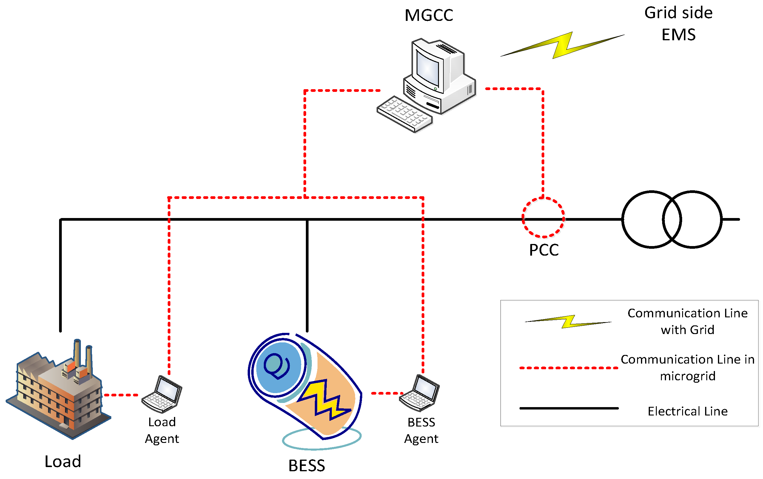
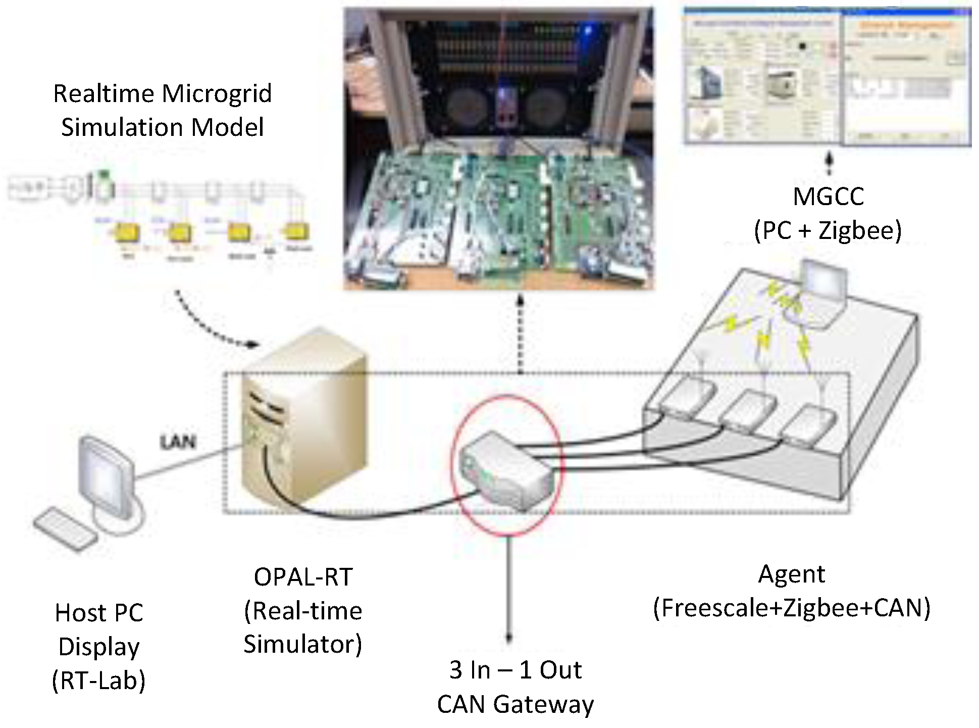
In this study, a test microgrid is constructed with a BESS, an intelligent load, and an MGCC that can communicate with two agents as shown in
Figure 1. Each agent executes operation algorithms independently without affecting each other. Because the test microgrid is assumed to be for a commercial purpose, the owner of all components may be different. Thus, for independence and stability of the system, the MGCC receives data from the grid-side energy management system (EMS) and sends data and signals to two agents, each of which has two operation algorithms: a day-ahead scheduling algorithm and a real-time algorithm in accordance with the EDR signal. The price data for scheduling is used in the DAP, which is one of the DR programs. On any day, the DAP program notifies the price of 24 h electricity for the next day. Similarly, EDR is included in the DR program.
The BESS agent has the objective of maximizing the economic benefit from the energy arbitrage [
12]. In addition, because it maintains a certain state-of-charge (SOC) range, the agent can contribute to power system stability by discharging when an emergency situation occurs. The intelligent load agent that assumes an industrial load performs production scheduling through DAP to minimize the electricity price. The agent can compare the sales benefit and incentive for participation in EDR and determine whether to participate in EDR. The detailed algorithm is described as follows.
Figure 1.
Configuration of microgrid in this paper.
Figure 1.
Configuration of microgrid in this paper.
2.1. Algorithm for BESS Agent
The BESS is used for frequency regulation, system reserve, demand-side management capacity, and augmentation of renewable energy resources [
13]. In this study, the scheduling algorithm of the BESS is designed using a fuzzy expert system that can obtain an appropriate margin during the day and a real-time operation algorithm is responsible for handling emergency situations. The fuzzy expert system utilizes fuzzy logic to represent ambiguous scenarios instead of Boolean logic [
14].
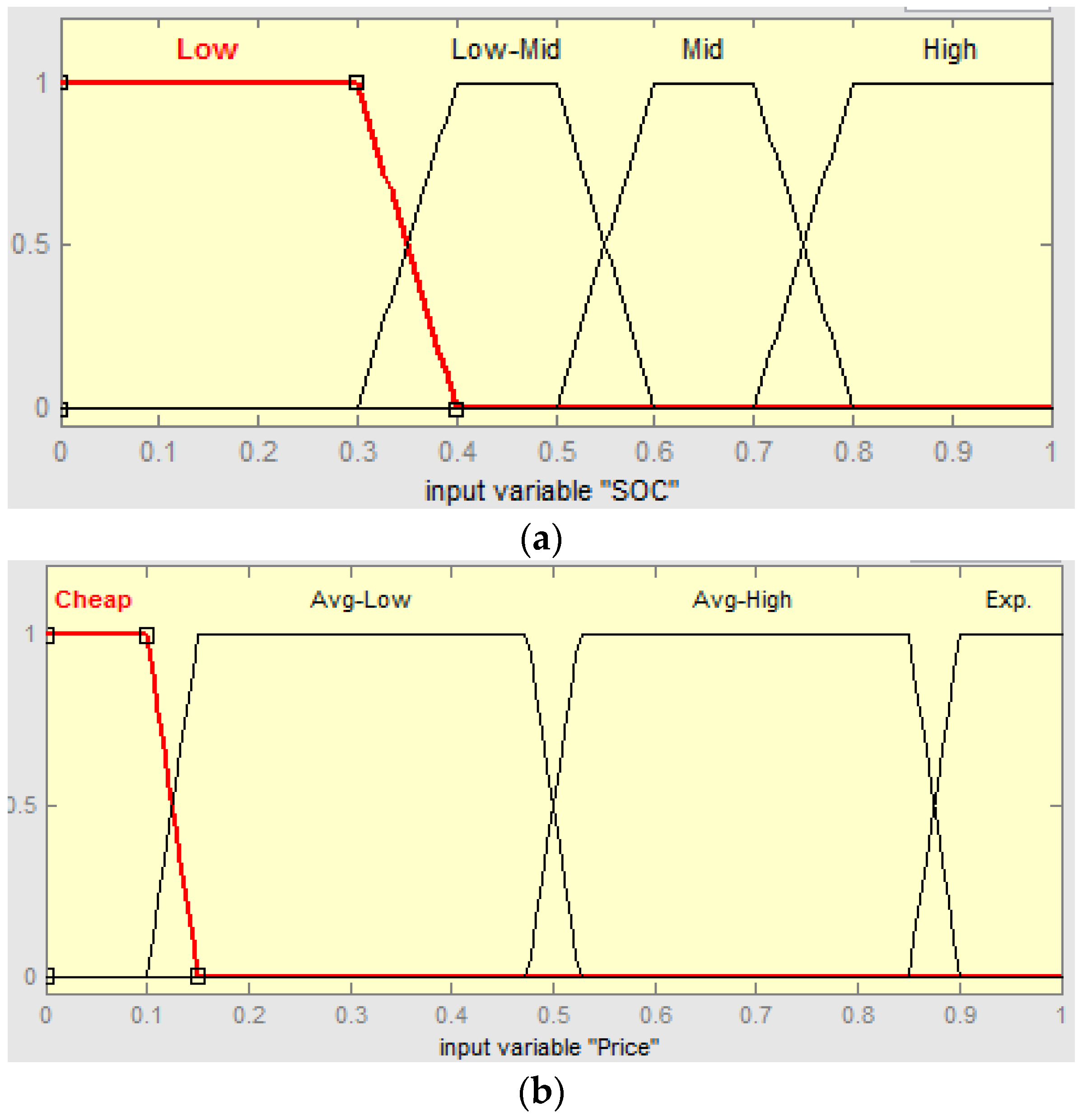
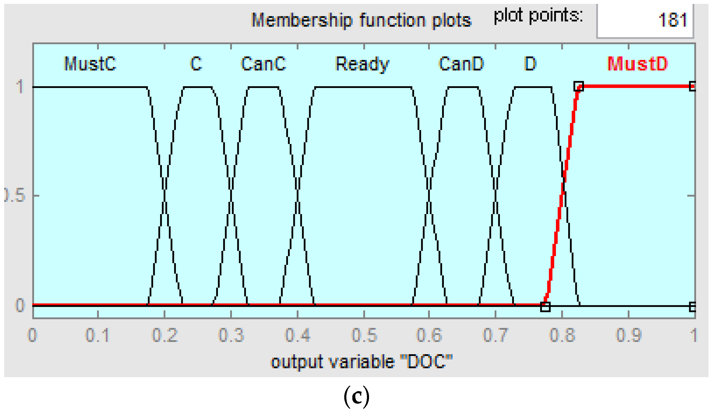
Figure 2.
Fuzzy membership function (a) state of charge (SOC), (b) electricity price, (c) decision of charge.
Figure 2.
Fuzzy membership function (a) state of charge (SOC), (b) electricity price, (c) decision of charge.
In this study, the scheduling algorithm was designed to determine if it is charging or discharging using the fuzzy system as the input membership functions of the BESS SOC and hourly DAP.
Figure 2 shows a membership function of the fuzzy system applied in this study. In the step-by-step descriptions, the BESS’s SOC and the electricity price are determined by a preset fuzzy input membership function. The output membership function is determined by the SOC and the electricity price membership function through the fuzzy rule.
Table 1 represents the fuzzy rule in this algorithm. All cases were evaluated and combined. Finally, the charge/discharge value was determined by the scalar value whose aggregated output membership function is defuzzification by the centroid method.
Table 1.
Fuzzy rule.
| SOC/Price | Cheap | Avg-Low | Avg-High | Expensive |
|---|
| Low | Must Charge | Charge | Can Charge | Ready |
| Low-Mid | Charge | Can Charge | Ready | Can Discharge |
| Mid | Can Charge | Ready | Can Discharge | Discharge |
| High | Ready | Can Discharge | Discharge | Must Discharge |
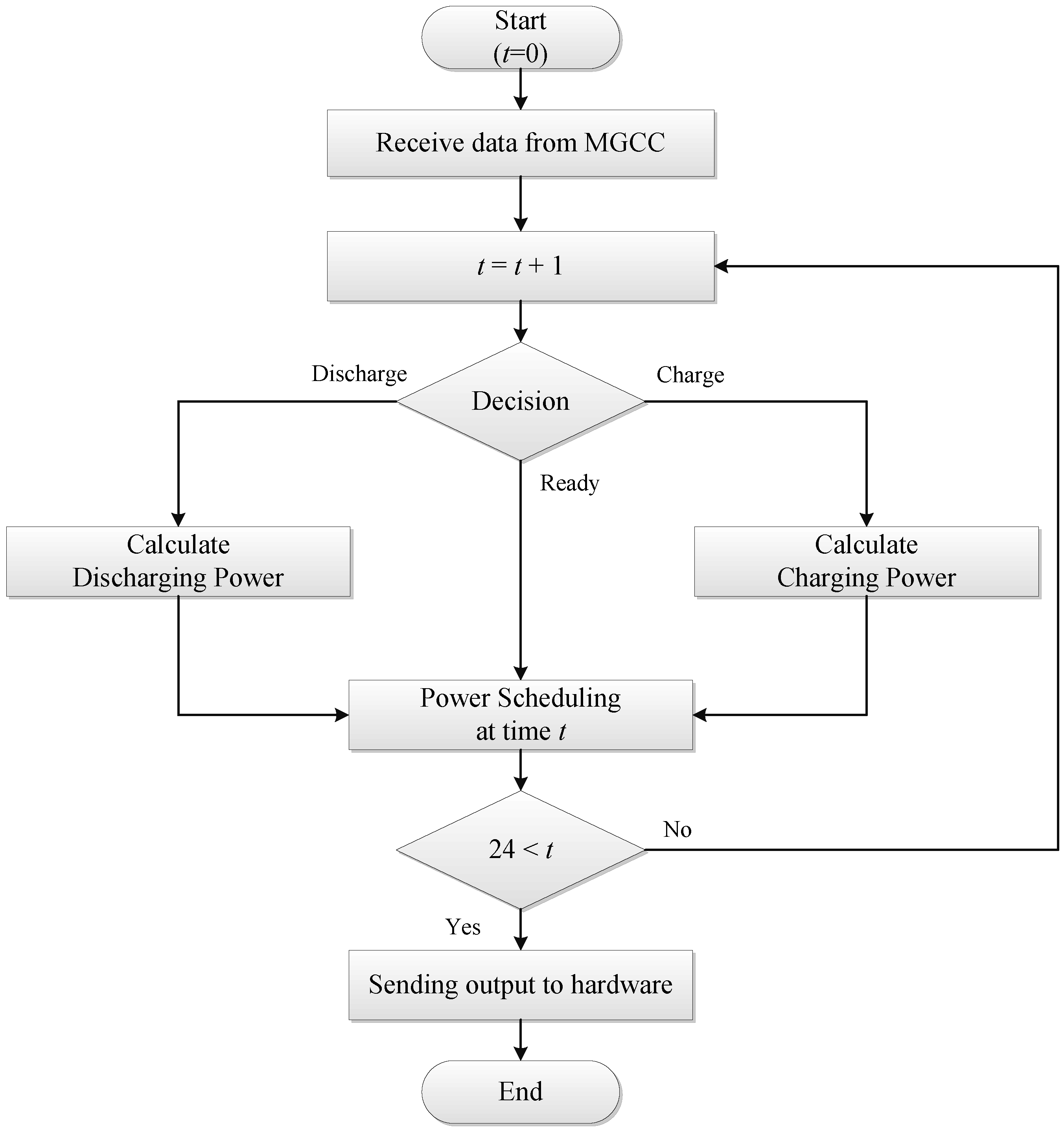
Figure 3 shows a flowchart of the BESS scheduling algorithm. The BESS has an agent that receives the electricity price from the MGCC. The agent determines the hourly BESS output using the fuzzy system with the hourly SOC and electricity price. In the scheduling algorithm, the BESS has a driving range of 30% to 100% of the SOC. When the calculated SOC is greater or lower than the operating range, the agent determines the maximum value within the SOC constraints. The defuzzification value from the fuzzy system determines the BESS power output. Depending on this output, it is possible to perform BESS scheduling over a 24 h period by repeatedly calculating the SOC of the next time.
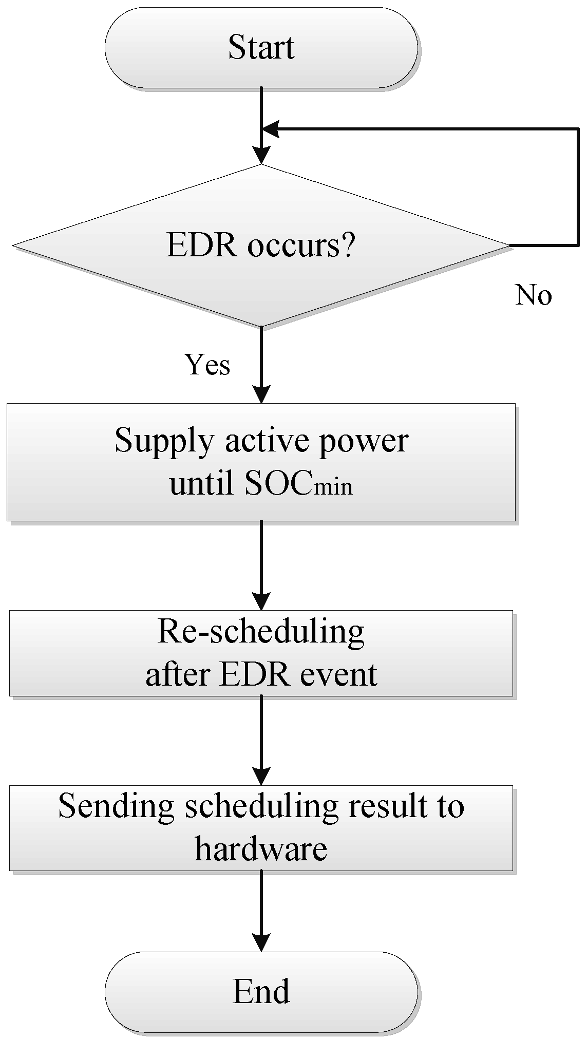
Figure 4 presents a flowchart of the real-time BESS operation algorithm. When the agent receives an emergency signal from the MGCC, the BESS discharges until an SOC of 20% is reached. After the EDR periods, the BESS performs rescheduling with the scheduling algorithm for the remaining time.
2.2. Algorithm for Intelligent Load Agent
It should be noted that the intelligent load in this study is assumed to be an industrial load for the manufacturing industry. An intelligent load consists of a controllable load that is controlled by the time, and a fixed load that is maintained at all times for the operation of a factory. In this paper, an intelligent load scheduling algorithm for DR is proposed considering the labor costs and the electricity price of the different time period from the authors’ previous study [
11]. In general, when a product is produced, its costs can be classified as the raw material costs, labor cost, electricity price, and other costs (transmission expense and external effect,
etc.). The raw material cost and other costs are fixed costs. Therefore, the labor cost and electricity price in each time period are important variables. Thus, the hourly production costs calculated by Equations (1) and (2) are used in the scheduling algorithm for the maximum benefit per day.
Figure 3.
Flow chart of battery energy storage system (BESS) scheduling algorithm.
Figure 3.
Flow chart of battery energy storage system (BESS) scheduling algorithm.
Figure 4.
Flow chart of BESS real-time algorithm.
Figure 4.
Flow chart of BESS real-time algorithm.
At each time, this can be expressed by the formula as follows Equations (1) and (2):
where:
: Product cost of each load type at time t;
: Raw material cost;
: Electricity price rate per product;
: Electricity price at time t;
: Labor cost rate per product;
: Labor cost at time t;
: Product’s selling price;
: Benefit between product price and cost.
Equation (1) represents the cost of the product, and Equation (2) represents the sale benefit per product. Finally, labor costs are classified as normal working hours, overtime working hours, and night working hours as listed in
Table 2.
Table 2.
Labor cost rate at each time period.
Table 2.
Labor cost rate at each time period.
| Time | AM. 8–PM. 6 | PM. 6–PM. 10 | Others |
|---|
| Normal Work | Extended Work | Night Work |
|---|
| Labor cost rate | 1 | 1.5 | 2 |
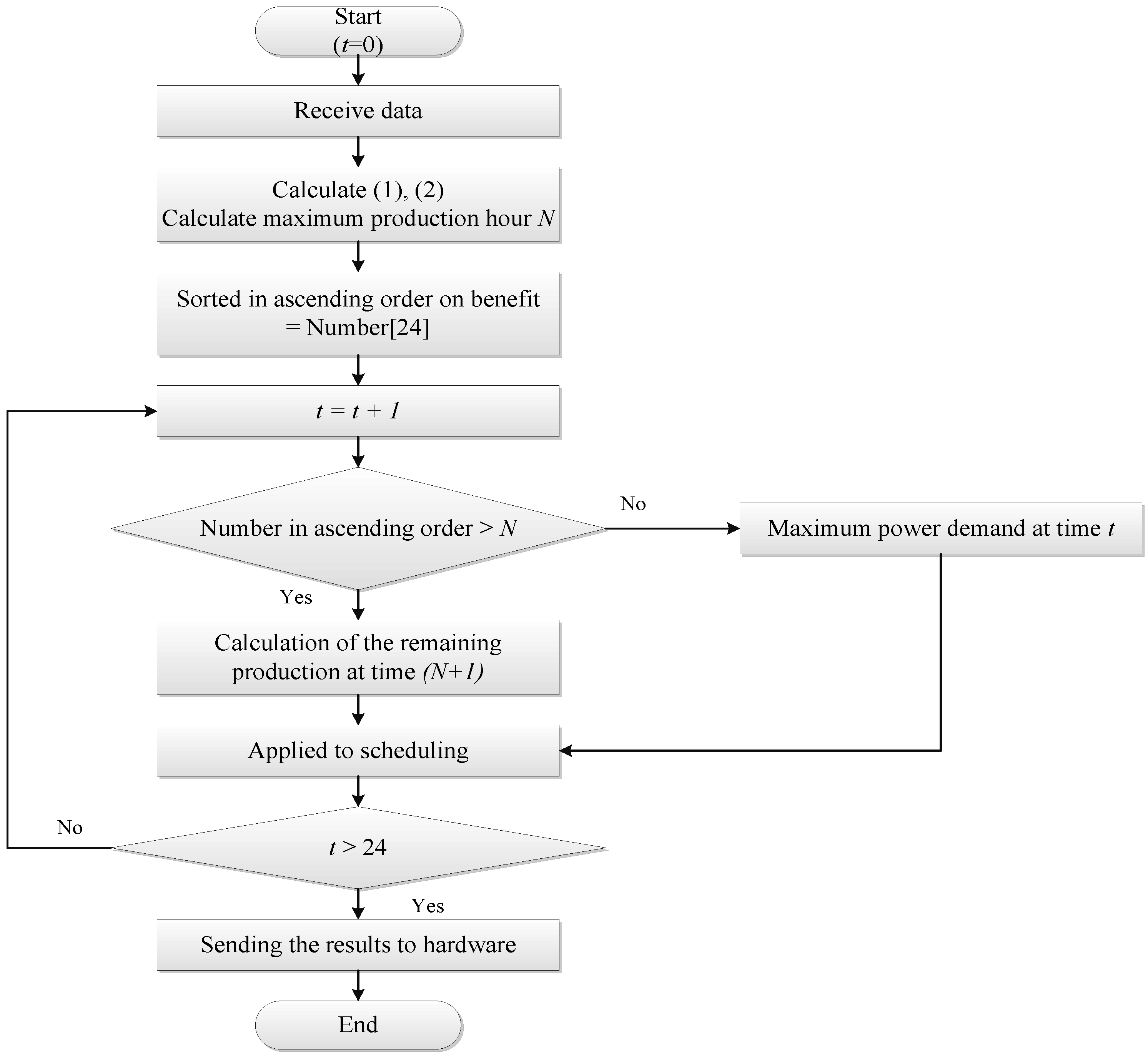
Figure 5 presents a flowchart for the intelligent load scheduling algorithm. The intelligent load agent received the electric price data of each time interval from the MGCC. The intelligent load agent calculates the production costs in Equation (1) and sorts them in ascending order. The intelligent load agent then uses the maximum power in order from the lowest cost of time. The remainder of the production volume after using the maximum power is used in the next time with low cost. When the scheduling algorithm is complete, the intelligent load agent sends data to the load hardware in chronological order.
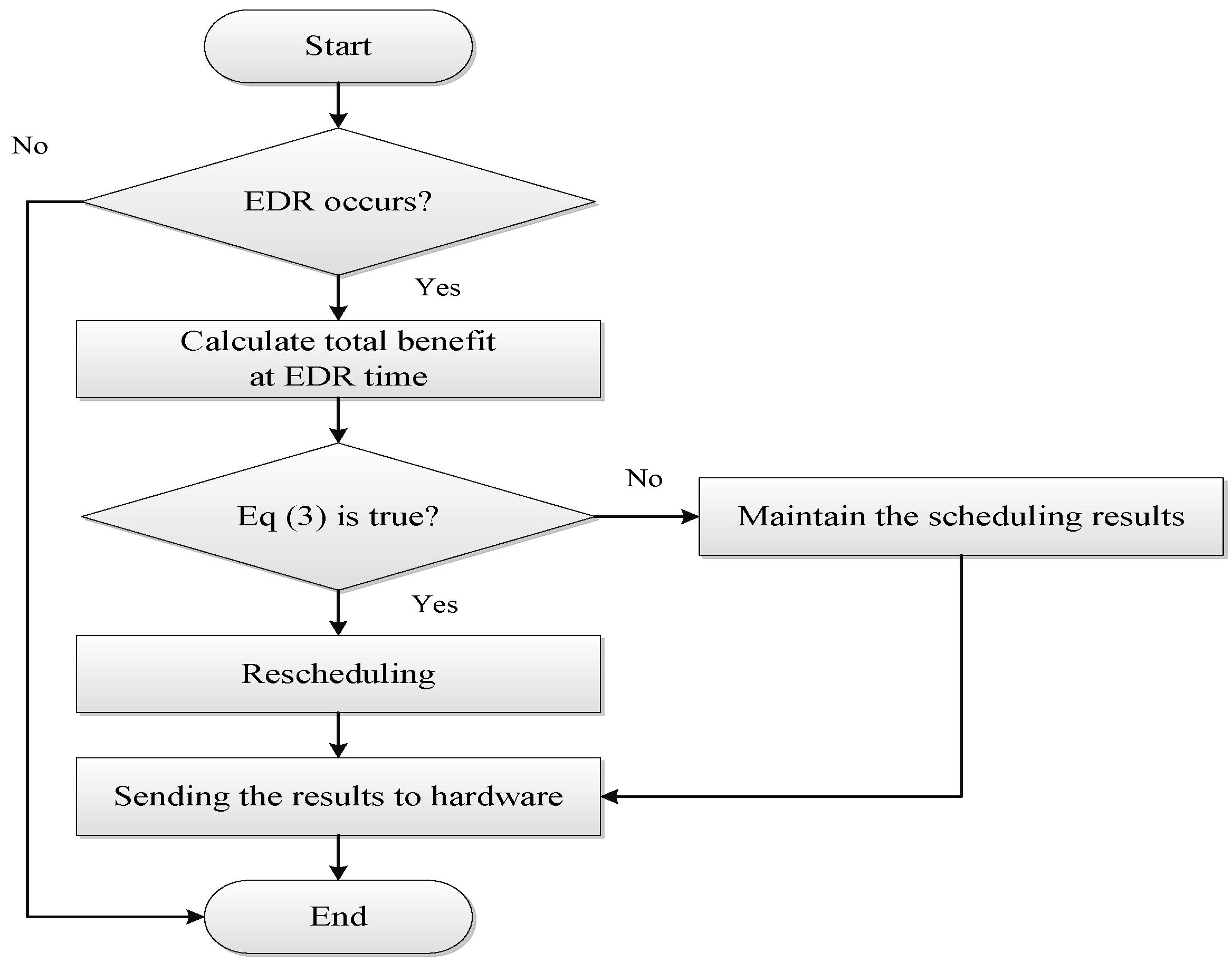
Figure 6 presents the flowchart of an intelligent load real-time operating algorithm. Initially, the daily schedule of the load is determined by the scheduling algorithm. The load agent verifies whether the signal is received from the MGCC before EDR occurs. The EDR signal has two data sets: (1) time period of EDR and (2) incentive by participating in EDR:
where:
: Incentive at time t;
: Controllable Power at time t;
: Load Power at time t.
In Equation (3), denotes the controllable power for manufacturing of products, and denotes the entire load power, which includes the controllable power and the fixed load for operating the factory. When the EDR signal is received at the load agent, the agent confirms Equation (3). If the equation is satisfied, the agent decides to participate in EDR. If the right-hand term is larger than the left-hand term in Equation (3), the agent retains the original scheduling. If the load participates in EDR, the agent reschedules for the elapsed time period of EDR in accordance with the scheduling algorithm. On the other hand, if the load does not participate in EDR, the load agent is affected by the scheduling algorithm. Here, it assumes that the power requirement at EDR is greater than the load. Therefore, all controllable loads except for the fixed load should be reduced in that time period.
Figure 5.
Flow chart of intelligent load scheduling algorithm.
Figure 5.
Flow chart of intelligent load scheduling algorithm.
Figure 6.
Flow chart of intelligent load real-time algorithm.
Figure 6.
Flow chart of intelligent load real-time algorithm.
2.3. Operation Algorithm for MGCC
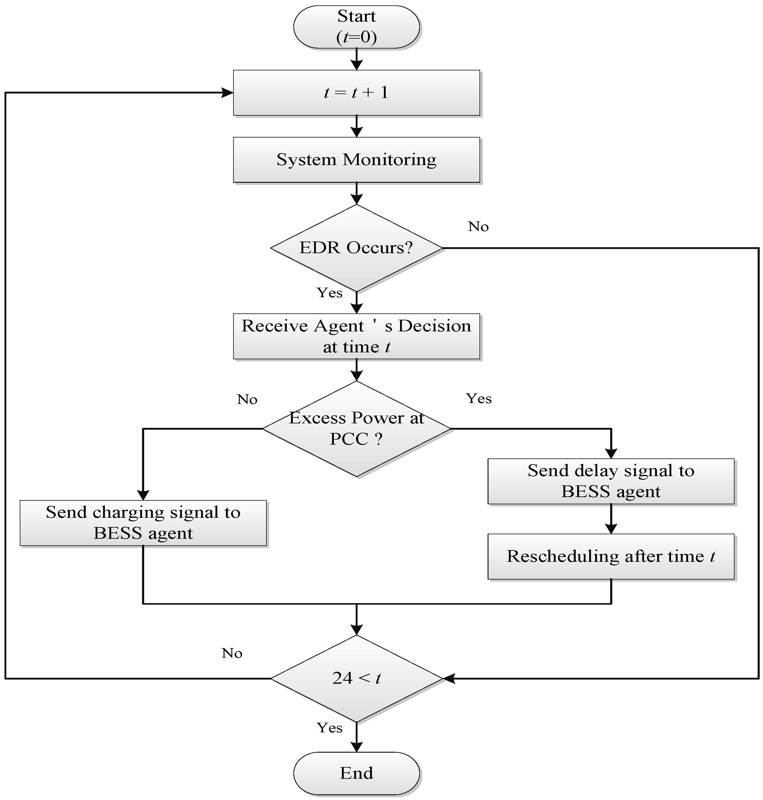
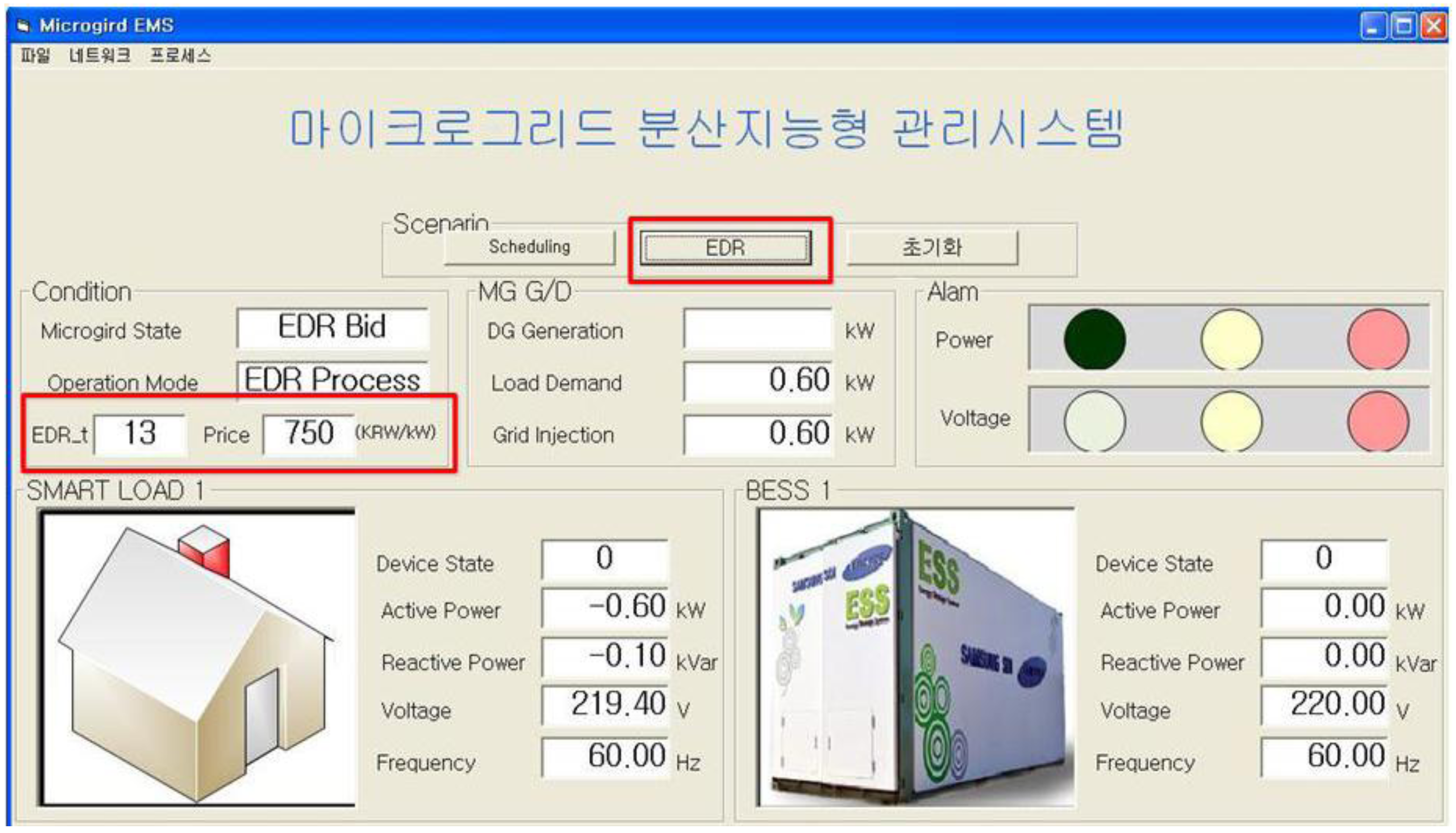
Figure 7 is the MGCC management algorithm considering the overall system stability. In general, the MGCC receives data (electricity price, emergency signal) from the upper EMS and sends this data and signal to lower agents. Further, the MGCC can monitor the power and control by sending any signal to the agents. In the grid-connected microgrid, however, problems such as the capacity of a transformer, transmission/distribution cable, and capacity of the PCC can occur. Considering these problems, the MGCC receives the expected charging power from the BESS agent, and if the total power in the microgrid exceeds the allowable value at the PCC, the MGCC sends a charging delay signal to the BESS agent. If not, the MGCC does not send a delay signal. The MGCC considers the power in the microgrid and the PCC capacity. Therefore, this system can be applied without other system changes if another DG or load is added to the system and the communication has been transmitted.
Figure 7.
Flow chart of microgrid central controller (MGCC) operation algorithm.
Figure 7.
Flow chart of microgrid central controller (MGCC) operation algorithm.
4. Experimental Results
This study simulated the intelligent distributed operation and control in the smartgrid environment that the new distribution simulator connects the BESS and the intelligent load. The new distribution simulator can monitor the state of microgrid and electricity quality from a remote PC connected to the Ethernet. The new distribution simulator can construct any power system network as setting in software installed in the PC and store real-time data from the installed power quality meter. On the other hand, because there is no feature that can see the graphically data display stored in the program, it can be compared graphically using the Excel program This study simulated intelligent distributed operation and control in a smart grid environment in which the new distribution simulator connects the BESS and the intelligent load. The new distribution simulator can monitor the state of the microgrid and the electricity quality from a remote PC connected to the Ethernet. The new distribution simulator can construct any power system network with suitable settings in software installed in the PC and store real-time data from the installed power quality meter. However, the program is unable to display stored data graphically. MS Excel can be used for a graphical comparison.
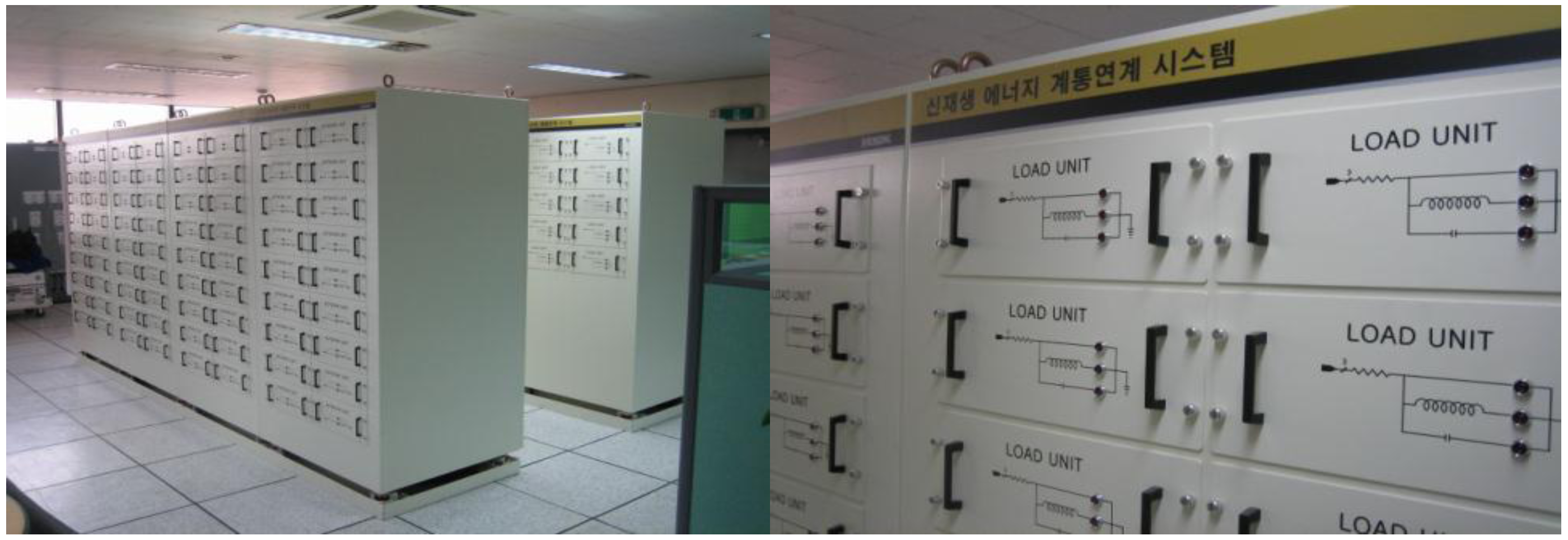
Figure 13 shows a distribution simulator for hardware test.
Figure 14 shows an intelligent load device and an energy storage device used in the hardware test. The two devices are connected to the new distribution simulator, and each device operates on the output from the connected agent. The inverter connected to the BESS and intelligent load has a rated capacity of 5 kW. The oscilloscope is installed at the point where the hardware is connected to the simulator for comparison with the PQM data in the software.
Figure 13.
New distribution simulator in the laboratory.
Figure 13.
New distribution simulator in the laboratory.
Figure 14.
Hardware for experiments (a) 5 kW BESS; (b) 5 kW Load.
Figure 14.
Hardware for experiments (a) 5 kW BESS; (b) 5 kW Load.
In this study, the hardware test was performed for scenario 1 and compared with the HILS test result. In the hardware test, it was difficult to visualize the electrical price and production costs, and the BESS SOC was calculated in the agent because of the simulation difference between the actual performance time of the BESS and the scaled time interval for simulation.
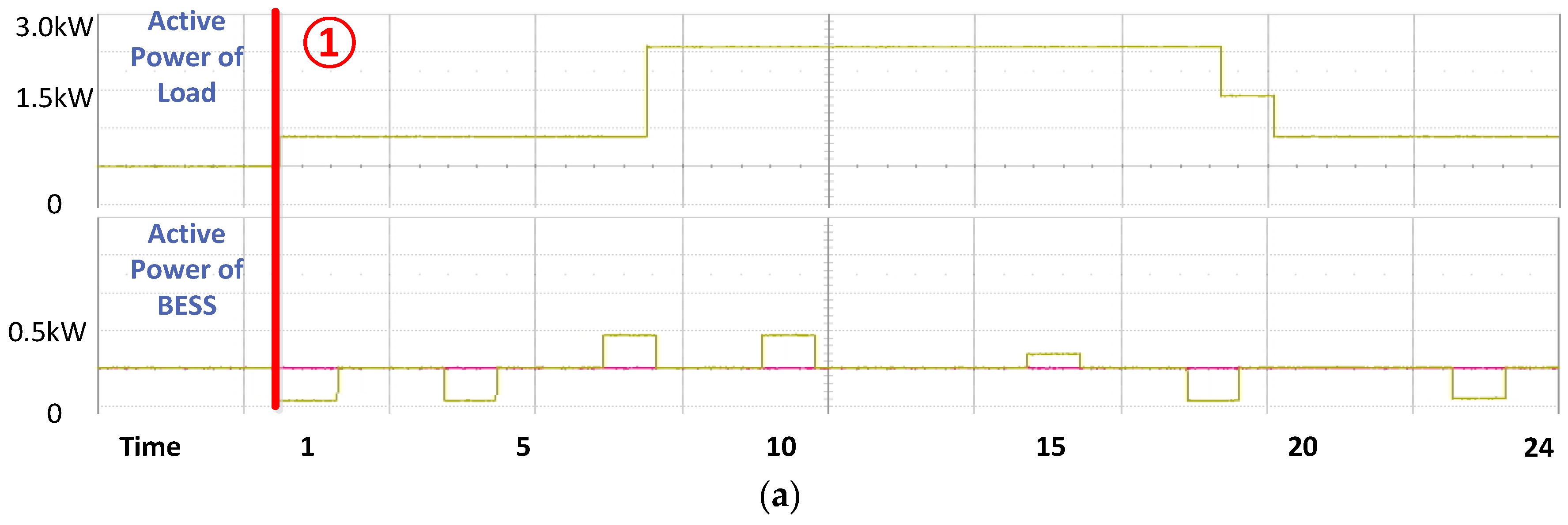
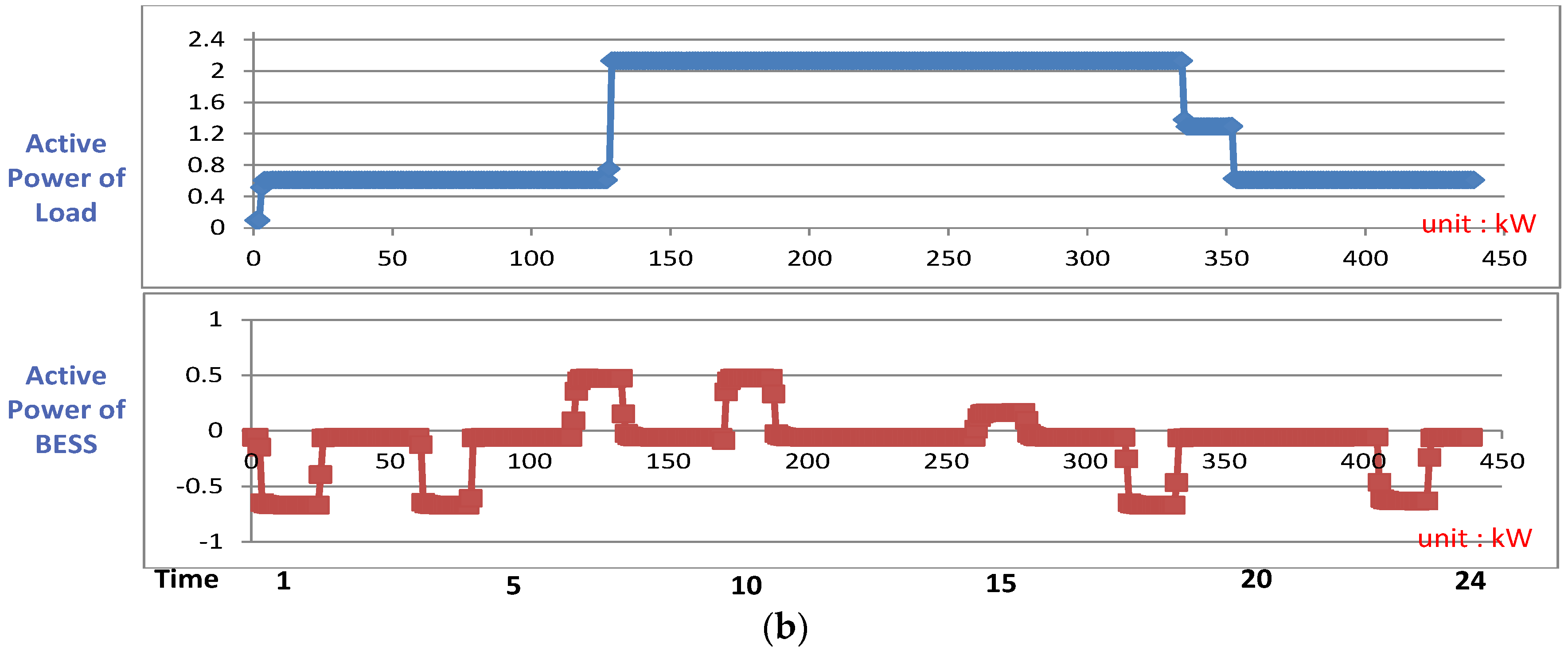
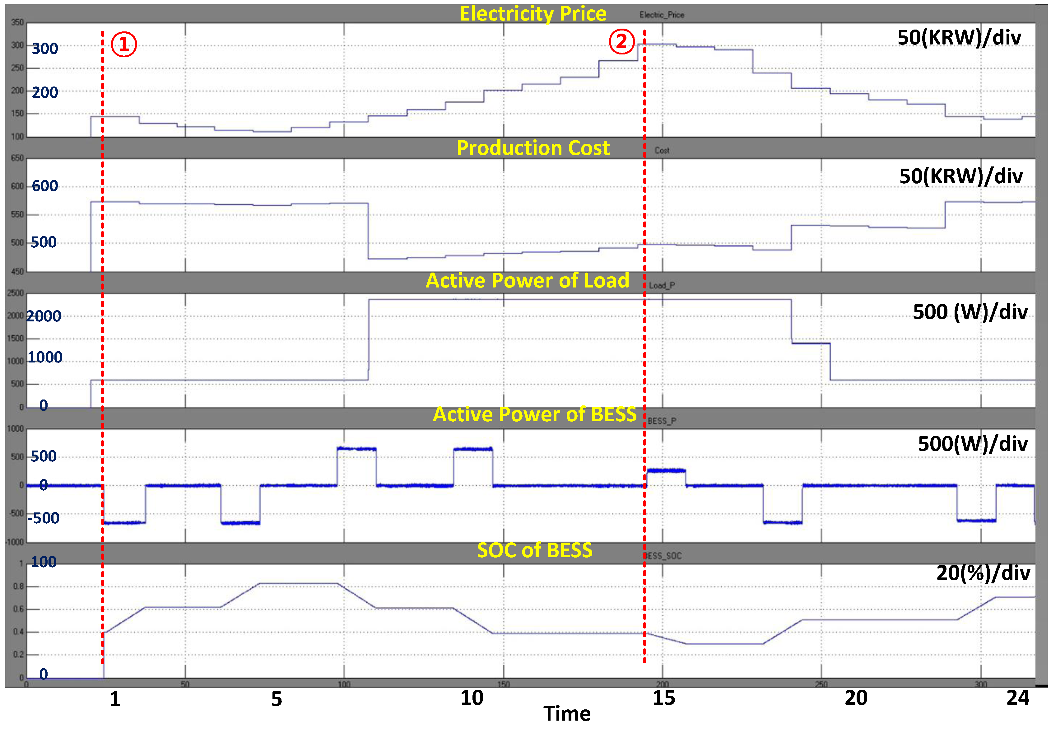
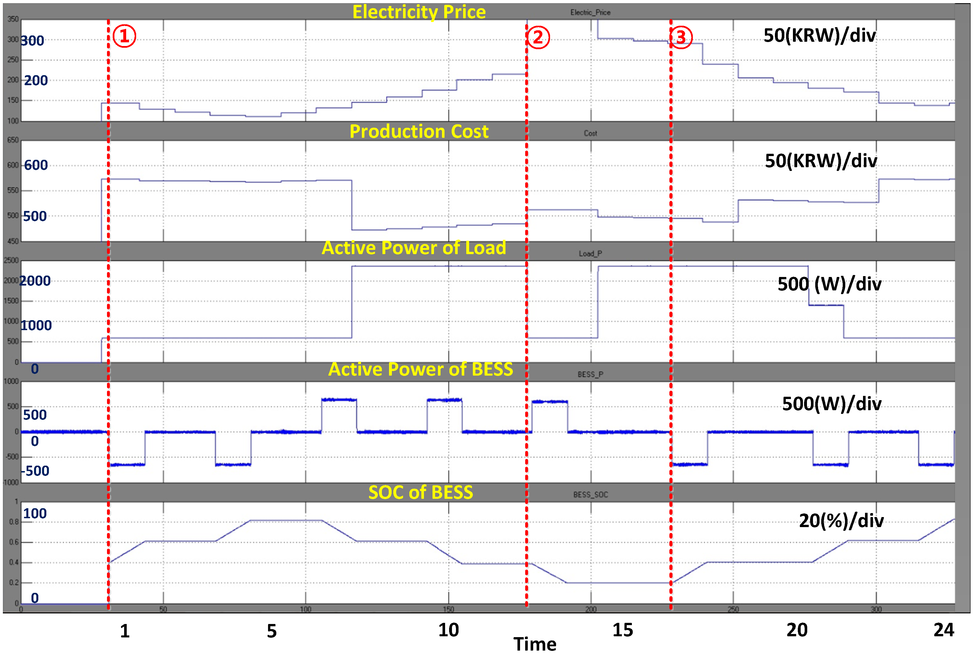
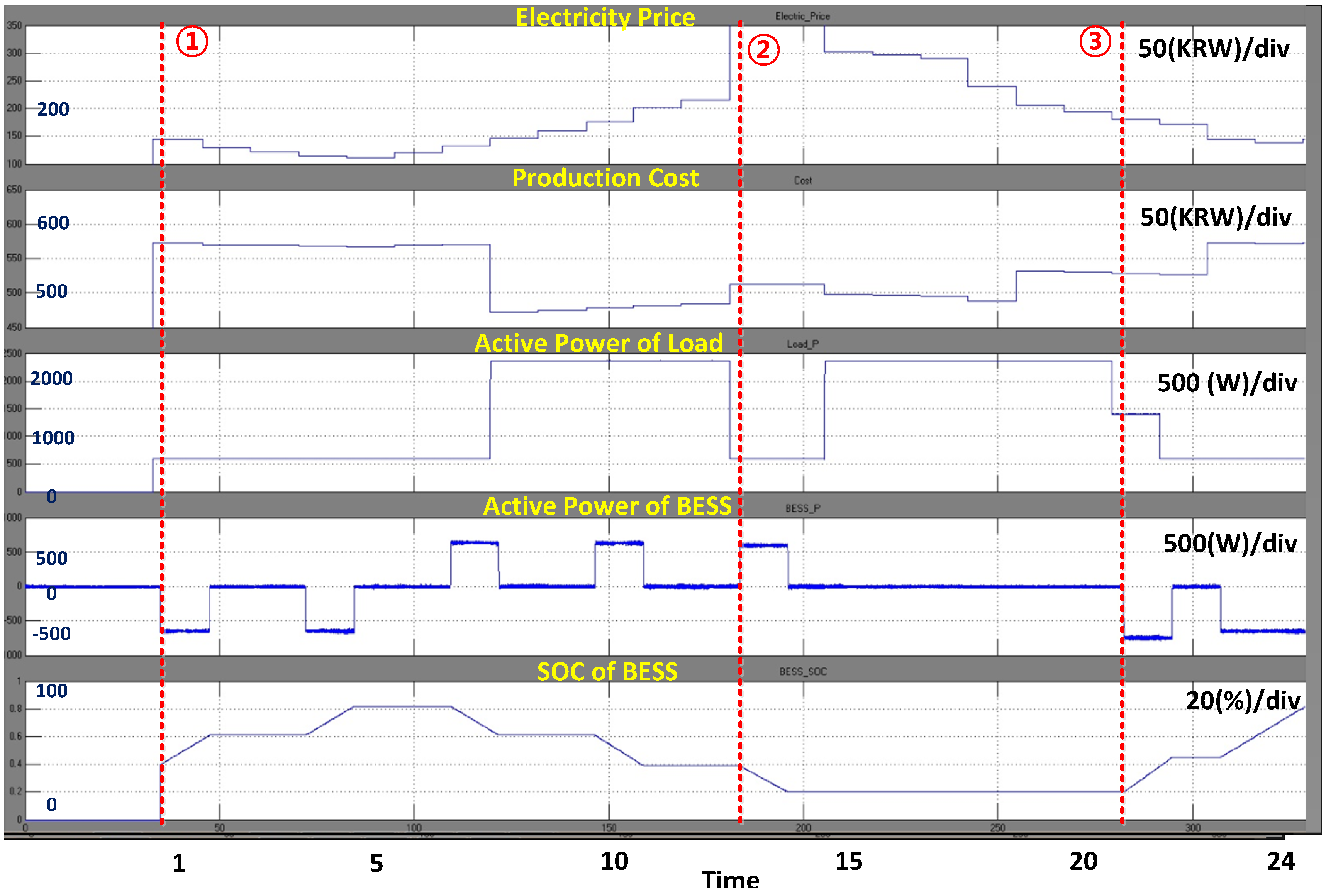
Figure 15 presents the HILS test result and the hardware test result for scenario 1. The two test results differ, but the overall charging and discharging and load patterns are the same. However, because of the difference between the scaled time interval and the actual time, a few milliseconds delay occurred owing to data transmission and calculation of the algorithm. If the system operates for one day, this problem can be solved by synchronization using a GPS system and other algorithms for solving the time delay problem.
Figure 15.
Hardware test result compared to the HILS test result of scenario 1 (a) Measurement at the oscilloscope installed in front of each piece of hardware; (b) Data stored in a new distribution simulator.
Figure 15.
Hardware test result compared to the HILS test result of scenario 1 (a) Measurement at the oscilloscope installed in front of each piece of hardware; (b) Data stored in a new distribution simulator.
5. Conclusions
This study examined the microgrid operation method using MAS. The agent, through a micro control unit and microgrid components, is constructed for a hardware test, and an operation algorithm is included for DR. The operation algorithm includes a scheduling algorithm and a real-time operation algorithm for emergency situations. The load agent schedules with the objective of minimizing the production cost by considering hourly electricity prices and labor costs. The BESS agent schedules by using a fuzzy algorithm. Because the BESS operation algorithm considers the hourly BESS SOC and the electricity price, the BESS maintains a constant SOC range to prepare for emergency situations.
Each agent in the microgrid operates for its individual benefit. The MGCC in the study does not control the output of the agent even if EDR occurs. However, although these individual operation strategies ensure the maximum benefit of each agent, they can be a problem from the system stability perspective because the agents do not have access to system information. Although the microgrid constructs distributed MAS, the MGCC’s role as a coordinator is required for monitoring and sending a grid’s signal and information to each agent.
Consequently, we verified that the microgrid system that includes each agent applied the proposed algorithms for the load and the BESS with the DR program. Further, this study not only simulates but also implements in HILS be employing a new distribution simulator through wireless communication. In a future study, agents corresponding to renewable sources such as a wind turbine will be included in this system. A more detailed scenario and operation strategy considering renewable energy sources will be developed.


