1. Introduction
Permanent magnet (PM) machines with high efficiency and high torque density have found extensive applications in various fields. Wide speed range constant-power operation is usually required in a variety of industrial applications such as in electric vehicles and wind power generation systems. Flux weakening-control of PM machines has been studied extensively by researchers [
1,
2]. The field-weakening performance of PM machines is usually limited by the magnet flux-linkage and the saliency ratio. For the machines without saliency effect, due to the uncontrollable PM flux, it is difficult to adjust the flux in the air-gap and realize field-weakening control. To improve the field-weakening capability of the PM machines, the hybrid excitation concept in which PM excitation and wound field excitation are combined together is investigated.
Li and Lipo [
3] proposed a new type of hybrid excited doubly salient PM machine capable of field weakening, which incorporates both PMs and wound field windings in the stator. Owing to the field winding, it has one hundred percent field weakening capability. The field windings are able to provide field-weakening characteristics even for machines without saliency. However, the shortcoming of this design is its relatively high cogging torque. Several other hybrid excitation synchronous machines have been proposed [
4,
5,
6,
7,
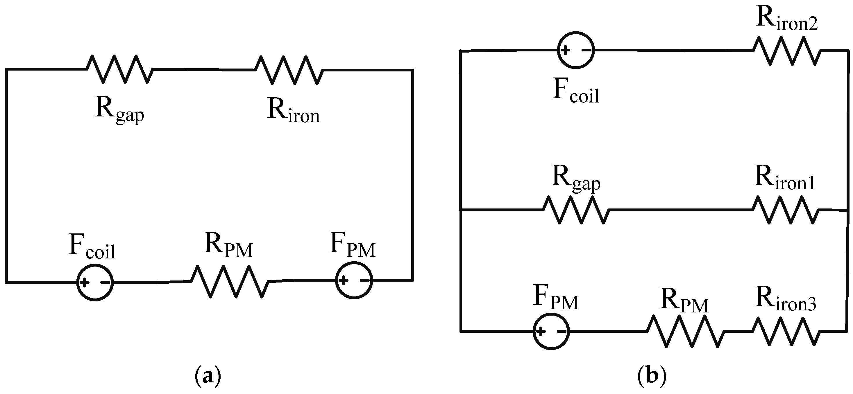
8]. Based on the former study, generally, the hybrid excitation machines is divided into two different types: series hybrid excitation machines and parallel hybrid excitation machines. To demonstrate the difference of two topologies, the basic equivalent magnetic circuit model is given in
Figure 1.
FPM and
Fcoil are the magnetic motive force (MMF) of the PM and excitation coils, respectively. R
PM and R
gap are the reluctance of the PM materials and air gap, respectively. In
Figure 1a,
Riron is the reluctance of the iron core, respectively. In
Figure 1b,
Riron1,
Rgap and
Riron are the reluctances of the PM materials, air gap and the iron core, respectively. The structure of the series hybrid excitation machines is simple. In these types of machines, the PM and the field control windings are in series. However, there are some disadvantages for these machines:
- (1)
Due to the low permeability of the PMs, the magnetic circuit of the excitation coil has a high magnetic reluctance; therefore, large ampere-turn excitation windings are needed to realize field weakening.
- (2)
The excitation coil is for field weakening only; the field-strengthening effect is poor because of the saturation of the iron core.
- (3)
The series topology may lead to the demagnetization of the PMs especially for the ferrite materials with low coercive force.
Figure 1.
(a) Series hybrid excitation machines; (b) parallel hybrid excitation machines.
Figure 1.
(a) Series hybrid excitation machines; (b) parallel hybrid excitation machines.
In parallel hybrid excitation machines, the PM is not in the magnetic circuit of the excitation coils. The excitation coils are not only for the field weakening but also for the field strengthening. The excitation current is much smaller because of the magnetic reluctance is lower.
The major problem of the hybrid excitation machine is that the field winding decreases the efficiency, worsens the heating problem and increases the size of the machine. To solve the heating problems of the hybrid excitation machines system level optimization [
9,
10,
11] should be considered. The core loss [
12,
13,
14] of the steels and cooper loss of the windings should be matched to improve the efficiency. Memory machine is an excellent alternative to prevent these problems [
14,
15]. The concept of memory is derived from the fact that the aluminum-nickel-cobalt (AlNiCo) materials can be easily magnetized by a temporary direct current (DC) current pulse and it was firstly proposed by Ostovic [
16]. In memory machines, with different DC current pulses, the field can be readily adjusted just as the hybrid excitation machines. Current pulse is injected into the DC winding during the operation of the machine with high current but very short time. Therefore the loss of the magnetization DC winding is very small and can almost be ignored.
In this paper, two novel structures are proposed. A hybrid excitation flux modulation machine (HEFMM) with DC field windings and AC armature windings is labeled as Machine A. The HEFMM has a bidirectional flux modulation feature. With the field modulation effect, HEFMM can realize the separation of the magnetic circuits of the PM and excitation coils. Therefore, it belongs to the parallel hybrid excitation machines. It has the significant merits of the parallel hybrid excitation machines. The flux modulation effect is applied in the magnetic gears first [
17,
18,
19,
20,
21,
22]. In HEFMM, there are two field modulation groups. The rotor PMs, inner stator tooth and AC power winding constitutes a field modulation group. The other field-modulation group is the DC field control winding, the rotor modulation steels and the AC power winding. For this design, the PMs are the major source of the air-gap flux. At low speeds, the DC current enhances the air-gap flux for high torque density. When the EMF (electromotive force) reaches its maximal value, the DC current will decrease to weaken the magnetic field. The DC winding is able to provide a reversing field to realize one hundred percent field-weakening. The DC field-weakening winding and AC power winding are distributed on two different stators. The DC windings located in the inner stator do not take the space of the AC power winding and do not obstruct the housing of the AC power winding.
Extending the study of HEFMM, a variable flux memory machine (VFMM) is investigated later and named as Machine B. In the VFMM, the DC field windings of the HEFMM are replaced by the AlNiCo PMs and DC magnetization windings. The AlNiCo PMs are magnetized by the current pulse of the DC windings housed on the inner stator and regulate the field to realize field weakening. The VFMM inherits the merits of HEFMM, which has excellent field weakening capacity and wide speed range. Furthermore, the VFMM improves the efficiency and power density dramatically. The principle of The HEFMM and VFMM is illustrated by analytical method. Time-stepping finite element method (TS-FEM) [
23] is used to simulate the steady performance of the novel machines. FEM simulation results are reported to validate the accuracy of the analytic model.
2. Operation Principle and Prototype Structure
2.1. Analysis of Flux Modulation Effect
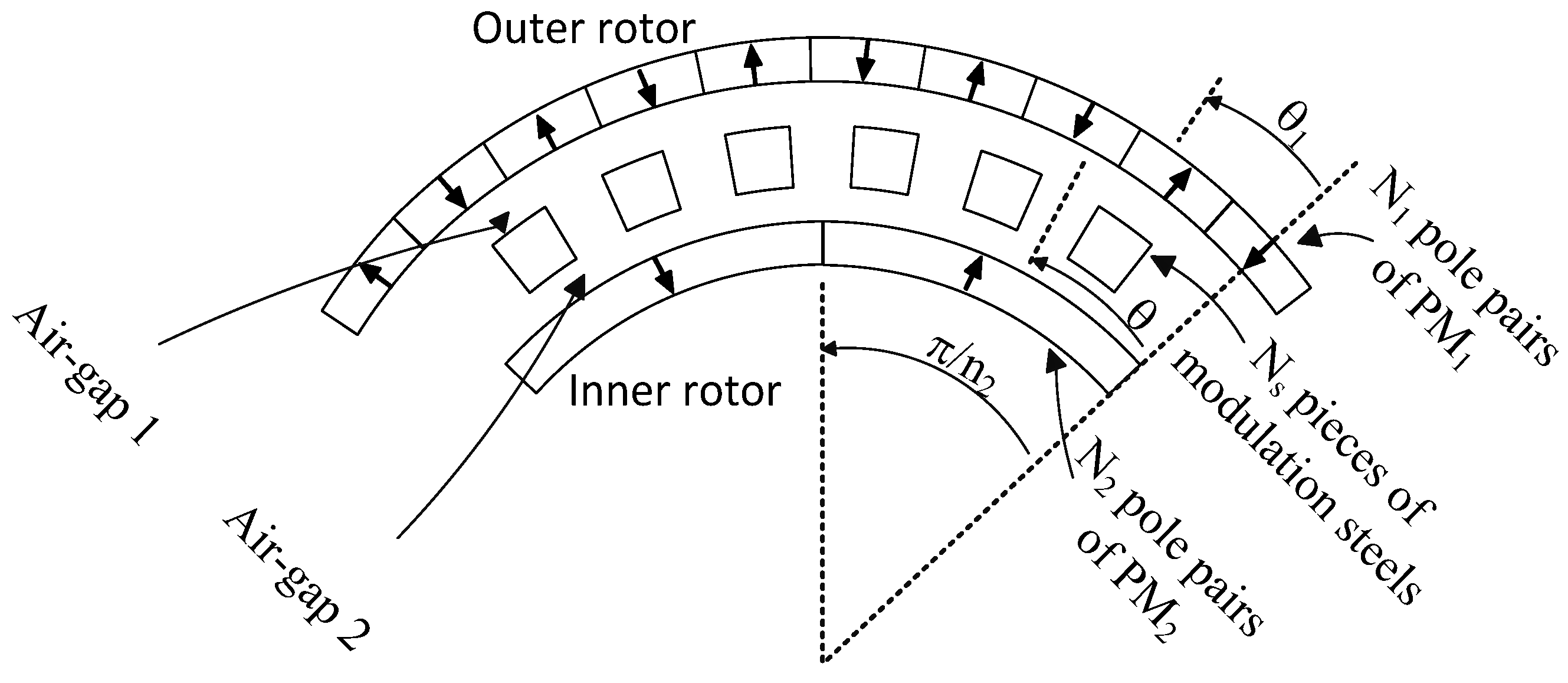
The basic idea of the flux modulation machine or Vernier machine is derived from the flux-modulation magnetic gear. The magnetic gear is shown in
Figure 2 and the air gaps are exaggerated. To illuminate the operation principle of the flux modulation effect, a portion of a magnetic gear is shown in
Figure 2.
Figure 2.
Portion of a flux modulation magnetic gear.
Figure 2.
Portion of a flux modulation magnetic gear.
The flux linkage excited by the outer rotor PM within one pole range of the inner rotor is examined.
N1 is the pole-pair number of the outer rotor PMs,
Ns is the pieces of modulation steels and
N2 is the pole-pair number of the inner rotor PMs. θ
1 is the outer rotor position and θ is the angular position in the outer air gap. The ω
1 is the mechanical speed of the outer rotor. The fundamental component of MMF of the outer rotor PMs F
PM1 and the magnetic circuit permeance
P are expressed as:
P1 is the permanence induced by the flux modulation effect of the modulation steels. Based on permeance coefficients expressions of the slot effect [
12], the
P0 and
P1 are given as:
where
ga1 and
ga2 are the thickness of the air gaps,
hm is the thickness and
Br is the residual flux density of PM
1.
c0 is space ratio of modulation steels. β is the nonlinear coefficient related to α and
ga1 + ga2 + hm. µ
0 is the vacuum permeability and µ
r is the relative permeability of PMs. According to Equations (1) and (2), the inner air gap flux density is shown as:
The flux linkage within one pole range of the inner rotor due to the outer rotor PM is given as:
When
N1 =
N2, the flux density due to the flux modulation effect is negligible and there is no gear effect between the two rotors. To employ the flux modulation effect, the pole pair numbers should satisfy the relationship
N1 − Ns = −N2. Equation (6) can be rewritten as:
For the flux modulation machine, the inner rotor PM poles are replaced by the stator windings. The stator flux linkage is same as the expression Equation (7) due to the flux modulation effect of the outer rotor PMs.
2.2. Dual Flux Modulation Effect
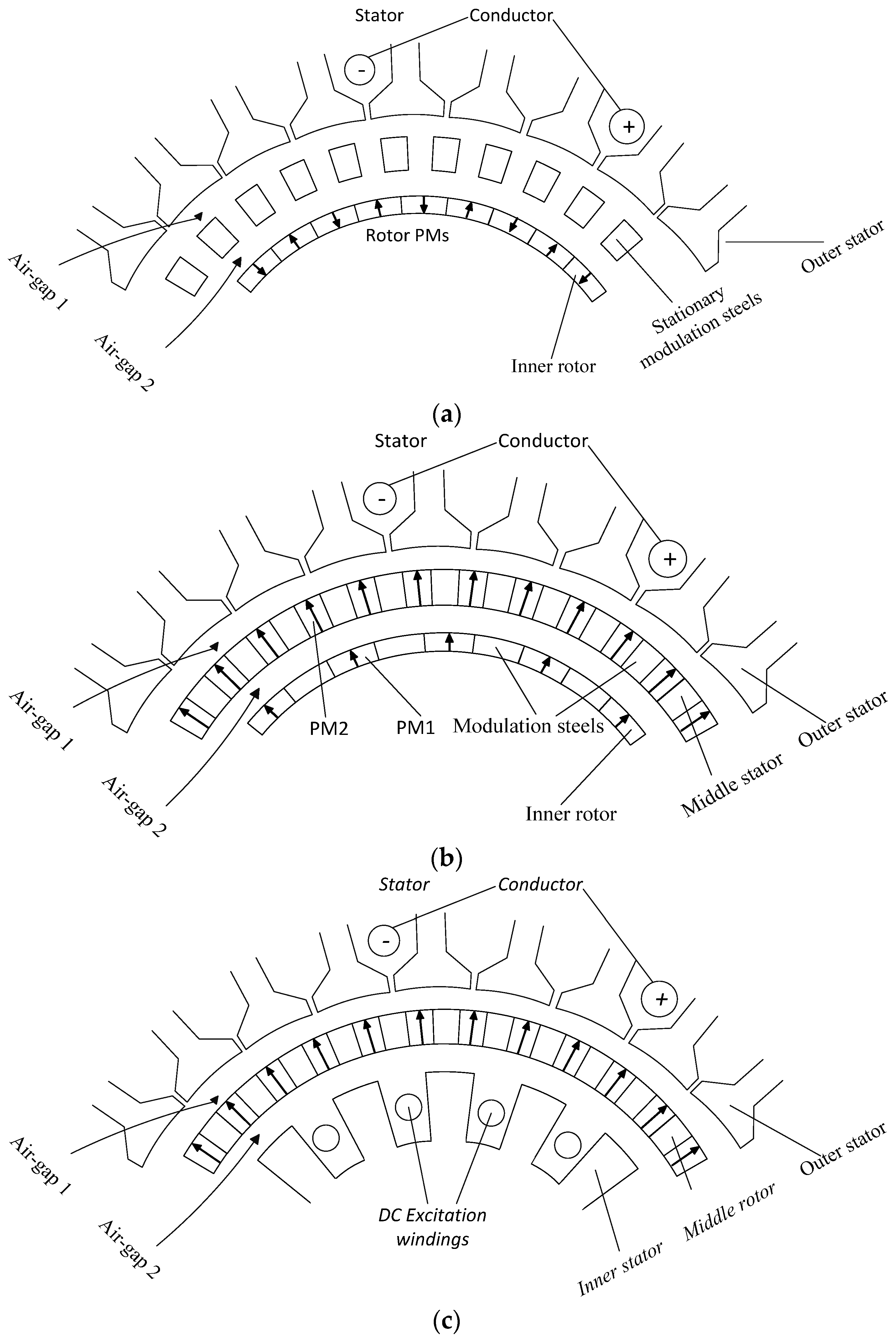
Compared with the conventional flux modulation machine, the dual flux modulation machine with two sets of PMs has much higher torque density. As shown in
Figure 3b, for the dual flux modulation machine, the rotor PMs are surface-inserted into the rotor yoke and additional PMs are inserted into the stationary modulation steels. The inner rotor PMs and the middle stationary modulation steels consist of the first set of flux modulation group. The rotor salient poles and the PMs inserted into the stationary modulation steels consists the second modulation group. The flux linkage of the stator winding is the superposition of these two fields and can be expressed as:
where Φ
PM1 is the flux linkage excited by the inner rotor PMs and Φ
PM2 is the flux linkage excited by the middle rotor PMs. To achieve preferable field control capability, hybrid excitation structure is shown in
Figure 3c. Instead of the inner PMs, the DC excitation windings can excite the field, which is modulated by the middle rotor steels. The scale of the magnetic field can be controlled by the DC current conveniently.
Figure 3.
Structure of flux modulation machine: (a) conventional flux modulation machine; (b) dual flux modulation machine; and (c) hybrid excitation flux modulation machine (HEFMM).
Figure 3.
Structure of flux modulation machine: (a) conventional flux modulation machine; (b) dual flux modulation machine; and (c) hybrid excitation flux modulation machine (HEFMM).
2.3. Variable Flux Memory Machine
The hybrid excitation dual flux modulation structure dramatically improves the field control capability of the flux modulation machine. However, the power consumption on the DC windings decreases the machine efficiency and increases the thermal load of the machine.
The VFMM with memory materials AlNiCo owns the excellent field control capability same as the hybrid excitation dual flux modulation machine and omits the power losses in the DC excitation windings. For the variable flux memory machine, the field regulation is realized by the AlNiCo PMs instead of DC field windings. Therefore, the number of pole pairs of the AlNiCo PMs is identical to the pole pairs of the DC field winding of the hybrid excitation dual flux modulation machine. Same as the deduction of the dual flux modulation effect, the effective flux in the air-gap of the VFMM can be written as:
The magnetization DC winding is powered by the current pulse at the beginning of the operation, the duty of the current pulse is very short, even though the transient current is quite high, the loss of this winding is low and the size of the DC magnetization winding is much smaller than the DC filed winding of the hybrid excitation dual flux modulation machine.
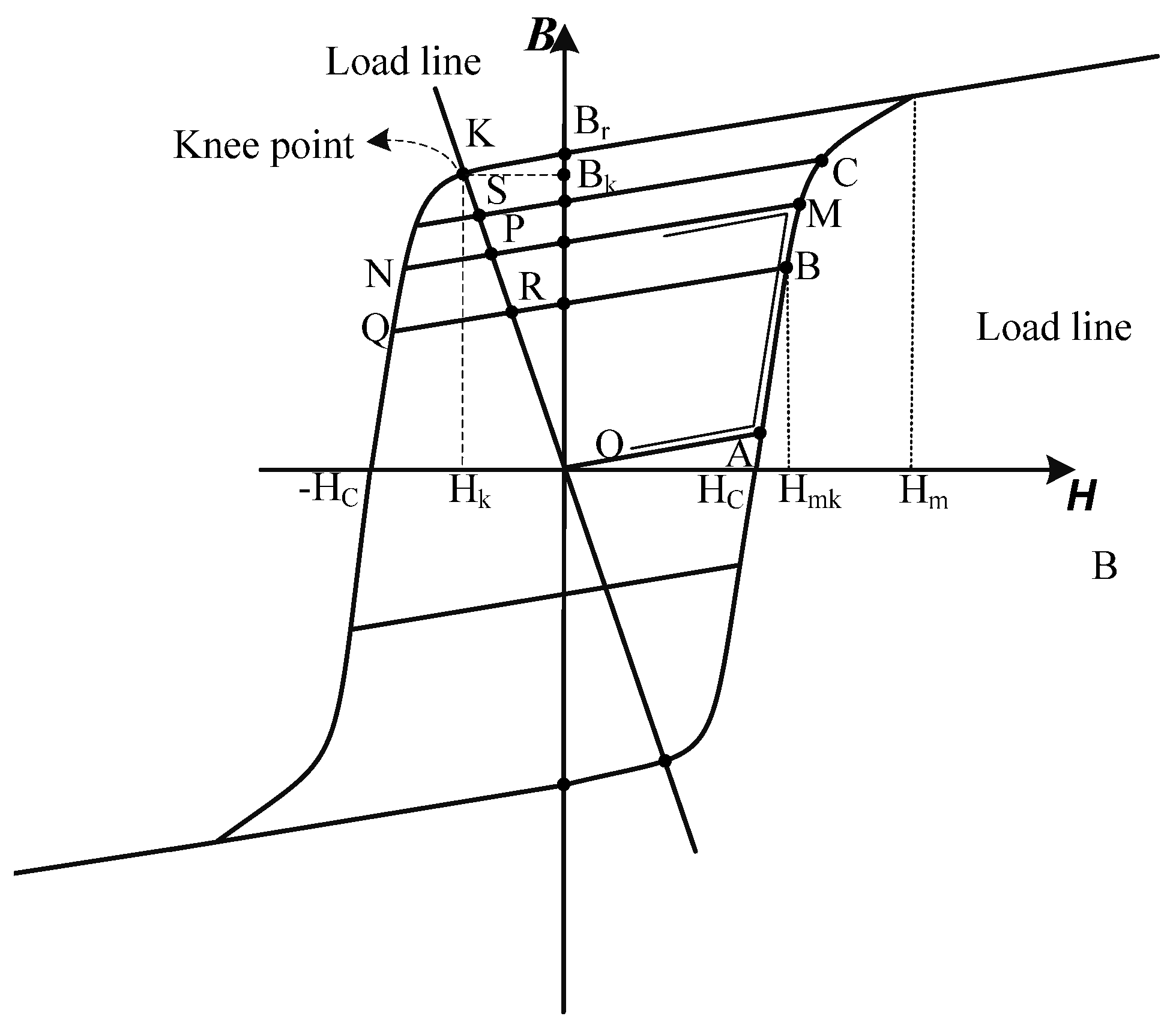
For the field weakening operation, the magnetization direction of the rotor PMs NdFeB is opposite with the AlNiCo material which are housed on the inner stator. The maximum magnetic energy product of NdFdB is much higher than the AlNiCo and the coercive force of the AlNiCo is low, therefore the demagnetization risk of the AlNiCo should be considered for the variable flux memory machine. To ensure that there is no demagnetization during the operation, AlNiCo should be thick enough. The working point should be above the knee point as shown in
Figure 4. B
r and
Hc are the remanent and coercive force of AlNiCo,
Bk and
Hk are the
B and
H value of the working point K, respectively.
Figure 4.
Nonlinearity-involved parallelogram hysteresis model of aluminum-nickel-cobalt (ALNiCo).
Figure 4.
Nonlinearity-involved parallelogram hysteresis model of aluminum-nickel-cobalt (ALNiCo).
By Ampere’ Law, the magnetic equation of VFMM can be written as:
where
hPM is the thickness of the AlNiCo
HL is the average value of the magnetic field intensity of the magnetic circuit outside the AlNiCo, and
lL is the length of the magnetic circuit. The section above the knee point of the
B-
H curve of AlNiCo is linear and the slope is μ
PM × μ
0. Therefore, the relationship between
Bk and
Hk is:
Substitute Equation (9) into Equation (8), the thickness of the AlNiCo PM is:
For the AlNiCo materials, to ensure the working point above the knee point, the
BK should be larger than 0.9 ×
Br. Therefore to avert the demagnetization of AlNiCo during the operation, the
hPM should be:
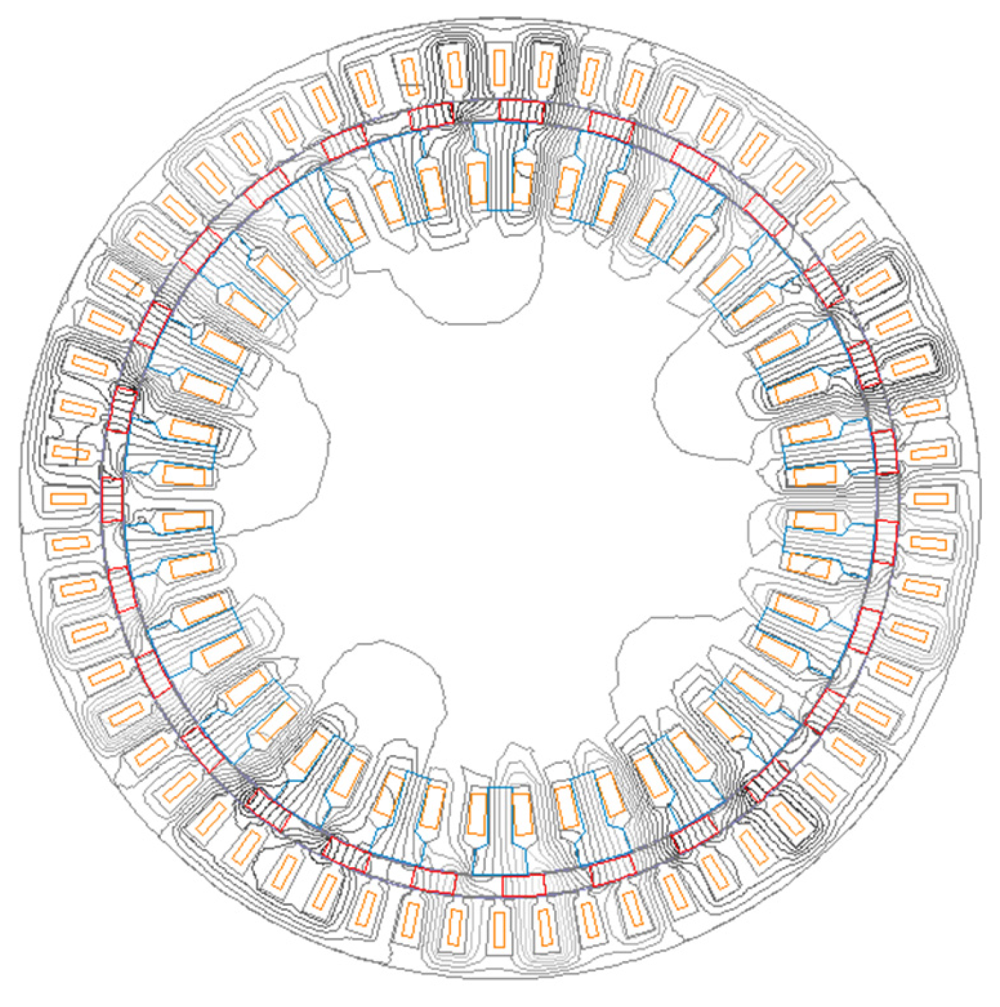
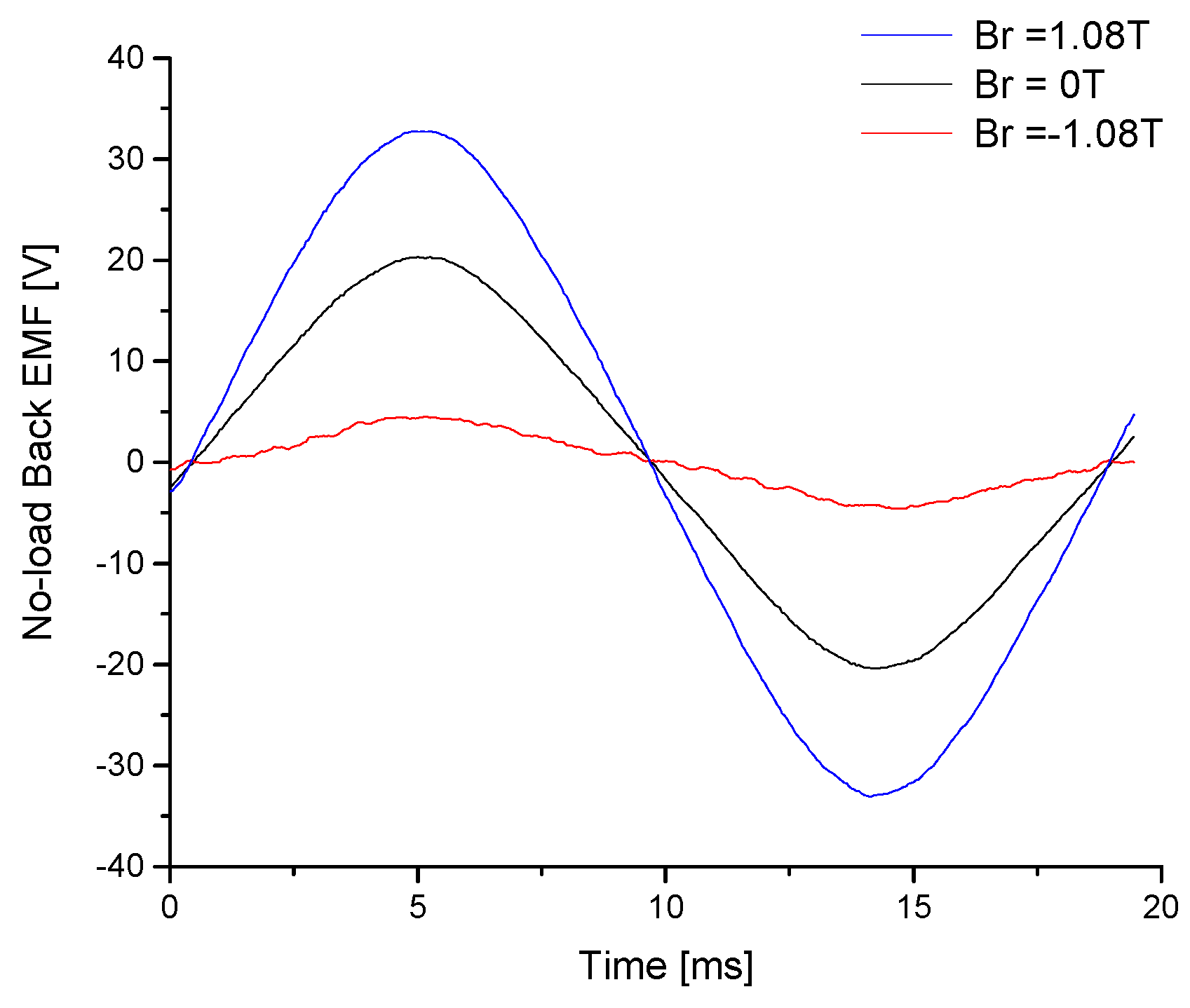
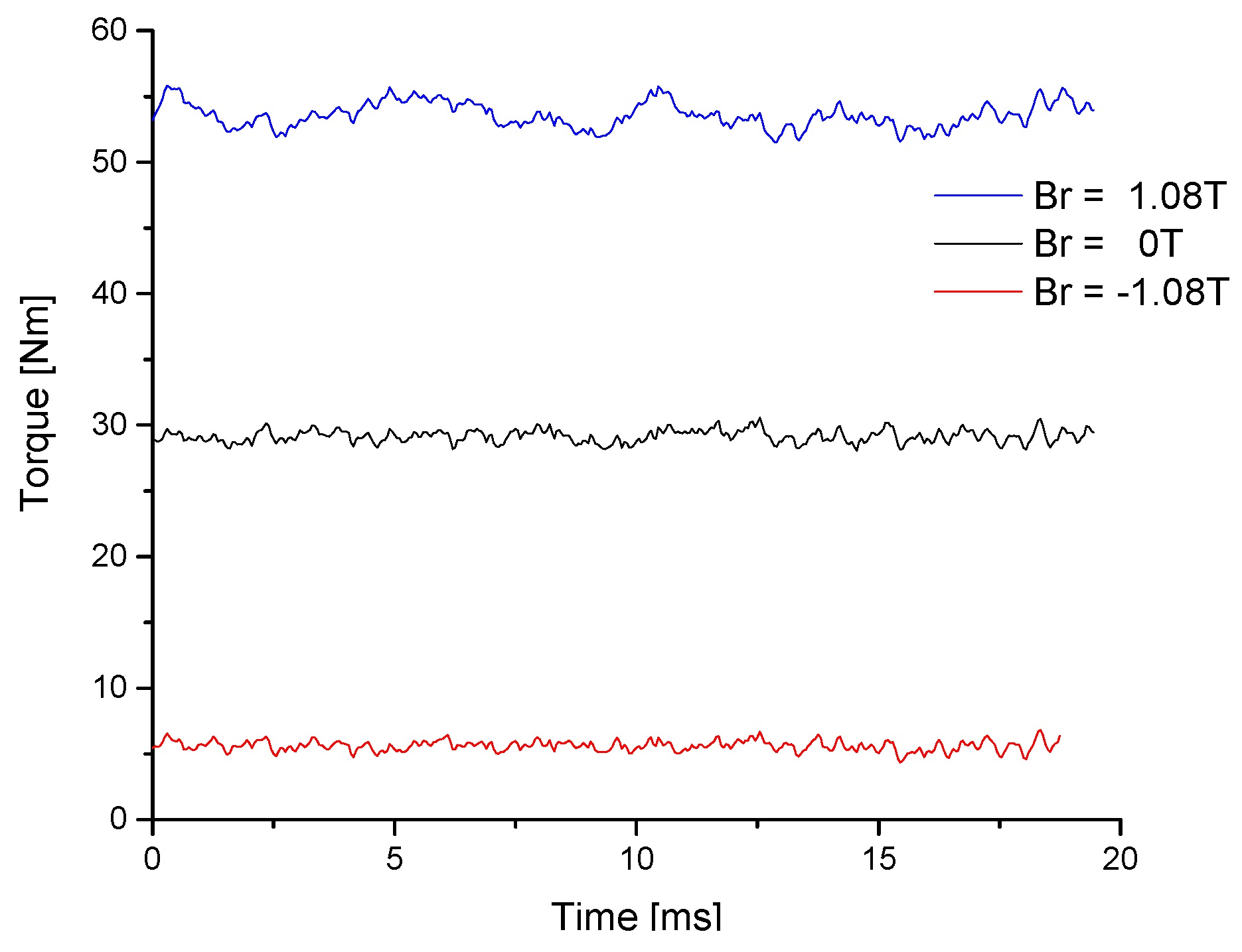
In the VFMM, field is regulated by the AlNiCo PMs, which is magnetized by the DC current pulse. To realize various degree of the field weakening for different speed, the remanent of the AlNiCo Br and the magnetization direction are determined by different magnetization or demagnetization DC current pulses applied in the DC windings. As analyzed above, the inner stator AlNiCo PMs enhance the field when the magnetization direction of the inner stator PMs AlNiCo and rotor PMs NdFeB are identical. Otherwise, they weaken the field when the magnetization directions are opposite.
2.4. Structures of Two Prototypes
For the prototype of HEFMM, Machine A, the AC power winding with five pole pairs is housed on the outer stator and DC field control winding with 22 pole-pairs is accommodated on the inner stator. Twenty-seven PMs magnetized in outward direction and 27 modulation steels are arranged radially on the rotor. In the HEFMM machine, the AC windings provide the rotating magnetic field, which is coupled with the lower speed of the PM rotor. HEFMM has two stators and one rotor.
For the prototype of VFMM, Machine B, the outer stator and middle rotor parameters are same as Machine A. The DC field control windings in Machine A are replaced by magnetization DC windings and AlNiCo poles. The structure parameters of Machine A and Machine B are shown in
Table 1.
Table 1.
Parameters of hybrid excitation flux modulation machine (HEFMM).
Table 1.
Parameters of hybrid excitation flux modulation machine (HEFMM).
| Parameters | Machine A | Machine B |
|---|
| Rated speed | 300 rpm | 300 rpm |
| Outer stator diameter | 200 mm | 200 mm |
| Inner rotor diameter | 75 mm | 75 mm |
| Axial length | 60 mm | 60 mm |
| Outer stator winding pole-pairs | 5 | 5 |
| Inner stator winding pole-pairs | 27 | - |
| Inner stator AlNiCo pole-pairs | - | 27 |
| Rotor pole-pairs (Pr) | 22 | 22 |
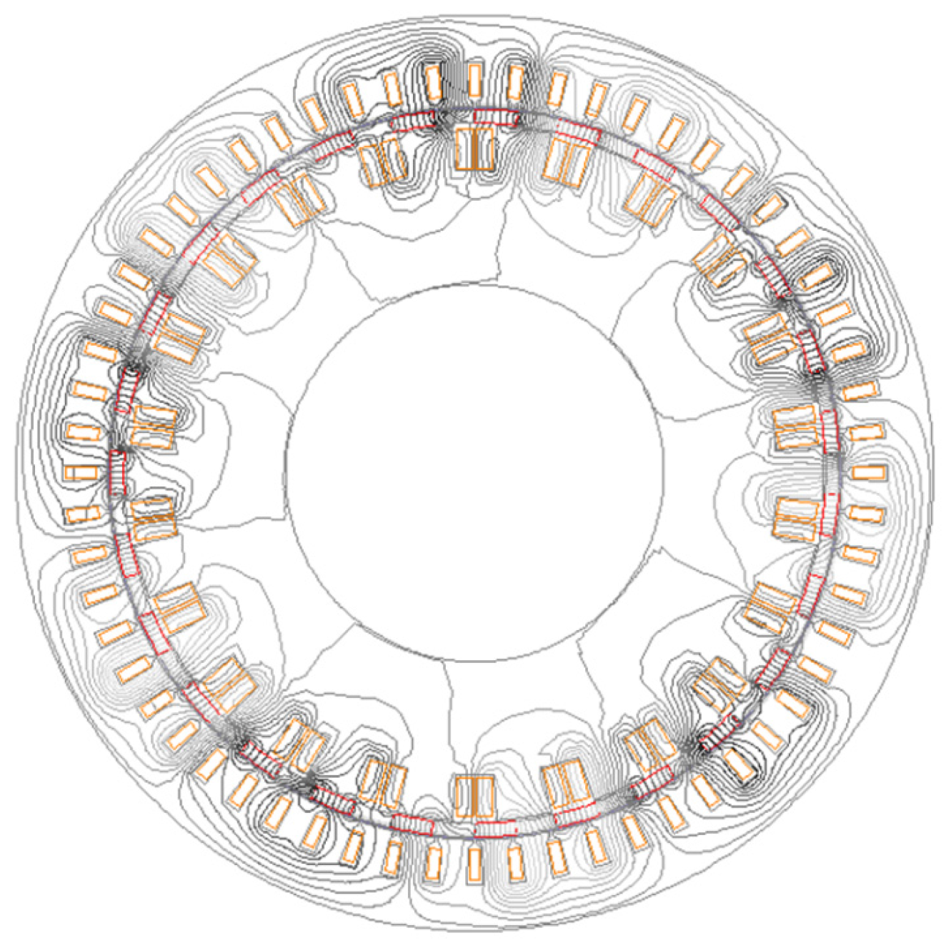
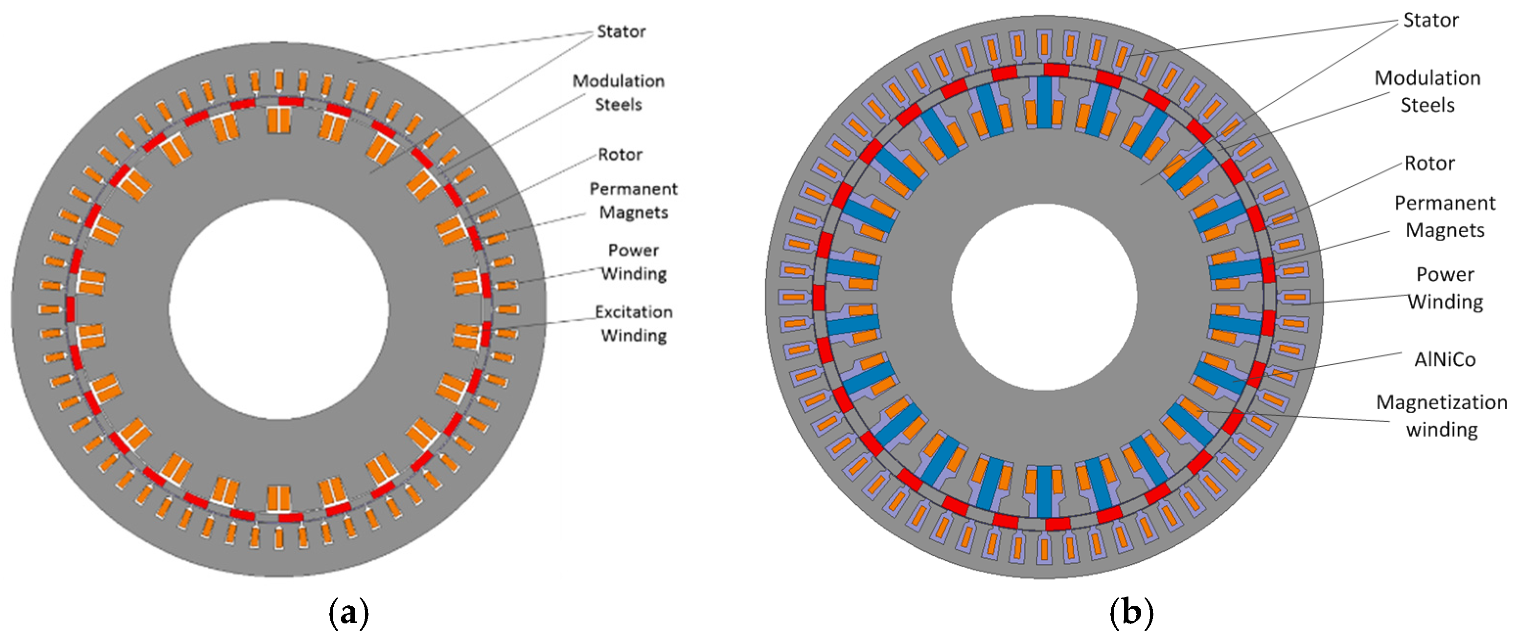
Figure 5a shows the structure of the proposed the HEFMM and
Figure 5b shows the VFMM. The major difference between these two structures is that each slot of the inner stator is inserted one piece of AlNiCo PM. The magnetization direction of the AlNiCo can be identical or opposite with magnetization direction of the rotor PMs. For Machine A, the DC field control windings are fed by continuous DC current to control the field. Therefore, the cooper losses are much larger than Machine B and the heating problem of Machine A is more serious than Machine B. The performance of the PM depends on temperature greatly. However, the two air-gap structure of these machines can improve the heat dissipation and high temperature PM material is used for Machine A. For Machine B, the inner windings are fed by pulse current and their cooper losses can be negligible.
Figure 5.
Structure of proposed machines: (a) HEFMM and (b) variable flux memory machine (VFMM).
Figure 5.
Structure of proposed machines: (a) HEFMM and (b) variable flux memory machine (VFMM).


