Article

Combustion Performance and Emission Characteristics of a Diesel Engine Using a Water-Emulsified Heavy Fuel Oil and Light Diesel Blend

Institute of Internal Combustion Engine, Dalian University of Technology, Dalian 116024, China
*
Author to whom correspondence should be addressed.
Energies 2015, 8(12), 13628-13640; https://doi.org/10.3390/en81212387
Submission received: 24 September 2015 / Revised: 10 November 2015 / Accepted: 24 November 2015 / Published: 1 December 2015

Abstract

:
Using low price heavy fuel oil (HFO) in high-speed diesel engines is a practical way to reduce running costs. However, most high-speed diesel engines’ fuel systems and combustion systems cannot adapt to HFO. This causes the problem of deterioration of combustion performance. In order to solve this problem, the authors have modified the fuel injection system and combustion system of a high-speed diesel engine to use HFO. In addition, reducing the viscosity of HFO is necessary before it is fed into the engine. Because heating apparatus are not feasible for high-speed engine users, light diesel was blended with HFO to reduce the fuel viscosity. The blend is called HFO-L. Meanwhile, for the purpose of further reducing NOx emissions and soot emissions, water-emulsified HFO-L, named HLW, was used on the research engine. When fueled with 10% water content HLW, the engine presented the same power performance and thermal efficiency as the baseline engine fueled with light diesel. Due to the low price of HFO, the fuel economy of the engine was greatly improved. In addition, fueling HLW led to a considerable reduction of the engine’s NOx emissions compared with the baseline engine.

1. Introduction

In developing countries, diesel engine users are very concerned about the running cost of their engines. Fuel expenses represent a major part of the running cost, so users are very sensitive to fuel price. Since heavy fuel oil (HFO) is much cheaper than light diesel, in recent years, a large number of diesel engine users, especially small ship owners, have sought to replace light diesel fuel with lower priced HFO to reduce their running costs, however, the original injection system and combustion system of high-speed diesel engines, which were designed to use light diesel, cannot accommodate HFO. Because of the characteristics of high viscosity, low evaporation rate and low ignition quality, directly using HFO would result in problems of deteriorated atomization quality, slow burning rate, and carbon accumulation, which not only impair the performance of a high-speed diesel engine, but also threaten the reliability of the engine [1]. Therefore, in order to burn HFO efficiently, it is necessary to modify the injection system and combustion system of high-speed diesel engines to adapt them to HFO, and take effective measures to change the characteristics of HFO.
Using HFO has problems of higher NOx and soot emissions compared with light diesel. This can be solved by using water emulsified fuel. Water is an effective additive for the reduction of NOx and soot emissions in combustion engines. In medium- and low-speed diesel engines, water can be directly injected into the cylinder to reduce the combustion temperature and thus reduce NOx emissions [2,3]. However, for small size high-speed engines, whose cylinder diameters are normally smaller than 140 mm, it is not practical to install a water injector on their cylinder head, therefore, for small size high-speed diesel engines, the only practical way is to use water emulsified fuel oil. There have been many research articles investigating the combustion performance and emission characteristics of diesel engines using water-emulsified light diesel fuel [4,5,6,7,8,9,10,11,12,13,14,15,16,17,18]. Some fundamental research on the combustion characteristics of HFO/water emulsions were carried out [19,20], but the effectiveness of emulsified HFO in high-speed diesel engines’ performance was seldom researched. In this paper, water emulsified HFO was used in a high-speed diesel engine, and the combustion performance and emission characteristics of the engine were studied. The object of the research is to lay out a roadmap for using HFO in a high speed diesel engine by a combination of fuel injection system and engine combustion system modifications and changing the characteristics of HFO.

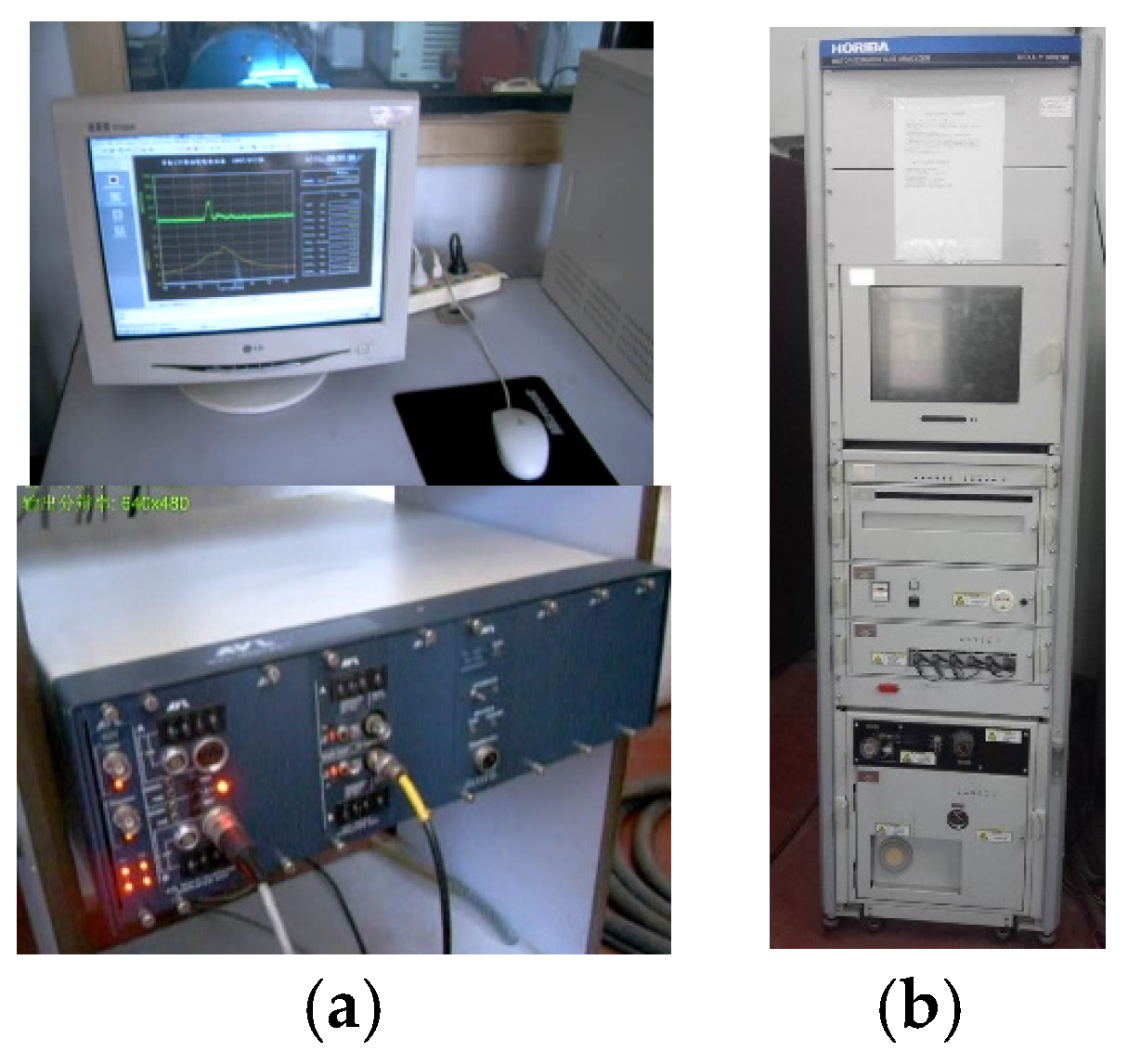
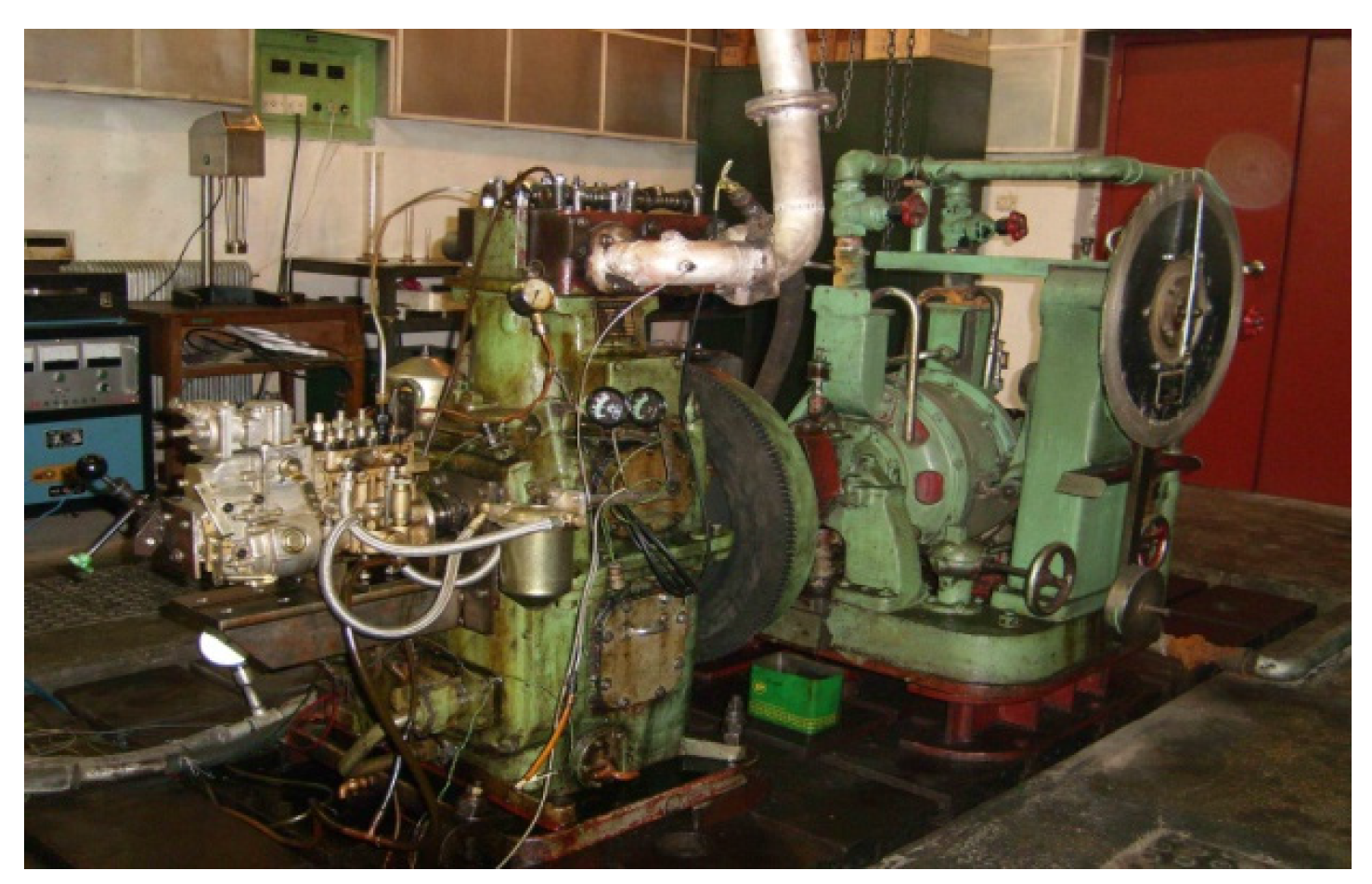
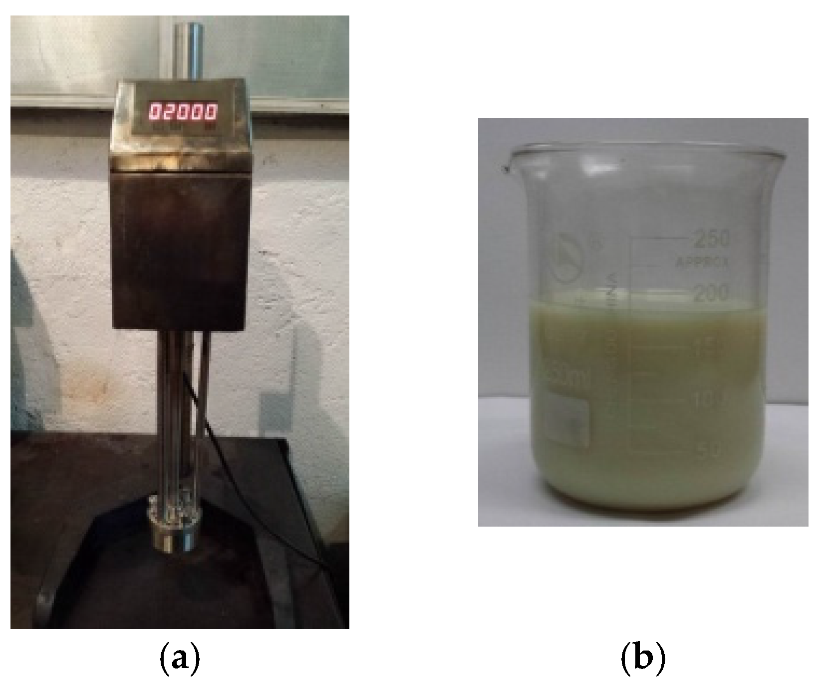
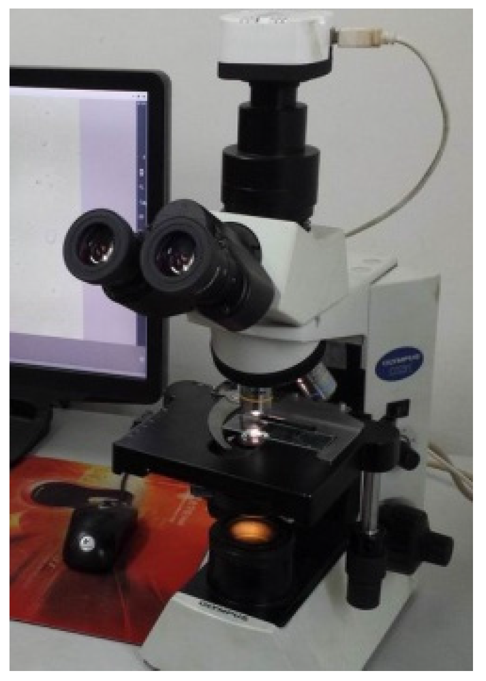
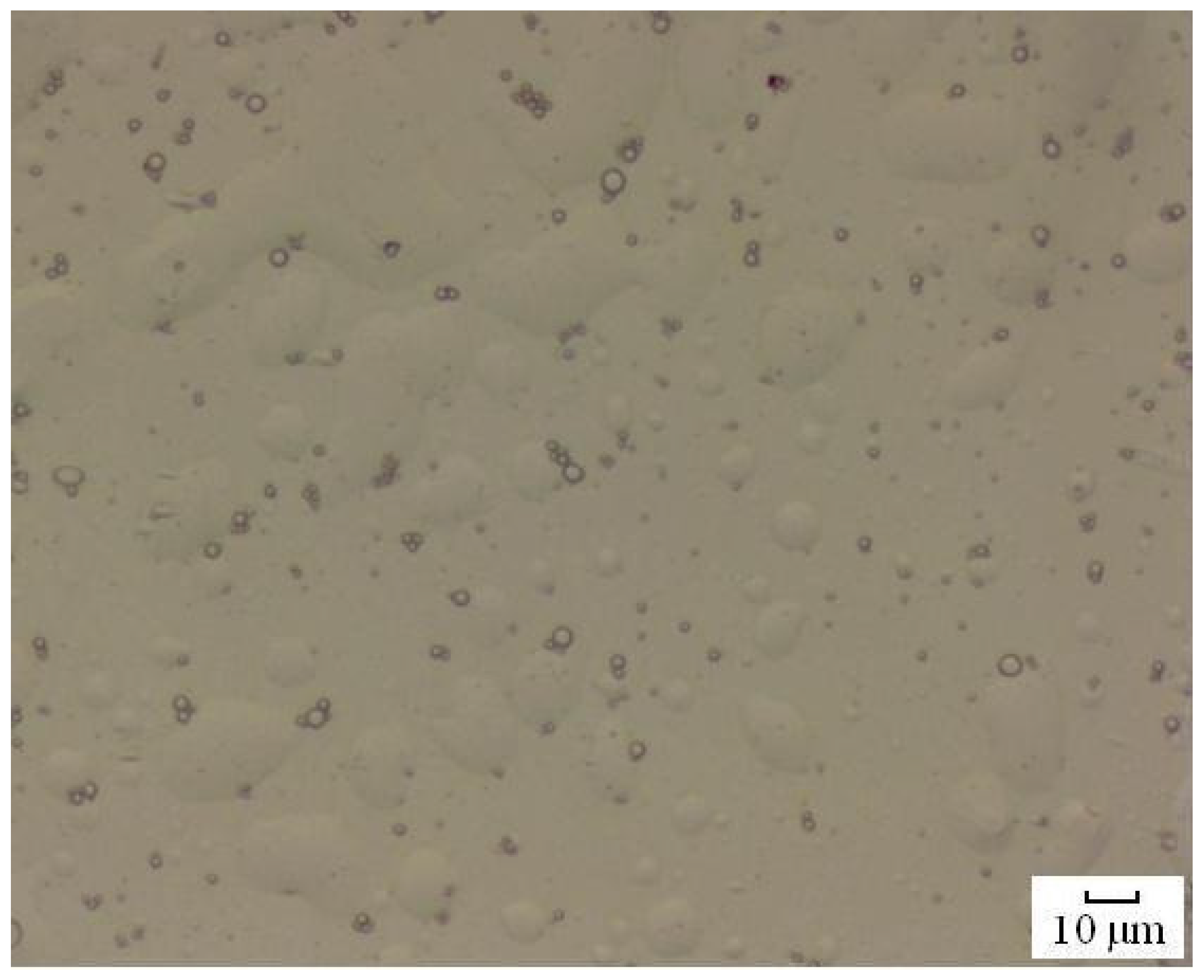
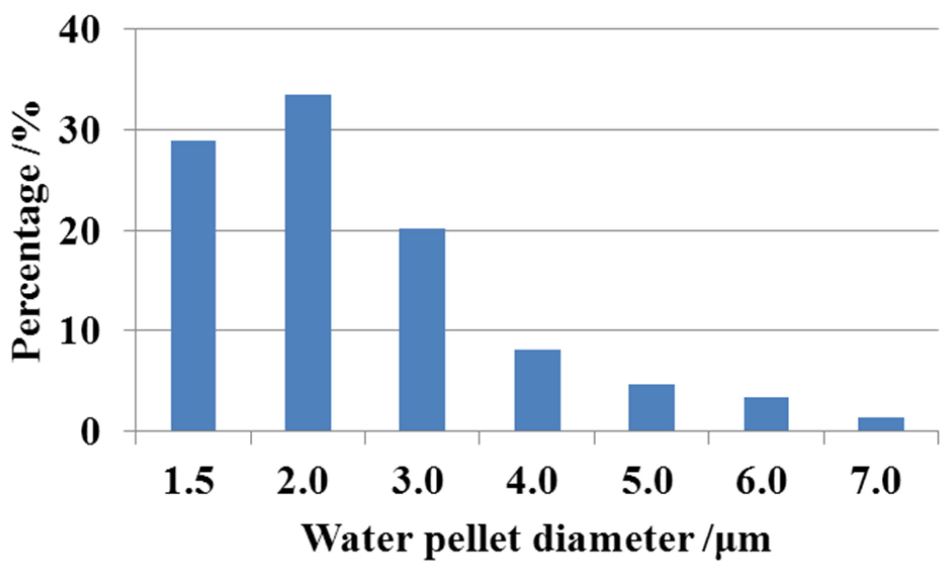
2. Experimental Setup and Procedure

A single cylinder naturally aspirated high speed diesel engine was used to study the combustion performance of the engine. The main parameters of the research engine are listed in Table 1. Figure 1 shows the research engine and its test bench.
Table 1. Main parameters of the research engine. °CA BTDC means crank angle degrees before top dead center.
ItemsUnitParameters
Cylinder bore × strokemm135 × 140
Compression ratio-17
Rated rotation speedr/min1500
Rated powerkW14.7
Fuel injection pressureMPa70
Fuel injection timing°CA BTDC12
Figure 1. The research engine and test bench.
Energies 08 12387 g001
The cylinder pressure curves were measured with an AVL Indiset 620 combustion analyzer (AVL LIST GmbH, Graz, Styria, Austria); the emissions were measured with a HORIBA 7100 exhaust gas analyzer (HORIBA Ltd., Fukuoka, Kyushu, Japan). Figure 2 shows these two apparatus. Table 2 presents the specification of the HORIBA 7100 (HORIBA Ltd., Fukuoka, Kyushu, Japan).
Figure 2. Major measurement apparatus: (a) AVL Indiset 620 combustion analyzer; (b) Horiba 7100 exhaust gas analyzer.
Energies 08 12387 g002
Table 2. Specifications of the HORIBA 7100 emission analyzer. Full scale: FS.
MeasurementRangeAccuracy
NOx0–10/50/100/200/500/1000/2000/5000/10,000 ppm≤0.5% FS
CO (low)0–50/200/1000/5000 ppm≤0.5% FS
CO (high)0–0.5/1/5/10 vol %≤0.5% FS
HC0–10/100/200/500/1000/2000/5000/10,000/50,000 ppmC≤0.5% FS
The authors modified a high-speed diesel engine’s fuel injection system to adopt high viscosity HFO, and used a new combustion chamber to facilitate the long penetration of HFO. Meanwhile, considering heating apparatus are not feasible in high-speed diesel engines, the authors blended light diesel fuel with HFO to decrease its viscosity. In this paper, this blend is called HFO-L. In HFO-L, the weight ratio of HFO to light diesel is 1:1. The fuel properties are listed in Table 3.
Table 3. Properties of HFO-L. HFO: heavy fuel oil; and HFO-L: HFO and light diesel blend.
PropertiesUnitLight DieselHFO-L
Density at 20 °Ckg/m3830890
Low heating valuekJ/kg42,50042,000
Kinematic viscosity at 20 °Cmm2/s410
Cetane number-4845
Sulphur content-0.18%0.3%
In order to compare the fuel economy of different fuel blends, an equivalent brake specific fuel consumption (BSFC) was defined. The equivalent BSFC is calculated by Equation (1):
b s f c Eq = b s f c M ( R H H u H + R L H u L ) / H u L
where R is the weight percentage of HFO or light diesel in the HFO-L fuel blend, Hu is the lower heating value, and the subscripts represent the following meanings: Eq—Equivalent, M—Measurement, H—HFO, L—Light diesel.
In order to adapt the engine to HFO-L, the authors modified the nozzle and the combustion chamber of the engine. With the new nozzle and combustion chamber, when using HFO-L, the NOx emissions are comparable to the prototype engine, but soot emissions are still higher. For the sake of reducing NOx emissions and soot emissions, water-emulsified HFO-L was used. According to the weight percentage of water in the HFO-L blend, five kinds of fuel blend were used. The fuel blend numbers and their meanings are listed in Table 4.
Table 4. The series of fuel blends used in the experiments. Water-emulsified HFO-L: HLW.
Blend NumberMeaningDensity (kg/m3)
HFO-LHFO-L blend without water.890
HLW08HFO-L blend with 8% of water.899
HLW10HFO-L blend with 10% of water.901
HLW12HFO-L blend with 12% of water.903
HLW15HFO-L blend with 15% of water.907
A stirrer was used to improve the emulsification. After 15 min stirring with a rotation speed of 2000 r/min, the emulsified fuel blend had a milky-white color. Figure 3 shows the stirrer and a photo of the water-emulsified HFO-L blend, which was taken seven days after the blend was made. With the aid of stirring and emulsification additives, the water-emulsified HFO-L blend can remain unseparated in two weeks. Visual water separation happens at the fourteen to fifteenth day after the blend was made, while the mean water pellet tends to increase during the water separation process.
Microphotos of emulsified HFO-L were taken by an electronic microscope (Olympus CX31 type (Olympus Corporation, Tokyo, Japan)). Figure 4 shows the microscope and Figure 5 presents a photograph of HLW10 under the microscope. It is a kind of water-in-oil emulsified fuel. With the aid of the image processing software ISCapture (Tucsen Photonics Co.,Ltd., Fuzhou, China) [21], the diameters of water pellets were measured and counted manually. The water pellet diameters range from 1.68 μm to 7.03 μm. The distribution of water pellet diameters is shown in Figure 6. It is indicated that 82.6% of water pellets are within a diameter range of 1.5 μm to 3.0 μm.
Figure 3. (a) The stirrer and (b) the water emulsified HFO-L.
Energies 08 12387 g003
Figure 4. The electronic microscope.
Energies 08 12387 g004
Figure 5. Microphotograph of HLW10. Water-emulsified HFO-L: HLW.
Energies 08 12387 g005
Figure 6. Water pellet diameter distribution.
Energies 08 12387 g006

3. Results and Analysis

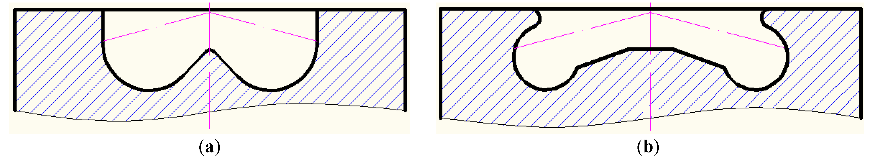
3.1. Effect of the Nozzle and Combustion Chamber Modification on Engine Performance

The baseline engine used a 6 × 0.3 (six holes with a hole diameter of 0.3 mm) nozzle, which did not adapt to high viscosity HFO-L. Therefore, when the prototype engine was fueled with HFO-L, the BSFC and soot emissions were apparently higher than the baseline engine fueled with light diesel. This is unacceptable to engine users. For instance, under rated power conditions, the BSFC of HFO-L was 241 g/kW·h, or 21 g/kW·h higher than the baseline. Moreover, the reliability was deteriorated due to choking and fuel coking of the nozzle. In order to solve these problem, the nozzle was changed from 6 × 0.3 to a 4 × 0.36 (four holes with a hole diameter of 0.36 mm) type. With the bigger hole diameter, the new nozzle’s flow area of a single hole is bigger and accordingly the flow rate of a single hole is increased compared to the prototype nozzle. Thus the problem of fuel flow choking is avoided. With the new nozzle, when using HFO-L, engine working stability was ensured. After 400 running hours, the nozzle still worked normally without choking and fuel coking, and the power performance of the engine remained the same as the prototype engine fueled with light diesel.
Considering the longer penetration of HFO-L compared with light diesel, for the purpose of avoiding too much impingement and fuel adhesion on combustion chamber walls, the combustion chamber shape was modified. Figure 7 shows the comparison of the prototype piston head and modified piston head. The modified chamber has a bigger inner chamber space than the prototype chamber. As shown in Figure 7, at the time of combustion TDC, along the fuel spray centerline, the distance from the nozzle hole to the chamber wall is defined as L. The distance L in the modified chamber is 22% longer than that in the prototype chamber. This helps provide longer spray penetration when HFO-L is used. In addition, considering that a wider chamber has a lower squish velocity, the re-entrant shape was designed to increase the squish velocity and to improve fuel-air mixing by the vortex in the chamber.
Figure 7. The prototype and modified combustion chamber. (a) The prototype piston head with straight ω chamber; (b) the modified piston head with reentrant chamber.
Energies 08 12387 g007
Figure 8 shows the comparison of the cylinder pressure curves under 100% engine load conditions between the two combustion chambers. The pressure curves are smoothed mean curves after a measurement of 50 cycles. The maximum cylinder pressure of the modified chamber is slightly higher than that of the prototype combustion chamber. The difference is basically caused by the fuel impingement location on the hamber walls. The prototype chamber’s smaller pit diameter causes more fuel impingement and fuel adhesion on the chamber wall, thus the combustion rate is reduced and accordingly the maximum cylinder pressure is comparatively lower.
Figure 8. The comparison of cylinder pressure curves between the prototype and modified combustion chambers.
Energies 08 12387 g008

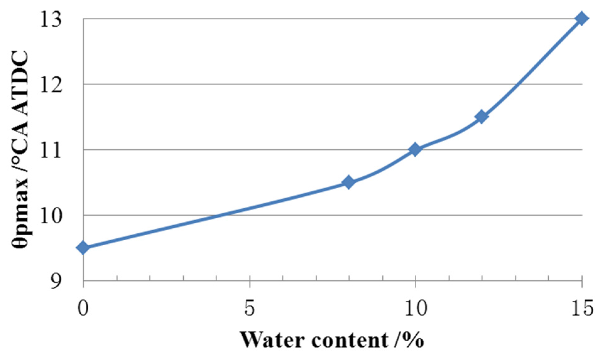
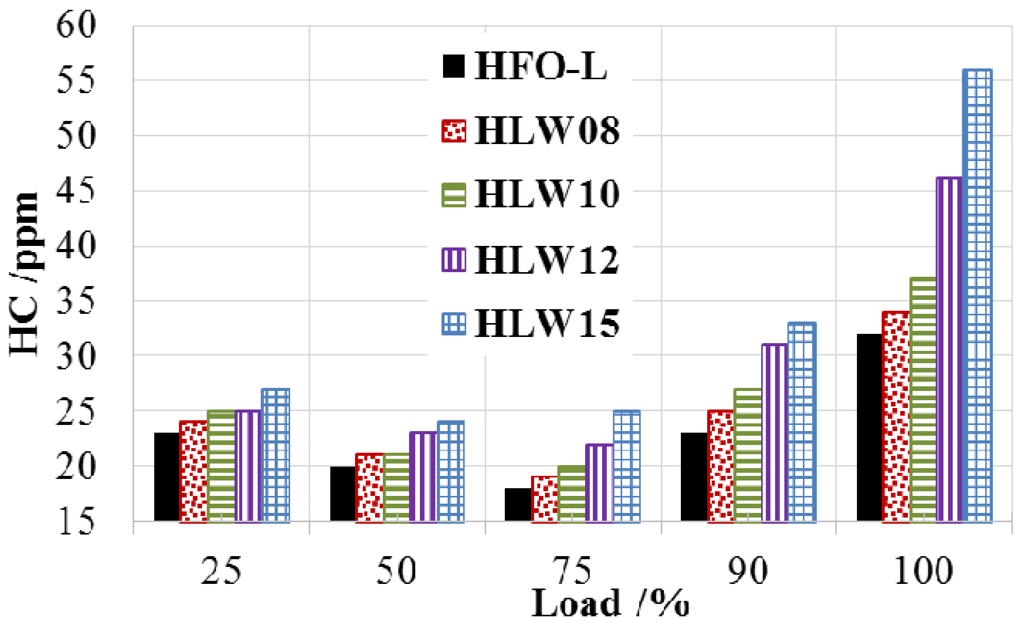
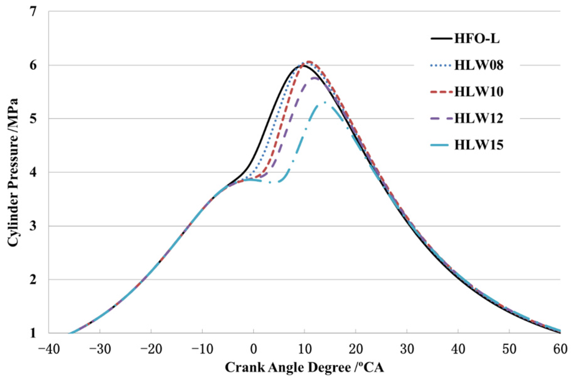
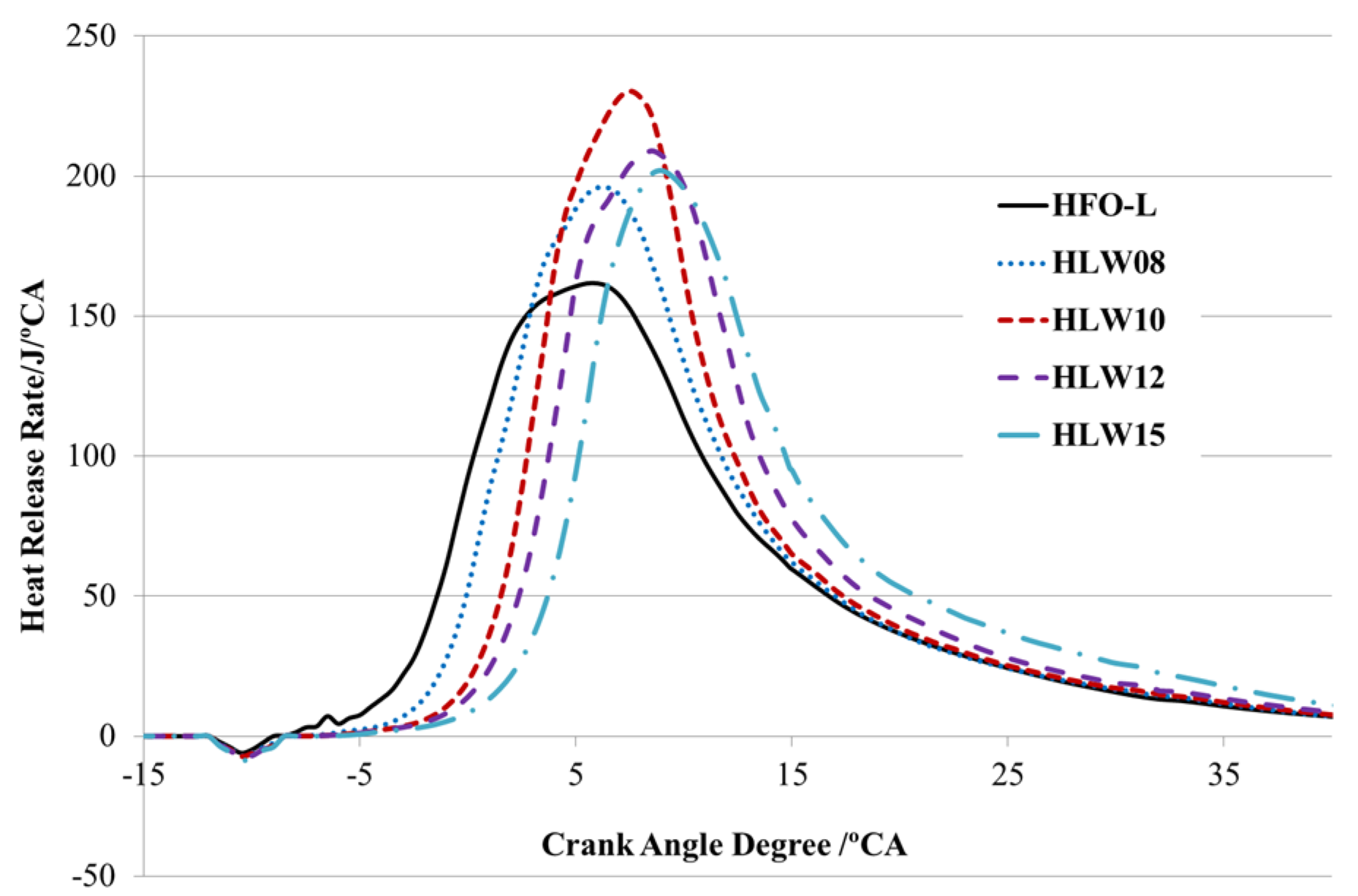
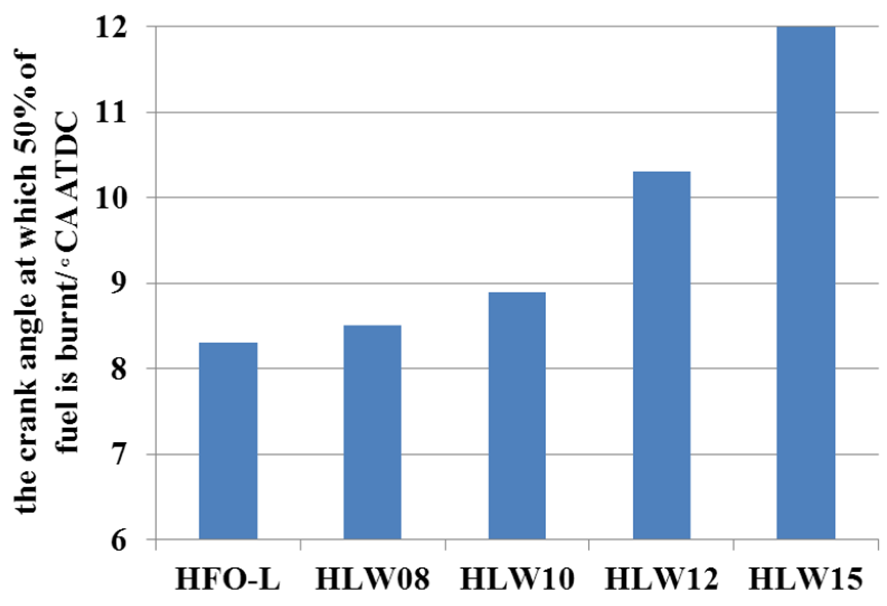
3.2. Effect of the Blend of Heavy Fuel Oil and Light Diesel Fuel Water-Emulsification on Engine Performance

With the modified nozzle and combustion chamber, the performance of the engine fueled with the five fuel blends was tested. Figure 9 is the comparison of cylinder pressure curves under 100% load conditions. After adding water to the HFO-L blend, the start of the combustion is retarded, and time of maximum cylinder pressure (θpmax) is delayed. The higher the water content is, the longer the ignition delay is and the latter is θpmax. This tendency agrees with the results of references [13,15,17].
Figure 9. The comparison of cylinder pressure curves of the cases of fueling with five fuel blends.
Energies 08 12387 g009
The increase of ignition delay is basically due to the lower gas temperature caused by water evaporation. The prolongation of ignition has a great influence on the engine’s performance. Longer ignition delay leads to a shifting of θpmax and a change of the value of pmax. As shown in Figure 9, when the water content is not higher than 10%, the values of pmax are higher than that of HFO-L. But for the cases of water content higher than 10%, pmax decreases as water content increases further.
Figure 10 is the comparison of heat release rate curves. The figure shows that all of the water emulsified fuels have higher heat release rate curve peaks, and HLW10 has the highest peak. The higher peak values of the water emulsified fuels are basically caused by the micro-explosion effect, which increases the fuel-air mixing rate and thus accelerates the combustion rate. Figure 11 presents the time at which 50% of the fuel is burnt. It is shown that with the increase of water content in the emulsified fuels, the time is delayed. For the water contents of 8% and 10%, the times are respectively 0.2 degree and 0.6 degree later than that of the HFO-L, but for the water contents of 12% and 15%, the times are individually 2 degree and 3.7 degree later than that of the HFO-L. The changes of the time will also affect the specific fuel consumption of the engine.
Figure 10. Comparison of the heat release rate curves of the cases fueled with four fuel blends.
Energies 08 12387 g010
Figure 11. The crank angle at which 50% of the fuel is burnt.
Energies 08 12387 g011
Figure 12 shows a comparison of the specific fuel consumption. Although under most of the load conditions, HLW fuels presents lower BSFC than HFO-L, the BSFC decrease trend does not match the increase of water content in the four HLW fuels. Among the four HLW fuels, HLW10 appears to have the lowest equivalent BSFC under all load conditions. At 100% load, the BSFC of HLW10 is 221 g/kW·h, being 9.5 g/kW·h (4%) lower than that of HFO-L, but HLW12 and HLW15 have higher BSFC than HLW08 and HLW10. At 90% and 100% load conditions, HLW15 has a higher BSFC than HFO-L.
Figure 12. Comparison of brake specific fuel consumption (BSFC).
Energies 08 12387 g012
In this research, the variation of BSFC according to water content in fuel is different from that reported in other references. Actually, the effect of water emulsification on an engine’s thermal efficiency is a controversial topic. Some references mention that with water emulsification, the BSFC decreases [4,5,10]. In [5], up to 20% water content, BSFC decreases as the water percentage in the emulsion increases. Some other references declare that water emulsified fuel has higher BSFC, and higher water content leads to even higher BSFC [7,9,11,12].
This discrepancy is caused by a number of reasons, such as different situations of the engine combustion system, injection system, fuel injection timing, fuel emulsification situation, engine operating conditions, etc. Water emulsification of fuel has two opposite influences on engine thermal efficiency: on the one hand, it worsens the engine efficiency due to the higher energy needed for water evaporation and longer ignition delay leading to later θpmax; on the other hand, the mixing rate and combustion rate can be increased due to the micro-explosion effect. The change of the thermal efficiency is the result of the tradeoff between the two effects. In this research, the positive effect of micro-explosions on increasing the burning rate is utmost when the water content is 10%. With a water content higher than 10%, the negative effect of more water evaporation-related heat absorption, and later combustion phase resulting in later θpmax overwhelms the increase in burning rate gain, then the engine efficiency decreases and accordingly its BSFC increases. When the water contents are 12% and 15%, the values of θpmax are too late. This is one of the reasons for the decrease of thermal efficiency. Figure 13 and Figure 14 show the variation tendency of θpmax and thermal efficiency as the water content changes from 0 to 15%.
Figure 13. Variation tendency of θpmax according to water content in fuel.
Energies 08 12387 g013
Figure 14. Variation tendency of brake thermal efficiency according to water content in fuel.
Energies 08 12387 g014
As for harmful emissions, water emulsification has an apparent effect on the reduction of NOx and soot emissions. The soot emissions were measured with a FBY-1 filter paper smoke meter (Fofen Analytical Instrument Ltd., Foshan, China), whose accuracy range is ±3% of full scale. Figure 15 and Figure 16 show the variation trends of the two emissions according to the water content changes. As water content increases, both NOx and soot emissions decrease under all of the load conditions. The reduction of NOx emissions is clearly caused by the decrease of local flame temperature that results from water evaporation in the cylinder [20]. The higher the water content is, the more reduction of NOx emissions. In addition, because water droplets improve the intensity of secondary atomization and provide a finer spray flow [22], fuel-air mixing was improved and soot emissions were reduced.
Figure 15. Variation tendency of NOx emissions.
Energies 08 12387 g015
Figure 16. Variation tendency of soot. BSU—Bosch smoke unit.
Energies 08 12387 g016
Figure 17 and Figure 18 are the variation trends of HC emissions and CO emissions. It is shown in Figure 17 that with the increase of water content, HC emissions are increased. The longer penetration of emulsified fuel [17] explains this tendency. Because of the longer penetration, more fuel impinges on the chamber wall and this causes more flame quenching effects, leading to higher HC emissions. As for CO emissions, under most of the load conditions, emulsified fuels have higher CO than HFO-L, but with the exception of HLW08 and HLW10 at 90% and 100% load conditions. Under these load conditions, both emulsified fuels presented slightly lower CO than HFO-L. Under low load conditions, the lower combustion temperature of HLW leads to higher CO. For the cases of HLW08 and HLW10 under 90% and 100% load conditions, the micro-explosion process leading to finer atomization causes a faster burning rate and this results in lower CO values.
Figure 17. Variation tendency of HC.
Energies 08 12387 g017
Figure 18. Variation tendency of CO.
Energies 08 12387 g018
In summary, comparing the five fuels, HLW10 presents the best comprehensive performance with the best fuel economy, third lowest NOx and soot emissions. HLW15 has the lowest NOx and soot emissions, but its BSFC is higher than HFO-L.

3.3. Summary of the Engine Performance Improvement Strategy

The aim of this research was to substitute light diesel with HFO with the premise of maintaining the power performance, reliability, and acceptable slightly increased BSFC. Meanwhile, emission characteristics are also considered. By modifying the nozzle and combustion chamber, HFO-L was usable in the engine, and the engine reliability was ensured. However BSFC and soot emissions were still high. After using HLW10, BSFC and soot emissions were reduced, approaching those of the baseline engine fueled with light diesel standard; and NOx emissions were lower than that of the baseline. Figure 19 presents a comparison of engine performance between the four strategies.
Figure 19. Engine performance improvement strategy.
Energies 08 12387 g019

4. Conclusions

(1)
Using HFO and light diesel blend (HFO-L) in a high-speed diesel is a feasible way to reduce the running costs of the engine. In order to ensure the engine’s reliability and maintain its power performance and fuel economy, modifications to the combustion system and fuel injection system are necessary. This research proved the validation of the modifications of the combustion chamber and fuel injector of the engine to adapt HFO-L.
(2)
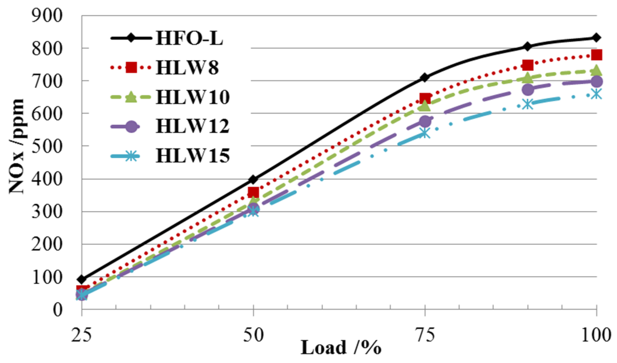
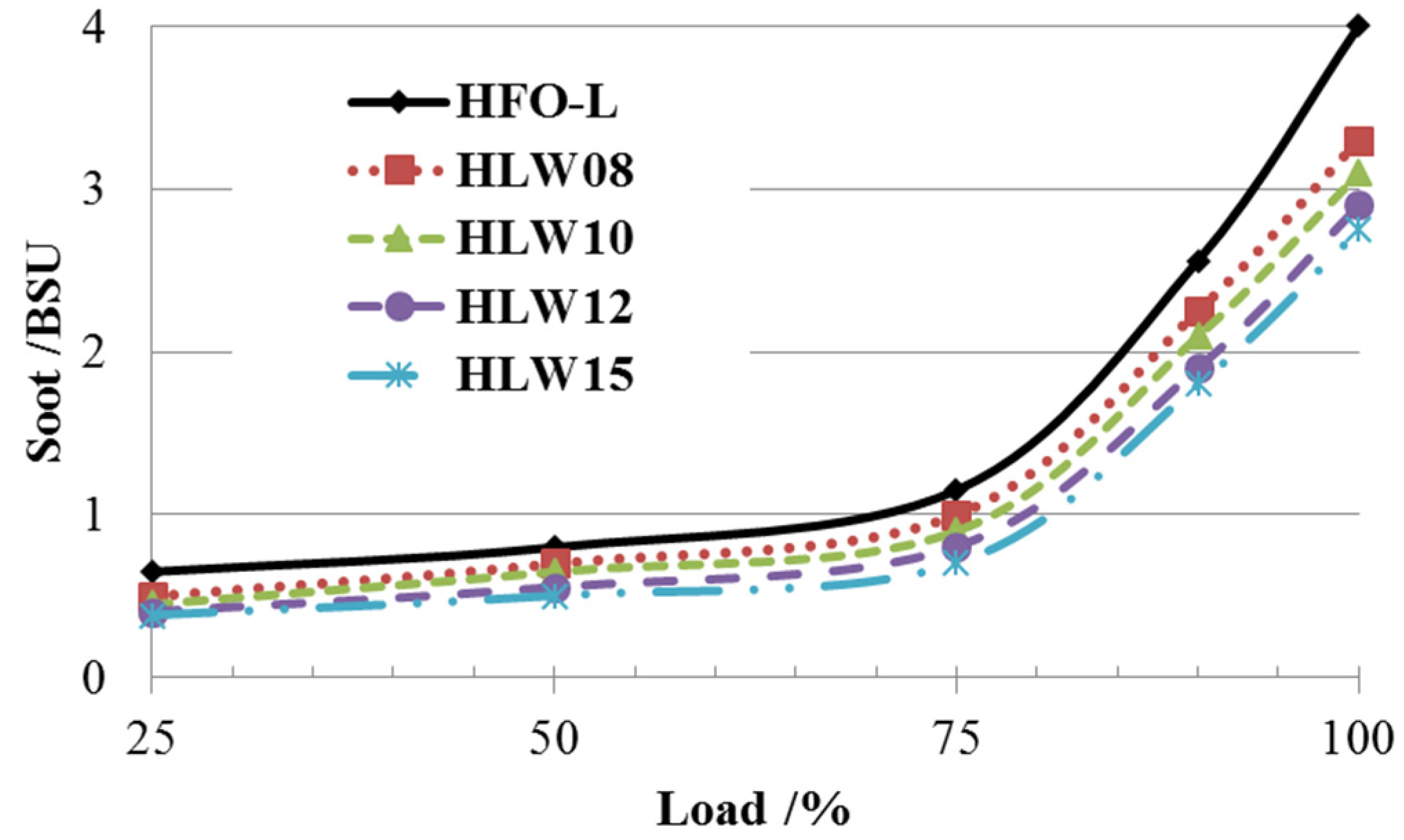
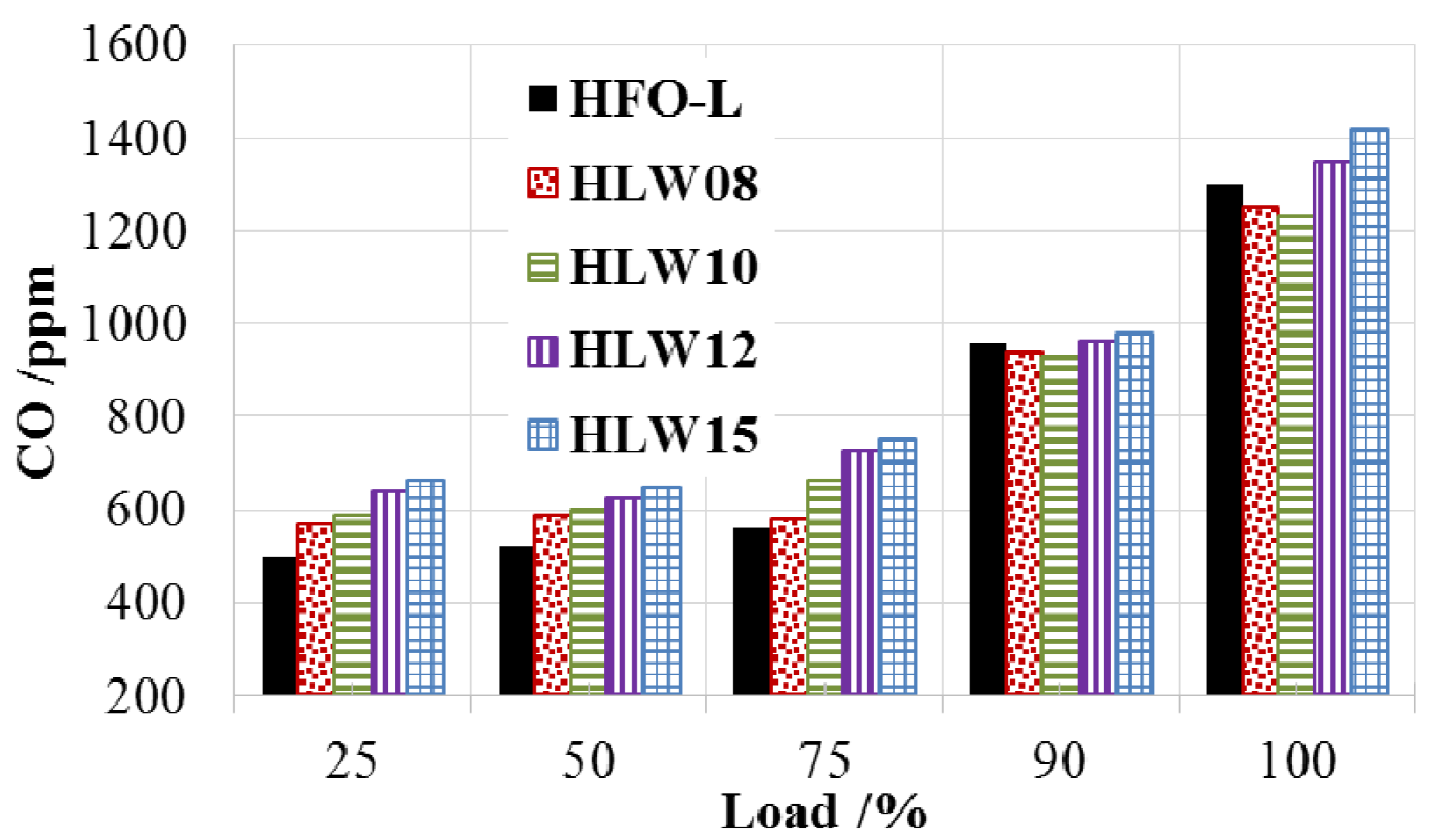
Use of HFO must result in higher soot emission compared with the use of light diesel. This problem can be solved by using emulsified fuel. When using water emulsified HFO-L, the soot emissions are greatly reduced compared with HFO-L. Meanwhile, water emulsification leads to lower NOx emissions. The positive change of soot and NOx emissions is very attractive for engine users.
(3)
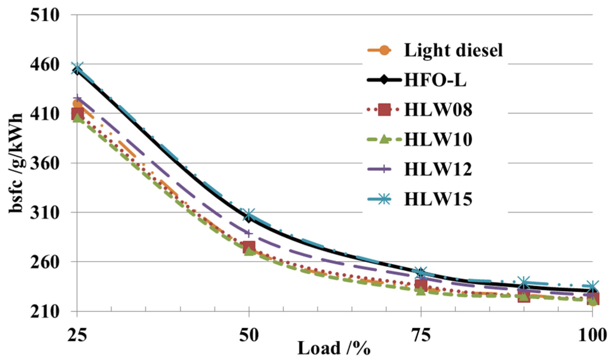
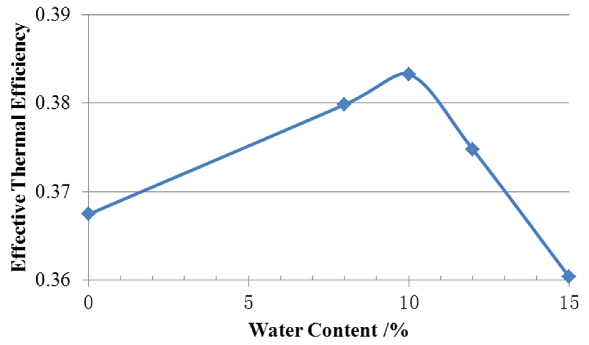
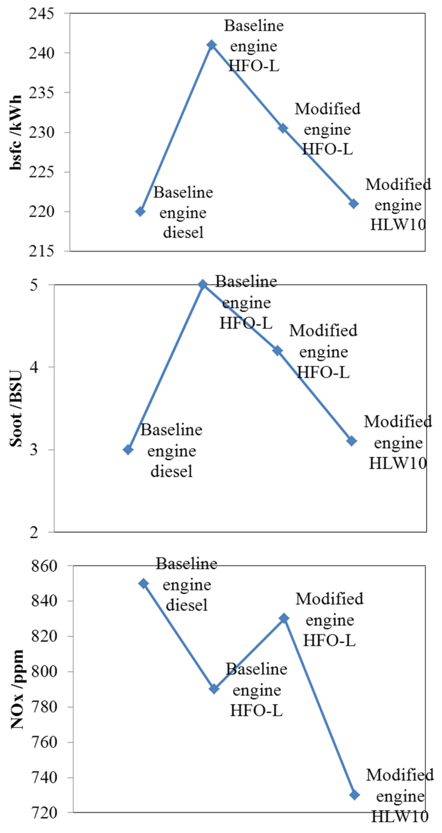
Moderate water emulsified fuel also leads to lower BSFC compared with the fuel without water emulsification. There is an optimal value of water content for emulsified fuel. In this research 10% of water emulsification presented the best performance.
(4)
With the combination of the modified injection system and combustion system and using water emulsified HFO (HLW10), the engine presents much better fuel economy, lower NOx emissions, and maintains the same power performance as the prototype engine which uses light diesel.
(5)
Later research will include the measurement of the fuel injection characteristics and auto-ignition characteristics of emulsified HFO-L, which should be very helpful for understanding the energy saving mechanism and harmful emission reduction.

Acknowledgments

This research was financially supported by National Natural Science Foundations of China 51479028 and 51079026.

Author Contributions

All the authors have co-operated for the preparation of the work. Liyan Feng and Bin Tang have designed the research. A part of experiment and analysis were carried out by Baoguo Du, Jiangping Tian and Wuqiang Long.

Conflicts of Interest

The authors declare no conflict of interest.

References

  1. Feng, L.Y.; Du, B.G.; Li, J.X.; Liu, X. Experimental Research and Numerical Simulation on Performance of Heavy Fuel Oil Medium Speed Diesel Engine. Chin. Intern. Combust. Engine Eng. 2012, 33, 75–81. (In Chinese) [Google Scholar]
  2. Air Emissions Legislation Review for Internal Combustion Engines; Wärtsilä Corporation: Vaasa, Finland, 2003.
  3. Sarvia, A.; Kilpinenb, P.; Zevenhovena, R. Emissions from large-scale medium-speed diesel engines: 3. Influence of direct water injection and common rail. Fuel Process. Technol. 2009, 90, 222–231. [Google Scholar] [CrossRef]
  4. Xu, F.; Wu, W.B.; Zhang, D.L.; Du, B.G.; Ma, F.J. The Application of Emulsified Fuel to 1135 Diesel Engine. Chin. Intern. Combust. Engine Eng. 2002, 6, 55–58. (In Chinese) [Google Scholar]
  5. Abu-Zaid, M. Performance of single cylinder, direct injection Diesel engine using water fuel emulsions. Energy Convers. Manag. 2004, 45, 697–705. [Google Scholar] [CrossRef]
  6. Armasa, O.; Ballesterosa, R.; Martosb, F.J.; Agudelo, J.R. Characterization of light duty Diesel engine pollutant emissions using water-emulsified fuel. Fuel 2005, 84, 1011–1018. [Google Scholar] [CrossRef]
  7. Nadeem, M.; Rangkuti, C.; Anuar, K.; Haq, M.R.U.; Tan, I.B.; Shah, S.S. Diesel engine performance and emission evaluation using emulsified fuels stabilized by conventional and gemini surfactants. Fuel 2006, 85, 2111–2119. [Google Scholar] [CrossRef]
  8. Alahmer, A.; Yamin, J.; Sakhrieh, A.; Hamdan, M.A. Engine performance using emulsified diesel fuel. Energy Convers. Manag. 2010, 51, 1708–1713. [Google Scholar] [CrossRef]
  9. Alahmer, A. Influence of using emulsified diesel fuel on the performance and pollutants emitted from diesel engine. Energy Convers. Manag. 2013, 73, 361–369. [Google Scholar] [CrossRef]
  10. Ithnin, A.M.; Ahmad, M.A.; Bakar, M.A.A.; Rajoob, S.; Yahya, W.J. Combustion performance and emission analysis of diesel engine fuelled with water-in-diesel emulsion fuel made from low-grade diesel fuel. Energy Convers. Manag. 2015, 90, 375–382. [Google Scholar] [CrossRef]
  11. Raheman, H.; Kumari, S. Combustion characteristics and emissions of a compression ignition engine using emulsified jatropha biodiesel blend. Biosyst. Eng. 2014, 123, 29–39. [Google Scholar] [CrossRef]
  12. Koc, A.B.; Abdullah, M. Performance and NOx emissions of a diesel engine fueled with biodiesel-diesel-water nanoemulsions. Fuel Process. Technol. 2013, 109, 70–77. [Google Scholar] [CrossRef]
  13. Kadota, T.; Yamasaki, H. Recent advances in the combustion of water fuel emulsion. Prog. Energy Combust. Sci. 2002, 28, 385–404. [Google Scholar] [CrossRef]
  14. Debnath, B.K.; Saha, U.K.; Sahoo, N. A comprehensive review on the application of emulsions as an alternative fuel for diesel engines. Renew. Sustain. Energy Rev. 2015, 42, 196–211. [Google Scholar] [CrossRef]
  15. Yoshimoto, Y. Performance of DI Diesel Engines Fueled by Water Emulsions with Equal Proportions of Gas Oil-Rapeseed Oil Blends and the Characteristics of the Combustion of Single Droplets. SAE Paper 2006-01-3364. In Proceedings of the Powertrain & Fluid Systems Conference and Exhibition, Toronto, ON, Canada, 2006.
  16. Attia, A.M.A.; Kulchitskiy, A.R. Influence of the structure of water-in-fuel emulsion on diesel engine performance. Fuel 2014, 116, 703–708. [Google Scholar] [CrossRef]
  17. Huo, M.; Lin, S.; Liu, H.; Lee, C.F. Study on the spray and combustion characteristics of water-emulsified diesel. Fuel 2014, 123, 218–229. [Google Scholar] [CrossRef]
  18. Tarlet, D.; Bellettre, J.; Tazerout, M.; Rahmouni, C. Prediction of micro-explosion delay of emulsified fuel droplets. Int. J. Therm. Sci. 2009, 48, 449–460. [Google Scholar] [CrossRef]
  19. Ocampo-barrera, R.; Villasenor, R.; Diego-marin, A. An experimental study of the effect of water content on combustion of heavy fuel oil/water emulsion droplets. Combust. Flame 2001, 126, 1845–1855. [Google Scholar] [CrossRef]
  20. Ballester, J.M.; Fueyo, N.; Dopazo, C. Combustion characteristics of heavy oil-water emulsions. Fuel 1996, 75, 695–705. [Google Scholar] [CrossRef]
  21. ISCapture User Guide. Available online: http://www.tucsen.com/Home/Product/download/dataid/3/id/19.html (accessed on 16 January 2015).
  22. Watanabe, H.; Okazaki, K. Visualization of secondary atomization in emulsified-fuel spray flow by shadow imaging. Proc. Combust. Inst. 2013, 34, 1651–1658. [Google Scholar] [CrossRef]

