Article

Development of a Digital and Battery-Free Smart Flowmeter

Mechanical Engineering Department, Kun Shan University, 195 Kun Da Road, Tainan City 71003, Taiwan
*
Author to whom correspondence should be addressed.
Energies 2014, 7(6), 3695-3709; https://doi.org/10.3390/en7063695
Submission received: 14 March 2014 / Revised: 14 May 2014 / Accepted: 26 May 2014 / Published: 16 June 2014

Abstract

:
To effectively manage and save energy and natural resources, the measurement and monitoring of gas/fluid flows play extremely important roles. The objective of this study was to incorporate an efficient power generation and a power management system for a commercial water flow meter thus eliminating the usage of batteries. Three major technologies have made this possible: a low power consumption metering unit, a cog-resistance-free generator with high efficiency; and an effective methodology to extract/store energy. In this system, a new attempt and simple approach was developed to successfully extract a portion of the kinetic energy from the fluid/air, store it in a capacitor and used it efficiently. The resistance to the flow was negligible because of the very low power consumption as well as the application of the coreless generator technology. Feasibility was demonstrated through repeated experiments: for air flowing in an 11 mm diameter pipe, 18 s of energy harvesting at 10 revolution-per-second (RPS) turbine speeds generated enough power for the flowmeter to operate for 720 s with a flowrate of 20 RPS, without battery or any external power. The pipeline monitoring in remote areas such as deep sea oil drilling; geothermal power plants and even nuclear power plants could benefit greatly from this self-power metering system design.

Graphical Abstract

1. Introduction

To effectively manage and save energy and natural resources, the measurement and monitoring of gas/fluid flow play extremely important roles. For example, the U.S. domestic market for smart gas meters is expected to increase worldwide contradictory from 22 million in 2012 to 33 million in 2020, at an annual growth rate (CAGR) of 5.5% [1]. The demand for smart water meters is also continuously increasing. Such demand is generating a great impact on the smart metering system supply. The usage of turbine flow meters for industry and domestic purposes has reached 46.6% [2].
For gas flowmeters, pressure and temperature need to be measured to obtain an accurate reading. The energy used by the temperature and pressure sensor need to be taken in consideration before designing an appropriate generator. In the case of water flowmeters temperature and pressure do not affect the volumetric water measurement significantly, so a Woltman design with a few modifications would suit the proposed system [3].
Water metering is a fundamental practice offering improved public health protection, reduced pressure on water natural resources, and increased quality of distribution and therefore public perception of water suppliers [4]. Knowing how much water its being lost or distributed properly enables water suppliers to manage the water distribution network (WDN) efficiently and effectively. Therefore, many new water distribution algorithms are being developed and improved including NSGA-II [5] and the differential evolution [6] to optimize the WDN. However, manual meter reading is still a common practice to collect data in many WDN. With the increases of technological instrumentation, the use of energy increases as well. For water meters in an AMR network, the flow rate information is to be sent to a central station, in most cases wirelessly based on ZigBee communication technology [7].
The importance of having a smart metering system was clearly identified by Stewart: “Reducing the amount of water lost through leaks has further implication for both energy consumption and treatment costs” [8], referring to the use of smart meters to reduce water losses. Currently, very little has been done to create autonomous smart flow meters [9] that can provide such vital information.
Smart metering for gas and water systems depends mainly on the real time data the system could provide. This represents a real challenge since usually there is little or no easy access to the underground pipeline network [10]. The flow meters, sensors and transceivers are not autonomous either, meaning they depend on external power supplies to operate.
This paper demonstrates that a commercial digital flowmeter, capable of detecting leakages and backward flow can operate even at a very low flow rate without a battery or any external power. Moreover, design considerations for gas and water flowmeters as well as further improvements of wireless data transmission are also discussed.

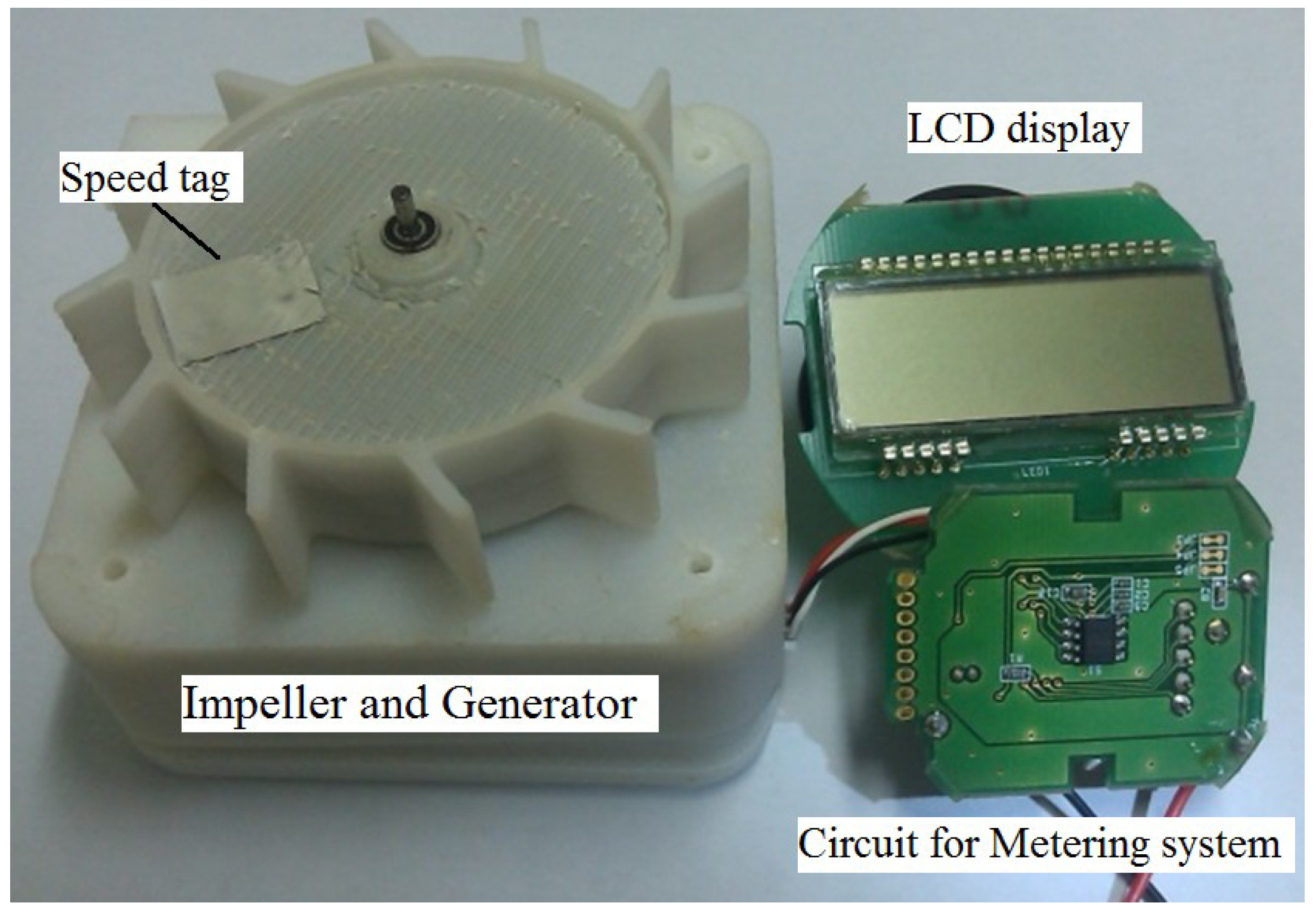
2. Design and Construction of a Smart Flow Meter

For a new generation of Digital Battery Free Smart Flowmeters, there are three major technologies that made it possible: an ultra-low-power-metering-system; a cog-resistance-free generator with high efficiency; and an effective methodology to extract/store its energy.

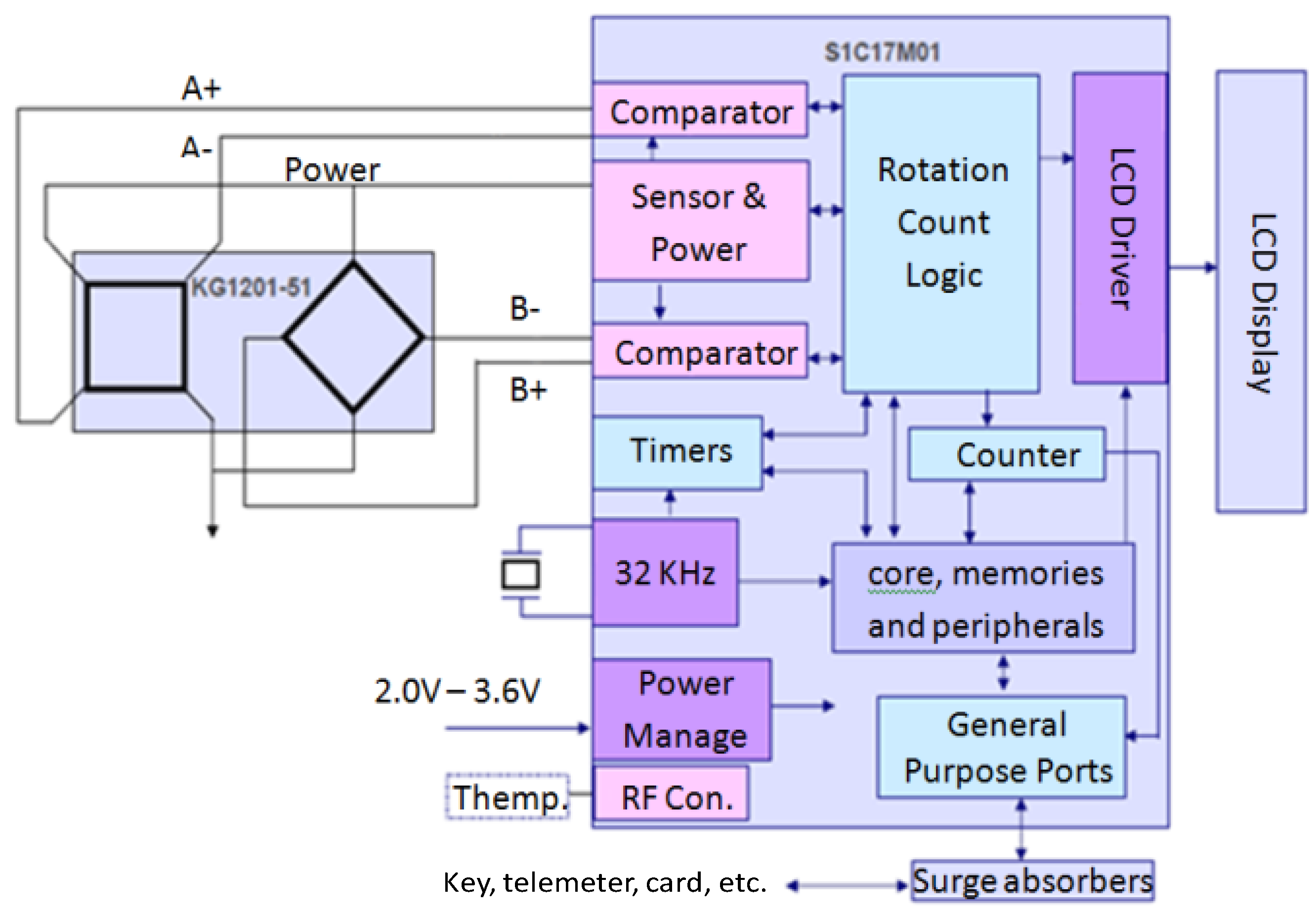
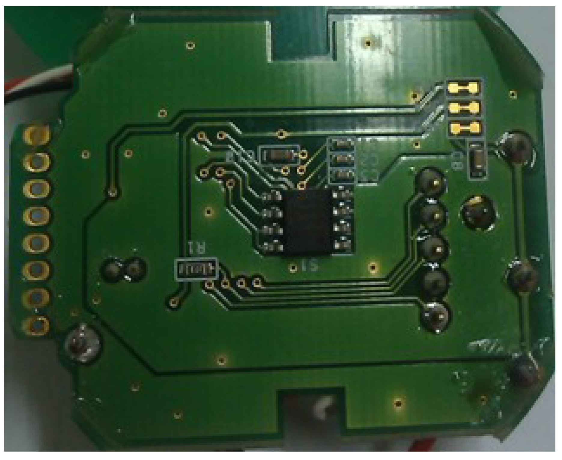
2.1. Ultra Low Power Metering System

In this study the Micro-Controller-Unit (MCU) (S1C17M01) in combination with an Anisotropic-Magnet-Resistance (AMR) sensor (KG1201-51) was utilized, because of its very high power efficiency. The S1C17M01 is a 16-bits MCU that features high-speed, low-power operations, compact dimensions, wide address space, main command single-clock execution, and gate-saving design [11]. The special measuring functions provided by the system are: integrated and instantaneous flow according to impeller count, overflow detection, reverse flow detection, water leak detection, non-use detection, low battery voltage detection and pulse output for telemetering devices. Moreover, the testing board also includes an Anisotropic-Magnet-Resistance (AMR) sensor to detect the rotational speed of the impeller. The AMR sensor is a double full-bridge type, double phase output with a difference of 90 degrees. The sensor is connected directly to the comparators of the microcontrollers so that to reduce power losses, as shown on Figure 1 and Figure 2. The real energy consumption data is presented in the Results and Discussion section of this paper.
Figure 1. Ultralow power metering system designed by EPSON® Corporation.
Energies 07 03695 g001
Figure 2. Block diagram for the metering system.
Energies 07 03695 g002

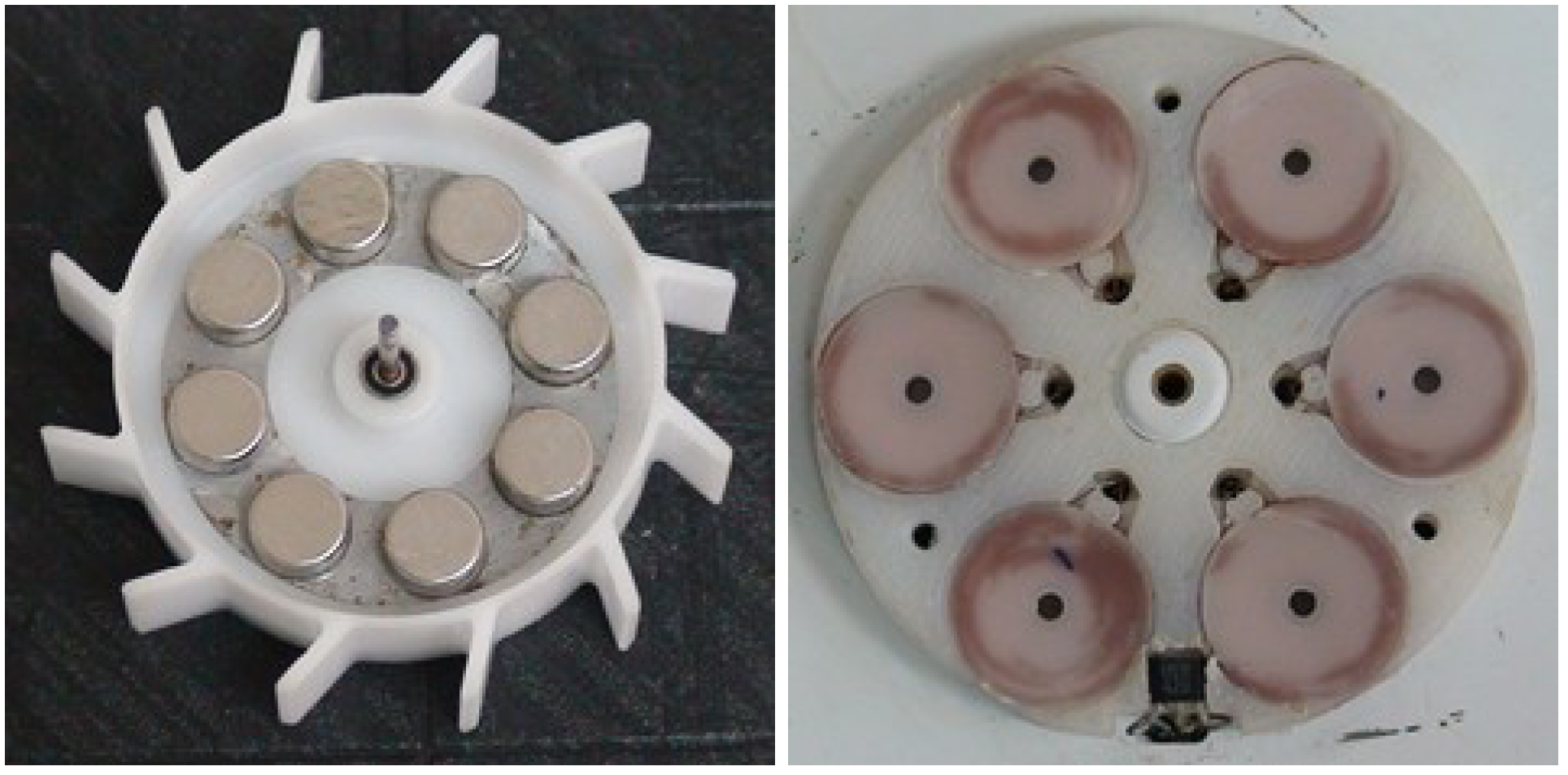
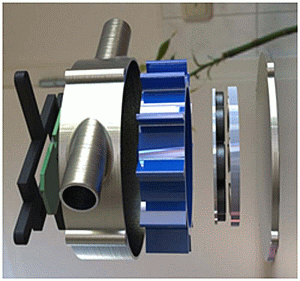
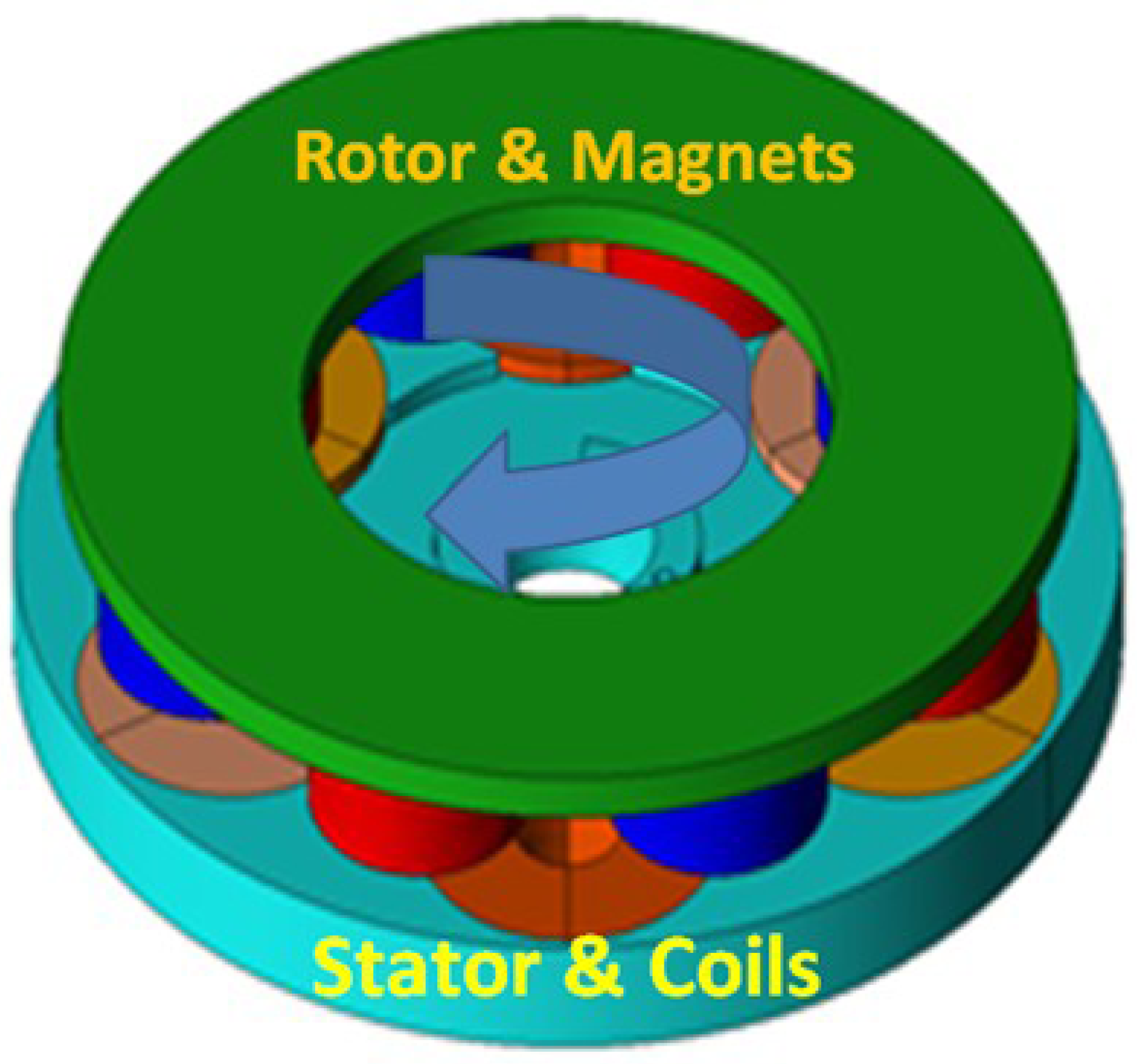
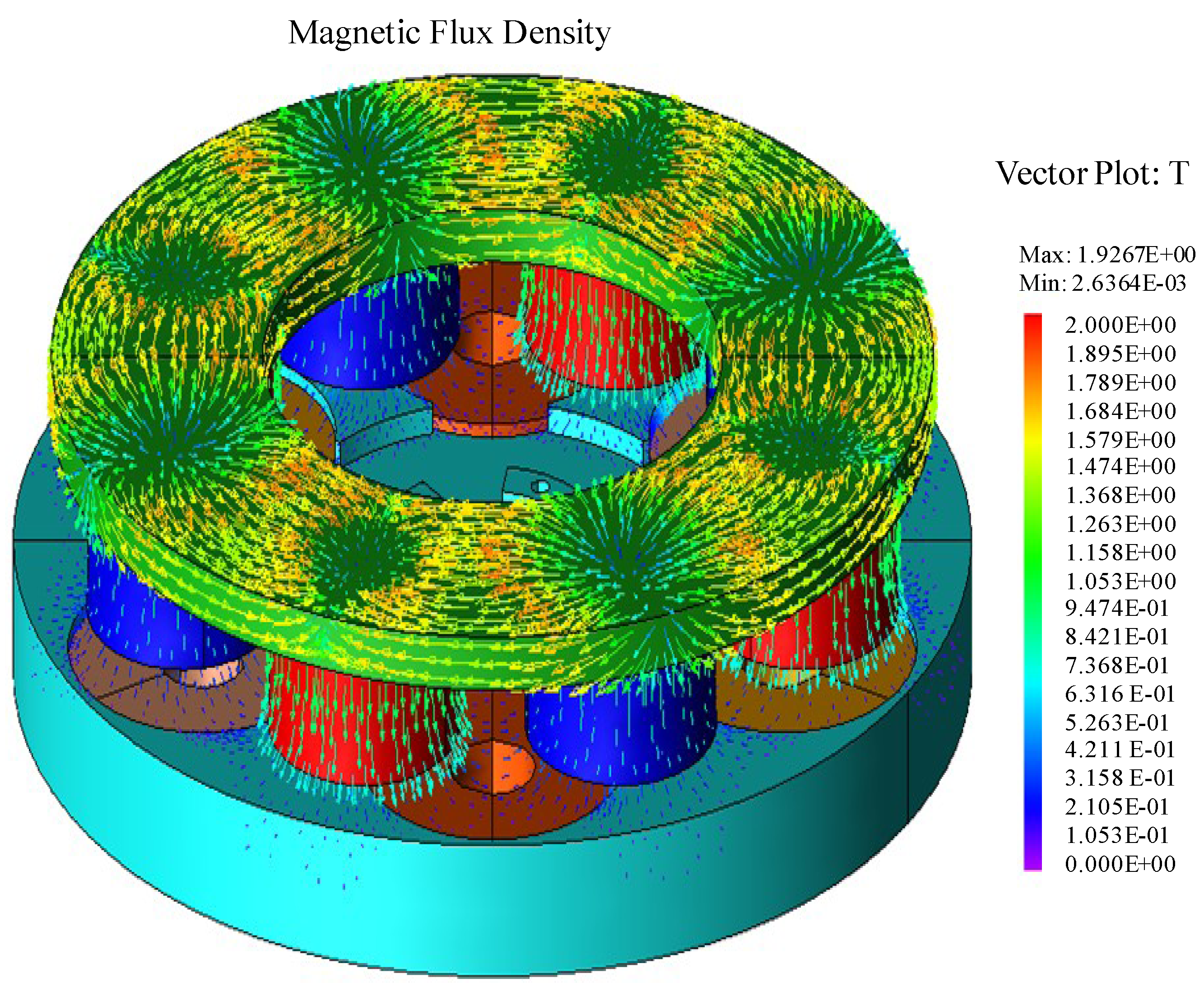
2.2. Cog-Resistance-Free and High Efficiency Generator

The power consumed by the whole system was provided entirely by a high efficient and cogging-resistance-free generator to eliminate the need for an external power source. An Axial-Flux-Permanent-Magnet Generator (AFPM) is characterized by a short axial length and a high number of poles to increase the induced power [12,13]. The AFPM had also been regarded as a high-efficiency machine for distributed power generation systems [14,15,16].
In this study, a single-sided, 6-slot 8-pole, coreless axial-flux permanent magnet (AFPM) generator with a rating of 1.0 W shaft power at 1200 RPM was developed for the proposed device. The structure of the AFPM generator is shown in Figure 3. The coreless AFPM generator is composed of a steel rotor disc and a non-magnetic non-conducting stator disc. The rotor carried eight NdFeB permanent magnets arranged circumferentially around the rotor in a N-S-N-S arrangement, while the stator is made from PEEK engineering plastic carrying coils to eliminate the cogging torque and reduce the iron loss. Then, the pneumatic turbine (impeller) is integrated with the rotor disc of the AFPM generator. The special designed generator is cost effective, reliable and simple to manufacture.
Figure 3. Structure of the coreless AFPM generator.
Energies 07 03695 g003
In a coreless AFPM generator, the permanent magnet (PM) can replace the field winding, so the copper losses are eliminated. Furthermore, the stator is made from a non-magnetic non-conducting material with lightweight structure, such as PEEK engineering plastics. Therefore the iron losses are eliminated and the cog-resistance is reduced to the minimum. With this design, coreless AFPM generators have the advantages of simpler construction, lower weight and size for the same performance, reduced losses, and higher efficiency [17].
The AFPM generator or power generation unit schematic is shown in Figure 4. From the picture, it is clear that the power is delivered from three phases. The prototype of the final design is shown in Figure 5 and major parameters of this AFPM generator design are listed in Table 1.
Figure 4. Axial-Flux-Permanent-Magnet (AFPM) Generator Schematic.
Energies 07 03695 g004
Figure 5. Prototype of the Rotor and the stator.
Energies 07 03695 g005
Table 1. Geometric parameters of axial-flux-permanent-magnet generator.
Phase3(Y)Air-Gap (mm)0.5
Pole8Stator diam.50
Slot6Rotor diam.46
Rotor YokeS45CCoil (turns)900
StatorPEEKSpeed (RPM)300–1500
MagnetNEOMAX-35
The above mentioned turbine was used to convert the kinetic energy of the flow to electric energy. The kinetic energy depends on the mass of flow M (kg) and the velocity v expressed as [18]:
Energies 07 03695 i001
M = Vρ; V = Avt
where V stands for volume(m3); ρ for density ( Energies 07 03695 i002
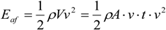
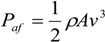
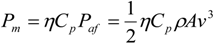
); t for time [s] and A for area (m2). Therefore:
Energies 07 03695 i003
In order to convert the kinetic energy in mechanical power at a specific time interval, the following expression was used:
Energies 07 03695 i004
The mechanical power from a pneumatic turbine can be expressed as:
Energies 07 03695 i005
where η presents the mechanical efficiency; Cp stands for the coefficient of performance of the turbine including the generator. This Cp variable is required since not all the kinetic power of the flow can be converted into electric power. The Cp value represents a 20% to 50% of the total mechanical power.

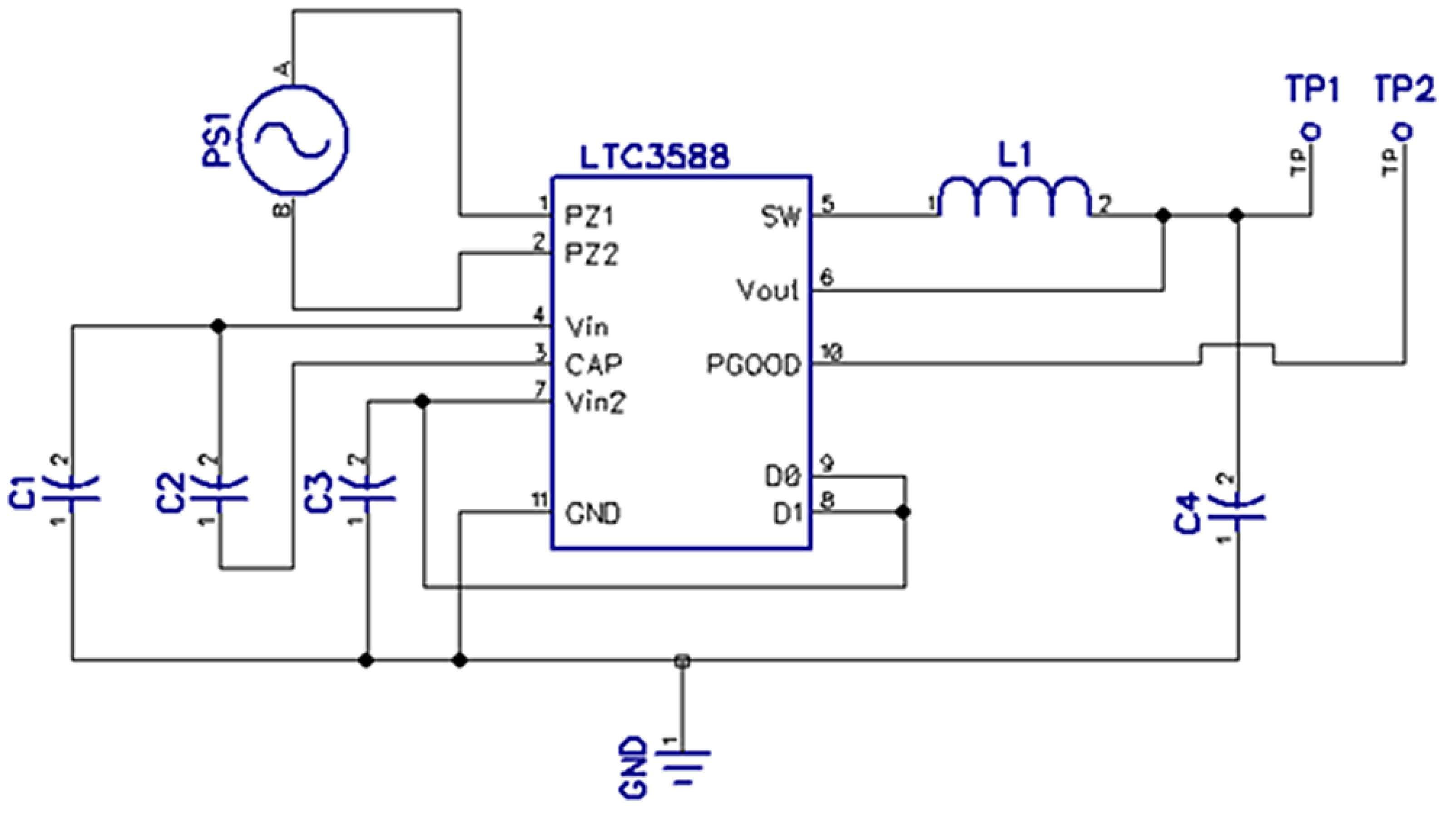
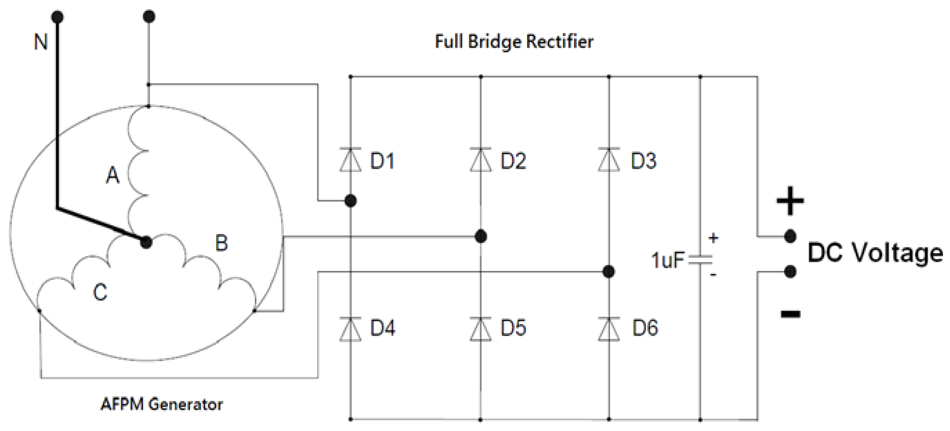
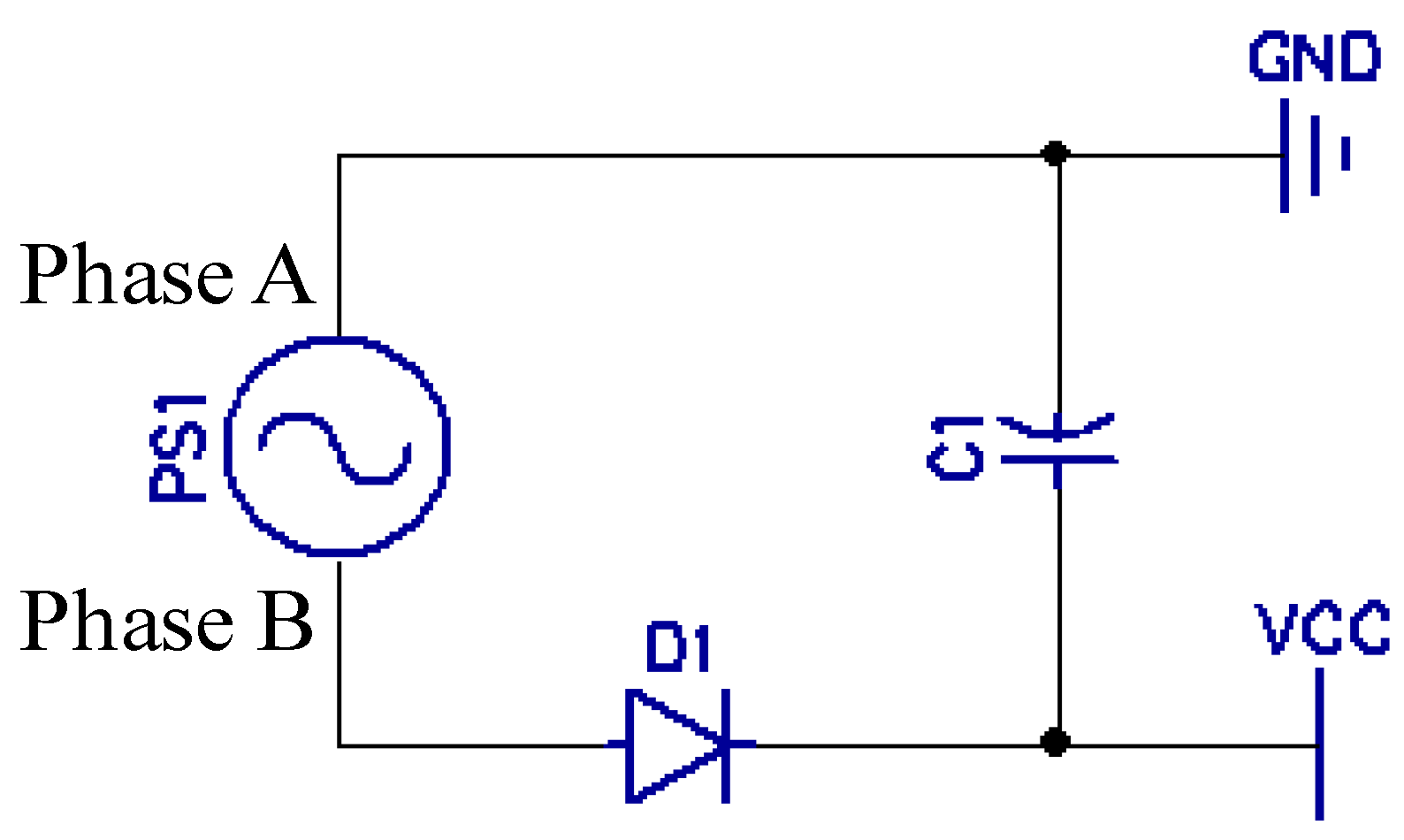
2.3. Energy Harvesting Technique

The feasibility for energy harvesting depends mainly on four factors: the typical power consumption of the device; the usage pattern; the device size; and the motion to which the device is subjected [18]. Energy harvesters produces power from the local environment, eliminating batteries in wireless sensors [19]. All the characteristics of a flow meter and its working environment are favorable for energy harvesting. In the case of this study the kinetic energy of the flow was converted in electric power. Once the mechanical energy was converted into electrical energy the next step was to manage that energy in an efficient way. Three approaches were studied:
The first approach was using an energy harvesting IC (integrated circuit). The LTC3588 which integrates a low-loss full-wave bridge rectifier with a high efficiency buck converter to form a complete energy harvesting solution was used for this purpose [20].
The modus of operation of the LTC3588 is as follows (refer to Figure 6): PZ1 and PZ2 receive an AC signal, this signal then is rectified by a low loss internal bridge rectifier with a synchronous step-down DC/DC converter. The IC has an undervoltage lockout mode with a wide hysteresis window that draws less than a μA of quiescent current. This UVLO mode allows charges to build up in an input capacitor connected on Vin until charges can effectively be transferred to the output. The buck regulator uses a hysteresis voltage algorithm to control the output via internal feedback from the Vout sense pin. It charges the output capacitor through an inductor to a value slightly higher than the regulation point by ramping the inductor current up to 250 mA through an internal PMOS switch and then ramping it down to zero current through an internal NMOS switch. This effectively delivers energy to the output capacitor [21].
The circuit used for testing in this study is shown in Figure 6. The values of the different components from left to right are as follows: C1 is 10 mF 25V, C2 is 1 µF, C3 is 4.7 µF, C4 is 4.7 µF, PS1 is AC source of the generator, and L1 is 10 µH. D0 and D1 are connected to Vin2 so that the output voltage, on Vout pin, was regulated to 3.6 V. Figure 6 shows a single phase arrangement for simplicity. However, in the experiment multiple as well as single phases were tested.
The IC was ideal for handling low speed (<15 RPS)—low power (<3.6 mW) but failed to function properly until it burned out with higher speed—higher power. In order to protect the IC from high power the datasheet recommends the installation of two resistors between A and PZ1 as well as B and PZ2 (Figure 7). However, the two resistors create excessive load to the generator. The drawback of the IC and its circuitry was the high load produced which increased the torque in the generator making the meter less ideal for low speed and low density applications.
Figure 6. Energy harvesting IC circuit schematic.
Energies 07 03695 g006
The second approach tested was using an existing circuit [17]. Figure 7 shows the circuit tested. The circuit consists of six diodes that function as a full bridge rectifier converting the power from AC to DC and a 1 µF capacitor.
Figure 7. AFPM Generator schematic.
Energies 07 03695 g007
The drawback was that the force required to rotate the impellers was too high, which would make the system of little use, especially for low flow rates. Obviously the losses came mainly from the six diodes that made the conversion as well as the load.
The final approach succeeded: in order to efficiently store enough power and minimize resistance to the flow, a single diode with 10 mF capacitor was used to extract the energy from a single phase, leaving the other two phases disconnected.
This simple way to extract the energy and store it in a capacitor has two advantages:
(1)
Low torque, only two components and its expandability;
(2)
By using a super capacitor (1 F to 10 F), hours of continuous operation without recharging can be accomplished.
Figure 8 represents the schematic used in this last approach.
Figure 8. Schematic of AC to DC conversion and energy storage for a single phase.
Energies 07 03695 g008
The energy stored in the capacitor can be calculated with the following equation:
Energies 07 03695 i006
where E is the energy stored in mJ; C is the capacitance of the capacitor in mF and V is the voltage of the power supplied.

3. Finite Element Modeling/Simulation

Before finalizing the design and going to the fabrication stage, 3D-Finite Element Method (FEM) electromagnetic simulation, was applied to predict the performance of the AFPM generator. The 3-D FEM model not only can validate the 3-D flux density distribution more accurately, but it can also analyze the analytical sizing equation and predict the machine performance. Figure 9 demonstrates a simulated 3-D air-gap flux density distribution of the proposed AFPM machine to predict the induced EMF of stator windings. Parametric study through FEM results was conducted to optimize the design.
Figure 9. Air-gap flux density using 3-D FEM simulation.
Energies 07 03695 g009
From the FEM simulation, the Induced voltage profiles with load or without load are presented in Figure 10 and Figure 11, for the final generator design.
Figure 10. Induced voltage profile with no-load (600 rpm).
Energies 07 03695 g010
Figure 11. Induced voltage profile with a heavy-load of 100 Ω/phase (600 rpm).
Energies 07 03695 g011

4. Experimental Setup

For a new generation of digital, battery-free and smart flow-meters, the design of a very compact, lightweight and reliable system has been accomplished. The exploded view of the mechanism which is composed of (from left to right): frame, IC circuit with sensor, casing, impeller, rotor with magnets, stator with coils, and the cap is shown in Figure 12.
Figure 12. Design of the mechanism (left to right): frame, IC circuit and sensor, casing, blades, magnets, coils, and cap.
Energies 07 03695 g012
For a liquid metering system, special design with seamless consideration could also be accomplished. The real prototype built to perform all the experiments is shown in Figure 13.
Figure 13. Experimental setup.
Energies 07 03695 g013
The experiment was conducted using a 11 mm internal diameter pipe at flow rates ranging from 0.3 M3/h up to 1.2 M3/h. The flow rate was then converted to RPS. In order to simplify the experiments a stepper motor was used to simulate flowing air. The stepper motor allowed the speed of the impeller to be controller according to the RPS obtained to gather consistent data.

5. Result and Discussion

Experiments were conducted and the corresponding results are expressed as follows:

5.1. The Power Consumption

The total power consumption of the system was obtained by attaching a voltmeter and a current meter to it, as for the sensor, CPU, RTC, and the LCD the power consumption was obtained by disabling them. A stepper motor was used to maintain a constant rotational speed in the impellers.
The power consumption of the entire system was 4.75 μA at 25 RPS and 2.0 μA when idle. During the experiment, it was noticed that the meter continued working normally until the voltage dropped below 1.6 V. Table 2 presents the power consumption of the main components in the system.
Table 2. Power consumption per component.
RPSSensorCPURTCLCDTotal (µA)Volts (V)Total (μW)
50.700.151.20.52.553.38.42
101.100.301.20.53.103.310.23
151.500.451.20.53.653.312.05
201.900.601.20.54.203.313.86
252.300.751.20.54.753.315.68

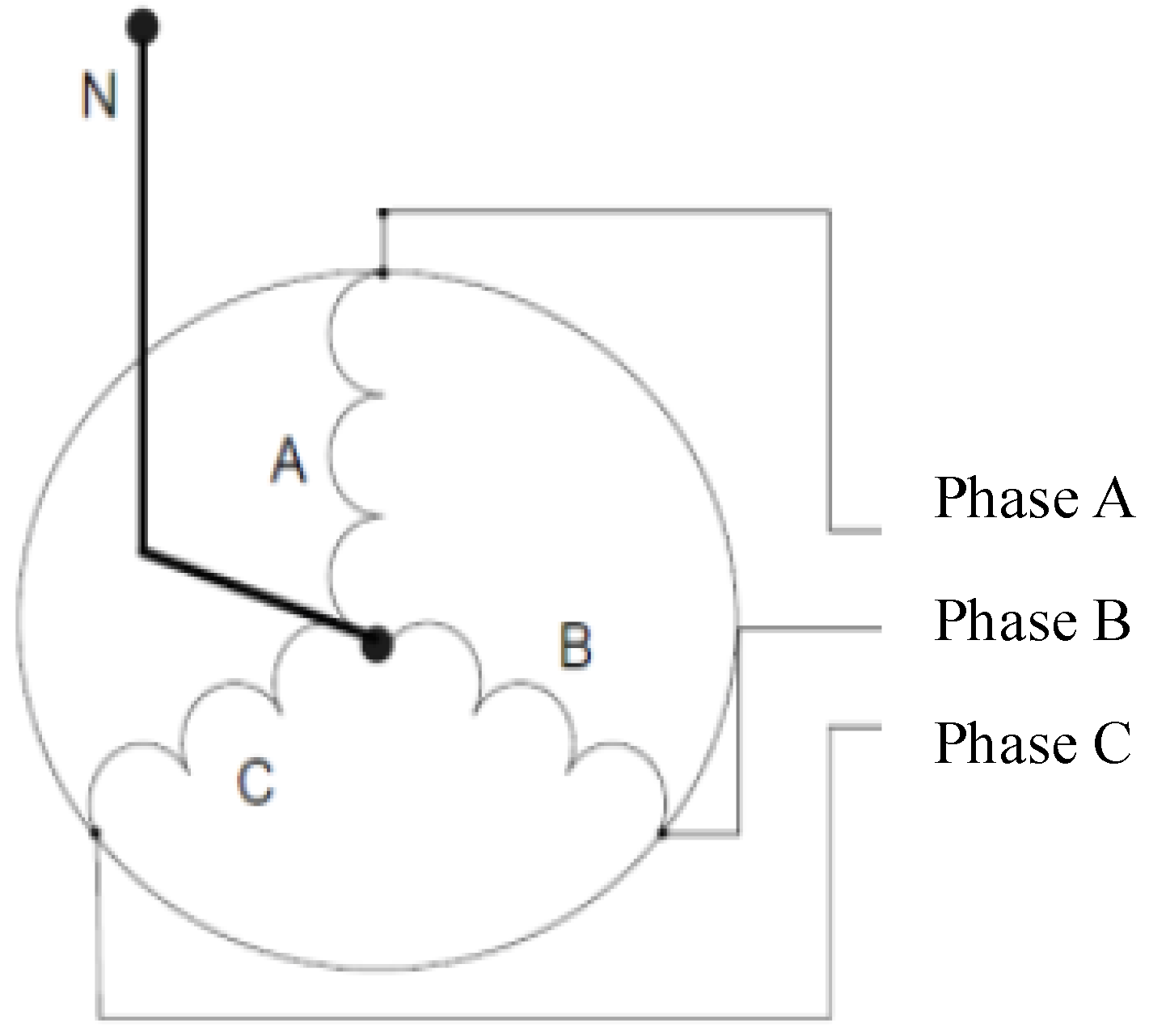
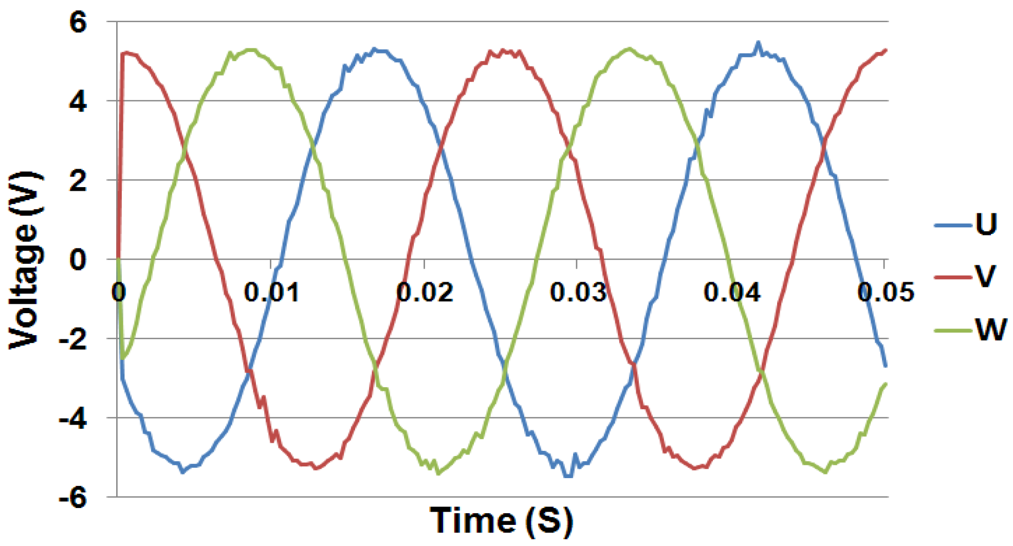
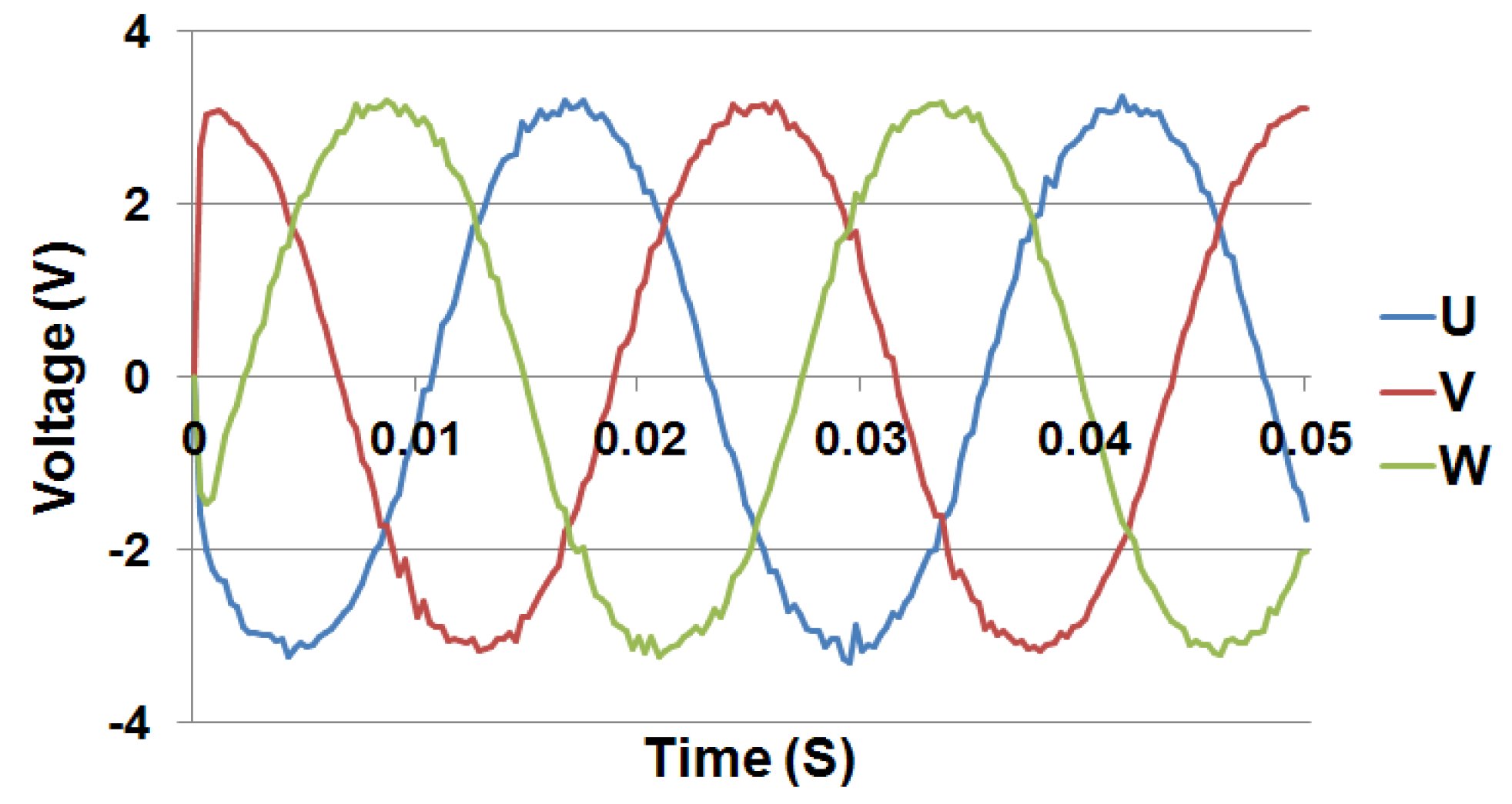
5.2. Power Generation for Single Phase

Table 3 presents the voltage generated during the test with the load of 100 Ω for a single phase. The impeller was driven with air through the pipe at room temperature.
Table 3. Power generation tests with a load of 100 Ω.
RPSVoltage (V)RPMI (A)Total (mW)
50.33000.0030.9
100.56000.0052.5
150.69000.0063.6
201.212000.01214.4
251.415000.01419.6
The 100 Ω capacitor was used to simplify the power generation calculation.

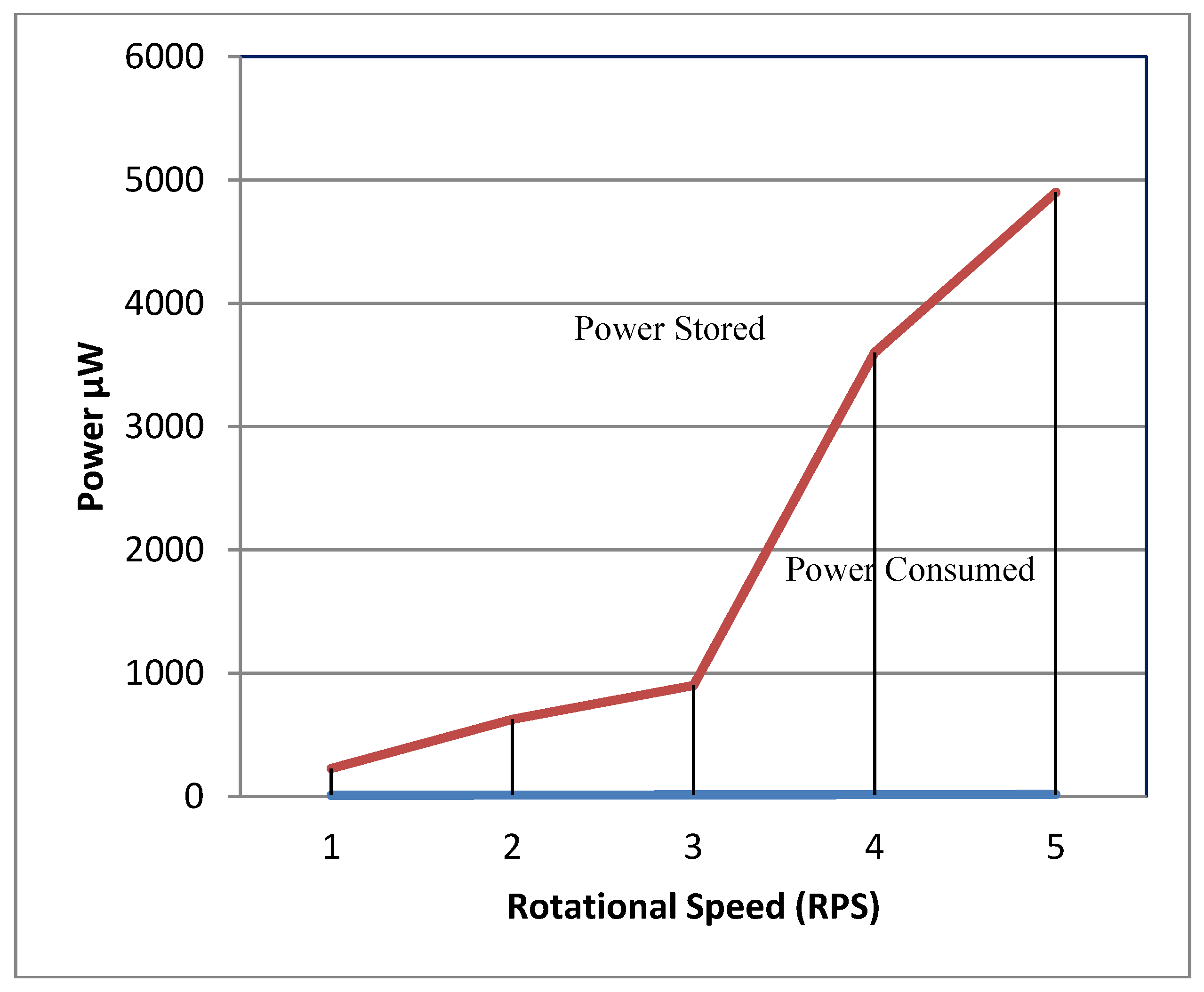
5.3. Power Consumption vs. Power Storage

A coreless AFPM generator was used to power a flowmeter. As shown on Figure 6, at a turbine rotational speed of 5 RPS the system was able to store the energy required by the meter measuring at the same speed. As the speed of the flow increases the energy consumption slightly increases but the energy stored increases exponentially enabling the system to store the excess energy in the capacitor.
Values for Figure 6 were calculated using Formula (6) and converted to μW along with the values obtained in the experiment from Table 4.
Table 4. Calculated power stored in one capacitor of 10 mF.
RPSVoltage (V)RPMC (mF)E (mJ)Total (µW)
50.3300100.45450
100.5600101.251250
150.6900101.801800
201.21200107.207200
251.41500109.809800
The capacitor used in this experiment is made of dielectric material to enhance the capacitance but suffers from the so-called dielectric loss which can account for up to half of the power input. The diode used also suffers from reverse voltage and forward current losses but this was small in comparison to the energy input, so it can be neglected. A 50% power loss was assumed. For example, at 25 RPS it was calculated a power stored in the capacitor of 9800 µW but only 4900 µW were assumed as available, the data was summarized on Figure 14.
Figure 14. Power consumption and storage.
Energies 07 03695 g014

5.4. Comparison of Electrical Charging and Power Consumption

To verify the concept, an experiment were conducted and repeated several times, with same results: it took 18 s to charge the capacitor of 10 mF to 3.3 VDC at an average of 10 RPS turbine rotational speed. Once the capacitor reached 3.3 VDC the generator was stopped and the flowmeter worked properly for 720 s measuring at about 20 RPS turbine rotational speeds.

6. Conclusions and Outlook

A digital and battery-free smart pipe-flow-meter was developed in this study. Three major technologies made this possible: a cog-resistance-free generator with high efficiency; an effective methodology to extract its energy and a low power consumption metering system for a new generation of flowmeters. In the system, a tiny portion of the kinetic energy from the fluid/air flow was extracted, stored in a capacitor and used. The resistance to the flow was negligible because of the very low power consumption as well as the coreless generator technology. Feasibility was demonstrated through repeated experiments: for air flowing in an 11 mm diameter pipe, 18 s of energy harvesting at 10 revolution-per-second (RPS) turbine speed, generated enough power for the flowmeter to operate for 720 s at 20 RPS, without battery or any other external power.
Smart flowmeters are equipped with wireless transceivers to transmit their data to a centralized unit especially in cases like leakage or backflow. Current transceivers are being developed with low power consumption in mind. The new Bluetooth low energy ones can work for up to four years off a single coil cell battery [19]. Considering the excess of energy being produced even at low flow speed a Bluetooth low energy device can be powered for as long as there is gas or water flowing through the flowmeter.

Acknowledgments

Sincere thanks go to the National Science Council of Taiwan under contract number: NSC 101-2218-E-168-001 Necessary financial support is greatly appreciated. Special thanks also to EPSON® for providing the demo set for this experiment. Appreciation also goes to Z.L. Gaing of Electrical Engineering Department, KaoYuan University, Taiwan, for his great instructions on the AFPM generator.

Author Contributions

A self-powered flowmeter with negligible resistance to the flow was developed, through the usage of a cog-free resistance generator, an ultralow power consumption metering system and a smartly designed energy storage IC circuit.

Nomenclature

AC
Alternating Current
AFPM
Axial-Flux-Permanent-Magnet
AMR
Anisotropic-Magnet-Resistance
CAGR
Calculated Annual Growth Rate
DC
Direct Current
PZ
Piezoelectric Material
GPRS
General Packet Radio Service
FEM
Finite Element Method
IC
Integrated Circuit
MCU
Microcontroller Unit
NMOS
N-Channel MOSFET
PEEK
Polyether Ether Ketone
PM
Permanent Magnet
PMOS
P-Channel MOSFET
RPS
Revolutions Per Second
RPM
Revolutions Per Minutes
RTC
Real Time Clock
SMS
Short Message Service
MOSFET
Metal–Oxide–Semiconductor-Field-Effect Transistor
UVLO
Under-Voltage Lock Out
WDN
Water Distribution Network

Conflicts of Interest

The authors declare no conflict of interest.

References

  1. Navigant Consulting, Inc. Smart Gas Meters Navigant Research. 2014. Available online: http://www.navigantresearch.com (accessed on 31 January 2014).
  2. Kolhare, N.R.; Thorat, P.R. An approach of flow measurement in solar water heater using turbine flow meter. Int. J. Eng. Res. Technol. 2013, 4, 1–4. [Google Scholar]
  3. Frenzel, F.; Grothey, H.; Habersetzer, C.; Hiatt, M.; Hogrefe, W.; Kirchner, M.; Lütkepohl, G.; Marchewka, W.; Mecke, U.; Ohm, M.; et al. Industrial Flow Measurement Basics and Practices; ABB Automation Products GmbH: Ladenburg, Germany, 2011. [Google Scholar]
  4. Thornton, J.; Sturm, R.; Kunkel, G. Water Loss Control Manual, 2nd ed.; McGraw-Hill Professional: New York, NY, USA, 2002; pp. 202–204. [Google Scholar]
  5. Artina, S.; Bragalli, C.; Erbacci, G.; Marchi, A.; Rivi, M. Contribution of parallel NSGA-II in optimal design of water distribution networks. J. Hydroinform. 2011. [Google Scholar] [CrossRef]
  6. Suribab, C.R. Differential evolution algorithm for optimal design of water distribution networks. J. Hydroinform. 2010, 12, 66–82. [Google Scholar] [CrossRef]
  7. Al-Omary, A.; El-Medany, W.; Al-Irhayim, S. Secure low cost AMR system based on GPRS technology. Int. J. Comput. Theory Eng. 2012, 4, 35–42. [Google Scholar]
  8. Britton, T.C.; Stewart, R.A.; O’Halloran, K.R. Smart metering: Enabler for rapid and effective post meter leakage identification and water loss management. J. Clean. Prod. 2013, 54, 166–176. [Google Scholar] [CrossRef]
  9. Wang, S.; Garcia, R. Development of a Self-Rechargeable Digital Water Flowmeter. J. Hydroinform. 2013, 15, 888–896. [Google Scholar] [CrossRef]
  10. Whittle, A.; Girod, L.; Preis, A.; Allen, M.; Lim, H.; Iqbal, M.; Srirangarajan, S.; Fu, C.; Wong, K.; Goldsmith, D. Waterwise@SG: A testbed for continuous monitoring of the water distribution system in Singapore. Water Disribution Syst. Anal. 2011. [Google Scholar] [CrossRef]
  11. SEIKO EPSON Corp. CMOS 16-bit Single Chip Microcontroller S1C17001 Technical Manual; SEIKO EPSON Corp: Taipei, Taiwan, 2012. [Google Scholar]
  12. Cavagnino, A.; Lazzari, M.; Profumo, F.; Tenconi, A. A comparison between the axial flux and the radial flux structures for PM synchronous motors. IEEE Trans. Ind. Appl. 2002, 38, 1517–1524. [Google Scholar] [CrossRef]
  13. Bumby, J.R.; Martin, R.; Mueller, M.A.; Spooner, E.; Brown, N.L.; Chalmers, B.J. Electromagnetic design of axial-flux permanent magnet machines. IEEE Proc. Electr. Power Appl. 2004, 151, 151–160. [Google Scholar] [CrossRef]
  14. Caricchi, F.; Crescimbini, F.; Honorati, O.; Bianco, G.L.; Santini, E. Performance of coreless winding axial-flux PM generator with power output at 400 Hz-3000 rev/min. IEEE Trans. Ind. Appl. 1998, 34, 1263–1269. [Google Scholar] [CrossRef]
  15. Gieras, J.F.; Wang, R.-J.; Kamper, M.J. Axial Flux Permanent Magnet Brushless Machines; Kluwer Academic Publisher: Dordrecht, The Netherlands, 2004. [Google Scholar]
  16. Lombard, N.F.; Kamper, M.J. Analysis and performance of an ironless stator axial flux PM machine. IEEE Trans. Energy Convers. 1999, 14, 1051–1056. [Google Scholar] [CrossRef]
  17. Wang, S.; Gain, Z.; Garcia, R.; Chang, P.; Cheng, C. Development of a self-power peak expiratory flow meter. Appl. Mech. Mater. 2013, 241–244, 576–580. [Google Scholar]
  18. Mitcheson, P.D.; Yeatman, E.M.; Rao, G.K.; Holmes, A.S.; Green, T.C. Energy Harvesting from Human and Machine Motion for Wireless Electronic Devices. Proc. IEEE 2008, 96, 1457–1486. [Google Scholar] [CrossRef] [Green Version]
  19. Gomez, C.; Oller, J.; Paradells, J. Overview and evaluation of Bluetooth low energy an emerging low-power wireless technology. Sensors 2012, 12, 11734–11753. [Google Scholar] [CrossRef]
  20. Linear Technology. LTC3588-1 Piezoelectric Energy Harvesting Power Supply Datasheet; Linear Technology: Milpitas, CA, USA, 2010. [Google Scholar]
  21. Whitaker, M. Energy Harvester Produces Power from Local Environment, Eliminating Batteries in Wireless Sensors. J. Analog Innov. 2010, 20, 1–36. [Google Scholar]

