Next Article in Journal
Advanced Energy Harvesting from Macroalgae—Innovative Integration of Drying, Gasification and Combined Cycle
Previous Article in Journal
Reliability-Based Structural Optimization of Wave Energy Converters
 
 
Addendum published on 2 July 2019, see Energies 2019, 12(13), 2547.
Article

Thermal Performance Evaluation of Two Thermal Energy Storage Tank Design Concepts for Use with a Solid Particle Receiver-Based Solar Power Tower

1
Mechanical Engineering Department, King Saud University, P.O. Box 800, Riyadh 11421, Saudi Arabia
2
George W. Woodruff School of Mechanical Engineering, Georgia Institute of Technology, Atlanta, GA 30332, USA
3
Sustainable Energy Technologies Center, King Saud University, P.O. Box 800, Riyadh 11421, Saudi Arabia
*
Author to whom correspondence should be addressed.
Energies 2014, 7(12), 8201-8216; https://doi.org/10.3390/en7128201
Submission received: 15 October 2014 / Revised: 15 November 2014 / Accepted: 26 November 2014 / Published: 9 December 2014

Abstract

:
This paper presents the results of an extensive study of two thermal energy storage (TES) systems. The goal of the research is to make solar energy cost-competitive with other forms of electricity. A small-scale TES system was first built. The inner to outer layers were made of firebrick (FB), autoclaved aerated concrete (AAC) and reinforced concrete brick (CB). The experiments were conducted at temperatures of up to 1000 °C for sustained periods of time. AAC was found to be prone to cracking at temperatures exceeding 900 °C; as a result, AAC was eliminated from the second TES system. The second, larger-scale TES system was subsequently built of multiple layers of readily available materials, namely, insulating firebrick (IFB), perlite concrete (PC), expansion joint (EJ), and CB. All of the surfaces were instrumented with thermocouples to estimate the heat loss from the system. The temperature was maintained at approximately 800 °C to approximate steady state conditions closely. The steady state heat loss was determined to be approximately 4.4% for a day. The results indicate that high-temperature TES systems can be constructed of readily available materials while meeting the heat loss requirements for a falling particle receiver system, thereby contributing to reducing the overall cost of concentrating solar power systems.

1. Introduction

Concentrating solar power with thermal storage system represents a distinctive option of utilizing solar energy because the thermal energy can be dispatched in a similar fashion as conventional thermal power plants to respond to variations in supply and demand. Among all of the technologies that are being advanced for solar thermal power generation systems, central receivers are recognized for their high thermal efficiency due to their high potential operating temperatures. Recently, researchers have put serious efforts in achieving higher operating temperatures in central receiver systems. Although high temperatures enhance the efficiency of thermal energy storage (TES), the choices of viable storage media become scarcer with elevated temperatures. The construction of a well-insulated TES system becomes important in such a high-temperature application because the thermal losses are anticipated to be higher, resulting in more substantial thermal cycling issues. However, the cost of such TES system should be minimized so that operating at higher temperatures can still be economically justified. In this scenario, the use of solid particles becomes a leading candidate for the TES system.
A multi-national research team is currently engaged in exploiting the potential of solid particles for use in a TES system. The study is conducted as a part of a U.S. Department of Energy (DOE)-funded SunShot project titled “High Temperature Falling Particle Receiver”, in which the goal is to demonstrate that the solid particles with temperatures higher than 650 °C can be stored in a small-scale system with a heat loss of less than 4% over an entire cycle. This heat loss can be shown to correspond to a heat loss of less than 1% over the same period for a large-scale system.
Thermal energy storage in solid particles has been studied by a number of research groups. The research originated in Sandia National Laboratories (SNL) in the early 1980s attempted to produce a direct absorption central receiver that is able to interface electric power and chemical production cycles with temperatures (>600 °C) higher than those possible with molten salt receivers [1]. The study examined the use of solid carriers as both a storage medium and a working fluid for high temperatures. In a subsequent feasibility study, a solar central receiver was built in which free-falling solid particles absorbed direct radiation and achieved high temperatures (>550 °C) [2]. The emphasis of the study was on the particle material selection and the receiver design. The study identified an inexpensive, alumina-based particle material that can operate even at temperatures of up to 1000 °C. The early work on the technical feasibility of the solid particle concept at SNL were reviewed and summarized by Falcone [3,4]. Optical characterization of master beads and other particle materials was conducted [5,6]. Some numerical and experimental studies were performed to understand the particle dynamics with and without heat transfer [7,8,9]. Researchers at SNL also considered other particulate materials for their solid particle receiver (SPR) concept [2,10]. These types of particles are engineered materials that exhibit high absorptance and/or durability while remaining suitable for operation at temperatures as high as 1000 °C. A number of theoretical investigations have been performed in various configurations on the internal fluid dynamics of the solid particles receivers [11,12,13,14]. Evans conducted a number of numerical studies to study the effect of particle temperature and the efficiency of energy absorption of the solid particle receiver [12,13].
Meier [14] conducted 2D computational fluid dynamics (CFD) simulations on the performance of a solid particle receiver in a pilot plant. Chen et al. [15] developed a 3D CFD model to study the influence of particle size and other operating conditions on the performance of solid particle receivers. Researchers at Aachen University and the German Aerospace Centre (DLR) introduced the concept of storing energy in quartz sand as a part of their work on air volumetric receivers [16,17]. In this design, sand is heated by direct contact with air and then flows to a hot storage bin, from which sand can later flow to a fluid bed cooler where it exchanges heat to generate steam. Numerical simulation of the heat exchanger demonstrated that the sand can achieve temperatures as high as 740 °C.
Heat transfer due to the charging-discharging of high temperature solid particles from such a hot bin is not a common engineering application. A number of studies related to transient heat transfer in TES systems with heat transfer fluids other than solid particles (sensible, latent), with packed/moving beds as storage, etc., were reported; however, none of the studies similar to the one presented in this paper were found in the literature. An early work of Kubie [18] numerically predicted the influence of insulating walls in steady-state heat transfer processes in stagnant beds of solid particles. Li et al. [19] numerically investigated a discharging process through a TES tank containing spherical capsules as storage and a new phase-change heat transfer fluid. A geometric model was used by Zhu et al. [20] for the numerical study of steady and transient hopper flows. However, they did not solve the energy equation for the investigated geometry. Mario et al. [21] investigated the transient charging-discharging process in a packed bed (spherical alumina particles) TES system. They numerically investigated oil, molten salt and air as potential heat transfer fluids.
The literature survey presented above indicates that most studies are related to steady/transient heat transfer between storage medium and heat transfer fluids during charging and/or discharging. No study was found that relates the heat loss from TES during charging-discharging. Furthermore, investigations of the heat loss characteristics of a TES bin using solid particle as both storage and heat transfer medium were not found. The literature review also reveals that, although a considerable effort has been made to identify appropriate granular particles for solar energy absorption and thermal energy storage, there are few available studies regarding the high temperature storage structures and their materials. The research effort described in this paper was performed to identify the most suitable designs and materials for the storage bins.

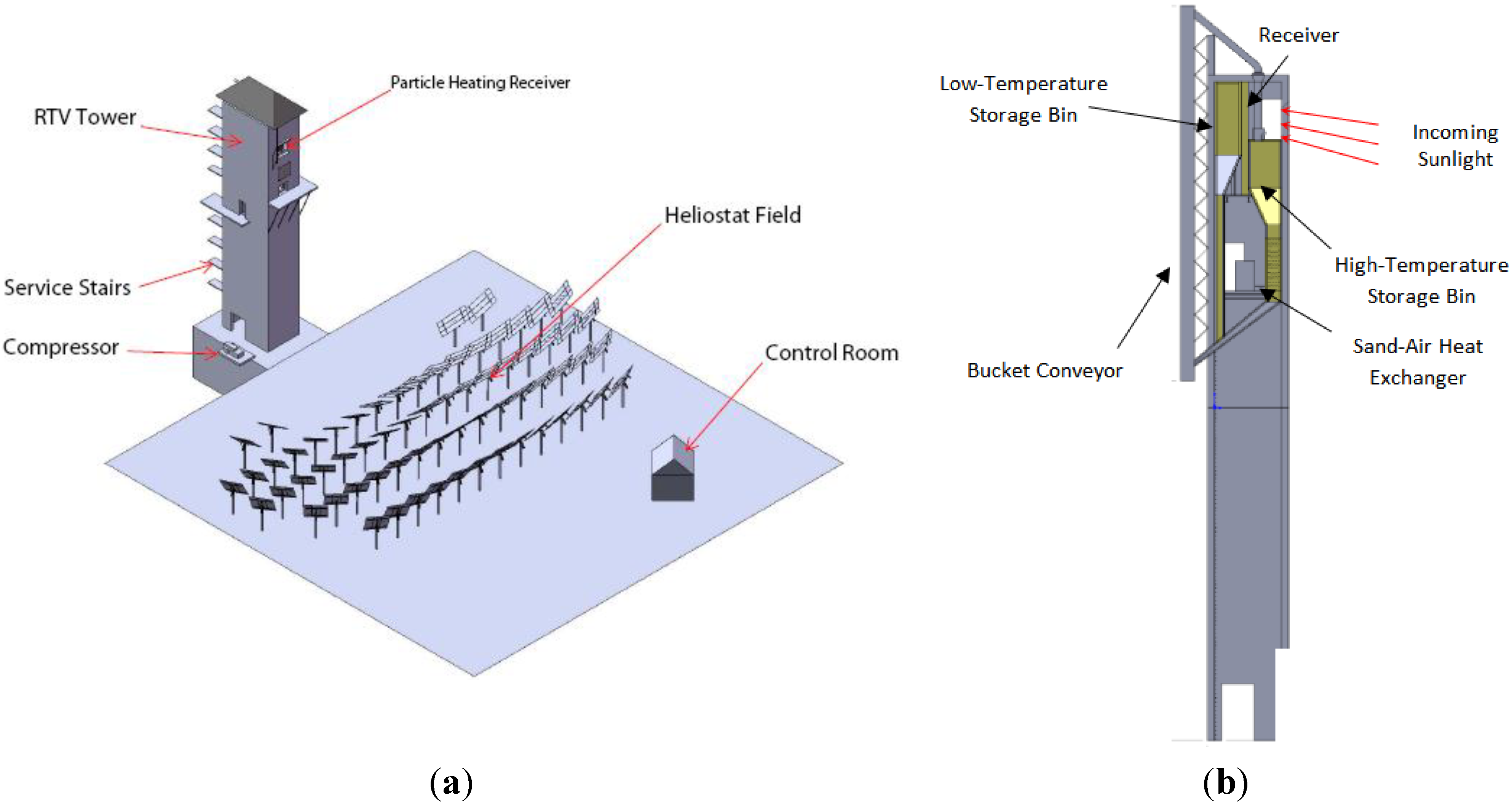
2. Overview of the Falling Particle Receiver Based Concentrated Solar Power Concept

Figure 1 shows the overall concept for the solar power tower system. The system involves the use of sand particles, which not only acts as the primary solar energy absorber but also serves the purpose of the thermal energy storage medium. In this concept, particles fall from a bucket-elevator hopper in the form of a curtain, located at the top of the receiver tower, past the location of the focused solar energy from the heliostat array. In this process, the particles become heated to temperatures that can approach 1000 °C. The hot sand then flows into a well-insulated tank (hot-bin), where it can be stored for later use. The sand exits the bottom of the tank and falls onto an air filled tube heat exchanger, which transfers thermal energy between the sand and air; subsequently, the hot air is fed into a suitable gas cycle. One variation of this system is shown in Figure 1, which includes a general view of the tower and the heliostat field and a detailed view of the central receiver concept. This work builds on the experience of other developers using sand as the proposed storage medium in trough plants, as well as the work of other investigators, such as work on the SPR concept that was introduced and tested at the National Solar Thermal Test Facility in SNL [15,22]. The proposed system is expected to overcome the issue of low solar energy absorption efficiency through the use of a novel cavity receiver design that has been tested at Sandia’s solar facility. Furthermore, a number of other novel features are being researched, including a patented mechanism for transferring heat from the sand to air [23], and a compact and integrated storage system that minimizes land construction costs and lift height.
Figure 1. Overview of the solid particle receiver (SPR) concept: (a) field layout of the pilot scale demonstration and (b) generic layout of components within the tower.
Energies 07 08201 g001

3. Material Selection for the Hot Bin

The tower design bin has several key aspects that require experimental development. A high temperature lining material is required that is capable of storing the heated sand with minimal heat loss while remaining structurally stable. A number of possibilities were investigated for proper material selection of the insulated hot bin, as presented in Table 1. The use of a steel or metal storage frame was found to be too soft at temperatures higher than 800 °C, and more exotic metals would quickly become unmanageably costly. This prompted an investigation into how kilns and foundries contain their high-temperature interior. Here, firebrick is a primary building material; although sound structurally, it is a very poor insulator. Insulating firebrick is also available; however, it sacrifices some of its strength for much improved insulation. While effective, insulating firebrick is still costly and insufficient for the overall insulation needs. An effective insulation layer was determined to be required. In this regard, a series of high-temperature insulating concretes are being tested. The first was aerated autoclaved concrete (AAC), and the second was perlite concrete (PC).
Table 1. Hot-bin material design concepts. FB: firebrick; CB: concrete brick; IFB: insulating firebrick; PC: perlite concrete.
Concept#Design descriptionAssessment
1Steel or metal frameNot suitable—Does not meet the high-temperature requirements
2Exotic metal frameNot suitable—Does not meet the cost targets
3Layers of FB + reinforced CBNot suitable—Not expected to meet the heat loss limit
4Layers of IFB + reinforced CBNot suitable—Strength is questionable; does not meet the cost targets
5Layers of FB + Perlite Concrete PC + reinforced CBWarrants further investigation
6Layers of IFB + Perlite Concrete PC + reinforced CBWarrants further investigation
To ensure proper insulation of the hot bin, it was of paramount importance to have materials with minimal thermal conductivities. Thermal conductivity measurements were performed using NETZSCH Heat Flow Meters HFM 436 (NETZSCH-Gerätebau GmbH, Selb, Germany), which measures the thermal conductivity over the range of 10 to 90 °C. Table 2 presents the results of the thermal conductivity measurements for insulating firebrick (IFB), AAC, PC, perlite refractory concrete (PRC), and expansion joint (EJ). The measurements demonstrate that the materials under consideration have low thermal conductivity; therefore, they can function well as insulation materials.
Table 2. Thermal conductivity measurements of the potential construction materials.
S#MaterialThermal conductivity (W/m·K)
1IFB0.17–0.2
2Autoclaved Aerated Concrete (AAC)0.11–0.15
3PC0.1–0.14
4Perlite Refractory Concrete (PRC)0.09–0.12
5Expansion Joint (EJ)0.038–0.05

4. First Scale Hot-Bin
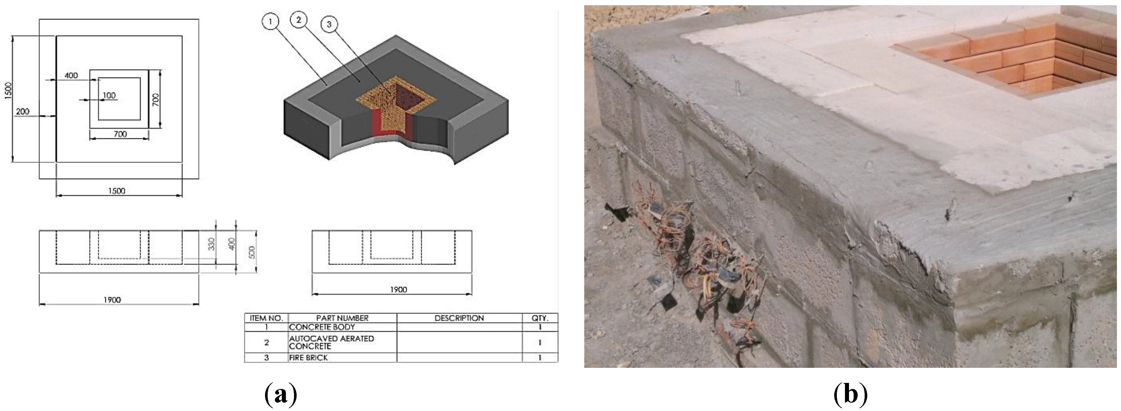
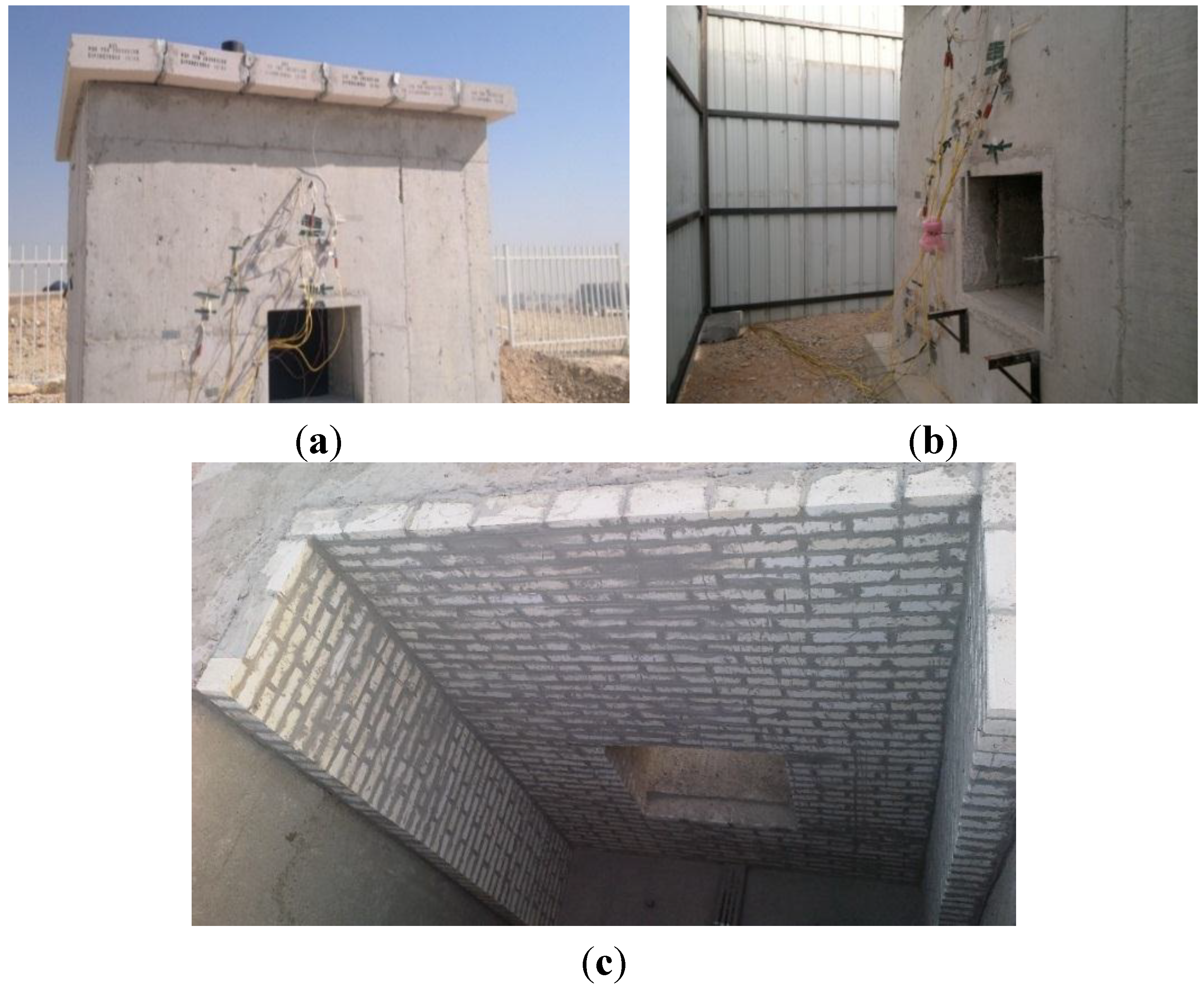
4.1. Construction

The storage bin walls are made of three layers: insulating firebrick, insulating concrete, and reinforced concrete. The first two materials are known to possess low thermal conductivity, thereby limiting heat loss considerably. The main advantage of this design is that the materials used are readily available and inexpensive; they are also capable of handling operation at high temperature. To test the refractoriness of this type of storage bin and measure the temperature distribution, a small-scale storage bin was built and tested. Figure 2 shows a drawing for basic experimental bins, as well as the first actual test bin that was built for this experiment.
As shown in Figure 2, the inner storage compartment is surrounded by thick layers of firebrick (FB), AAC, and reinforced concrete brick (CB). Two layers of AAC (I & II) were constructed to achieve the desired thickness. To simulate the high-temperature solid particles, a liquefied petroleum gas (LPG) burner was inserted inside the inner compartment of the storage bin. During the preliminary tests, the burner was able to maintain steady temperatures of up to 900 °C. The storage bin was instrumented with numerous thermocouples to accurately quantify the temperature distribution through the walls. Five thermocouples were placed in every layer of each wall at uniformly distributed locations to find the average temperature. High temperature Nextel insulated K-type thermocouples (accuracy ±0.75%) are used on both sides of the firebrick whereas perfluoroalkoxy (PFA) insulated K-type thermocouples (accuracy ±1.5 °C up to 375 °C) are used in the other layers. In the meantime, the flow of LPG from its tank to the burner was also measured continuously to determine the rate of energy introduced into the inner compartment.
Figure 2. Description of the thermal energy storage bin experimental apparatus: (a) engineering drawing, showing the dimensions of the bin and (b) photograph of the actual bin, showing the thermocouple wires.
Energies 07 08201 g002

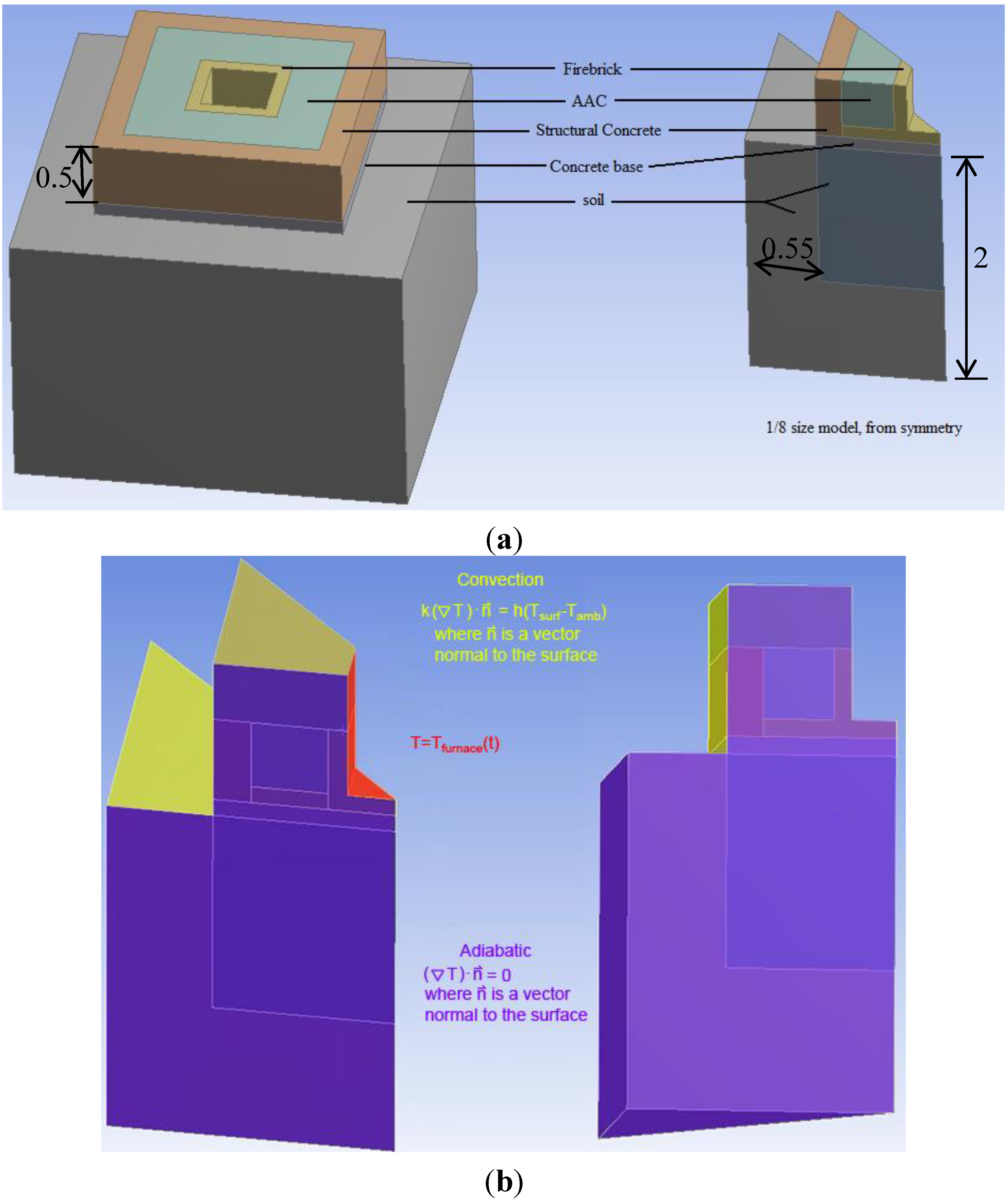
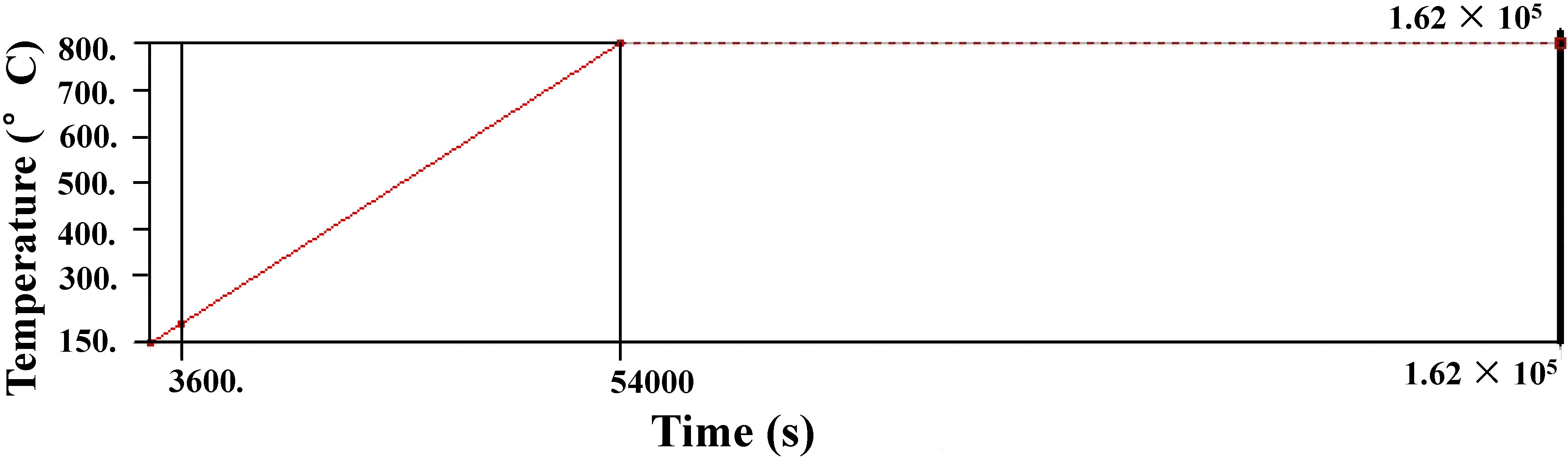
4.2. Computational Analysis

A finite element model was developed in the ANSYS workbench environment, and both transient and steady-state thermal analyses were performed. Figure 3a shows the geometry developed for the simulation (the AAC slab covering the top of the experimental fire pit was included in the model, but is not shown in the figure). Because the geometry and loading conditions are symmetric across several bisecting planes, only 1/8 of this geometry is required to solve for the temperature distribution. The reduced model is shown on the right in Figure 3a.
Figure 3b shows the boundary conditions used in the simulation. Each of the exposed surfaces of the bin, as well as the top soil surface, were given a convection boundary condition with a coefficient of 10 W/m2·K, and each of the outermost surfaces of the soil was given a constant-temperature boundary condition of 25 °C. The initial temperature for all materials was set to 17 °C. For the transient case, the temperature along the inside surface was ramped up to 800 °C and then held constant as shown in Figure 4. This approximates the furnace temperature as measured in the experiment.
Figure 3. (a) Geometry of the finite-element model (dimensions in m); (b) Boundary conditions applied to different surfaces.
Energies 07 08201 g003
Figure 4. Temperature boundary condition for inside surface.
Energies 07 08201 g004
For the transient analysis, ANSYS approximates a solution to the familiar transient heat equation in three spatial dimensions over each element:
ρ C ( T t + V x T x + V y T y + V z T z ) = q + x ( k x ( T ) T x ) + y ( k y ( T ) T y ) + z ( k z ( T ) T z )
Because the elements are static (Vx = Vy= Vz = 0), there is no heat generation ( q = 0), and the materials are considered isotropic (kx = ky = kz = k); as a result, this equation simplifies to:
ρ C ( T t ) = x ( k ( T ) T x ) + y ( k ( T ) T y ) + z ( k ( T ) T z )
where ρ is the density of the material, k is its thermal conductivity, and T is the temperature (a function of x, y, z, and t). The thermal conductivity of the perlite concrete region was a function of temperature. Table 3 shows the values which were used for the simulation [24]. This data is for a 1:6 mix of aluminate cement to perlite. The temperature gradients in the reinforced concrete, the firebrick, and the soil were expected to be fairly small because the perlite concrete had the greatest thermal resistance by far and would account for the largest temperature drop. Constant-value approximations were used for the thermal conductivities of these other materials at their respective experimental temperatures. The constant conductivity values used for the firebrick, reinforced concrete, and soil were 0.35 W/m·K, 2 W/m·K, and 0.265 W/m·K, respectively.
Table 3. Thermal conductivity of perlite concrete with temperature. Data from [24].
S#Temperature (°C)Thermal conductivity (W/m·K)
1190.660.131
2266.220.142
3316.430.147
4350.860.154
5418.130.157
6434.740.162
7568.630.177
8573.030.180
9753.880.203

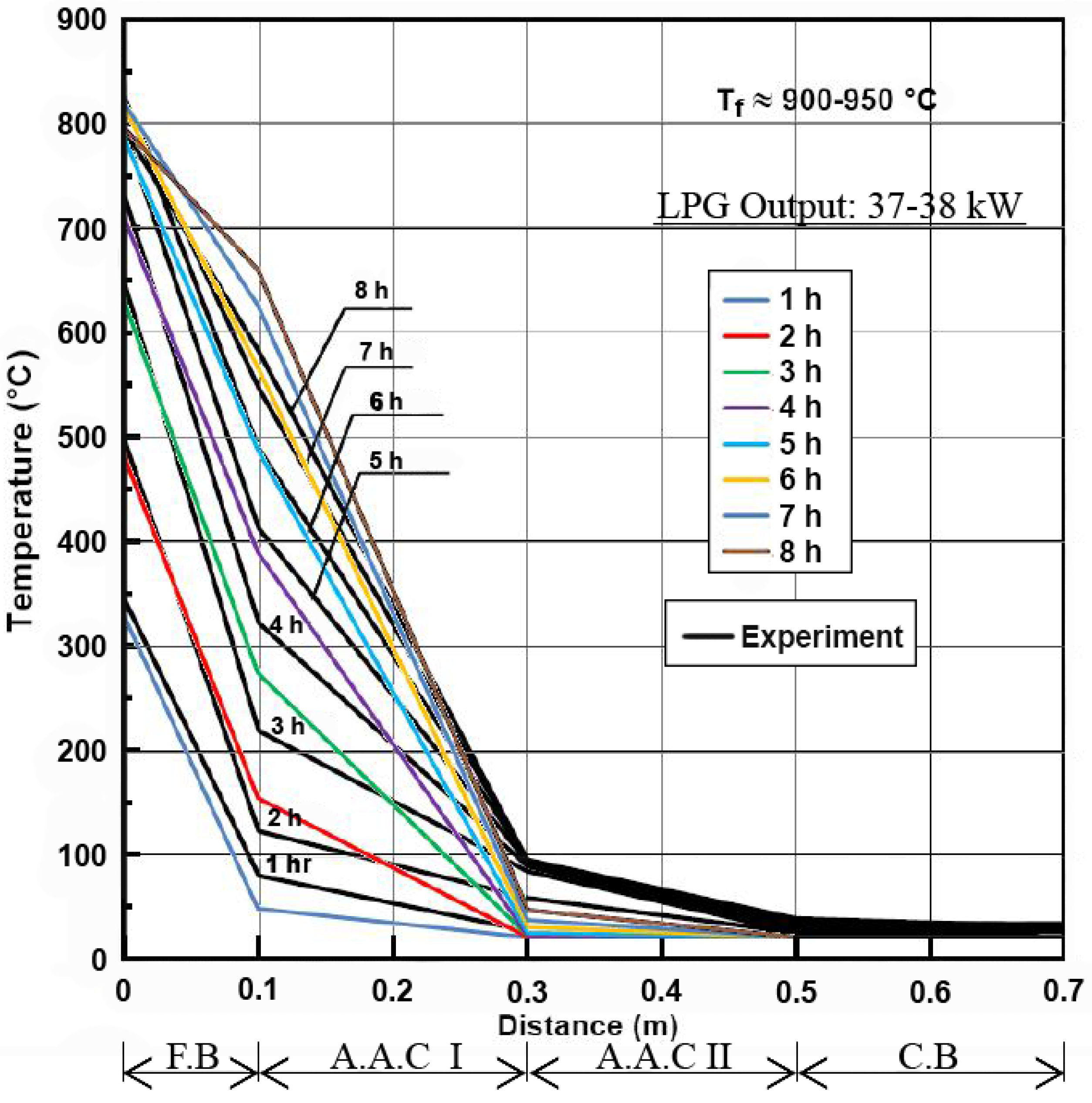
4.3. Results and Discussion

Figure 5 shows the history of the temperature distribution across the layers of the hot bin. The simulation results (in color) are superimposed over the experimentally measured temperature distribution at various times.
The distributions are in close agreement, indicating that the model and the assumed material properties are close to the actual values. The model’s temperature at a distance of 0.1 m increases faster than the experimental readings, whereas the temperature at 0.3 m increases more slowly. One possibility for this difference is that the high-temperature conductivity of the firebrick is slightly lower than the value taken from literature, while the high-temperature conductivity of the AAC is slightly higher.
Figure 5. Superposition of the experimental (black) and computational (in color) results for the temperature distribution across the layers of the hot bin.
Energies 07 08201 g005
The average rate of heat loss through the bin over 8 h was computed from the simulation results and was found to be 8750 W. The rate of heat loss was also computed from the steady-state simulation and found to be only 2350 W. In addition, the steady-state temperature distribution differed significantly from the distribution at 8 h. This discrepancy indicates that transient effects will be an important consideration when assessing thermal energy leak for the hot bin in the pilot building. The transient response was very slow because all the materials involved have low thermal diffusivities. A final important note was that the temperature of the reinforced concrete rises no higher than approximately 50 °C in the steady-state mode. The temperature of the total structural concrete (CB) should be kept below 66 °C to avoid long-term degradation, according to American Society of Mechanical Engineers (ASME)’s guidelines on containment vessels for nuclear reactors [25]. Local hotspots are permitted to reach 377 °C, and in the case of through tubes, a temperature of 93 °C is acceptable according to the ASME code for high-temperature reactor containment regarding CB.
During the experiment, the AAC on the exhaust hole acting as a chimney exhibited the clear formation of cracks around the hole (due to the approximately 900 °C exhaust gases) and on the surface of the AAC chimney (Figure 6).
Figure 6. Autoclaved concrete (AAC) cracking and heat damage.
Energies 07 08201 g006

5. Improved and Refined Scale Hot Bin
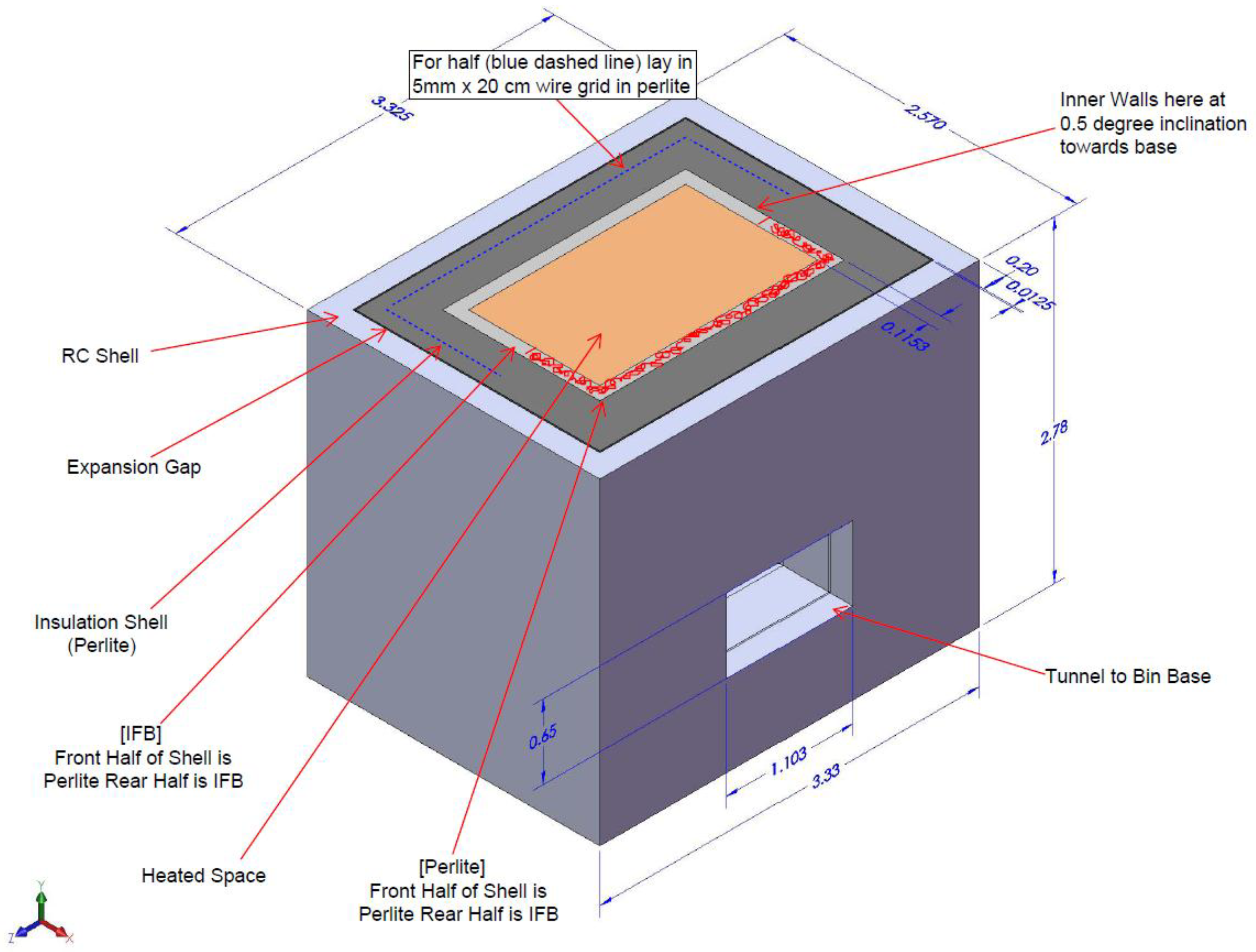
5.1. Construction

With this significant material issue at hand (Figure 6), the use of alternative hot bin materials was required. To this effect, AAC and FB are replaced by PC and IFB, respectively. Perlite concrete was chosen because such material has been tested in lab-scale furnaces up to 1000 °C cycles without cracking or crumbling for approximately 50+ hours’ worth of exposure. It was found, however, that at 100+ h of exposure, perlite using Portland cement became extremely fragile and degraded. According to the literature, concretes utilizing Portland cement begin to undergo physical and chemical dehydration, even at very low temperatures. Beginning at approximately 450 °C, the decomposition of the calcium hydroxide commences [26]. Portland cement-based concretes typically begin to lose strength (as measured by cold-compression tests) at temperatures above 300 °C [27]. This behavior was reflected in our lab samples tested at 1000 °C. Alternative concretes were therefore considered. Candidates include a mix of perlite, fireclay and Portland cement; aluminous cement with perlite aggregate; or firebrick mixed with large quantities of perlite. The perlite firebrick must be fired as individual bricks before placement–a procedure that may prove to be too expensive. The perlite/fireclay/Portland mixture may be placed monolithically, but has a higher conductivity and also a very clay-like texture before setting, so that it could not be easily poured. Aluminous cement has a proven refractory quality when mixed with water and could be poured in a manner similar to Portland cement.
There were a number of lessons learned from the first experiment, which are summarized as follows:
  • A test apparatus with a larger, more representative size was required to simulate the heat loss from the actual hot TES bin to be constructed within the 300 kW test facility at King Saud University (Riyadh, Kingdom of Saudi Arabia).
  • Despite the durability and low cost of firebrick, its thermal performance was not suitable due to its high thermal conductivity.
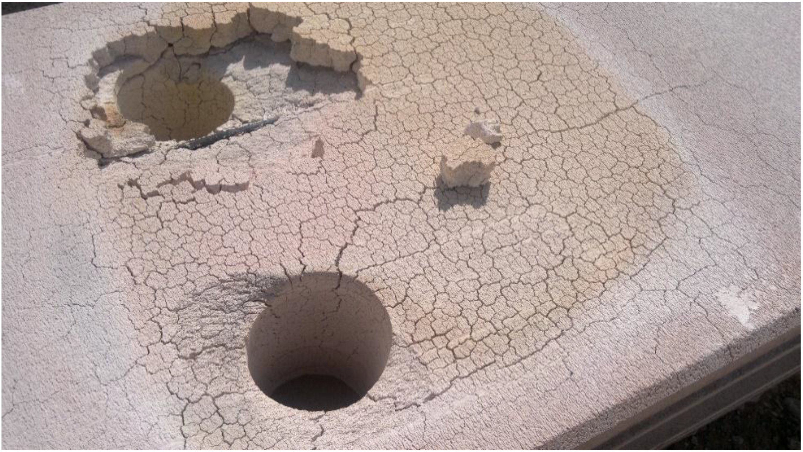
  • AAC is not suitable for use in future designs, due to the issue of cracking caused by high temperatures.
  • It was necessary to regulate the flow of LPG more tightly.
With these issues in mind, a new storage bin design was produced that is suitable for high temperatures, a sketch of which is shown in Figure 7.
Figure 7. Scaled thermal energy storage (TES) bin for the heat loss measurements and the materials testing (all dimensions are in meters).
Energies 07 08201 g007
In this design, FB and AAC are replaced by IFB and PC, respectively. However, this replacement is performed on only one half of the walls. In the other half of the walls, only PC is used. The reason for not having IFB on the second half is that we are interested in learning about the durability of PC when it is directly exposed to extreme temperatures. In both cases, RC remains as the external layer. The IFB and insulating concrete are known to possess low thermal conductivity, thereby limiting heat loss considerably. The main advantage of this design is that the materials used are readily available and inexpensive; they are also capable of handling operation at high temperature. Furthermore, an EJ was installed between PC and RC to relieve stress. A tunnel was also included in the design, partly to test the structure’s ability to handle an internal roof and to also serve as access to the TES bin base. In the tunnel, silicon carbide cross beams spaced a few inches apart serve as structural supports for the ceiling. In addition, a large LPG tank was installed on site to fuel a sustained fire within the bin. This large-scale tank ensured both a long experimental run time and a constant fuel flow rate for the tests. Figure 8 shows the TES bin before and after the installation of a shield. This shield was installed to minimize the effect of radiation and wind on heat loss measurements.
Figure 8. Pictures of the TES bin (a) before installing the shield and (b) after installing the shield; (c) inside picture of the hot bin.
Energies 07 08201 g008
The experiment was continuously run for nearly 45 h, during which the temperature was maintained at approximately 800 °C, and steady state conditions were closely approximated. The storage bin was instrumented with numerous thermocouples similar to first experiment. In addition, the flow of LPG from its tank to the burner was also measured continuously to determine the rate of energy introduced into the inner compartment. The total rate of heat output from the LPG was approximately 50–55 kW. The cylinders needed to be monitored on 30-min intervals to sustain the pressure for a fixed flow rate.

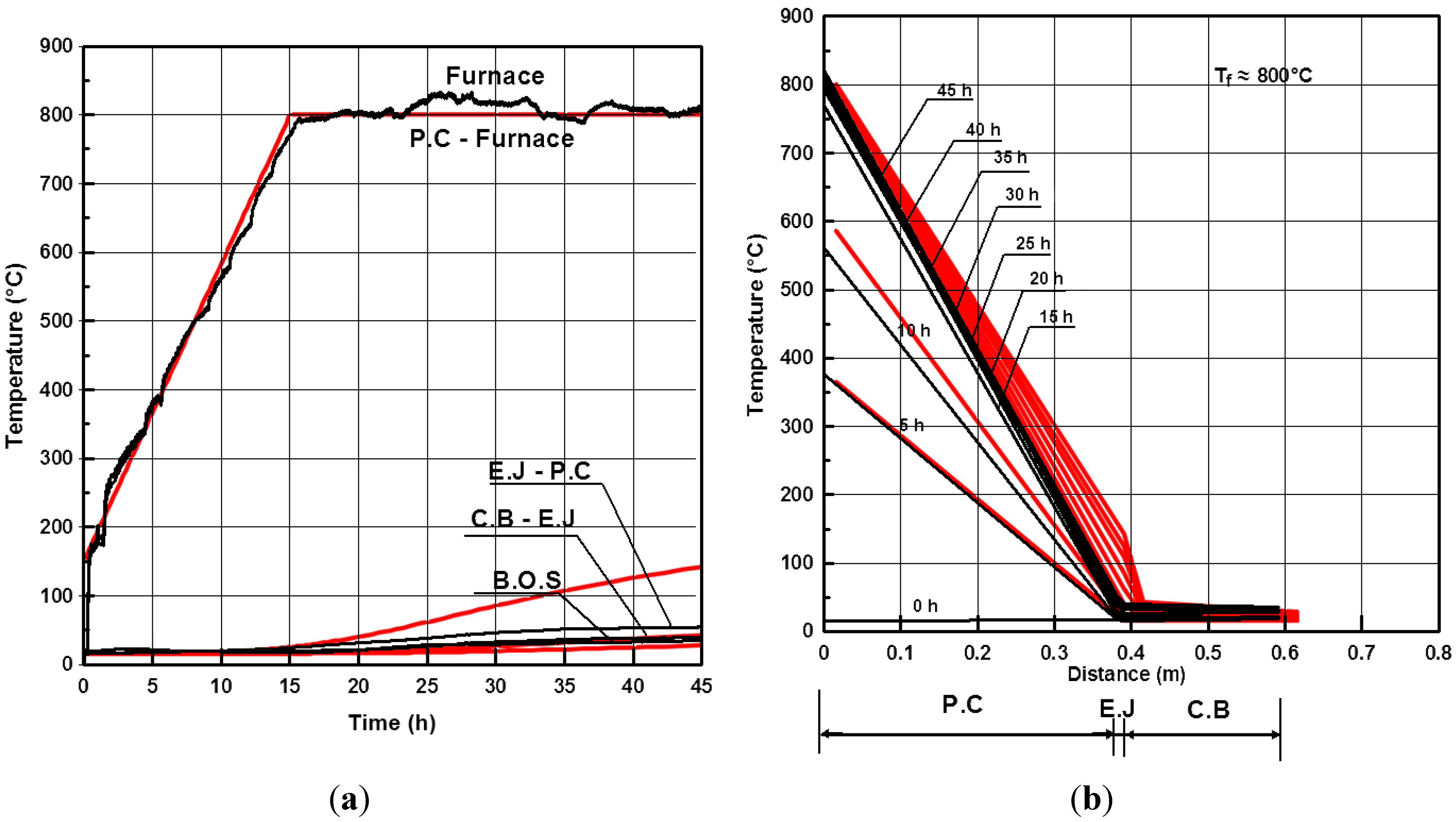
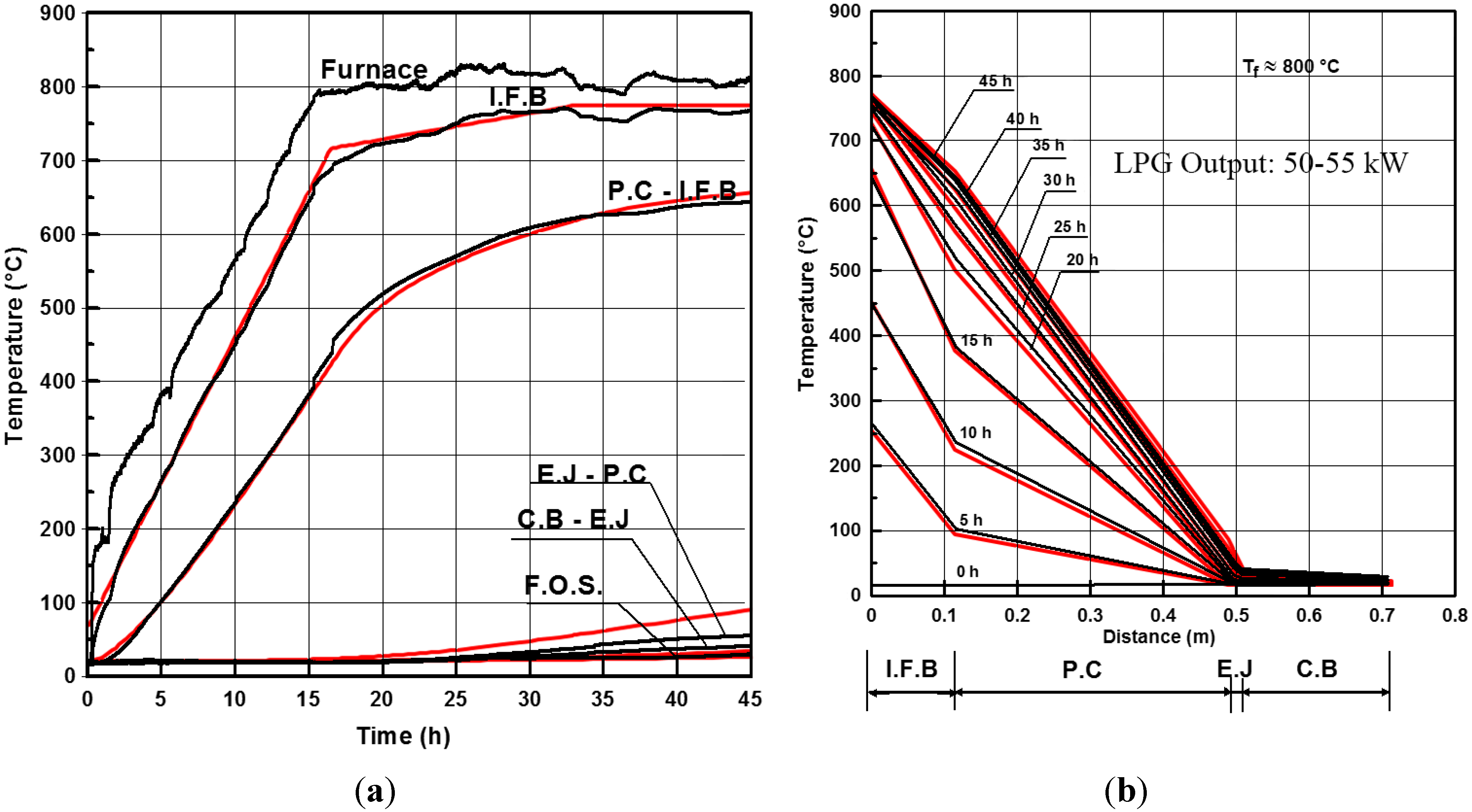
5.2. Results and Discussion

Similar to the previous case, a finite element model was developed in the ANSYS workbench environment, and both transient and steady-state thermal analyses were performed. Because the geometry and loading conditions are symmetric across a bisecting plane, only 1/2 of the geometry of Figure 7 is required to solve for the temperature distribution.
Figure 9 and Figure 10 show both the experimental and the simulation results for the temperature distributions determined for the system in the cases of with and without firebrick, respectively. The simulation and experimental results are in close agreement. The curves exhibit similar behavior and agree fairly well over the same timeframe. Both results indicate that the transient response time of the system is on the order of 2 days, and the simulation provides a reasonably close agreement of the temperature distribution during that transient startup.
Figure 9. Experimental and simulation results of the TES bin for the half that was covered with IFB: (a) temperature over time and (b) transient to steady-state temperature distributions across the layers (black lines represent the experimental data, and red lines represent the simulation results).
Energies 07 08201 g009
Figure 10. Experimental and simulation results of the TES bin for the half that was not covered with IFB: (a) temperature over time and (b) transient to steady-state temperature distributions across the layers (black lines represent the experimental data, and red lines represent the simulation results).
Energies 07 08201 g010
The steady state heat loss was found to be approximately 4.4%. Furthermore, inspection of the materials used to construct the TES system indicated that they remained intact and did not show signs of cracking or wearing. These results demonstrate that high-temperature TES systems can be constructed of readily available materials while meeting the heat loss requirements for a falling particle receiver system, thereby reducing the overall cost of concentrating solar power systems.

6. Conclusions and Future Recommendations

A systematic design process was used to develop a high-temperature thermal energy storage system. The favorable thermal performance of a TES bin constructed of readily available materials was demonstrated. Computer simulation results agree with the observed temperature history of the hot bin. The prototype exhibited superior performance and no degradation of the materials. This design can also be suitable for high-temperature applications other than the falling particle receiver. This experiment is still underway, and further tests will explore the effectiveness of the materials as insulators, particularly at high temperatures, as well as further examining their structural soundness at these elevated conditions. The TES bin had a rectangular shape; this shape was chosen for its simplicity and ease of instrumentation. However, this shape would not be suitable for large-scale TES bins due to its structural issues, especially at the corners. Therefore, it is preferable to test a different, more structurally robust design. It was determined that a round-shaped TES bin would be a suitable option to pursue and build for continued testing.

Acknowledgments

Authors are grateful to the Deanship of Scientific Research, Research Center of College of Engineering, King Saud University for providing financial support.

Conflicts of Interest

The authors declare no conflict of interest.

References

  1. Martin, J.; Vitko, J. ASCUAS: A Solar Central Receiver Utilizing a Solid Thermal Carrier; SAND-82-8203; Sandia National Laboratories: Livermore, CA, USA, 1982. [Google Scholar]
  2. Hruby, J.M. A Technical Feasibility Study of a Solid Particle Solar Central Receiver for High Temperature Applications; SAND-86-8211; Sandia National Laboratories: Livermore, CA, USA, 1986. [Google Scholar]
  3. Falcone, P.K. Technical Review of the Solid Particle Receiver Program; SAND-84-8229; Sandia National Laboratories: Livermore, CA, USA, 1984. [Google Scholar]
  4. Falcone, P.K.; Noring, J.E.; Hruby, J.M. Assessment of a Solid Particle Receiver for a High Temperature Solar Central Receiver System; SAND-85-8208; Sandia National Laboratories: Livermore, CA, USA, 1985. [Google Scholar]
  5. Stahl, K.A.; Griffin, J.W.; Matson, B.S.; Pettit, R.B. Optical Characterization of Solidparticle Solar Central Receiver Materials; SAND-85-1215; Sandia National Laboratories: Livermore, CA, USA, 1986. [Google Scholar]
  6. Stahl, K.A.; Griffin, J.V.; Matson, B.S.; Pettit, R.B. Optical Characterization of Solid Particle Solar Central Receiver Materials; SAND-85-0064; Sandia National Laboratories: Livermore, CA, USA, 1985. [Google Scholar]
  7. Hruby, J.M.; Burolla, V.P. Solid Particle Receiver Experiments: Velocity Measurements; SAND-84-8238; Sandia National Laboratories: Livermore, CA, USA, 1984. [Google Scholar]
  8. Hruby, J.M.; Steeper, R.; Evans, G.H.; Crowe, C.T. An Experimental and Numerical Study of Flow and Convective Heat Transfer in a Freely Falling Curtain of Particles; SAND-84-8714; Sandia National Laboratories: Livermore, CA, USA, 1986. [Google Scholar]
  9. Rightley, M.J.; Matthews, L.K.; Mulholland, G.P. Experimental characterization of the heat transfer in a free-falling-particle receiver. Sol. Energy 1992, 48, 363–374. [Google Scholar] [CrossRef]
  10. Siegel, N.; Kolb, G.J. Design and on-sun testing of a solid particle receiver prototype. In Proceedings of ASME 2nd International Conference on Energy Sustainability, Jacksonville, FL, USA, 10–14 August 2008.
  11. Evans, G.; Houf, W.; Grief, R.; Crowe, C. Gas-particle flowwithin a high temperature solar cavity receiver including radiation heat transfer. ASME J. Sol. Energy Eng. 1987, 109, 134–142. [Google Scholar] [CrossRef]
  12. Evans, G.; Houf, W.; Grief, R.; Crowe, C. Numerical Modeling of a Solid. Particle Solar Central Receiver; SAND-85-8249; Sandia National Laboratories: Livermore, CA, USA, 1985. [Google Scholar]
  13. Evans, G.; Houf, W.; Grief, R.; Crowe, C. Gas particle flow within a high temperature cavity including the effects of thermal radiation. Heat Transf. Denver 1985, 81, 245–253. [Google Scholar]
  14. Meier, A. A predictive CFD model for a falling particle receiver/reactor exposed to concentrated sunlight. Chem. Eng. Sci. 1999, 54, 2899–2905. [Google Scholar] [CrossRef]
  15. Chen, H.; Chen, Y.; Hsieh, H.T.; Siegel, N. Computational fluid dynamics modeling of gas-particle flow within a solid-particle solar receiver. ASME J. Sol. Energy Eng. 2007, 129, 160–170. [Google Scholar] [CrossRef]
  16. Warerkar, S.; Schmitz, S.; Goettsche, J.; Hoffschmidt, B.; Reißel, M.; Tamme, R. Air-sand heat exchanger for high-temperature storage. In Proceedings of ASME Energy Sustainability Conference, San Francisco, CA, USA, 19–23 July 2009.
  17. Baumann, T.; Boura, C.; Göttsche, J.; Hoffschmidt, B.; O’Connell, B.; Schmitz, S.; Zunft, S. Air-Sand Heat Exchanger Materials and Flow Properties. In Proceedings of the SolarPACES 2011, Granada, Spain, 20–23 September 2011.
  18. Kubie, J. Steady-state conduction in stagnant beds of solid particles. Int. J. Heat Mass Transf. 1987, 30, 937–947. [Google Scholar] [CrossRef]
  19. Li, X.-Y.; Li, L.; Yu, J.-W.; Liu, J.-Q.; Wu, Y.-Y. Investigation of the dynamic characteristics of a storage tank discharging process for use in conventional air-conditioning system. Sol. Energy 2013, 96, 300–310. [Google Scholar] [CrossRef]
  20. Xu, C.; Li, X.; Wang, Z.; He, Y.; Bai, F. Effects of solid particle properties on the thermal performance of a packed-bed molten-salt thermocline thermal storage system. Appl. Therm. Eng. 2013, 57, 69–80. [Google Scholar] [CrossRef]
  21. Mario, C.; Giorgio, C.; Pierpaolo, P.; Fabio, S. Numerical investigation of a packed bed thermal energy storage system with different heat transfer fluids. Energy Procedia 2014, 45, 598–607. [Google Scholar] [CrossRef]
  22. Ho, C.K.; Khalsa, S.S.; Siegel, N.P. Modeling on-sun tests of a prototype solid particle receiver for concentrating solar power processes and storage. In Proceedings of the ASME 2009 3rd International Conference on Energy Sustainability, San Francisco, CA, USA, 19–23 July 2009.
  23. Al-Ansary, H.; El-Leathy, A.; Al-Suhaibani, Z.; Al-Zahrani, S.; Jeter, S.; Abdel-Khalik, S.; Sadowski, D.; Golob, M. Solid Particle Receiver with Porous Structure for Flow Regulation and Enhancement of Heat Transfer. U.S. Patent 20130068217 A1, 21 March 2013. [Google Scholar]
  24. Hansen, W.; Livovich, A. Thermal conductivity of refractory insulating concrete. J. Am. Ceram. Soc. 1953, 36, 356–362. [Google Scholar] [CrossRef]
  25. Ashar, H.; Scott, B.; Artuso, J.F.; Stevenson, J.D. Code for concrete reactor vessels and containments. In Companion Guide to the ASME Boiler and Pressure Vessel, 3rd ed.; American Society of Mechanical Engineers: New York, NY, USA, 2009. [Google Scholar]
  26. Schneider, U. Verhalten von beton bei hohen temperaturen. In Deutscher Ausschuss fuer Stahlbeton; Wilhelm Ernst & Sohn: Munich, Germany, 1982. (In German) [Google Scholar]
  27. Petzold, A.; Röhrs, M. Concrete for High Temperature; Maclaren and Sons: London, UK, 1970. [Google Scholar]

