Article

Influence of Different Rotor Teeth Shapes on the Performance of Flux Switching Permanent Magnet Machines Used for Electric Vehicles

School of Automation, Beijing Institute of Technology, Beijing 100081, China
*
Author to whom correspondence should be addressed.
Energies 2014, 7(12), 8056-8075; https://doi.org/10.3390/en7128056
Submission received: 10 October 2014 / Revised: 12 November 2014 / Accepted: 24 November 2014 / Published: 1 December 2014

Abstract

:
This paper investigated a 12-slot/11-pole flux switching permanent magnet (FSPM) machine used for electric vehicles (EVs). Five novel rotor teeth shapes are proposed and researched to reduce the cogging torque and torque ripple of the FSPM machine. These rotor teeth shapes are notched teeth, stepped teeth, eccentric teeth, combination of notched and stepped teeth, and combination of notched and eccentric teeth. They are applied on the rotor and optimized, respectively. The influences of different rotor teeth shapes on cogging torque, torque ripple and electromagnetic torque are analyzed by the 2-D finite-element method (FEM). Then, the performance of FSPMs with different rotor teeth shapes are compared and evaluated comprehensively from the points of view of cogging torque, torque ripple, electromagnetic torque, flux linkage, back electromotive force (EMF), and so on. The results show that the presented rotor teeth shapes, especially the combination of stepped and notched teeth, can greatly reduce the cogging torque and torque ripple with only slight changes in the average electromagnetic torque.

Graphical Abstract

1. Introduction

As the number of vehicles increases globally, the energy crisis and environmental pollution have become drastic issues which restrict the development of the world auto industry. Undoubtedly, electric vehicles (EVs) with clean and low energy consumption are one of the best solutions of these problems and have received attention from all around the world. As the key part of EVs, different driveline types have been tried in EVs. Especially, the direct driveline with in-wheel machine is generating more and more interest. It can omit the clutch, the reduction gear and the differential gear. Because in-wheel machines are aimed to provide the traction of EVs directly, they should have high power density, high efficiency and perfect torque characteristic.
The flux switching permanent magnet (FSPM) machine is a potential candidate for the in-wheel machine. It can generate sufficient torque and power density, especially under starting and climbing conditions [1,2,3]. Its high power density characteristics are similar to those of permanent magnet (PM) machines [4,5,6,7,8]. Both windings and PMs are installed on the stator. This structure can avoid both the influence of centrifugal force on PMs and the problem of PM demagnetization caused by heat dissipation issues. As the waveform of the back electromotive force (EMF) is a sine wave, it is preferable to drive the FSPM machine in the brushless alternating current mode. Magnet accumulation effect is generated by neighboring PMs with opposite directions, which can reduce the volume of the machine, lessen the number of the PMs and decrease the machine cost. Different from common PM machines having PMs and armature windings magnetically in series, FSPM machines having PMs and armature windings magnetically in parallel lead to high flux weak capability, which is suitable for a wide speed range [9,10]. In particular, after hybrid excitation flux-switching machines were proposed, the flux linked in the armature windings per phase can be increased or reduced according to the operational status requests, which makes the magnetic field easily adjusted [11,12,13]. The fault-tolerant capability of FSPM machines has also been a hot topic in recent years, FSPM machines with fault-tolerant capability can continue to operate under open circuit and short circuit fault conditions [14,15,16,17]. To sum up, because of the FSPM machine’s simple structure, good controllability, high power density and fault-tolerant performance, it is a good selection for driving EVs.
However, the FSPM machine suffers from great slot effects and serious partial saturation due to its own double salient structure, which causes high cogging torque and torque ripple. Numerous methods have been researched for reducing cogging torque and torque ripple considering either the machine design or control aspects. In the machine design aspect, pole and slot matching is a common method to improve the torque performance of machines and it can be directly used in FSPM machines [18,19]. Both finite-element method (FEM) results and experimental tests show that the rotors with odd numbers have lower torque ripple than the rotors with even numbers when the stator structures are the same. Optimization of PM shape is a typical method to improve the torque characteristics of traditional PM machines [20,21]. However, because the PMs are inserted into stator teeth, optimizing the PM shape is not a suitable approach for FSPM machines. Optimizing the rotor structure is however a favorable method for FSPM machines. Rotors with stepped skew were adopted in [22,23] to reduce the cogging torque and torque ripple under various load conditions. Various kinds of notching schemes and their influence on cogging torque are evaluated in [24,25]. It is revealed that the notches effectively reduce torque ripples, but the average torque decreases as well. In order to have a maximum average torque with minimum ripple content, notches with exponential variation profile are imposed [25]. The multi-tooth structure is able to diminish the reluctance of magnetic circuit, which can improve the average torque, reduce the cogging torque and torque ripple [26,27]. The new laminated structure proposed in [28] can decrease magnetic saturation at the edges of stators and rotor teeth and lead to lower cogging torque and higher torque density. In the control aspect, injecting harmonic current or adjusting the current of normal phases can compensate torque ripple [29,30,31], but a sensitive and reliable sensor is needed to confirm the amplitude and angle of the current, and hence the complexity of the entire control system is increased. Optimizing the machine structure can either reduce the cogging torque or reduce the total harmonic distortion (THD) and hence torque ripple, so the machine design method is usually better than the control method.
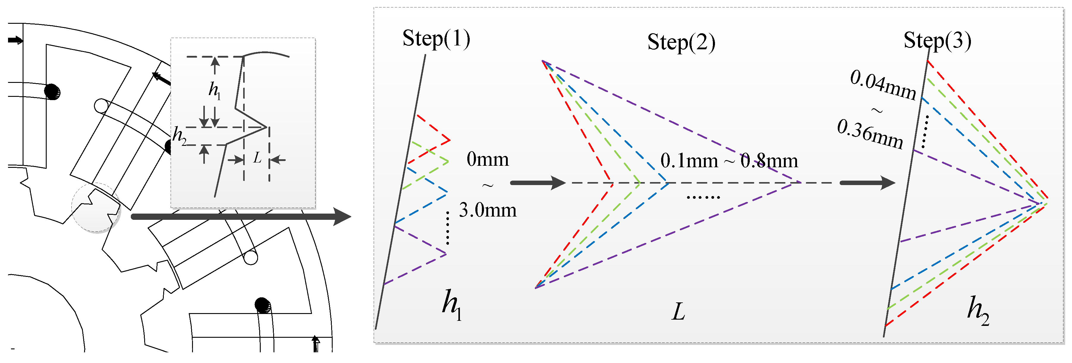
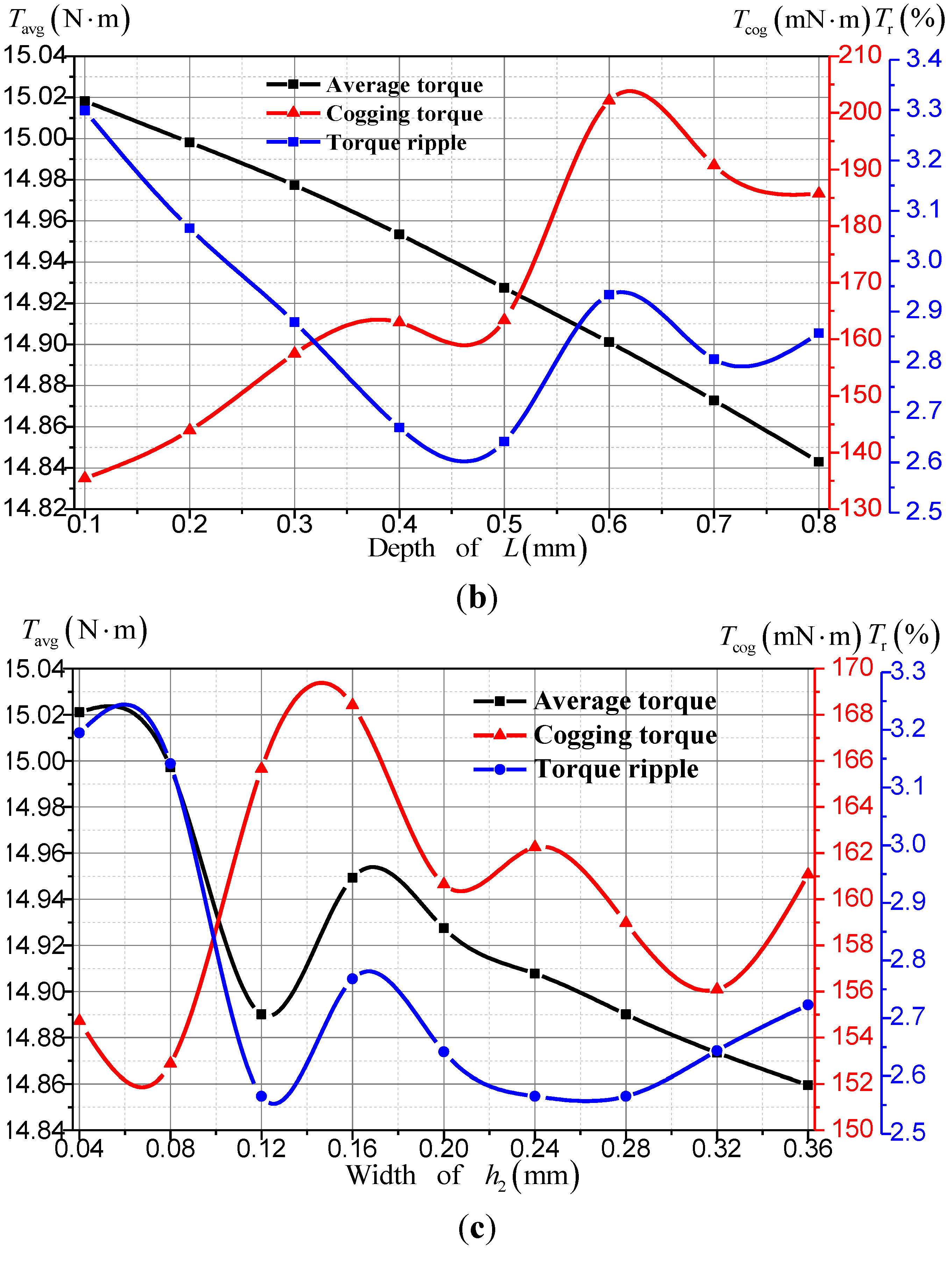
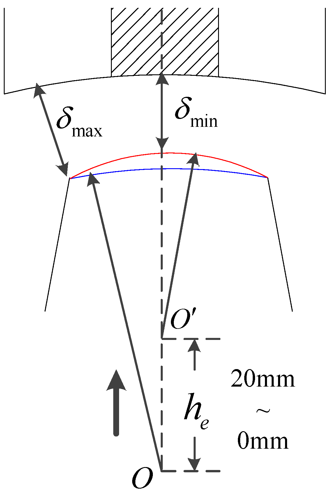
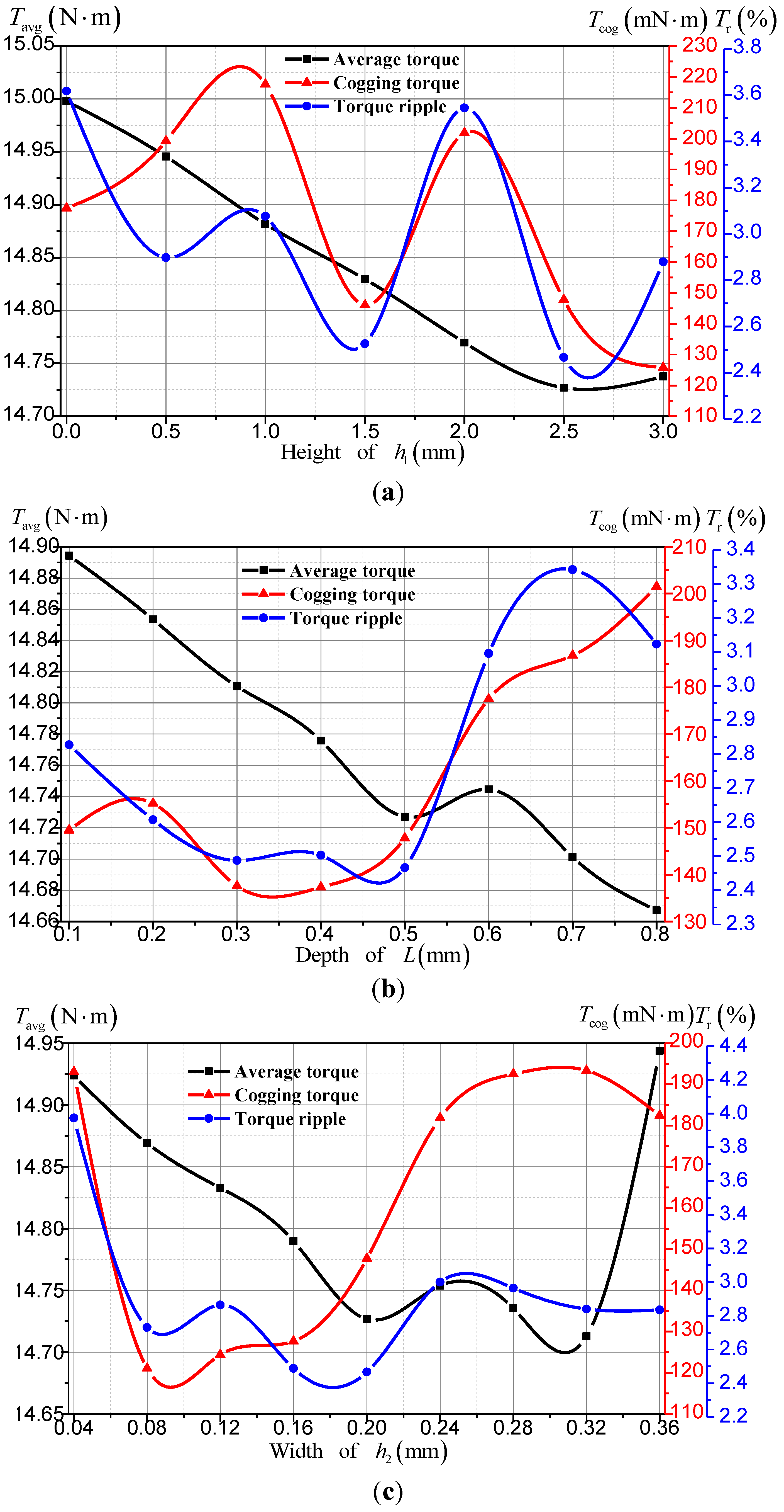
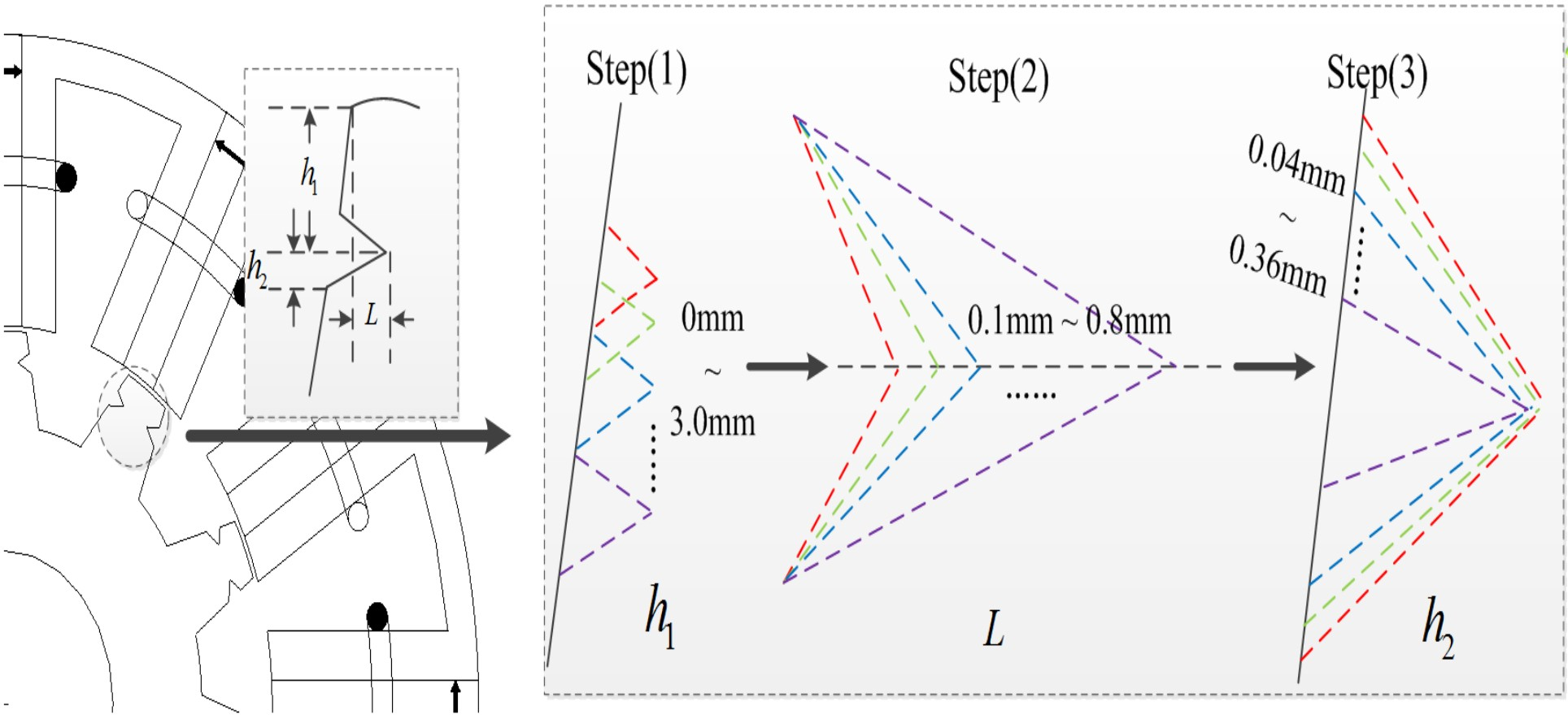
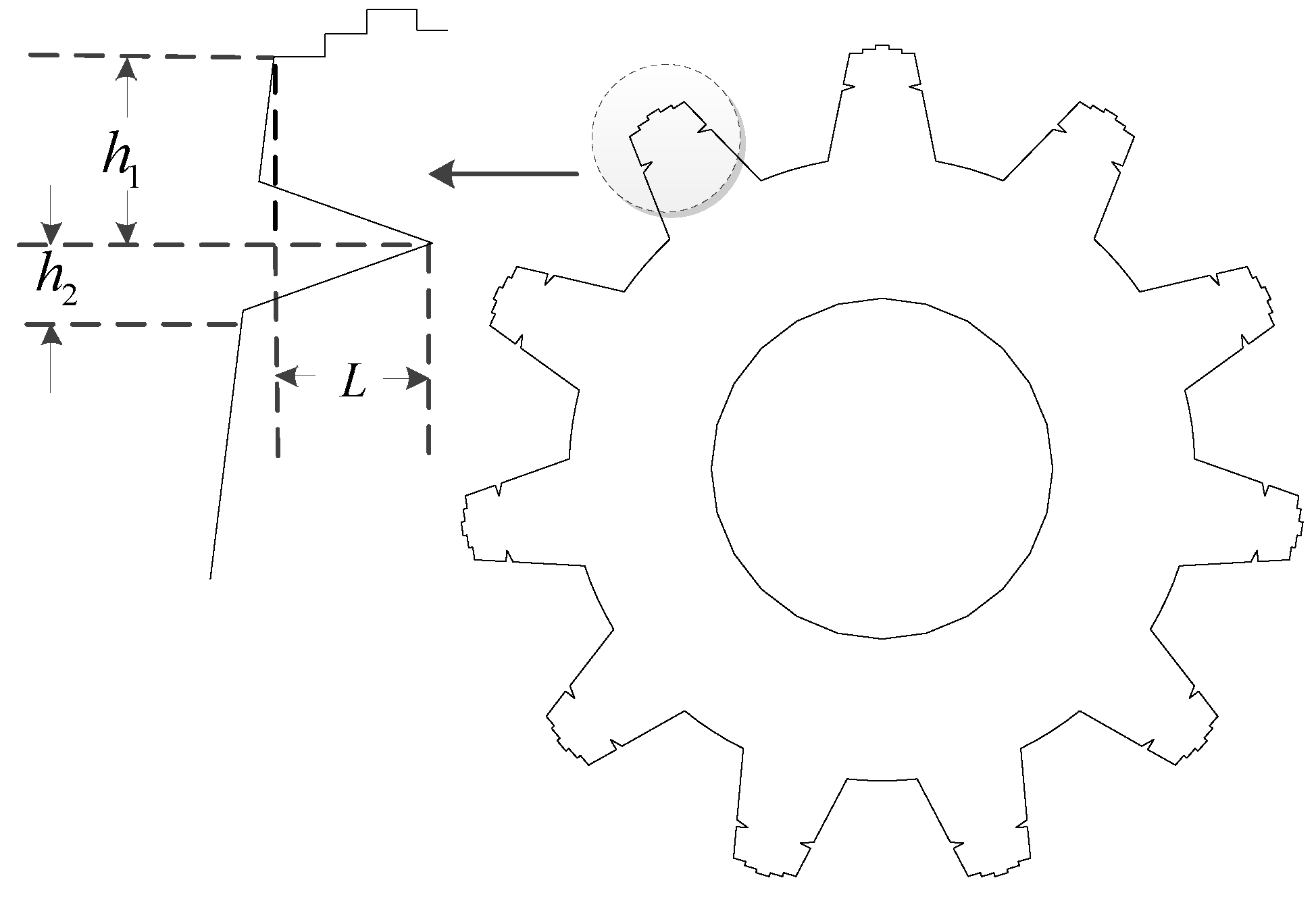
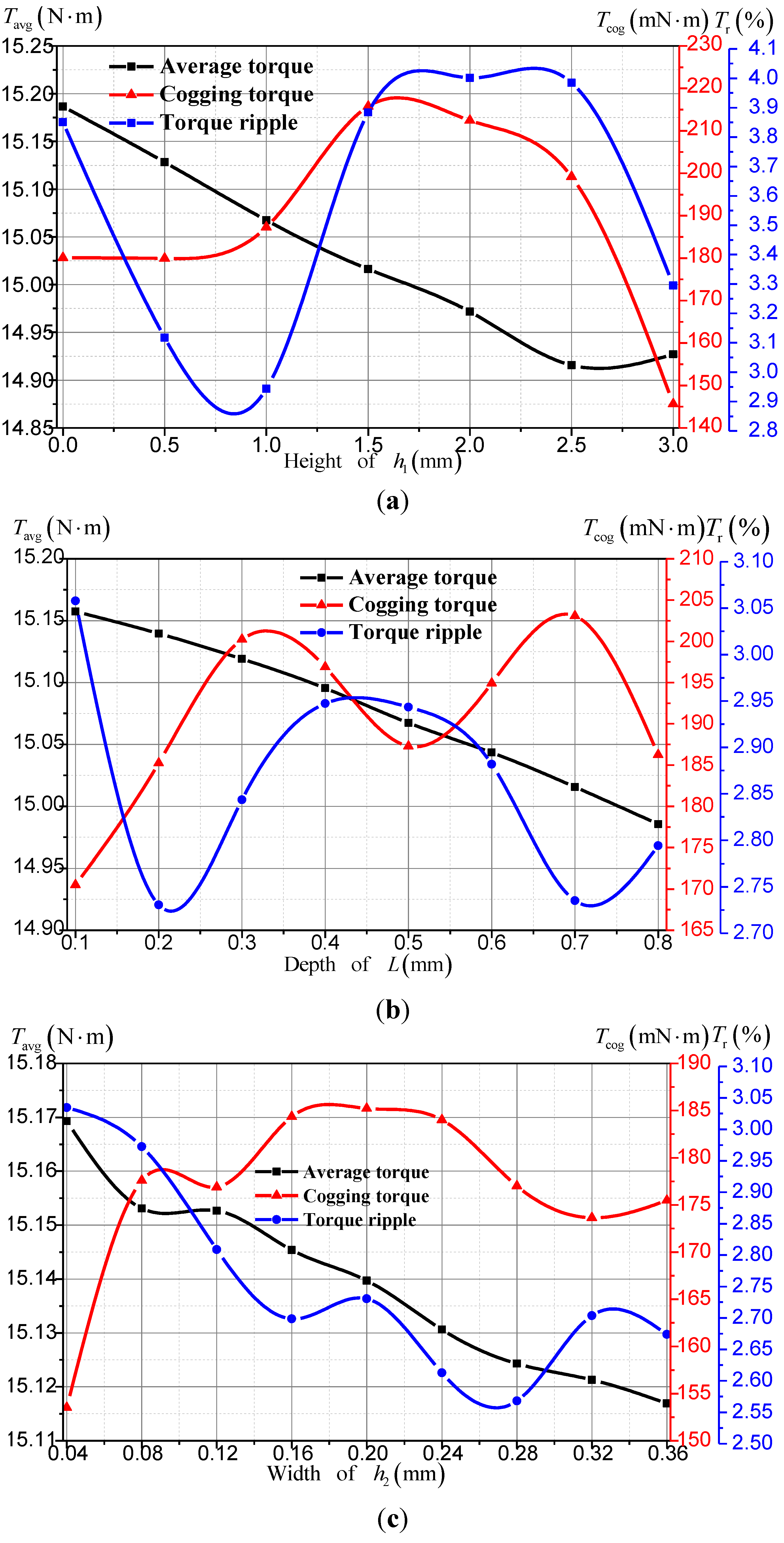
Considering that the stator structure of a FSPM machine is more complex, a relatively simpler rotor is selected to implement the improvement of torque characteristics of the FSPM machine in this paper. Firstly, the main parameters of FSPM machine are introduced. Secondly, the torque characteristics are analyzed. Under the premise of unchanging the stator’s structure, five novel rotor teeth shapes are proposed. Thirdly, the influences of different rotor teeth shapes on cogging torque, torque ripple and electromagnetic torque are analyzed by 2-D FEM using a commercial software package, Ansoft Maxwell. Finally, the performances of FSPMs with different rotor teeth shapes are compared and discussed based on cogging torque, torque ripple, electromagnetic torque, flux linkage, back EMF, and so on. The effects of different rotor teeth shapes are evaluated.

2. Machine Topologies and Torque Analysis

2.1. Flux Switching Permanent Magnet Machine Main Parameters

A 12-slot/11-pole FSPM machine used for in-wheel EV drive is designed as the initial analysis scheme, as shown in Figure 1.
Figure 1. Schematic of the proposed flux switching permanent magnet (FSPM) machine: (a) all poles wound cross section; and (b) one model.
Energies 07 08056 g001
The main design parameters of the machine are the ratio of the inner diameter to outer diameter of the stator (the split ratio) and the ratio of the rotor pole width to the stator pole width. The former ratio varies in the range of 0.55–0.6 and the latter varies in the range of 1.4–1.6. Detailed specifications are presented in Table 1.
Table 1. Main design parameters of the FSPM.
SymbolMachine parameterValueUnit
PPhase number3-
NsStator pole number12-
NrRotor pole number11-
NCoil number per stator slot78-
PMMagnet materialNTP40UH-
BrMagnet remanence (20 °C)1.26T
DsoStator outer diameter132mm
DroRotor outer diameter72mm
gAir gap length0.3mm
bmMagnet thickness4.75mm
hpRotor tooth height9.5mm
laMachine stack length59mm
nrRated rotational speed600rpm
TraRated output torque15N·m
IaPeak value of rated phase current15.4A
UdcDC link voltage110V

2.2. Torque Analysis

The torque curves of the FSPM machine excited with various current amplitudes (3.85–30.8 A) and inner power factor angles (−90°–90°) are shown in Figure 2.
Figure 2. Electromagnetic torques of the FSPM machine with different current amplitudes and inner power factor angles.
Energies 07 08056 g002
The B-H curve of the iron core is shown in Figure 3. It can be seen that the torque growth rate is less than the current growth rate due to the saturation of the iron core. The torque reaches its maximum value at around inner power factor angle of 15°.
Figure 3. The B-H curve of the lamination B35A300.
Energies 07 08056 g003
By the principle of virtual displacement, the electromagnetic torque Tem of the FSPM machine can be derived by co-energy [23], the Wcoenergy can be expressed as:
W coenergy ( i , θ ) = i T ψ ( i , θ ) W field ( i , θ ) = i T [ ψ P M ( θ ) + L ( θ ) i ] [ W PM ( θ ) + 1 2 i T L ( θ ) i ] = i T ψ PM ( θ ) + 1 2 i T L ( θ ) i W PM ( θ )
where i is the excitation current; θ is the rotor position; L(θ) is the inductance; ψ(i,θ) is the flux linkage; Wfield is the field energy; ψPM(θ) is the flux linkage produced by PMs; and WPM is the energy produced by PMs.
Then the electromagnetic torque Tem is defined as [23]:
T em = W energy θ = i T PM ( θ ) + 1 2 i T d L ( θ ) i d W PM ( θ ) = T PM + T rm + T cog
where TPM is produced by the interaction of the flux generated by PMs and the armature reaction; Trm is produced by the machine inductance which changes with the rotor position; and Tcog is cogging torque generated by PMs and rotor teeth.
It can be seen from Equation (2) that the electromagnetic torque of FSPM machine is composed of three parts: TPM, Trm and Tcog. However, the cogging torque Tcog will not produce effective average torque but only cause torque ripple.
Torque ripple Tr is defined by:
T r = T max T min T avg × 100 %
where Tavg, Tmax and Tmin are average, maximal and minimal torques, respectively.
Therefore, the following section will pay more attention to reducing the cogging torque and torque ripple by modifying the rotor teeth shape to improve the torque performance.

3. The Influence of Different Rotor Teeth Shapes on Torque Performance

In this section, five novel rotor teeth shapes, including notched teeth, stepped teeth, eccentric teeth, the combination of notched and stepped teeth, the combination of notched and eccentric teeth, are applied on the rotor to reduce cogging torque and torque ripple, respectively.
Rotors with notched teeth can lessen the fringing flux prior to the stator and rotor overlap angle. Rotors with stepped teeth can make the waveform of air-gap flux density more close to a sinusoidal wave and the rotors with eccentric teeth are able to weaken the armature reaction. The rotors with a combination teeth shape can have two kinds of effects on cogging torque and torque ripple reduction.

3.1. Rotor with Notched Teeth

Due to the serious partial saturation, a comparatively large torque ripple will be caused by the fringing flux before the stator teeth and the rotor teeth begin overlapping. Figure 4a shows the flux distribution of the initial structure. In order to reduce the fringing flux, this part puts forward a new notched teeth shape. Different from notched teeth at the top of stator or rotor teeth in [16], the proposed notched teeth shape is with v-shape notches on both sides of the rotor teeth. Figure 4b shows the flux distribution of rotor with notched teeth.
Figure 4. The flux distribution: (a) initial model; and (b) rotor with notched teeth model.
Energies 07 08056 g004
Modifications were performed by changing the shape and position of the v-shape notch to obtain better torque characteristics. The ranges of the main dimensions, i.e., the height of the v-shape notch vertex h1, the depth of v-shape notch L, the width of v-shape notch h2, are shown in Figure 5. Considering that the teeth top has a great influence on the cogging torque, the notch position should not be too far from the teeth top, so the parameter h1 is selected from 0 mm to 3.0 mm. In addition, as the notches are on the sides of the teeth, the depth and width of the v-shape notch influence the magnetic reluctance directly. Thus, the depth L and width h2 of the v-shape notch should be small in order to obtain higher average torque. In this paper, L is selected from 0.1 mm to 0.8 mm, and h2 is selected from 0.04 mm to 0.36 mm.
Figure 5. The design procedure of rotor with notched teeth model.
Energies 07 08056 g005
Firstly, changing h1 at an interval of 0.5 mm from 0 mm to 3.0 mm with h2 = 0.2 mm and L = 0.5 mm as shown in Step (1) of Figure 5, the waveforms of electromagnetic torques, cogging torques and torque ripples are shown in Figure 6a. It should be noted that the torque data of point h1 = 0 mm represents the torque data of the initial structure. At the point of h1 = 1.0 mm, both the cogging torque and torque ripple reach their minimum values with the average torque reduced only by 0.72%.
Secondly, changing L at an interval of 0.1 mm from 0.1 mm to 0.8 mm with h1 = 1.0 mm and h2 = 0.2 mm as shown in Step (2) of Figure 5, the torque data versus L is shown in Figure 6b. The torque ripple reaches its minimum value at L = 0.5 mm, while the cogging torque is also small.
Finally, changing h2 at an interval of 0.04 mm from 0.04 mm to 0.36 mm with h1 = 1.0 mm and L = 0.5 mm as shown in Step (3) of Figure 5, and selecting the final parameters of the v-shape notch from Figure 6c, they are h1 = 1.0 mm, L = 0.5 mm, and h2 = 0.28 mm, respectively.
Figure 6. Average torques, torque ripples, cogging torques according to: (a) the height of h1; (b) the depth of L; and (c) the width of h2.
Energies 07 08056 g006aEnergies 07 08056 g006b
Torque characteristics before and after the notched teeth optimization are compared in Table 2. It can be seen that after improvement by notched teeth, the torque ripple is reduced from 4.09% to 2.56% by 37.41%, the cogging torque is reduced from 187.11 mN·m to 158.97 mN·m by 15.04% and the average electromagnetic torque is reduced by 0.97% compared with the initial structure. The FEM results validate that the notched teeth can reduce the cogging torque and torque ripple obviously with only slight loss of average electromagnetic torque.
Table 2. Torque characteristics before and after the notched teeth optimization.
Optimizing procedureCogging torque (mN·m)Torque ripple (%)Average torque (N·m)
Initial structure187.114.0915.04
Optimized structure with h1 = 1.0 mm, L = 0.5 mm, and h2 = 0.28 mm158.972.5614.89

3.2. Rotor with Stepped Teeth

The conventional double-salient pole structure leads to an irregular flux density waveform, which results in high cogging torque and torque ripple. Stepped teeth are used to smooth the variation of air-gap length. This method can make the waveform of air-gap flux density more close to a sinusoidal wave, and hence improve the torque characteristics. In order to ensure the symmetry of the rotor teeth, odd portions along the tooth width should be adopted. However, the portions along the tooth width should not be too many considering the complex processing technology. As shown in Figure 7, the step schemes presented in this paper are with 3, 5 and 7 portions along the tooth width, respectively, which is denoted as S1 to S3. They share the same whole width Ls and height Hs. Within one model, each step has equal width and equal height, e.g., h21 = h22 and L21 = L22 = L23 = L24 = L25 in S2.
Figure 7. Stepped teeth schemes and design variables: (a) S1; (b) S2; and (c) S3.
Energies 07 08056 g007
The waveforms of cogging torques, torque ripples and electromagnetic torques are shown in Figure 8. It should be noted that the torque data of point S0 represents the torque data of the initial teeth. It can be seen from Figure 8 that the S2 scheme can reduce the cogging torque and torque ripple, while the S1 scheme and S3 scheme can only reduce torque ripple, but increase the cogging torque, so the S2 scheme is the best.
Figure 8. Average torques, torque ripples, cogging torques according to the number of rotor step.
Energies 07 08056 g008
Torque characteristics before and after the stepped teeth optimization are compared in Table 3. After the S2 scheme is adopted, the cogging torque and torque ripple are reduced to 177.45 mN·m and 3.62% by 5.16% and 11.49% while the average electromagnetic torque is decreased only by 0.25% compared to the initial scheme.
Table 3. Torque characteristics before and after the stepped teeth optimization.
Optimizing procedureCogging torque (mN·m)Torque ripple (%)Average torque (N·m)
Initial structure187.114.0915.04
Two step structure177.453.6214.93

3.3. Rotor with Eccentric Teeth

Eccentric pole, which is usually adopted in PM synchronous machine, is another technique to improve the waveform of air-gap flux density and the torque performance. This part will improve the torque performance by optimizing the eccentric distance he. As shown in Figure 9, fixing O, the eccentric distance he varies as O’ moves. The minimum air gap is decreasing as he is increasing, so the eccentric distance he should not be too large in order to ensure the air-gap length.
Figure 9. The model of rotor with eccentric teeth.
Energies 07 08056 g009
In this paper, the eccentric distance varies from 0 mm to 20 mm at an interval of 2.5 mm firstly. It is found that the cogging torque and torque ripple are low in the range of 12.5–17.5 mm. Then, a more detailed interval of 0.5 mm is adopted in the range of 12.5–17.5 mm for further research. The results are shown in Figure 10. The torque ripple reaches its minimum value at he = 16.5 mm. With the increase of eccentric distance, the electromagnetic torque keeps increasing, while the torque ripple firstly decreases and then increases, and the cogging torque firstly increases, then decreases and finally increases again.
Based on the analysis results, we can draw a conclusion that the eccentric distance he of 16.5 mm is more preferred to improve the torque characteristics. Torque characteristics before and after the eccentric teeth optimization are shown in Table 4. It can be seen that the effect of improving the torque characteristics by eccentric teeth is not satisfactory enough.
Figure 10. Average torques, torque ripples, cogging torques according to the distance of he.
Energies 07 08056 g010
Table 4. Torque characteristics before and after the eccentric teeth optimization.
Optimizing procedureCogging torque (mN·m)Torque ripple (%)Average torque (N·m)
Initial structure187.114.0915.04
Optimized structure with he = 16.5 mm180.083.8515.12

3.4. Rotor with the Combination of Stepped and Notched Teeth

The combination of the stepped teeth S2 scheme and the notched teeth scheme is shown in Figure 11. The design process of the v-shape notch is similar to the process shown in Figure 5.
Figure 11. The model of rotor with the combination of stepped and notched teeth.
Energies 07 08056 g011
The changing laws of average electromagnetic torque, cogging torque and torque ripple with the variation of parameters are shown in Figure 12. The torque data of point h1 = 0 mm in Figure 12a represents the torque data of the stepped teeth S2 scheme.
Based on the compromise principle (the cogging torque and torque ripple are effectively reduced but with an average torque loss as small as possible), the optimal v-shape notch parameters for this composite scheme with h1 = 1.5 mm, L = 0.4 mm, h2 = 0.16 mm are selected after carefully comparing the results.
Figure 12. Average torques, torque ripples, cogging torques according to: (a) the height of h1; (b) the depth of L; and (c) the width of h2.
Energies 07 08056 g012
Torque characteristics before and after optimizing the stepped and notched teeth combination are compared in Table 5. After adopting the appropriate combination of stepped and notched teeth, the cogging torque and torque ripple are further reduced to 127.65 mN·m and 2.49% by 31.78% and 39.15% with only 1.63% loss of average electromagnetic torque.
Table 5. Torque characteristics before and after optimizing the stepped and notched teeth combination.
Optimizing procedureCogging torque (mN·m)Torque ripple (%)Average torque (N·m)
Initial structure187.114.0915.04
Optimized structure with h1 = 1.5 mm, L = 0.4 mm, h2 = 0.16 mm, and stepped teeth S2127.652.4914.79

3.5. Rotor with the Combination of Eccentric and Notched Teeth

The combination of the eccentric teeth and the notched teeth is shown in Figure 13. In this scheme, by fixing O and moving O’, the eccentric distance of 16.5 mm is adopted based on the results in Section 3.3. Then, keeping the eccentric distance of 16.5 mm unchanged, the design process of v-shape notches is similar to the process shown in Figure 5.
Figure 13. The model of rotor with the combination of eccentric and notched teeth.
Energies 07 08056 g013
The changing laws of average electromagnetic torque, cogging torque and torque ripple with the variation of parameters are shown in Figure 14. It should be noted that the data of point h1 = 0 mm, in Figure 14a represents the torque data with only the eccentric teeth and without notched teeth.
Also based on the compromise principle, the most appropriate parameters of v-shape notches are h1= 1.0 mm, L = 0.2 mm, h2 = 0.28 mm, in this combination. Torque characteristics before and after optimizing the eccentric and notched teeth combination are compared in Table 6. Compared to the initial scheme, the cogging torque is just decreased by 10 mN·m, but the torque ripple is greatly reduced by 37.24%, while the average electromagnetic torque is slightly increased by 0.59%.
Figure 14. Average torques, torque ripples, cogging torques according to: (a) the height of h1; (b) the depth of L; and (c) the width of h2.
Energies 07 08056 g014
Table 6. Torque characteristics before and after optimizing the eccentric and notched teeth combination.
Optimizing procedureCogging torque (mN·m)Torque ripple (%)Average torque (N·m)
Initial structure187.114.0915.04
Optimized structure with h1 = 1.0 mm, L = 0.2 mm, h2 = 0.28 mm, he = 16.5 mm177.002.5715.12

4. Rotor Comparison

The rotor with the initial structure, rotor with notched teeth, rotor with stepped teeth, rotor with eccentric teeth, rotor with the combination of stepped and notched teeth, rotor with the combination of eccentric and notched teeth are labeled as T0–T5, respectively. Then the influences of different rotor teeth shapes on the performances are compared in this section.

4.1. Cogging Torque

The cogging torques of different schemes are plotted in Figure 15a, while the maximal and minimal values of the cogging torque are given in Figure 15b. The scheme T4 of the combination of stepped and notched teeth has the lowest cogging torque 127.65 mN·m, followed by the T1 with 158.97 mN·m, T3 with 172.87 mN·m, T2 with 176.13 mN·m, T5 with 177.00 mN·m, while the initial structure T0 with the largest cogging torque 187.11 mN·m.
Figure 15. Cogging torque: (a) cogging torque at rated speed, 600 rpm; and (b) maximal and minimal values.
Energies 07 08056 g015

4.2. Electromagnetic Torque

The electromagnetic torques of machines with different rotor teeth shapes at 600 rpm excited by 15.4 A current are given in Figure 16a. The statistics on average electromagnetic torques and torque ripples are summarized in Figure 16b. As shown in Figure 16b, the schemes of T3 and T5 have higher electromagnetic torque than the other four schemes due to their smaller air-gap lengths. On the contrary, the schemes of T1, T4 and T5 have better suppression effect on the torque ripple while the electromagnetic torques change little.
Figure 16. Torque: (a) torque at rated speed, 600 rpm; and (b) average values and torque ripple.
Energies 07 08056 g016

4.3. Flux Linkage

The curves of phase-A flux linkage of air-gap excited by the PM are shown in Figure 17. The amplitudes of flux linkage with different rotor teeth shapes are different because the equivalent magnetic resistances of different rotor teeth shapes are varied slightly.
Figure 17. Profiles of flux linkage of Phase A in one electrical cycle.
Energies 07 08056 g017

4.4. Back Electromotive Force

Figure 18a shows the waveforms of no-load back EMFs with different rotor teeth shapes. Because of the non-full sinusoid of the air gap flux density, back EMF waveforms are not sinusoidal enough. The harmonic are analyzed by fast Fourier transform (FFT), as shown in Figure 18b:
T H D = 100 k = 2 K U K 2 U 1
According to Equation (4) [4], the THD of the initial structure is 14.24%, after adopting the novel schemes, the THD are 15.09% in T1, 14.02% in T2, 14.90% in T3, 14.25% in T4 and 15.32% in T5, respectively. The rotor with stepped teeth scheme T2 has the best sinusoidal back EMF. As illustrated in Figure 18b, all schemes exhibit higher third harmonic, which can be eliminated by taking advantage of the Y type connection winding of the FSPM machine. Omitting the third harmonic, the harmonic proportions of each scheme are significantly reduced to 1.23% in T0, 1.33% in T1, 1.18% in T2, 1.24% in T3, 1.19% in T4 and 1.24% in T5, respectively. By comparison, the rotor with stepped teeth scheme T2 still has the best sinusoidal back EMF waveform.
Figure 18. Back electromotive force (EMF): (a) profiles in one electrical cycle; and (b) harmonics.
Energies 07 08056 g018

4.5. Summary of the Results

The cogging torques, electromagnetic torques, torque ripples, flux linkages, back EMFs and their relative harmonics of the machines with different rotor teeth shapes are summarized in Table 7. Considering the torque characteristics and the waveforms of back EMFs, T4 is the best scheme. It reduces the cogging torque by 31.87% and torque ripple by 39.15% but losses average torque only by 1.63%. Its THD of back EMF is only next to T2.
Table 7. Comparatively comparison of the performances of T0–T5 schemes. THD: total harmonic distortion.
PerformanceT0T1T2T3T4T5
Cogging torque (mN·m)187.11158.97176.13172.87127.65177.00
Average torque (N·m)15.0414.8914.9315.1914.7915.12
Torque ripple (%)4.092.573.623.852.492.57
THD of EMF (%)14.2415.0914.0214.9014.2515.32
THD of EMF without three harmonic (%)1.231.331.181.241.191.24

5. Conclusions

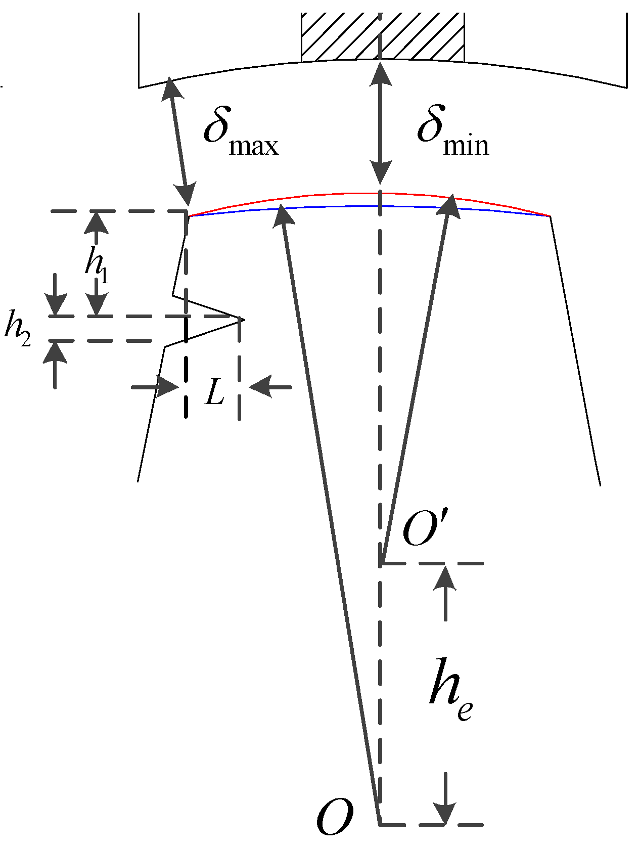
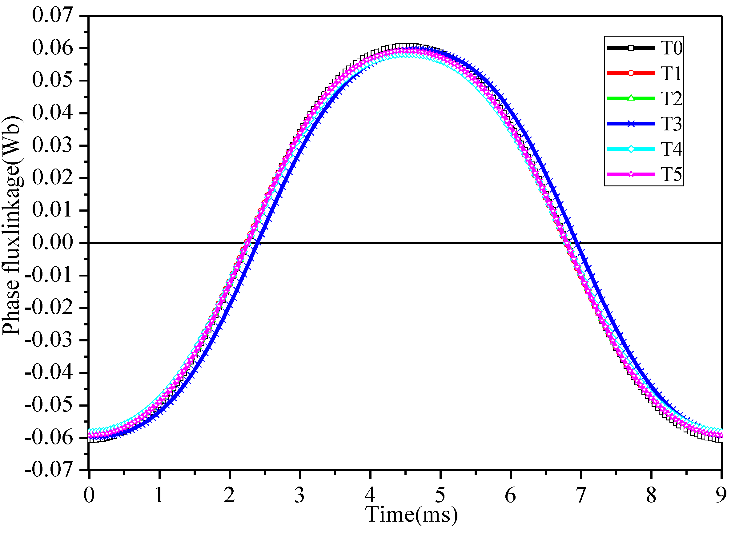
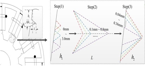
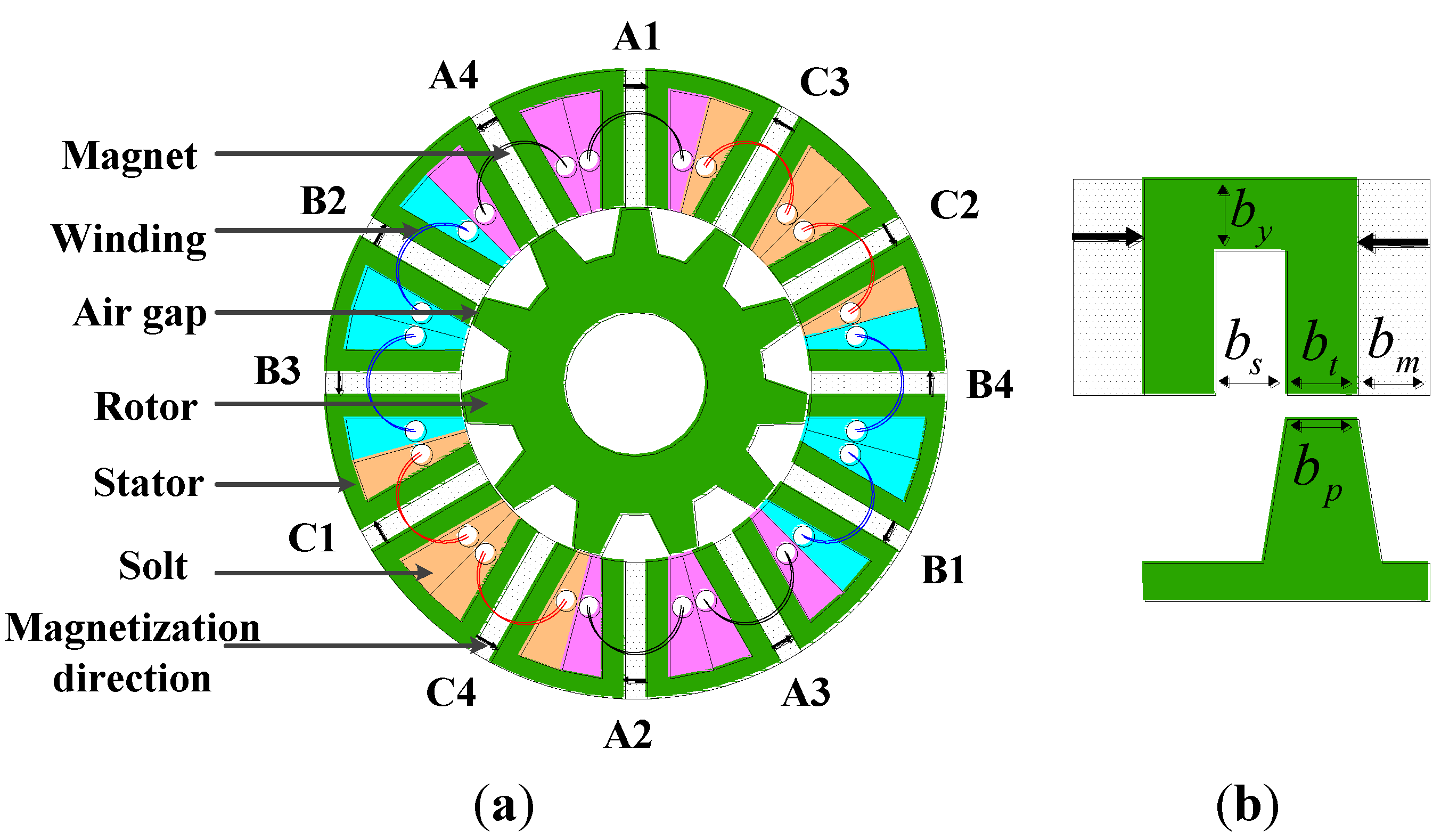
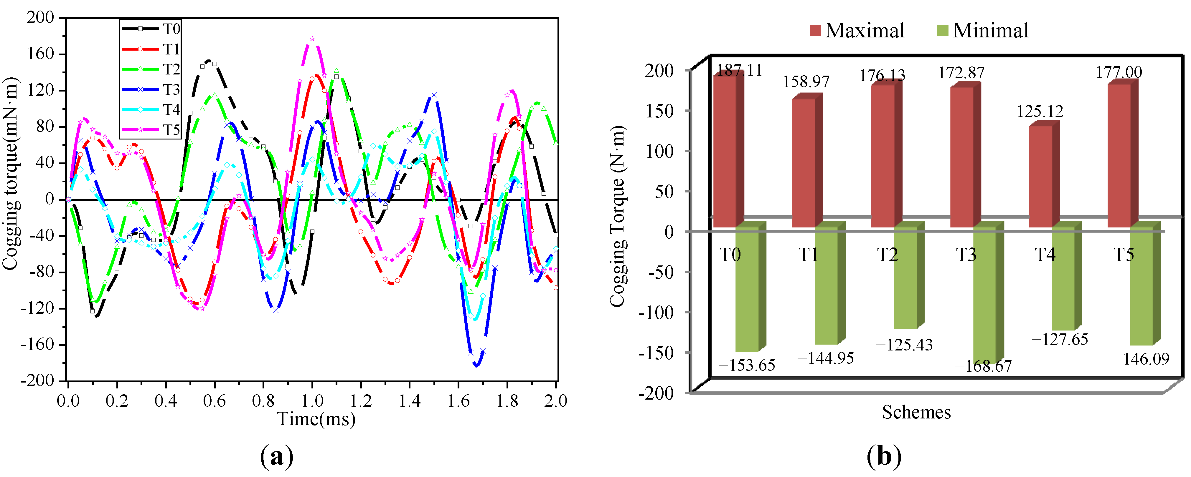
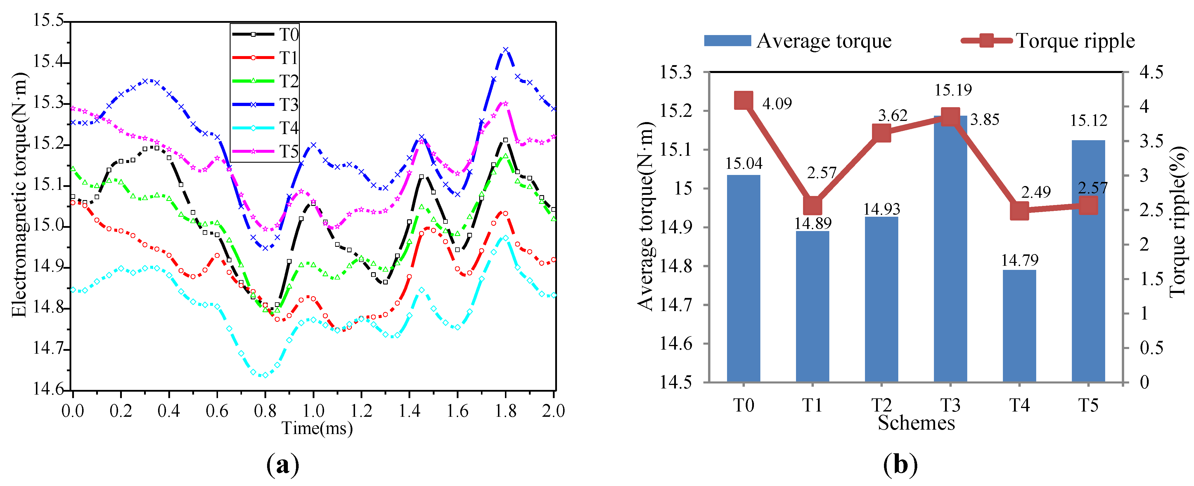
As one of the key part of the EV driveline system, a 12-slot/11-pole FSPM machine used for EVs is researched in this paper. Considering the comparatively larger cogging torque and torque ripple caused by the doubly salient structure, five rotor teeth shapes, i.e., rotor with notched teeth, rotor with stepped teeth, rotor with eccentric teeth, rotor with the combination of stepped and notched teeth, rotor with the combination of eccentric and notched teeth, are investigated to improve the torque characteristics. The laws of torque characteristic changes with the variation of the key parameters in different schemes are obtained and analyzed. The performance with different rotor teeth shapes are compared and discussed comprehensively from the aspects of cogging torque, torque ripple, electromagnetic torque, flux linkage, back EMF, and so on. It is found that the rotor with the combination of stepped and notched teeth has the best effectiveness to reduce the cogging torque by 31.87% and torque ripple by 39.15% but with a slight average torque loss of 1.63%. However, these methods all lead to more or less increased manufacturing costa and some of them may lead to considerable acoustic noise, which will be studied in our future work.

Acknowledgments

This work was supported in part by the National Natural Science Foundation of China under Project 51307008, in part by the Key laboratory for Intelligent Control & Decision of Complex Systems of Beijing Institute of Technology, in part by Ph.D. Programs Foundation of Ministry of Education of China under Project 20121101120024, in part by Basic Research Foundation of Beijing Institute of Technology under Grant 20110642015, 20120642013 and 20130642015, and in part by Excellent Young Scholars Research Fund of Beijing Institute of Technology.

Author Contributions

All authors contributed to this work by collaboration. Jing Zhao was the main author of this manuscript. Yashuang Yan assisted in the design of optimization methods to this study. Bin Li and Zhen Chen provided some useful suggestions in the construction of paper. The whole project was supervised by Xiangdong Liu. All authors revised and approved the publication.

Conflicts of Interest

The authors declare no conflict of interest.

References

  1. Fei, W.Z.; Luk, P.C.K.; Miao, D.-M.; Shen, J.-X. Investigation of torque characteristics in a novel permanent magnet flux switching machine with an outer-rotor configuration. IEEE Trans. Magn. 2013, 45, 4656–4659. [Google Scholar]
  2. Fei, W.; Luk, P.C.K.; Shen, J.X.; Wang, Y.; Jin, M. A novel permanent-magnet flux switching machine with an outer-rotor configuration for in-wheel light traction applications. IEEE Trans. Ind. Appl. 2012, 48, 1496–1506. [Google Scholar] [CrossRef] [Green Version]
  3. Ahmad, M.Z.; Sulaiman, E.; Haron, Z.A.; Kosaka, T. Preliminary studies on a new outer-rotor permanent magnet flux switching machine with hybrid excitation flux for direct drive EV applications. In Proceedings of the 2012 IEEE International Conference on Power and Energy (PECon), Kota Kinabalu, Malaysia, 2–5 December 2012; pp. 928–933.
  4. Hwang, C.-C.; Chang, C.-M.; Hung, S.-S.; Liu, C.-T. Design of high performance flux switching PM machines with concentrated windings. IEEE Trans. Magn. 2014, 50. [Google Scholar] [CrossRef]
  5. Xue, X.; Zhao, W.; Zhu, J.; Liu, G.; Zhu, X.; Cheng, M. Design of five phase modular flux switching permanent magnet machines for high reliability applications. IEEE Trans. Magn. 2013, 49, 3941–3944. [Google Scholar] [CrossRef]
  6. Abdollahi, S.E.; Vaez-Zadeh, S. Back EMF analysis of a novel linear flux switching motor with segmented secondary. IEEE Trans. Magn. 2014, 50, 1–9. [Google Scholar]
  7. Zulu, A.; Mecrow, B.C.; Armstrong, M. Permanent-magnet flux-switching synchronous motor employing a segmental rotor. IEEE Trans. Ind. Appl. 2012, 48, 2259–2267. [Google Scholar] [CrossRef]
  8. Thomas, A.S.; Zhu, Z.Q.; Owen, R.L.; Jewell, G.W.; Howe, D. Multiphase flux-switching permanent-magnet brushless machine for aerospace application. IEEE Trans. Ind. Appl. 2009, 45, 1971–1981. [Google Scholar] [CrossRef]
  9. Thomas, A.S.; Zhu, Z.Q.; Jewell, G.W. Proximity loss study in high speed flux-switching permanent magnet machine. IEEE Trans. Magn. 2009, 45, 4748–4751. [Google Scholar] [CrossRef]
  10. Sulaiman, E.; Kosaka, T.; Matsui, N. Parameter optimization study and performance analysis of 6S-8P permanent magnet flux switching machine with field excitation for high speed hybrid electric vehicles. In Proceedings of the 2011-14th European Conference on Power Electronics and Applications (EPE 2011), Birmingham, UK, 30 August–1 September 2011; pp. 1–9.
  11. Hua, W.; Cheng, M.; Zhang, G. A novel hybrid excitation flux-switching motor for hybrid vehicles. IEEE Trans. Magn. 2009, 45, 4728–4731. [Google Scholar] [CrossRef]
  12. Wang, Y.; Sun, J.; Zou, Z.; Wang, Z.; Chau, K.T. Design and analysis of a HTS flux-switching machine for wind energy conversion. IEEE Trans. Appl. Supercond. 2013, 23. [Google Scholar] [CrossRef]
  13. Zhang, G.; Cheng, M.; Hua, W.; Dong, J. Analysis of the oversaturated effect in hybrid excited flux-switching machines. IEEE Trans. Ind. Magn. 2011, 47, 2827–2830. [Google Scholar] [CrossRef]
  14. Raminosoa, T.; Gerada, C.; Galea, M. Design considerations for a fault-tolerant flux-switching permanent-magnet machine. IEEE Trans. Ind. Electron. 2011, 58, 2818–2825. [Google Scholar] [CrossRef]
  15. Li, G.; Ojeda, J.; Hoang, E.; Gabsi, M. Double and single layers fault-tolerant flux-switching permanent-magnet motor: Fault tolerant model for critical applications. In Proceedings of the 2011 International Conference on Electrical Machines and Systems (ICEMS), Beijing, China, 20–23 August 2011.
  16. Raminosoa, T.; Gerada, C. Fault tolerant winding technology comparison for flux switching machine. In Proceedings of the 2010 XIX International Conference on Electrical Machines (ICEM), Rome, Italy, 6–8 September 2010; pp. 1–6.
  17. Zhao, W.; Cheng, M.; Chau, K.T.; Hua, W.; Jia, H.; Ji, J.; Li, W. Stator-flux-oriented fault-tolerant control of flux-switching permanent-magnet motors. IEEE Trans. Magn. 2011, 47, 4191–4194. [Google Scholar] [CrossRef] [Green Version]
  18. Chen, J.T.; Zhu, Z.Q. Winding configurations and optimal stator and rotor pole combination of flux-switching PM brushless AC machines. IEEE Trans. Energy Convers. 2010, 25, 293–302. [Google Scholar] [CrossRef]
  19. Chen, J.T.; Zhu, Z.Q. Comparison of all- and alternate-poles-wound flux-switching PM machines having different stator and rotor pole numbers. IEEE Trans. Ind. Appl. 2010, 46, 1406–1415. [Google Scholar] [CrossRef]
  20. Zheng, P.; Zhao, J.; Han, J.; Wang, J.; Yao, Z.; Liu, R. Optimization of the magnetic pole shape of a permanent-magnet synchronous motor. IEEE Trans. Magn. 2007, 43, 2531–2533. [Google Scholar] [CrossRef]
  21. Zhao, W.; Lipo, T.A.; Kwon, B. Material-efficient permanent-magnet shape for torque pulsation minimization in SPM motors for automotive applications. IEEE Trans. Ind. Electron. 2014, 61, 5779–5787. [Google Scholar] [CrossRef]
  22. Fei, W.; Luk, P.C.K.; Shen, J. Torque analysis of permanent-magnet flux switching machines with rotor step skewing. IEEE Trans. Magn. 2012, 48, 2664–2673. [Google Scholar] [CrossRef] [Green Version]
  23. Fei, W.; Luk, P.C.K.; Shen, J.X.; Xia, B.; Wang, Y. Permanent-magnet flux-switching integrated starter generator with different rotor configurations for cogging torque and torque ripple mitigations. IEEE Trans. Ind. Appl. 2011, 47, 1247–1256. [Google Scholar] [CrossRef] [Green Version]
  24. Wang, D.; Wang, X.; Jung, S.-Y. Reduction on cogging torque in flux-switching permanent magnet machine by teeth notching schemes. IEEE Trans. Magn. 2012, 48, 4228–4231. [Google Scholar] [CrossRef]
  25. Abdollahi, S.E.; Vaez-Zadeh, S. Reducing cogging torque in flux switching motors with segmented rotor. IEEE Trans. Magn. 2013, 49, 5304–5309. [Google Scholar] [CrossRef]
  26. Zhu, Z.Q.; Chen, J.T.; Pang, Y.; Howe, D.; Iwasaki, S.; Deodhar, R. Analysis of a novel multi-tooth flux-switching PM brushless AC machine for high torque direct-drive applications. IEEE Trans. Magn. 2008, 44, 4313–4316. [Google Scholar] [CrossRef]
  27. Cai, J.; Lu, Q.; Jin, Y.; Chen, C.; Ye, Y. Performance investigation of multi-tooth flux-switching PM linear motor. In Proceedings of the 2011 International Conference on Electrical Machines and Systems (ICEMS), Beijing, China, 20–23 August 2011.
  28. Xu, W.; Lei, G.; Wang, T.; Yu, X.; Zhu, J.; Guo, Y. Theoretical research on new laminated structure flux switching permanent magnet machine for novel topologic plug-in hybrid electrical vehicle. IEEE Trans. Magn. 2012, 48, 4050–4053. [Google Scholar] [CrossRef]
  29. Zhao, W.; Cheng, M.; Chau, K.T.; Cao, R.; Ji, J. Remedial injected-harmonic-current operation of redundant flux-switching permanent-magnet motor drives. IEEE Trans. Ind. Electron. 2013, 60, 151–159. [Google Scholar] [CrossRef] [Green Version]
  30. Zhao, W.; Cheng, M.; Hua, W.; Jia, H.; Cao, R. Back-EMF harmonic analysis and fault-tolerant control of flux-switching permanent-magnet machine with redundancy. IEEE Trans. Ind. Electron. 2011, 58, 1926–1935. [Google Scholar] [CrossRef]
  31. Zhao, W.; Cheng, M.; Cao, R.; Ji, J. Experimental comparison of remedial single-channel operations for redundant flux-switching permanent magnet motor drive. Prog. Electromagn. Res. 2012, 123, 189–204. [Google Scholar] [CrossRef]

