2.1. Voltage Drop Problem in a Radial DC Microgrid System
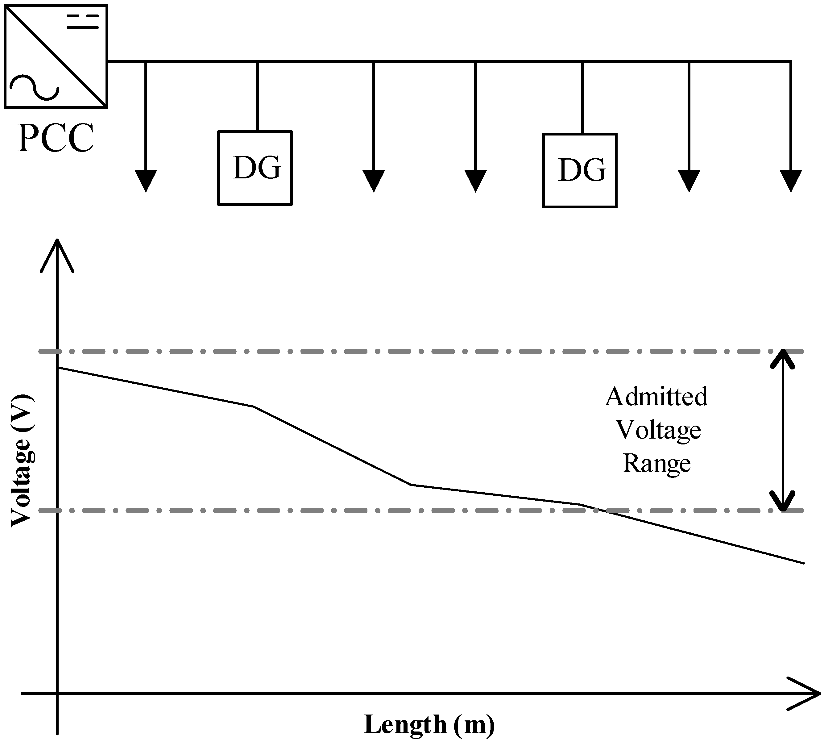
In a typical DC microgrid with a radial topology, power flows from its point of common coupling (PCC) to the end bus in one direction. Therefore, a voltage drop problem can occur with a line voltage drop and the lowest bus voltage is formed at the receiving end in the system. The value of the line voltage drop increases in proportion to the load current magnitude and the line length in the microgrid.
Figure 1 shows a typical voltage profile in a DC microgrid. In this instance, some bus voltages, normally at the end of a system, are out of the admitted voltage range as the distribution line becomes longer. Moreover, certain sensitive loads without a voltage compensator could malfunction and the voltage stability might deteriorate further as the bus voltages become seriously diminished. Therefore, a voltage control method is needed to maintain the system bus voltage within an appropriate range.
Figure 1.
Voltage profile in a DC microgrid.
Figure 1.
Voltage profile in a DC microgrid.
In recent studies regarding system voltage control in a DC microgrid, the main focus was on how to control a DG and energy storage device to maintain only one bus voltage within the required range. However, the controlled target bus voltage should be extended to all bus voltages as the system is expanded. This requires a new control scheme different from the previous method used in a small scale DC microgrid, and the new control scheme should guarantee that voltages at all buses are maintained within the appropriate voltage range.
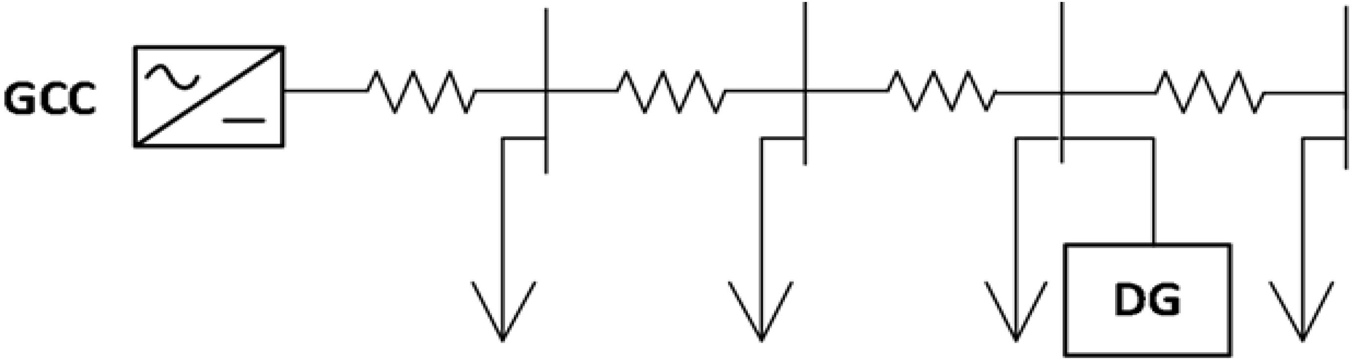
2.2. Cooperative Voltage Control Scheme with a Grid Connected Converter and a Distributed Generation
In an AC power system, a variety of devices, such as shunt capacitors, shunt reactors, transformers, static VAR compensators (SVC), STATCOMs, are used to control system voltages because the voltages are influenced considerably by reactive power. However, there is no reactive power in a DC system, and system voltages are determined by active power-flow. Therefore, a different scheme from an AC system is needed to regulate system voltages in a DC system.
In this paper, a grid-connected converter and a controllable distributed generator, which includes an energy storage device, are used for the cooperative voltage control in a DC microgrid as shown in
Figure 2. Advantages of each device could be emphasized through the cooperative voltage control because the devices have opposite characteristics.
Figure 2.
The proposed voltage control topology in a radial DC microgrid.
Figure 2.
The proposed voltage control topology in a radial DC microgrid.
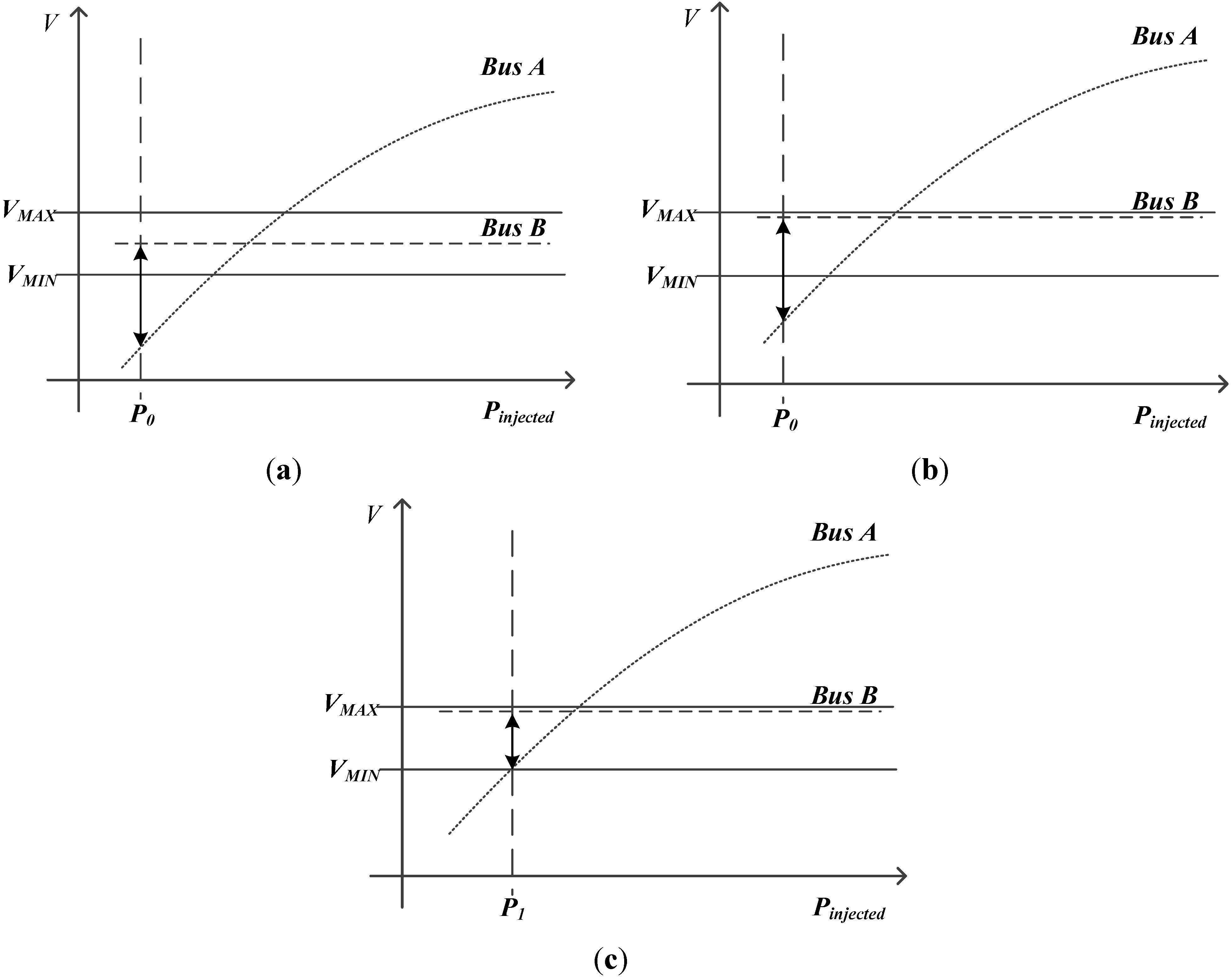
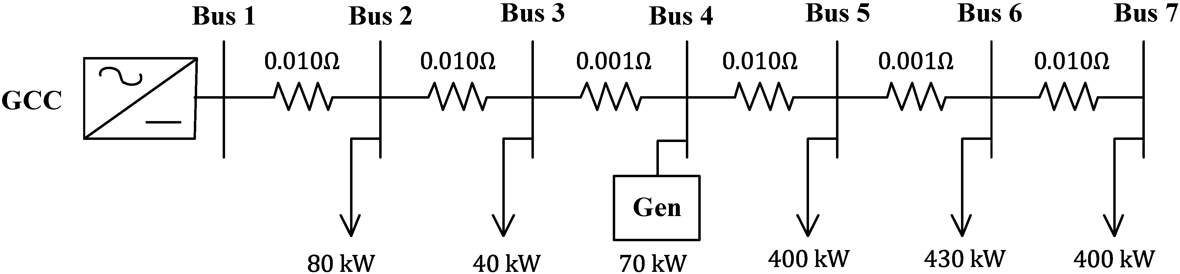
A Grid-Connected Converter (GCC) acts as an on-load tap-changing transformer in an AC power system from a voltage control point of view, and it can efficiently control all system voltages at the secondary side of the converter by a PWM switching operation. The converter is located at the PCC in the proposed control scheme to control the voltages at all buses in a DC microgrid. Therefore, the GCC is used for voltage control at the PCC only, and an additional series converter is not considered in this paper. Furthermore, the line voltage drop increases with load current, especially at a low bus voltage, which causes a large voltage difference between some buses in a radial DC microgrid. In the case where a large voltage difference exists between some buses and only the GCC controls the system voltages, maintaining all system voltages in the admitted range can be a problem. This problem cannot be solved with the GCC only, because voltage control of the GCC is performed either by increasing or decreasing system voltages.
A DG is a good solution for the problem mentioned previously. A DG can control system voltages locally in a radial DC microgrid because all the buses in the system have quite different voltage sensitivities with respect to the injected power from the DG. In particular, a controllable DG with the capability of charging or discharging, such as an energy storage device, can solve the over voltage problem and under voltage problem as well. However, the overall over voltage or under voltage problems in the entire system cannot be solved if only a DG is used for voltage control. In addition, the generation costs of the DG should be an essential concern for economical control operations because the voltage control with the DG is performed by power in a DC microgrid.
Voltage control in all power systems, including a DC microgrid, is closely related to voltage sensitivities. Similar to an AC system, a bus with high voltage sensitivity usually has low voltage and a bus with low voltage sensitivity has high voltage in a DC microgrid. Because a relatively large amount of power is required to control the voltage at a bus with low voltage sensitivity, a GCC should control the voltage at a bus with the lowest voltage sensitivity. Furthermore, voltage sensitivities in a DC microgrid should be considered to maintain system voltages, especially with voltage control with a DG. This is because a small amount of power is needed for voltage control and a DG usually has limits of current and generation capacity. Therefore, the voltage at a bus with high voltage sensitivity should be controlled by a DG.
Based on the aforementioned fact, a cooperative voltage control method is proposed as follows:
- -
A GCC controls the voltage of a bus with the lowest voltage sensitivity in a DC microgrid. A bus with a higher voltage normally has lower voltage sensitivity. Therefore, a large generating power is needed if a bus voltage is controlled by a DG. Therefore, a GCC is suitable for this bus from an economic perspective.
- -
A DG regulates the lowest bus voltage in a DC microgrid so that the voltage can be controlled with the minimum capacity of the DG. A bus with lower voltage has higher voltage sensitivity, and the voltage can be regulated effectively with a small generated power delivered from a DG.
- -
A GCC should control its target bus voltage as high as possible to reduce line loss. In addition, this leads to a decrease in the power delivered from a DG because the amount of line voltage drop decreases with high voltage.
Consequently, both overall over voltage and under voltage problems are controlled by a GCC, and a local voltage problem can be solved by a DG. Furthermore, the proposed scheme can reduce the operation cost for voltage control from a long term perspective because the power delivered from a DG can be reduced and the overall voltage can be regulated.


