Voltage Control Scheme with Distributed Generation and Grid Connected Converter in a DC Microgrid


Abstract
:1. Introduction
2. Cooperative Voltage Control Scheme in a DC Microgrid
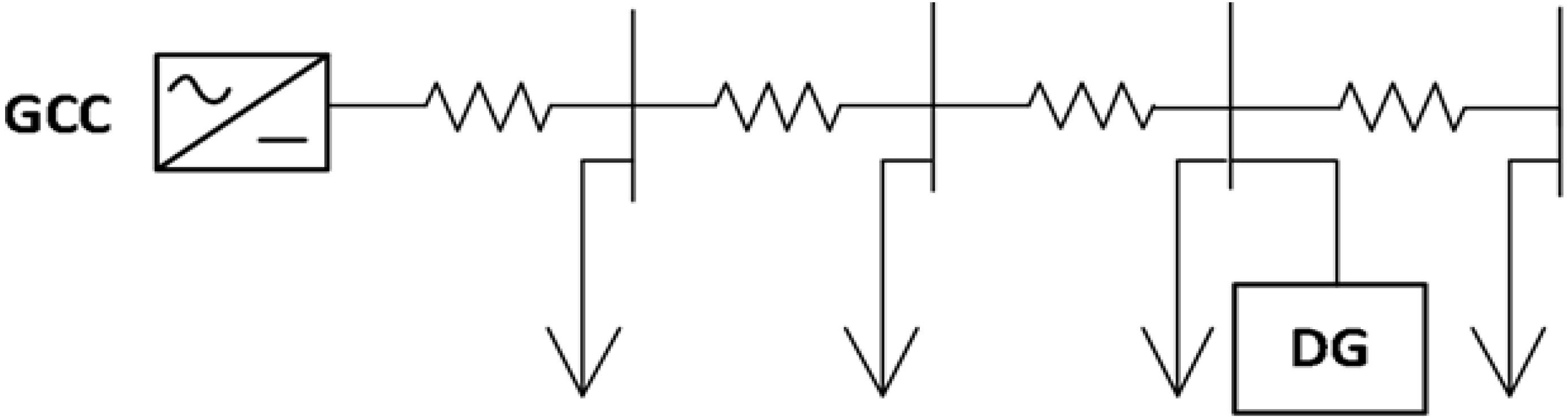
2.1. Voltage Drop Problem in a Radial DC Microgrid System
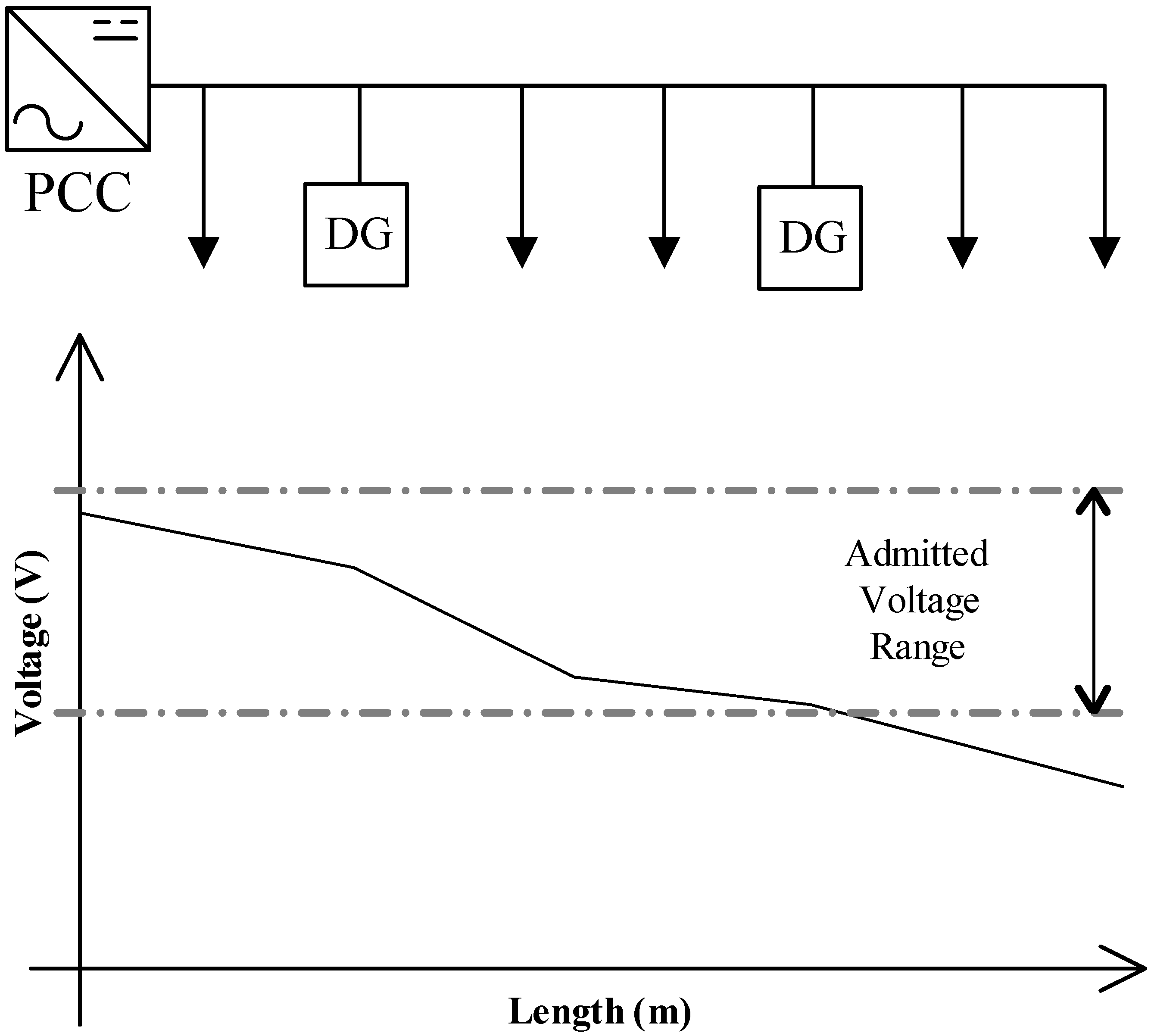
2.2. Cooperative Voltage Control Scheme with a Grid Connected Converter and a Distributed Generation

- -
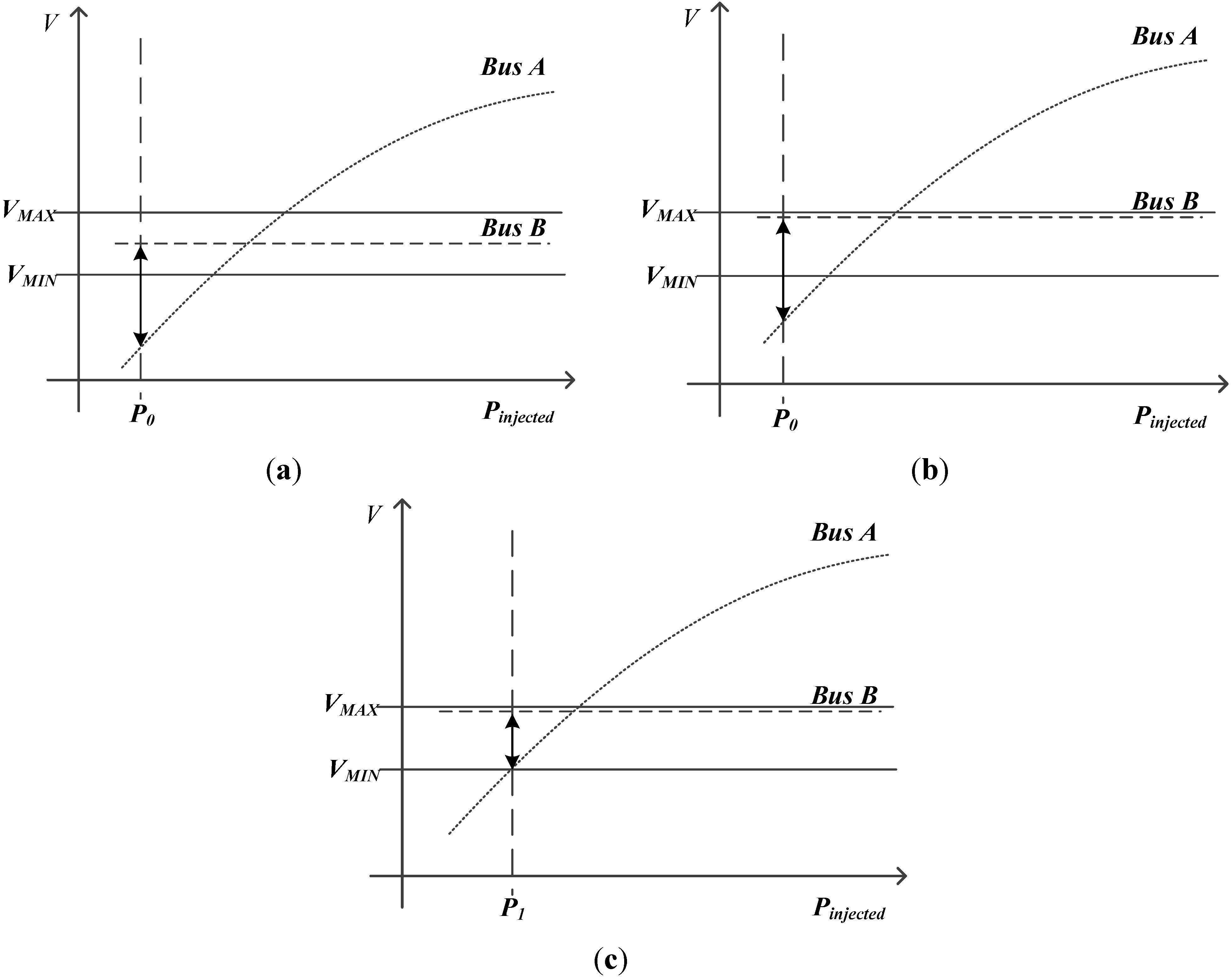
- A GCC controls the voltage of a bus with the lowest voltage sensitivity in a DC microgrid. A bus with a higher voltage normally has lower voltage sensitivity. Therefore, a large generating power is needed if a bus voltage is controlled by a DG. Therefore, a GCC is suitable for this bus from an economic perspective.
- -
- A DG regulates the lowest bus voltage in a DC microgrid so that the voltage can be controlled with the minimum capacity of the DG. A bus with lower voltage has higher voltage sensitivity, and the voltage can be regulated effectively with a small generated power delivered from a DG.
- -
- A GCC should control its target bus voltage as high as possible to reduce line loss. In addition, this leads to a decrease in the power delivered from a DG because the amount of line voltage drop decreases with high voltage.
3. Optimal DG Allocation Algorithm

- ∆P = incremental change in bus active power injection;
- ∆Q = incremental change in bus reactive power injection;
- ∆θ = incremental change in bus voltage angle;
- ∆V = incremental change in bus voltage magnitude.


| Abbreviation | Definition |
|---|---|
| Bus H | Bus with the highest voltage in the DC microgrid |
| Bus L | Bus with the lowest voltage in the DC microgrid |
| Bus I | Bus with the highest voltage sensitivity affected by injected power into Bus L |
| VHigh | Voltage at bus H |
| VLow | Voltage at bus L |
| VMax | Maximum voltage limit in the DC microgrid |
| VMin | Minimum voltage limit in the DC microgrid |
| NGCC | Ratio of voltage at the secondary side of GCC on rated voltage of the system |
- -
- Solve the power-flow calculation for the DC system and choose Bus H and Bus L.
- -
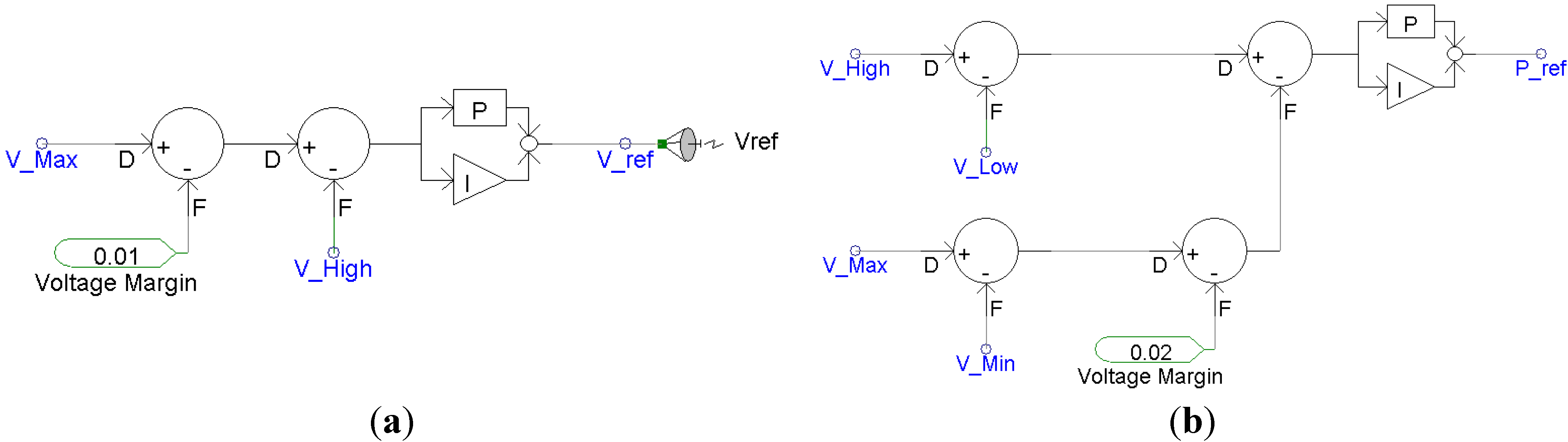
- Check the voltage violation condition to identify need of a battery as follows:|VHigh − VLow| > VMax − VMin
- -
- Check Bus I, and add Bus I to the list as a candidate for optimal DG allocation.
- -
- A battery is not required if Equation (8) is not satisfied.
- -
- Change NGCC step size until the voltage at Bus H exceeds VMax.
- -
- Check the voltage violation condition to identify need of a battery as follows.
- -
- A battery is not required if Equation (8) is not satisfied.
- -
- Check Bus I and add to the list if Bus I is changed.
- -
- Change the power at Bus I as Equation (9), and repeat this procedure until PI becomes smaller than the tolerance value.
![Energies 07 06477 i006]()
- -
- If Equation (8) is satisfied, check Bus I and add to the list if Bus I is changed.

- -
- Repeat steps 2 and 3 until the voltages at all buses are within the admitted range.
- -
- In this step, the minimum capacity of the battery is determined when the battery is located at Bus I.
- -
- Repeat steps 1 to 4 if new buses are added to the list of bus I through steps 1 to 4.
- -
- Compare the required capacity of the battery according to the location of the battery. The bus where the required capacity of the battery is the smallest is the optimal location.
4. Cooperative Voltage Control Method
5. Case Studies
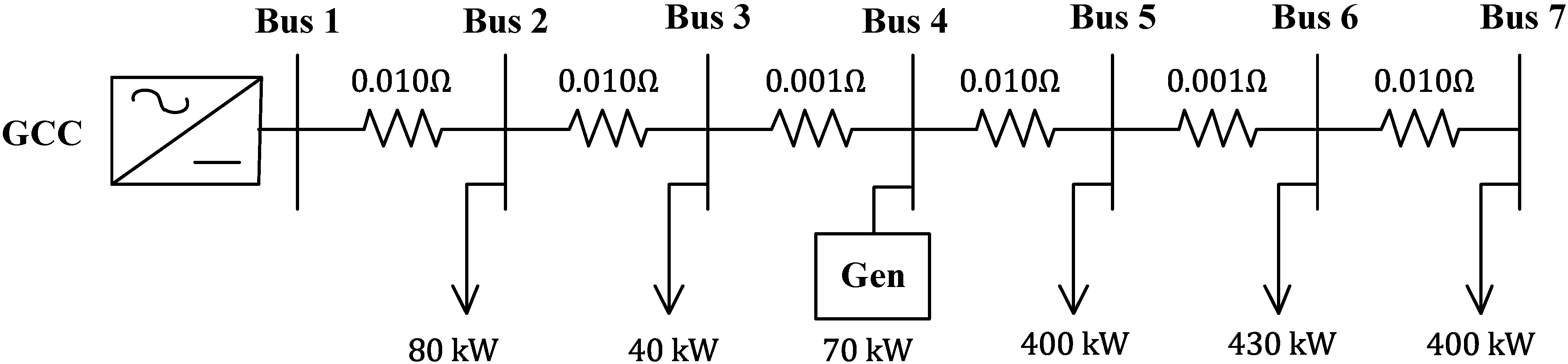
5.1. Verification of the Optimal DG Allocation Algorithm

| Bus Number | Bus Number | Line Resistance (Ω) |
|---|---|---|
| 1 | 2 | 0.010 |
| 2 | 3 | 0.010 |
| 3 | 4 | 0.001 |
| 4 | 5 | 0.010 |
| 5 | 6 | 0.001 |
| 6 | 7 | 0.010 |
| Bus Number | Generation Power (kW) | Load Power (kW) | Bus Voltage (pu) |
|---|---|---|---|
| 1 | 7867 | - | 1.122 |
| 2 | - | 80 | 1.050 |
| 3 | - | 40 | 0.986 |
| 4 | - | −70 (Gen) | 0.983 |
| 5 | 1445 | 400 | 0.951 |
| 6 | - | 430 | 0.950 |
| 7 | - | 400 | 0.992 |
| Bus Number | Generation Power (kW) | Load Power (kW) | Bus Voltage (pu) |
|---|---|---|---|
| 1 | 7867 | - | 1.123 |
| 2 | - | 80 | 1.050 |
| 3 | - | 40 | 0.985 |
| 4 | - | −70 (Gen) | 0.983 |
| 5 | - | 400 | 0.950 |
| 6 | 1425 | 430 | 0.951 |
| 7 | - | 400 | 0.993 |
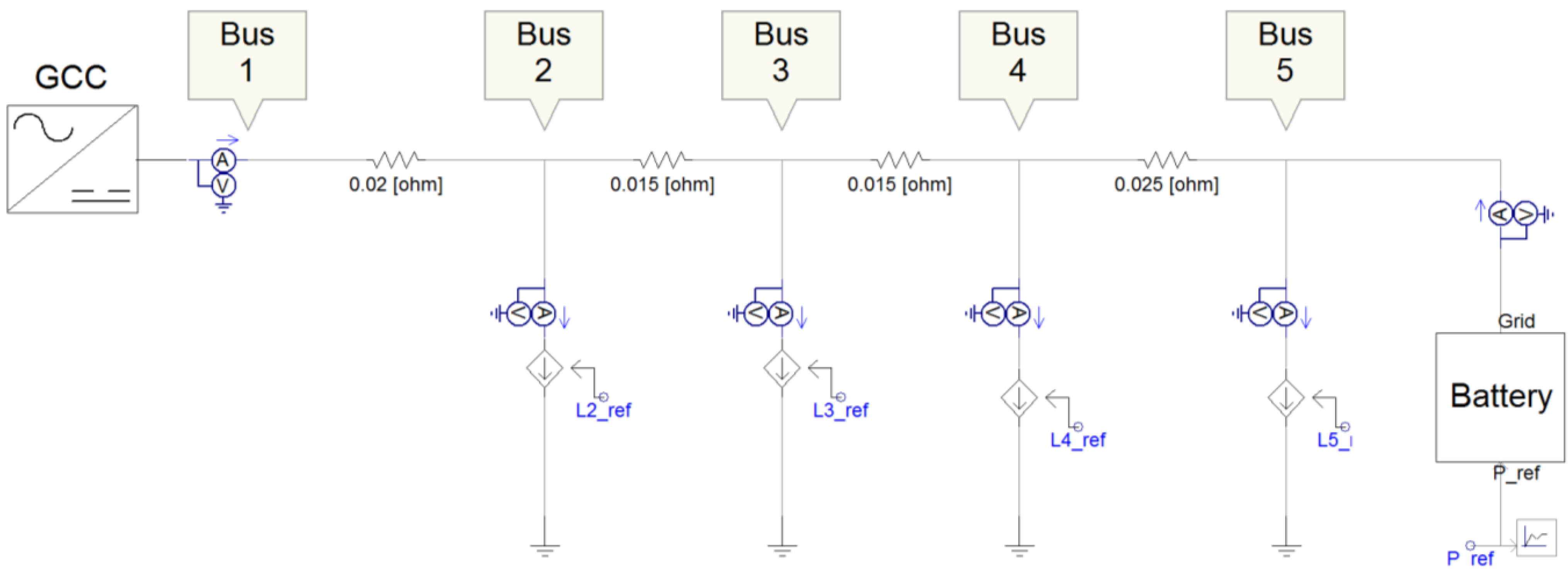
5.2. Verification of the Cooperative Voltage Control Method

| Time | Load Power (kW) | Voltage Control | ||||
|---|---|---|---|---|---|---|
| Bus 2 | Bus 3 | Bus 4 | Bus 5 | GCC | Battery | |
| 0 s | --------------- Initializing --------------- | |||||
| 1 s | 10 | 20 | 20 | 10 | X | X |
| 2 s | 50 | 70 | 70 | 50 | O | X |
| 3 s | 50 | 70 | 70 | 50 | O | X |
| 4 s | 70 | 100 | 100 | 80 | O | X |
| 5 s | 70 | 100 | 100 | 80 | O | O |
| 6 s | 40 | 60 | 70 | 40 | O | O |
- -
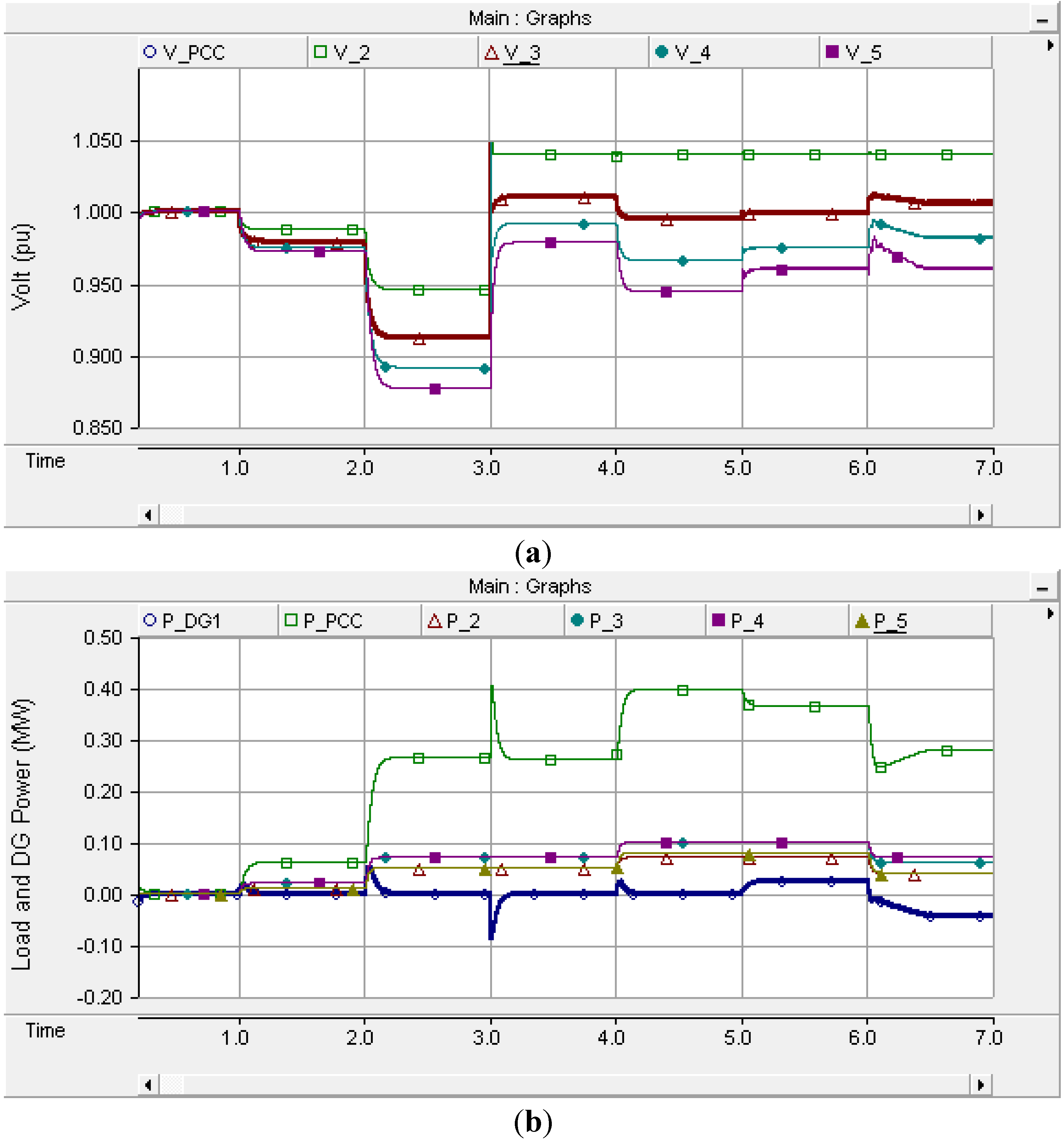
- 0–1 s: The test system is initialized. No load is connected to the grid.
- -
- 1–2 s: The GCC and the battery do not participate in the proposed voltage control. The voltage at the secondary side of the GCC is fixed to 1.0 pu by the GCC and the power delivered from the battery is zero. The bus voltages are in the required voltage range because the overall load consumption power is low.
- -
- 2–3 s: The overall load increases, and a voltage violation occurs because the voltages of buses 3 and 4 deviate from the required range.
- -
- 3–4 s: The GCC regulates the bus voltage, which is the highest in the DC microgrid. In this case, the voltage at Bus 2 is regulated at 1.04 pu by the GCC, and all bus voltages remain in the admitted range.
- -
- 4–5 s: The load consumption powers are increased further, and the voltage at Bus 5 falls to 0.944 pu. Although the bus voltages are controlled by the GCC, some bus voltages are out of the admitted range.
- -
- 5–6 s: The GCC participates continuously in the proposed voltage control and the battery starts controlling the local voltage. Power is delivered from the battery at Bus 5 to boost the voltage that is under the minimum voltage limit. As a result, all bus voltages are within the normal range.
- -
- 6–7 s: The GCC and battery still participates in the proposed cooperative voltage control. The power consumption of some loads is decreased. Therefore, the power delivered from the battery might not be essential to regulate the bus voltages. This makes the battery change modes from discharging to charging. However, if an uncontrolled generator, such as a renewable energy source, produces a large amount of output, the role of the battery is vital in controlling the voltage. In this case, the bus voltages could be regulated, even though the battery is charged. Therefore, in this case, the charging power is consumed by a battery to recover the state of charge (SOC) of the battery.
| Time | Bus Voltage (pu) | Voltage Control | Voltage Violations | ||||
|---|---|---|---|---|---|---|---|
| Bus 2 | Bus 3 | Bus 4 | Bus 5 | GCC | DG | ||
| 0 s | --------------- Initializing --------------- | ||||||
| 1 s | 1.0 | 0.979 | 0.974 | 0.971 | X | X | X |
| 2 s | 0.945 | 0.912 | 0.891 | 0.876 | X | X | O |
| 3 s | 1.04 | 1.01 | 0.991 | 0.978 | O | X | X |
| 4 s | 1.04 | 0.995 | 0.966 | 0.944 | O | X | O |
| 5 s | 1.04 | 0.999 | 0.975 | 0.960 | O | O | X |
| 6 s | 1.04 | 1.006 | 0.982 | 0.959 | O | O | X |
6. Conclusions
Acknowledgments
Author Contributions
Conflicts of Interest
References
- Kaipia, T.; Salonen, P.; Lassila, J.; Partanen, J. Possibilities of the low voltage DC distribution systems. In Proceedings of the NORDAC 2006 Conference, Stockholm, Sweden, 10 August 2006.
- Donald, H.J. AC Versus DC distribution systems–did we get it right? In Proceedings of the Power Engineering Society General Meeting, Tampa, FL, USA, 24–28 June 2007.
- Sannino, A.; Postiglione, G.; Bollen, M.H.J. Feasibility of a DC network for commercial facilities. IEEE Trans. Ind. Appl. 2003, 5, 1499–1507. [Google Scholar] [CrossRef]
- Kakigano, H.; Miura, Y.; Ise, T.; Uchida, R. DC voltage control of the DC micro-grid for super high quality distribution. In Proceedings of the Power Conversion Conference, Nagoya, Japan, 2–7 April 2007.
- Wu, T.-F.; Chang, C.-H.; Lin, L.-C.; Yu, G.-R.; Chang, Y.-R. DC-bus voltage control with a three-phase bidirectional inverter for DC distribution systems. In Proceedings of the IEEE Transactions on Power Electronics, Orlando, FL, USA, 5–9 February 2013; Volume 4, pp. 1890–1899.
- Wu, T.-F.; Kuo, C.-L.; Sun, K.-H.; Yu, G.-R. DC-bus voltage regulation with bi-directional inverter in DC distribution systems. In Proceedings of the Applied Power Electronics Conference and Exposition (APEC),2012 Twenty-Seventh Annual IEEE, Orlando, FL, USA, 5–9 February 2012; pp. 769–774.
- Akbari, M.; Golkar, M.A.; Tafreshi, S.M.M. Voltage control of a hybrid ac/dc microgrid in grid-connected operation mode. In Proceedings of the 2011 IEEE PES on Innovative Smart Grid Technologies-India (ISGT India), Kollam, Kerala, India, 1–3 December 2011.
- Lazaroiu, G.C.; Popescu, M.O.; Dumbrava, V.; Stroe, C. Voltage control system and transient analysis of DG interfaced dc distribution system. In Proceedings of the Renewable Power Generation (RPG 2011), IET Conference on, Edinburgh, Scotland, UK, 6–8 September 2011.
- Ito, Y.; Zhongqing, Y.; Akagi, H. DC microgrid based distribution power generation system. In Proceedings of the Power Electronics and Motion Control Conference, 2004, Xi’an, China, 14–16 August 2004.
- Kakigano, H.; Nishino, A.; Ise, T. Distribution voltage control for DC microgrid with fuzzy control and gain-scheduling control. In Proceedings of the IEEE Power Electronics and ECCE Asia 8th International Conference, Jeju Island, Korea, 30 May–3 June 2011.
- Kundur, P. Power System Stability and Control; McGraw-Hill: New York, NY, USA, 1993; pp. 740–741. [Google Scholar]
© 2014 by the authors; licensee MDPI, Basel, Switzerland. This article is an open access article distributed under the terms and conditions of the Creative Commons Attribution license (http://creativecommons.org/licenses/by/4.0/).
Share and Cite
Choi, J.-C.; Jeong, H.-Y.; Choi, J.-Y.; Won, D.-J.; Ahn, S.-J.; Moon, S.-i. Voltage Control Scheme with Distributed Generation and Grid Connected Converter in a DC Microgrid. Energies 2014, 7, 6477-6491. https://doi.org/10.3390/en7106477
Choi J-C, Jeong H-Y, Choi J-Y, Won D-J, Ahn S-J, Moon S-i. Voltage Control Scheme with Distributed Generation and Grid Connected Converter in a DC Microgrid. Energies. 2014; 7(10):6477-6491. https://doi.org/10.3390/en7106477
Chicago/Turabian StyleChoi, Jong-Chan, Ho-Yong Jeong, Jin-Young Choi, Dong-Jun Won, Seon-Ju Ahn, and Seung-il Moon. 2014. "Voltage Control Scheme with Distributed Generation and Grid Connected Converter in a DC Microgrid" Energies 7, no. 10: 6477-6491. https://doi.org/10.3390/en7106477
APA StyleChoi, J.-C., Jeong, H.-Y., Choi, J.-Y., Won, D.-J., Ahn, S.-J., & Moon, S.-i. (2014). Voltage Control Scheme with Distributed Generation and Grid Connected Converter in a DC Microgrid. Energies, 7(10), 6477-6491. https://doi.org/10.3390/en7106477