Optimum Settings for a Compound Parabolic Concentrator with Wings Providing Increased Duration of Effective Temperature for Solar-Driven Systems: A Case Study for Tokyo

Abstract
: We designed a compound parabolic concentrator (CPC) with wings angled toward the east and west. Normally, solar collectors are straight, facing south, and the effective temperature is only achieved for a short period of time at midday. In the proposed design, the collector is divided into three parts, with the ends angled and tilted at different orientations. The objective was to increase the duration of the effective temperature period by capturing the maximum solar energy in the morning and afternoon without tracking by the collector. A simulation model was developed to evaluate the performance of the proposed CPC. The tilt and bending angles of the CPC wings were optimized for year-round operation in Tokyo, Japan. A 35° tilt for the south-facing central part of the CPC and a 45° tilt for the wings with 50° angles toward the east and west were found to be optimal. Analyses were conducted at these optimum settings with temperatures of 70, 80, and 90 °C as minimum requirements. The effective duration increased by up to 2 h in the winter and up to 2.53 h in the summer using the proposed CPC. The proposed CPC will improve the efficiency of solar-driven systems by providing useful heat for longer periods of time with the same collector length and without the need for tracking.1. Introduction
The use of solar energy as an alternative source of energy for heating and cooling is increasing due to energy crises and the rapid depletion of existing non-renewable resources [1–3]. Solar energy is clean and environmentally friendly and is naturally available in abundance in most parts of the world. There are various systems that use solar thermal energy as a driving force, such as solar cooling systems [4,5], solar water heating [6,7] and solar-assisted cooling and heating systems [8,9]. Each system needs a critical temperature for its operation. In order to obtain the required temperature, flat-plate collectors are commonly used [9–12]. Some attention has also been given to using concentrator collectors [13,14], specifically compound parabolic concentrators (CPCs) [15,16]. CPCs can achieve higher temperatures compared to flat-plate collectors and it has also been reported that CPCs have the ability to produce ice with a solar adsorption ice maker on overcast days [16]. For efficient operation of a system, a consistent supply of the required temperature is important. However, solar energy is not constant throughout the day; it increases as the sun rises higher in the sky in the middle of the day and decreases in the afternoon as the sun lowers its position. Normally, solar collectors are straight, facing south. In this case the required temperature is obtained in the middle of the day. To obtain the required temperature for longer period of time, the solar energy needs to be captured efficiently in the morning and afternoon.
In this study, we designed a CPC collector with wings angled toward the east and west to capture maximum energy in the morning and afternoon without the need for tracking. The objectives of the study were to determine the optimum settings for the tilt and bending angles of the proposed CPC for year-round operation and to evaluate the additional duration of useful temperatures achieved in different seasons of the year.
2. Compound Parabolic Concentrator
A compound parabolic concentrator (CPC) is a non-imaging concentrator that consists of two parabolas and one absorber. The absorber may be flat or tubular; the geometry of the CPC profile depends on the shape of the receiver selected. In the current study, a two-dimensional (2D) CPC with a partially exposed tubular absorber was used. Partially exposed receivers have been reported to be favorable for solar adsorption cooling applications as they have the advantage of heat rejection from the back side during adsorption process and increased adsorbent per unit area [15]. Normally, a CPC does not require tracking and it can accept incoming radiation over a relatively wide range of angles by using multiple reflections [17].
Proposed Design of CPC with Wings
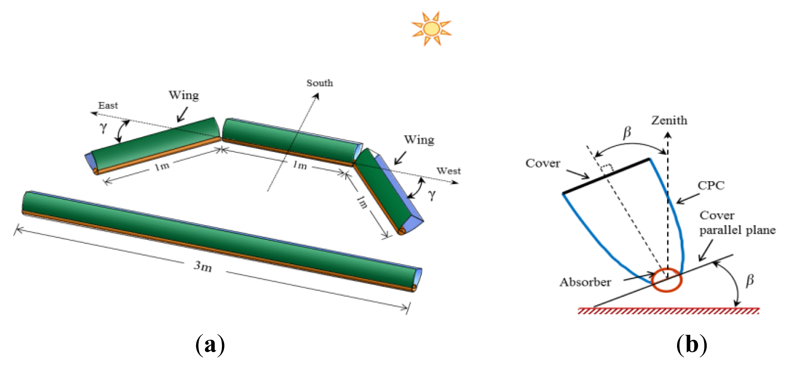
The amount of solar energy collected depends on the orientation of the collector. Ordinary CPC collectors are linear and tilted toward the south (in the Northern Hemisphere) to capture energy in the middle of the day when the sun is radiating maximum energy. In contrast, we propose a new design for a CPC collector with an angled shape (Figure 1).
The length of the proposed CPC is same as for a linear CPC, but is divided into three parts. The ends are termed wings and are angled toward the east and west (surface azimuth angle) to capture maximum solar energy during various times of day. The angled east and west wings with larger tilt angles collect more energy than a linear south-facing CPC in the morning and afternoon, respectively. Thus, the proposed angled CPC can supply the required temperature for longer periods of time than can a conventional linear CPC of the same length and without tracking.
3. Mathematical Models
3.1. Assumptions
A detailed dynamic simulation model was used to predict the temperatures of the CPC cover and receiver based on energy balance equations [18,19]. The following assumptions were made to simplify the model:
The CPC is ideal and free from the fabrication errors.
Each part of the CPC is an independent unit.
Temperature is uniformly distributed on the cover and receiver of the CPC.
There is no heat transfer medium inside the receiver.
The bottom side of the absorber is well-insulated, and there is no heat loss to the surroundings.
3.2. Governing Equations
The CPC cover temperature is given by:
The CPC absorber temperature is given by:
F indicates whether the incident radiation is effective for the CPC. F = 1 if the condition in Eqaution (5) is met and 0 otherwise. The Idiff was calculated by dividing the actual diffuse radiation with the geometric concentration ratio [18]:
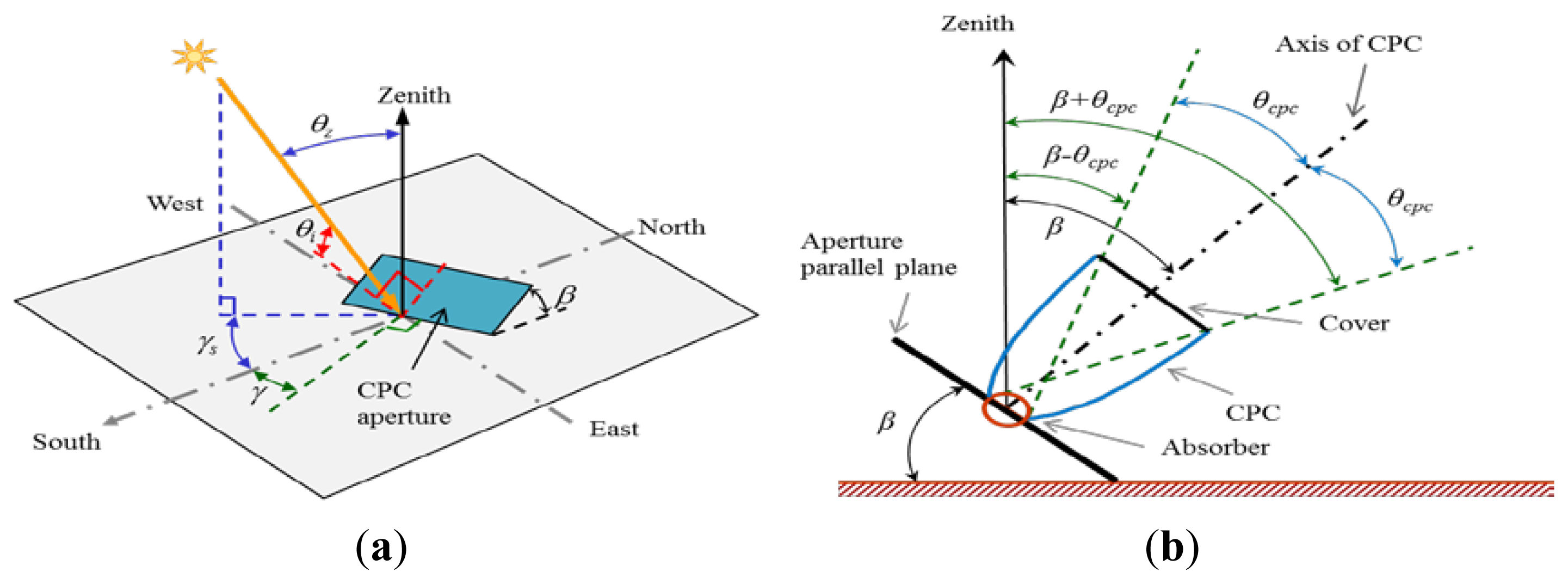
Methods for calculating θi, θz, and γs are given in Appendix A. The explanation of the angles is given in Appendix A, Figure A1. Equations (1) and (3) were used to calculate the temperatures of the cover and absorber of the east, south, and west wings of the CPC using their respective setting parameters. In Equations (1) and (3), the term on the left-hand side is the sensible heat and the terms of the form h·ΔT on the right-hand side are the heat transfers by radiation, convection, and wind from the cover and receiver of the CPC. The equations for calculating hRr, hrc, hRs, and hca are given in Appendix B. The numerical values used in the simulation are given in Table 1.
3.3. Optimization Index
The optimum settings of tilt and bending angles for the wings of the proposed CPC were determined by calculating the sum of the energy absorbed by east wing in the morning until 11:00 and the energy absorbed by the west wing after 13:00, given by:
3.4. Initial Conditions
Initial conditions were as follows:
3.5. Boundary and Operating Conditions
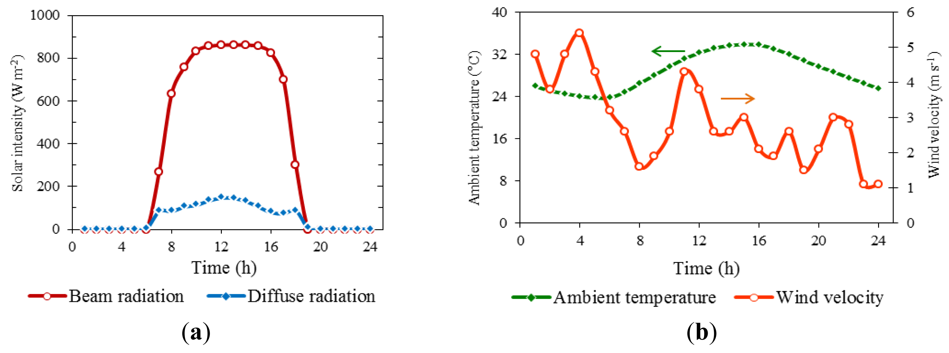
Actual measured data for Tokyo for solar radiation, ambient temperature, and wind velocity were used in the simulation (Figure 2). To evaluate year-round performance, weather data for one sunny day in each month were selected. The data were obtained from the commercial software Meteonorm v. 6.1.
3.6. Numerical Solution of the Mathematical Models
Mathematical models developed for different components of the system were used to compile a computer algorithm with the commercial software MATLAB R2010b. The Ordinary Differential Solver (ode45) tool was used to incorporate the differential equations into the simulation model. Graphs were prepared in Microsoft Excel and SigmaPlot using the simulation results from MATLAB.
4. Results and Discussion
Performance Evaluation of the Proposed CPC with Wings
Determination of Optimum Settings
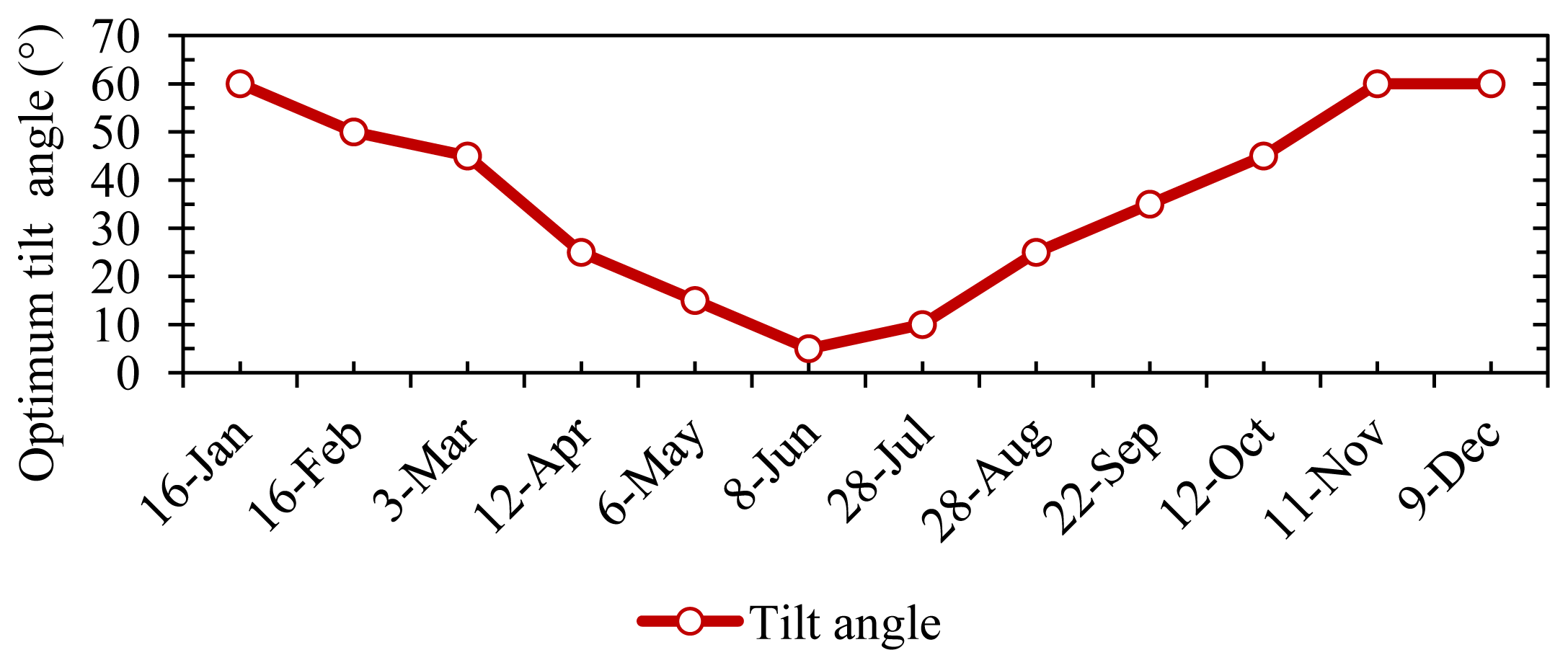
The proposed CPC with wings consists of east, west, and central parts (Figure 1). Initially, the optimum tilt angle for the south-facing central part was determined for year-round operation. The energy absorbed by the tubular receiver of the central part was calculated using Equation (4) at different tilt angles for selected sunny days of each month and the optimum tilt angle was identified. Figure 3 shows the optimum tilt angle for the central part for each month of the year.
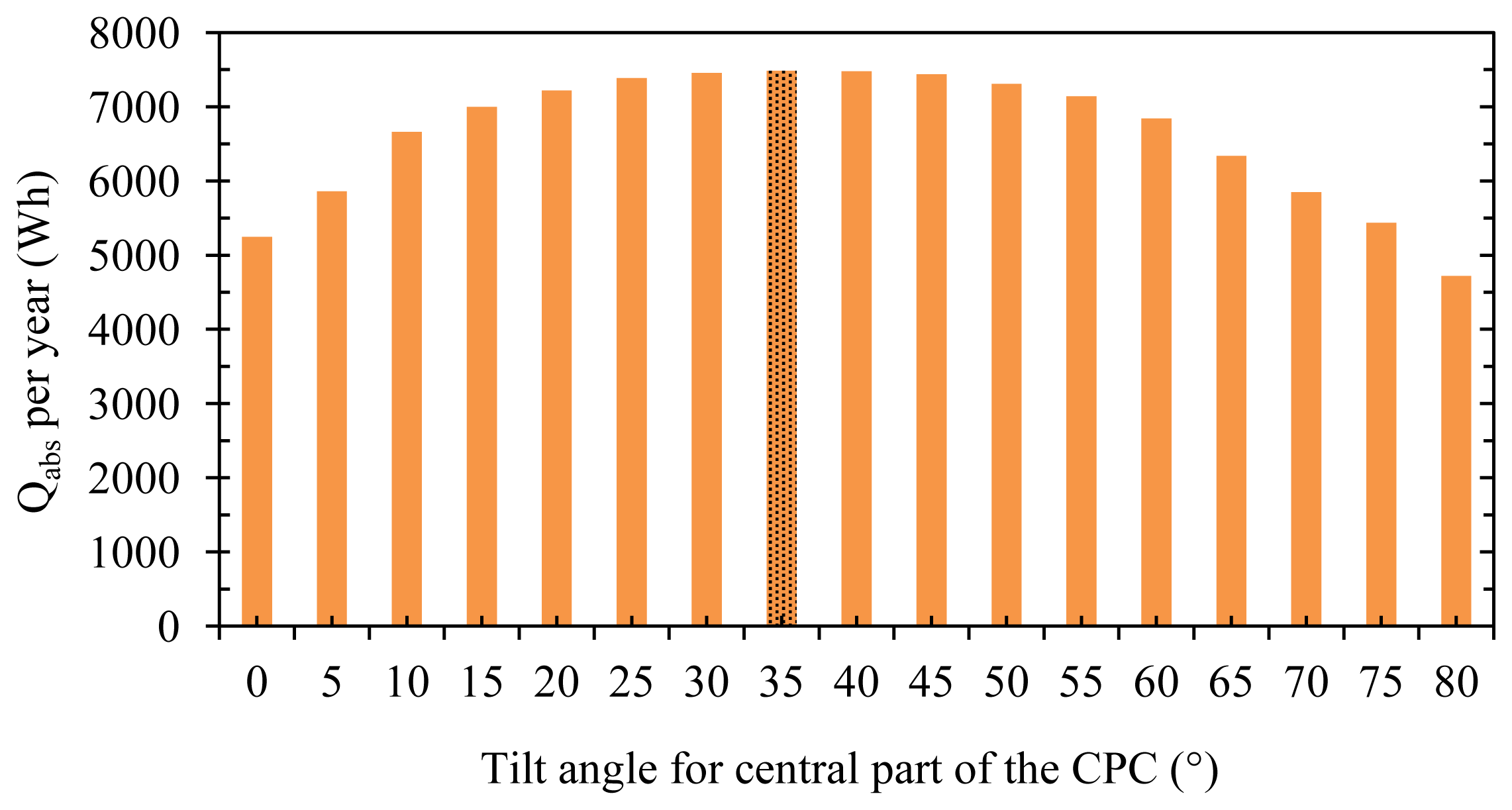
The maximum energy was absorbed using smaller tilt angles in the summer and larger angles in the winter. The year-round optimum fixed tilt angle for the central part of the CPC was found by summing the energies absorbed at each tilt angle in all months; the maximum of the summed energy was absorbed at a tilt angle of 35° (Figure 4). There was not a substantial difference in the absorbed energies among tilt angles of 25°–45°.
Therefore, the optimum tilt setting for the central part can be selected from this range depending on the desired conditions. For example if thermal heat is important in the summer, e.g., for solar cooling systems, a 25° tilt is recommended; if thermal heat is important in the winter, e.g., for solar water or space heating systems, then a 45° tilt is recommended.
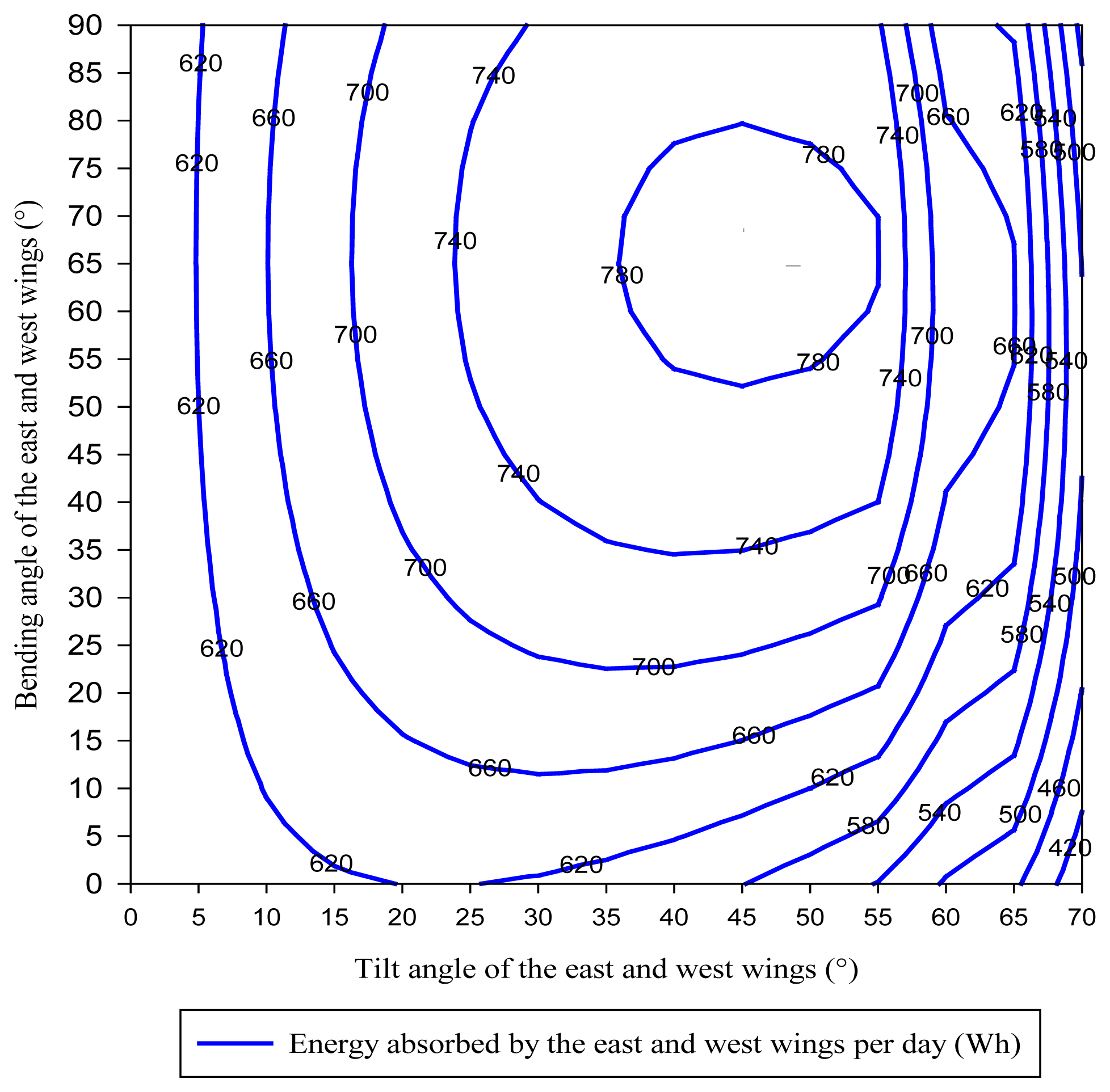
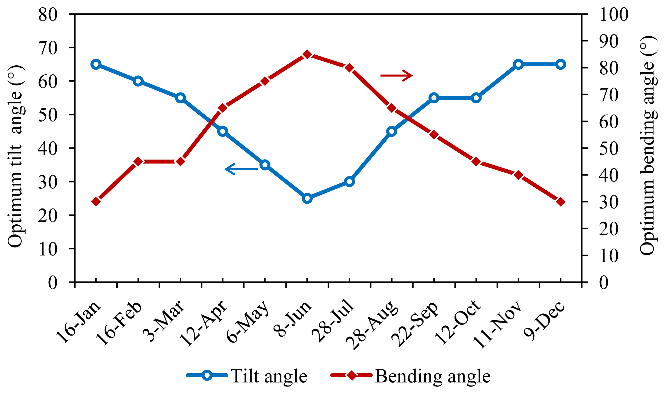
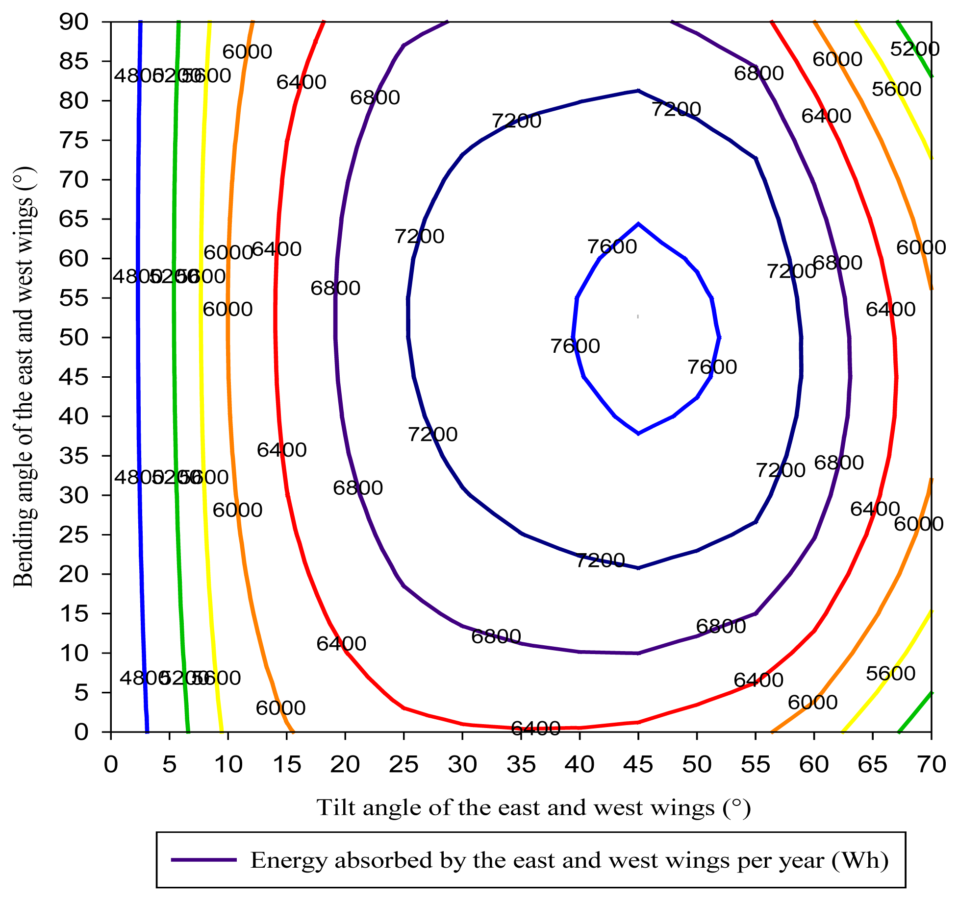
The performance of the proposed CPC with wings was evaluated by calculating the sum of the energy absorbed by the east wing in the morning until 11:00 and the energy absorbed by the west wings in the afternoon after 13:00 at various tilts and bending angles. Figure 5 shows the sum of the energy absorbed by the east and west wings for 28 August 2005. The maximum energy was absorbed at a tilt angle of 45° with bending angle of 65°. In the same manner, the optimum settings for the east and west wings were determined for each month (Figure 6).
The proposed CPC with wings shows optimum performance at a low tilt angle of around 30° and a high bending angle of around 65° in the summer and a high tilt angle of around 70° and a low bending angle of around 40° in the winter.
To determine a single fixed optimum setting for the proposed CPC, the energy absorbed by the east and west wings at each tilt and bending angle for each month was summed (Figure 7). The optimum settings were found to be a 45° tilt angle and 50° bending angle for the east and west wings. In summary, the optimized year-round settings for the proposed CPC with wings were identified as a 35° tilt for the central part and a 45° tilt for the east and west wings angled at 50°.
Determination of Long Lasting Effect of Usable Temperatures
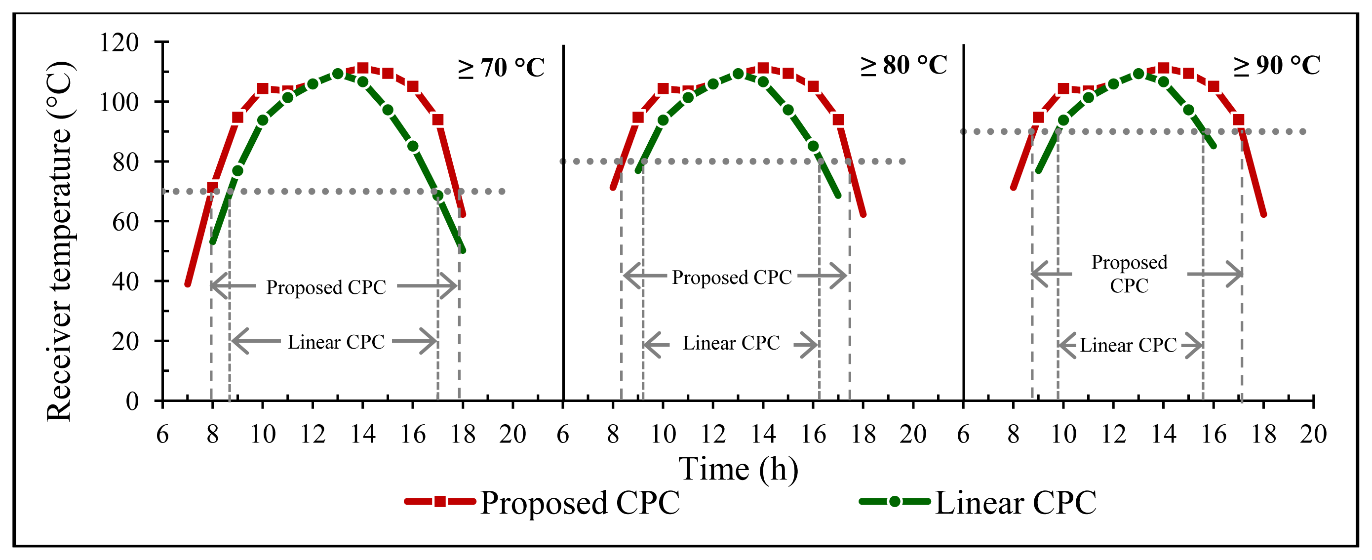
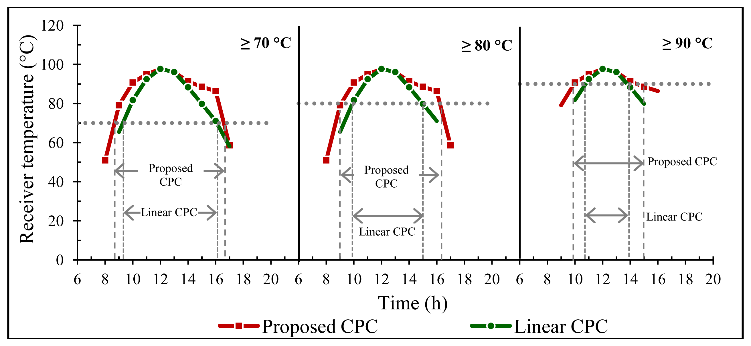
The temperature was estimated for the proposed CPC at the optimum settings (50° bending angle for the east and west wings at a 45° tilt and a 35° tilt of the central part of the CPC) using actual weather data for various seasons in Tokyo. The maximum temperature among the three parts of the CPC was considered as output temperature from the proposed CPC. The temperature from the proposed CPC was compared to that of a linear CPC with same length facing south fixed at an optimum tilt angle of 35°. Temperatures of 70, 80, and 90 °C were considered minimum temperatures required to operate most systems. The length of time over which these temperatures were achieved was investigated for the proposed CPC and compared with a linear south-facing CPC for each temperature. Figure 8 shows the temperatures achieved by the proposed and linear CPCs for May. For 70 and 90 °C, the duration of usable temperatures increases by about 1.2 h for the proposed CPC compare to a linear south-facing CPC and for 80 °C the duration is increased by about 2.2 h.
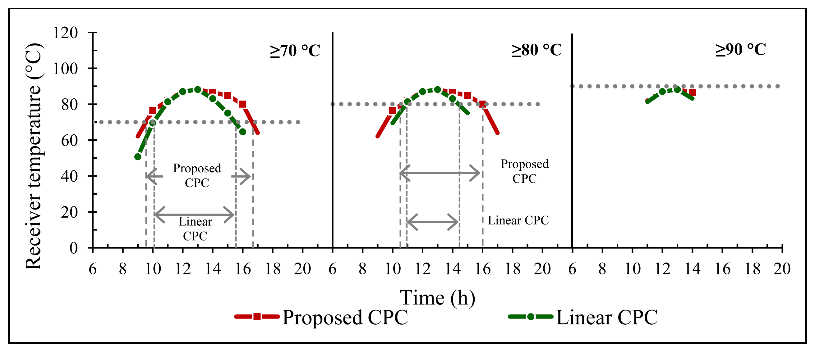
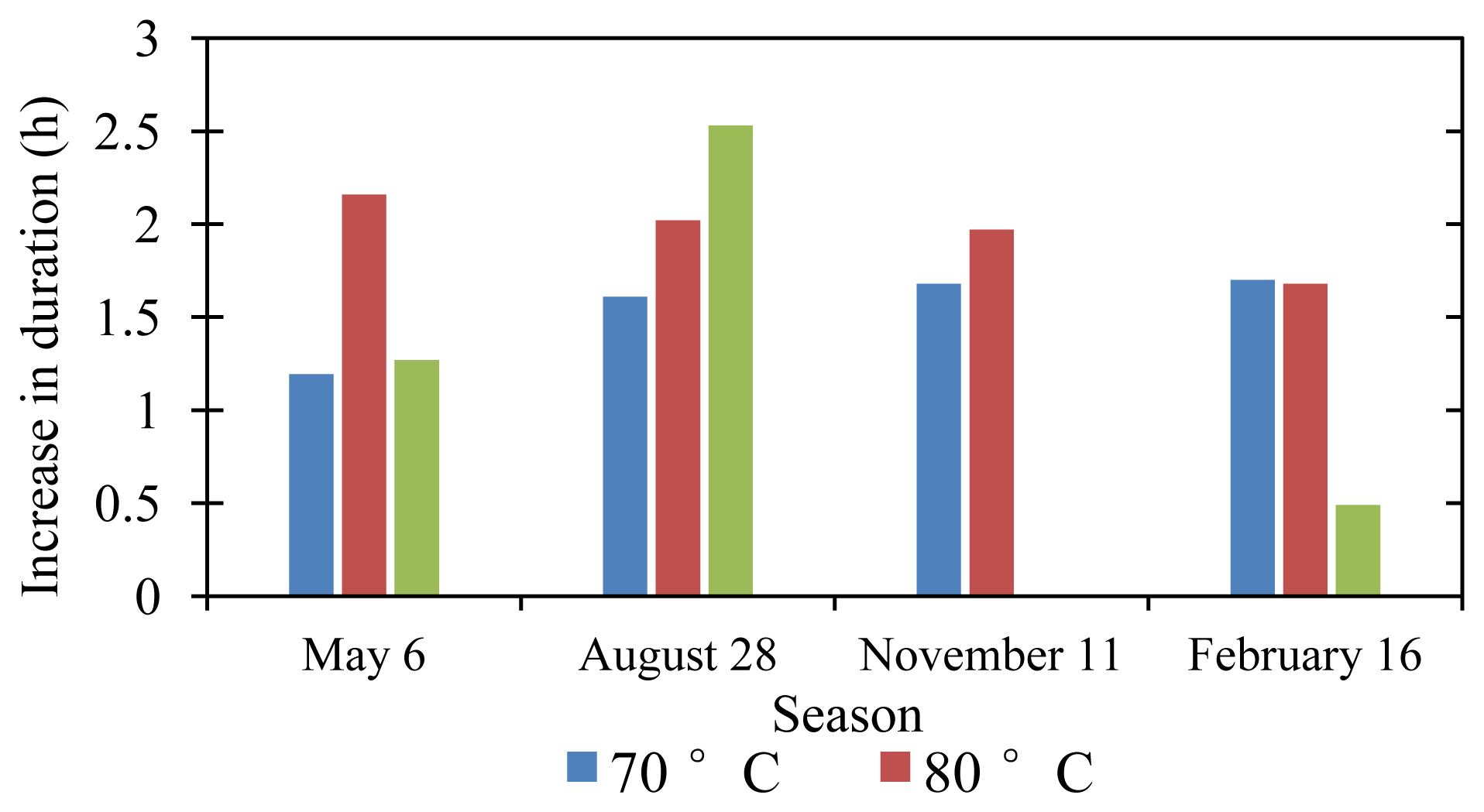
Similar analyses were conducted for the peak summer month of August (Figure 9), autumn (Figure 10), and winter (Figure 11). A summary of the increases in duration with the proposed CPC for various temperature requirements is shown in Figure 12.
In August, the proposed CPC appeared to be more effective; the maximum increase in duration was 2.53 h for a required temperature of 90 °C (Figure 12). In November, a 90 °C temperature was not achieved based on the actual weather data for Tokyo, but for 70 and 80 °C the duration increased by up to 2 h.
In summary, the duration of a usable temperature supply with the proposed CPC increased without tracking or extra cost (since the length of the CPC is same) by up to 2.53 h in the summer and up to 2 h in the winter compared to a linear south-facing CPC. A long-lasting supply of usable temperatures will facilitate stable and smooth operation of solar-driven systems, increasing the performance of entirely solar-driven systems and reducing the cost of operating the backup supply in solar-assisted systems.
5. Conclusions
In this study, a CPC was designed and evaluated with wings angled toward the east and west. The objective was to capture the maximum solar energy in the morning and afternoon to increase the duration of usable temperatures. The total length of the proposed CPC is the same as for a linear CPC, but is divided into three parts; the end parts are angled horizontally and also have a different tilt angle.
The proposed CPC with wings was evaluated using a simulation. Actual measured data for solar beam and diffuse radiation, wind velocity, and ambient temperature were used from Tokyo, Japan. The maximum temperature among the three wings was considered the output temperature from the proposed CPC. The following results were obtained:
The optimum tilt angle for the south-facing central part of the CPC was found to be 35° for year-round operation for Tokyo, Japan.
The optimum tilt and bending angles for the east and west wings were found to be 45° and 50°, respectively.
The overall optimum settings for the proposed CPC were a 35° tilt for the south-facing central part of the CPC and a 45° tilt for the east and west wings angled at 50° for year-round operation in Tokyo, Japan.
The duration of the usable output temperature supply increased by up to 2.53 h at the optimum setting for the proposed CPC compared to a linear south-facing CPC of the same length.
Thus, the proposed CPC with wings can supply usable temperatures for a longer period of time than a conventional linear south-facing collector of the same length. In addition, the proposed design is cost-effective compared to using an expensive tracking system that requires additional maintenance costs. The proposed design also has advantage to provide the required temperature earlier than the water storage tank without the extra maintenance and operational cost. Therefore, the proposed design will help to increase the performance of entirely solar-driven systems and to reduce the cost of solar-assisted systems by reducing the load on the backup supply system.
Conflicts of Interest
The authors declare no conflicts of interest.
Appendix A
The angle of incidence (θi), zenith angle (θz), and solar azimuth angle (γs) used in Equations (4) and (5) are calculated as described below [18]. The values of necessary basic angles are given in Table A1.

| Angle | Description | Value |
|---|---|---|
| ϕ | Latitude of Tokyo | 35.66° |
| β (tilt) | CPC part facing south | Optimized (35°) |
| CPC east and west wings | Optimized (45°) | |
| γ (surface azimuth angle) | CPC part facing south | 0° |
| CPC east and west wings | Optimized (50°) |
The angle of incidence is calculated as:
The zenith angle is calculated as:
The solar azimuth angle is calculated as:
Appendix B
Heat transfer from the CPC cover and receiver were calculated using the relationships shown below [19].
The radiation heat transfer coefficient between the receiver and the cover (hRr) is calculated as:
The radiation heat transfer coefficient between the cover and the sky (hRs) is calculated as:
The convective heat transfer coefficient between the cover and the receiver (hrc) is calculated as:
The convective heat transfer coefficient from the cover due to wind (hca) is calculated as follows:
Nomenclature
| A | area (m2) |
| CP | specific heat (J·kg−1·K−1) |
| CPC | compound parabolic concentrator |
| F | control factor for whether the radiation is accepted by the CPC (1 or 0) |
| hRr | radiation heat transfer coefficient between the receiver and the cover (W·m−2·K−1) |
| hRs | radiation heat transfer coefficient between the cover and the sky (W·m−2·K−1) |
| hrc | convective heat transfer coefficient between the cover and the receiver (W·m−2·K−1) |
| hca | convective heat transfer coefficient from the cover due to wind (W·m−2·K−1) |
| I | solar radiation (W·m−2) |
| M | mass (kg) |
| Q | energy absorbed (W) |
| T | temperature (K) |
| V | velocity (m·s−1) |
| Wab | width of absorber (m) |
| Superscript | |
|---|---|
| nr | average number of reflections |
| Subscripts | |
|---|---|
| ab | absorber |
| air | air |
| ap | aperture |
| bm | beam |
| c | cover |
| cpc | CPC |
| Cu | copper |
| diff | diffuse |
| E | east part of the CPC |
| S | south part of the CPC |
| sky | sky |
| W | west part of the CPC |
| wind | wind |
| Greek Letters | |
|---|---|
| γ | surface azimuth/bending angle (°) |
| θi | angle of incidence (°) |
| θcpc | half acceptance angle (°) |
| θz | zenith angle (°) |
| ϕ | latitude of location (°) |
| δ | declination (°) |
| β | tilt angle (°) |
| γs | solar azimuth angle (°) |
| ω | hour angle (°) |
| α | absorptance |
| ρ | reflectance |
| τ | transmittance |
| σ | Stefan-Boltzmann constant (W·m−2·K−4) |
| ε | emissivity |
References
- Asif, M. Sustainable energy options for Pakistan. Renew. Sustain. Energy Rev. 2009, 13, 903–909. [Google Scholar]
- Ozyurt, O.; Bakırcı, K.; Karslı, S.; Erdogan, S.; Yılmaz, M.; Comaklı, O. Energy production, consumption, and environmental pollution for sustainable development: A case study in Turkey. Renew. Sustain. Energy Rev. 2008, 12, 1529–1561. [Google Scholar]
- Solangi, K.H.; Islam, M.R.; Saidur, R.; Rahim, N.A.; Fayaz, H. A review on global solar energy policy. Renew. Sustain. Energy Rev. 2011, 15, 2149–2163. [Google Scholar]
- Alam, K.C.A.; Saha, B.B.; Akisawa, A. Adsorption cooling driven by solar collector: A case study for Tokyo solar data. Appl. Therm. Eng. 2013, 50, 1603–1609. [Google Scholar]
- Buchter, F.; Dind, P.; Pons, M. An experimental solar-powered adsorptive refrigerator tested in Burkina-Faso. Int. J. Refrig 2003, 26, 79–86. [Google Scholar]
- Hobbi, A.; Siddiqui, K. Optimal design of a forced circulation solar water heating system for a residential unit in cold climate using TRNSYS. Sol. Energy 2009, 83, 700–714. [Google Scholar]
- Islam, M.R.; Sumathy, K.; Khan, S.U. Solar water heating systems and their market trends. Renew. Sustain. Energy Rev. 2013, 17, 1–25. [Google Scholar]
- Chesi, A.; Ferrara, G.; Ferrari, L.; Tarani, F. Analysis of a solar assisted vapour compression cooling system. Renew. Energy 2013, 49, 48–52. [Google Scholar]
- Huang, B.J.; Wu, J.H.; Hsu, H.Y.; Wang, J.H. Development of hybrid solar-assisted cooling/heating system. Energy Convers. Manag 2010, 51, 1643–1650. [Google Scholar]
- Anyanwu, E.E.; Ezekwe, C.I. Design, construction and test run of a solid adsorption solar refrigerator using activated carbon/methanol, as adsorbent/adsorbate pair. Energy Convers. Manag 2003, 44, 2879–2892. [Google Scholar]
- Fan, Y.; Luo, L.; Souyri, B. Review of solar sorption refrigeration technologies: Development and applications. Renew. Sustain. Energy Rev. 2007, 11, 1758–1775. [Google Scholar]
- Shukla, R.; Sumathy, K.; Erickson, P.; Gong, J. Recent advances in the solar water heating systems: A review. Renew. Sustain. Energy Rev. 2013, 19, 173–190. [Google Scholar]
- Fadar, A.E.; Mimet, A.; Pérez-García, M. Modelling and performance study of a continuous adsorption refrigeration system driven by parabolic trough solar collector. Sol. Energy 2009, 83, 850–861. [Google Scholar]
- Li, C.; Wang, R.Z.; Wang, L.W.; Li, T.X.; Chen, Y. Experimental study on an adsorption icemaker driven by parabolic trough solar collector. Renew. Energy 2013, 57, 223–233. [Google Scholar]
- González, M.I.; Rodríguez, L.R. Solar powered adsorption refrigerator with CPC collection system: Collector design and experimental test. Energy Convers. Manag 2007, 48, 2587–2594. [Google Scholar]
- Headley, O.S.; Kothdiwala, A.F.; McDoom, I.A. Charcoal-methanol adsorption refrigerator powered by a compound parabolic concentrating solar collector. Sol. Energy 1994, 53, 191–197. [Google Scholar]
- Kalogirou, S.A. Solar thermal collectors and applications. Prog. Energy Combust. Sci. 2004, 30, 231–295. [Google Scholar]
- Duffie, J.A.; Beckman, W.A. Solar Engineering of Thermal Processes, 2nd ed.; John Willy & Sons: New York, NY, USA, 1991. [Google Scholar]
- Tchinda, R. Thermal behaviour of solar air heater with compound parabolic concentrator. Energy Convers. Manag 2008, 49, 529–540. [Google Scholar]


| Parameter | Value | Unit | Parameter | Value | Unit |
|---|---|---|---|---|---|
| CPC characteristics for each wing | |||||
| Aap | 0.125 | m2 | Ac | 0.125 | m2 |
| Aab | 0.098 | m2 | αc | 0.05 | - |
| Lcpc | 1 | m | τc | 0.89 | - |
| nr | 0.68 | - | - | - | - |
| ρcpc | 0.92 | - | Absorber | - | - |
| τcpc | (ρcpc)nr | - | Mab | 5 | kg |
| τdiff | τcpc | - | CpCu | 386 | J·kg−1·K−1 |
| αab | 0.95 | - | |||
| Cover | - | - | ρab | 0.15 | - |
| Mc | 0.9 | kg | σ | 5.67 × 10⁻⁸ | W·m−2·K−4 |
| Cpc | 840 | J·kg−1 | - | - | - |
© 2014 by the authors; licensee MDPI, Basel, Switzerland. This article is an open access article distributed under the terms and conditions of the Creative Commons Attribution license ( http://creativecommons.org/licenses/by/3.0/).
Share and Cite
Umair, M.; Akisawa, A.; Ueda, Y. Optimum Settings for a Compound Parabolic Concentrator with Wings Providing Increased Duration of Effective Temperature for Solar-Driven Systems: A Case Study for Tokyo. Energies 2014, 7, 28-42. https://doi.org/10.3390/en7010028
Umair M, Akisawa A, Ueda Y. Optimum Settings for a Compound Parabolic Concentrator with Wings Providing Increased Duration of Effective Temperature for Solar-Driven Systems: A Case Study for Tokyo. Energies. 2014; 7(1):28-42. https://doi.org/10.3390/en7010028
Chicago/Turabian StyleUmair, Muhammad, Atsushi Akisawa, and Yuki Ueda. 2014. "Optimum Settings for a Compound Parabolic Concentrator with Wings Providing Increased Duration of Effective Temperature for Solar-Driven Systems: A Case Study for Tokyo" Energies 7, no. 1: 28-42. https://doi.org/10.3390/en7010028