A Long Gravity-Piston Corer Developed for Seafloor Gas Hydrate Coring Utilizing an In Situ Pressure-Retained Method


Abstract
:
1. Introduction

| Types | DSDP-PCB | ODP-PCS | HYACINTH-FPC | HYACINTH-HRC | Japan-PTCS |
|---|---|---|---|---|---|
| Technical parameters | Max. 6 m coring length; 57.8 mm coring diameter; Max. pressure ≤ 35 Mpa | Max. 0.86 m coring length; 42 mm coring diameter; Max. pressure ≤ 70 Mpa | Max. 1 m coring length; 58 mm coring diameter; Max. pressure ≤ 25 Mpa; non-lithological sediment | Max. 1m coring length; 50 mm coring diameter; Max. pressure ≤ 25 Mpa; non-lithological sediment | Max. 3 m coring length; 66 mm coring diameter; Max. pressure ≤ 30 Mpa |
| Pressure-retained methods | ball valve; high pressure nitrogen | ball valve/accumuzlator | A piston seal and a flap seal/accumulator | the piston seal and a flap seal/accumulator | ball valve |
| Temperature-retained methods | Not active | Not active | Not active | Not active | adiabatic and thermoelectric coring liners |
| Post Treatment | Pressure/temperature | No | V-MSCL | V-MSCL | Pressure/temperature |
| Coring History | DSDP 42/62/76 | ODP 124/139/141/146/196 | ODP 194/201/204 IODP 311 India-HGHP-1 China-GMGS-1 Korea-UBGH1 | ODP 194/201/204 IODP 311 India-HGHP-1 | Mackenzie Delta/ Kashiwazaki field and “Nankai Trough” well |
2. A Long Pressure-Retained Corer
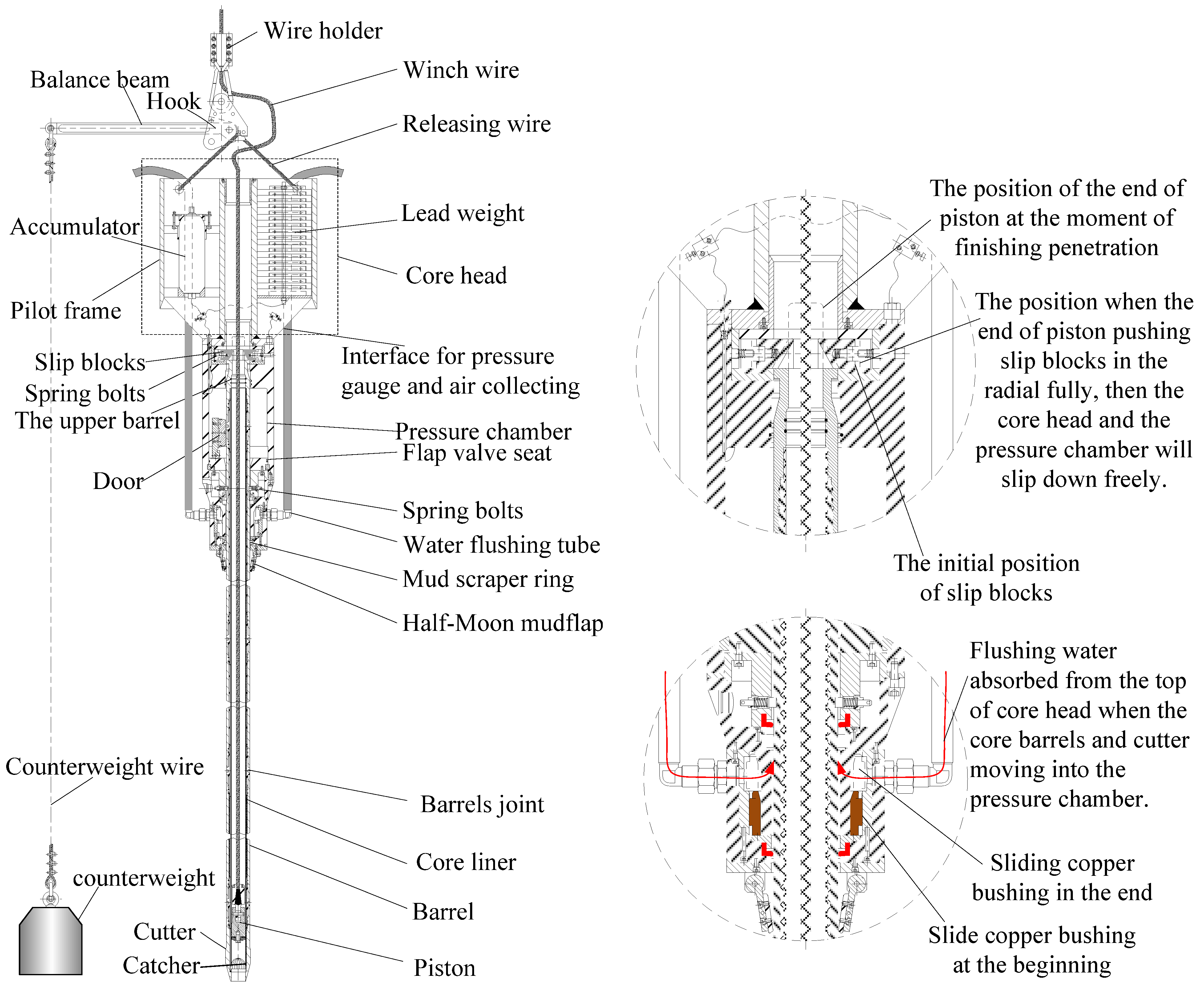
2.1. System Components
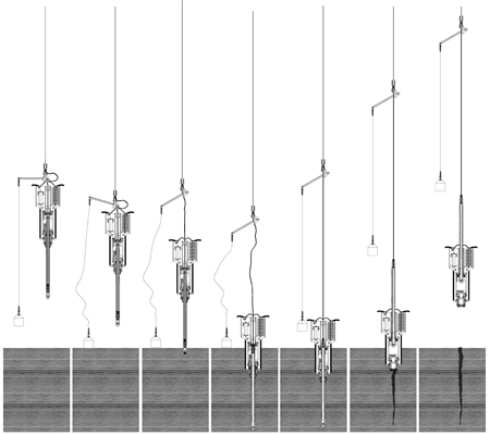
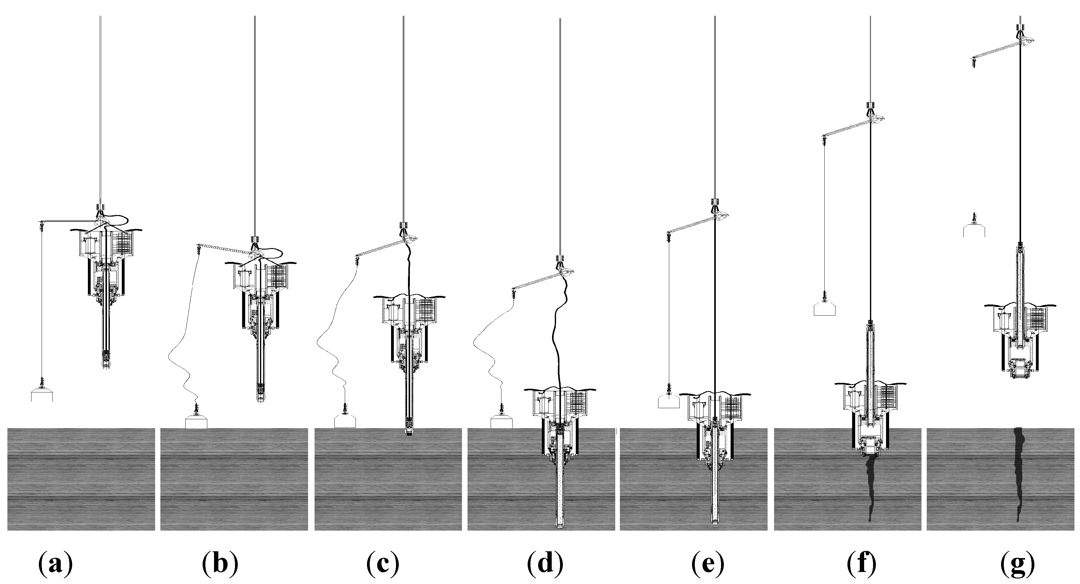
2.2. Principles of Operation


2.3. The Key Structure for Coring with Retained Pressure
- (1)
- The outer diameter of the screw-threaded barrel joint is the same as that of the barrels, allowing the whole set of core barrels to slip freely upward along the center hole of the pressure chamber, while gravity-piston corers normally have coupling sleeves with a little larger outer diameter; However the piston corer presented in this paper has a cutter with a larger outer diameter than that of the barrels; this creates a seal between the cutter and the pressure chamber at the bulge of the cutter.
- (2)
- The core head and the pressure chamber are assembled integrally, acting as the dead weight to penetrate. The core head is made of the pilot frame, lead weight and two accumulators.
- (3)
- The four major sealing structures that retain pressure on the core include the seal between the piston and the upper section of the core barrels (Figure 3a), the seal between the coring cutter and the upper opening of the pressure chamber, the seal between the door and the flap valve seat (Figure 3b), the seal between the screw-threaded coupling sleeve and both sides of two barrels (Figure 3c), and two accumulators mounted in the pilot frame, the accumulators are used to compensate for the change of volume due to the change of pressure between the inside and the outside of the barrels and the pressure chamber when the corer is pulled up on board.
- (4)
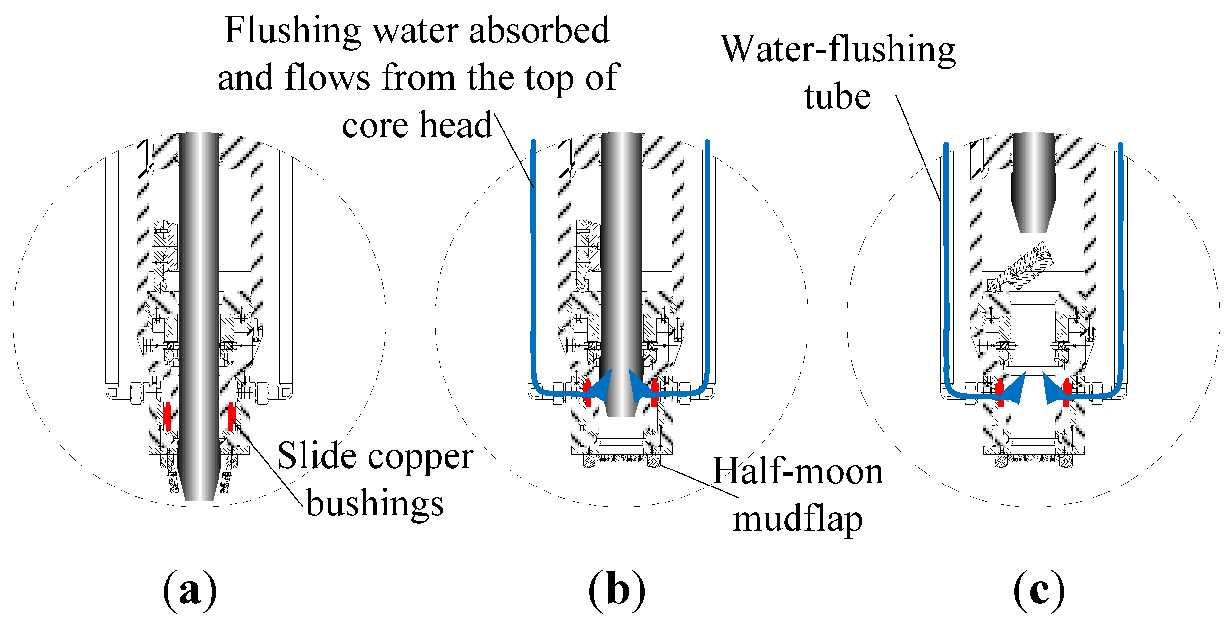
- Two water-flushing tubes are mounted on both sides of the mud flap because there was a failure to maintain pressure without these tubes during the first sea trial. It was found that the door of the flap valve was not easy to fully close with mud on the conical surface of the flap valve seat. Furthermore, when the core head and the pressure chamber would slip down along the core barrels and penetrate the mud near the seabed, there would be an enclosed space at the bottom of the pressure chamber. When the winch wire lifts up the core barrels, the sediment is absorbed under the cutter and flows into the mud flap and the pressure chamber like a syringe pump. After the flushing tubes were mounted, the flushing water could be absorbed easily through the tubes from the top of the core head and would compensates for the increasing space between the cutter and the sediment below; meanwhile, the flushing water could clean the mud on the conical surface of the flap valve seat (Figure 4). Although the half-moon flap can block the mud flowing up into the pressure chamber, sometimes the half-moon flap would not work when the corer sinks into harder sediment stratum. There were more chances to succeed after mounting the unit after the first sea trial.

- (5)
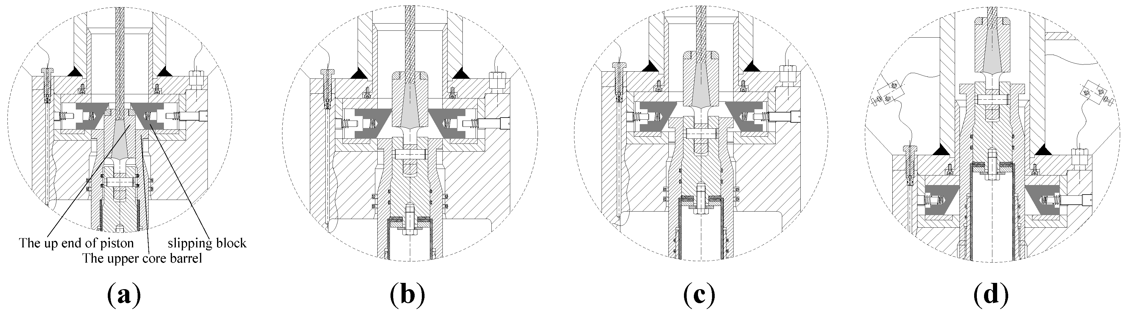
- In the corer’s descending process, the barrels are hooked by four equally spaced spring bolts in the mud-blocking unit (Figure 5). When the releasing wire is removed, the core head and the pressure chamber with the mud-blocking unit lose their bearing force by the four spring bolts; then they slip down along the slopes in the four grooves on one of the barrels and push the spring bolts radially. Thus, the dead weight of the core head and the pressure chamber with the mud-blocking unit act on the top surface of upper barrels (Figure 6a) and force the barrels to penetrate the sediment and make the core “flow into” the core liners. When the piston and the barrels are raised up, the four spring bolts mounted on the upper pressure chamber (Figure 6b) are pushed radially by the end of the piston; at that time, the end of the upper barrel acts directly upon the slopes of the four stiff slip blocks of the spring bolts, which are made of quenched-and-tempered stainless steel-3Cr13. Due to the dead weight of the core head, the pressure chamber and the mud-blocking unit, the four slip blocks are forced to move along the horizontal grooves (Figure 6c). The barrels are raised along with the piston (Figure 6d), and thus the core head and the pressure chamber freely slip down along the outer surface of the barrels.
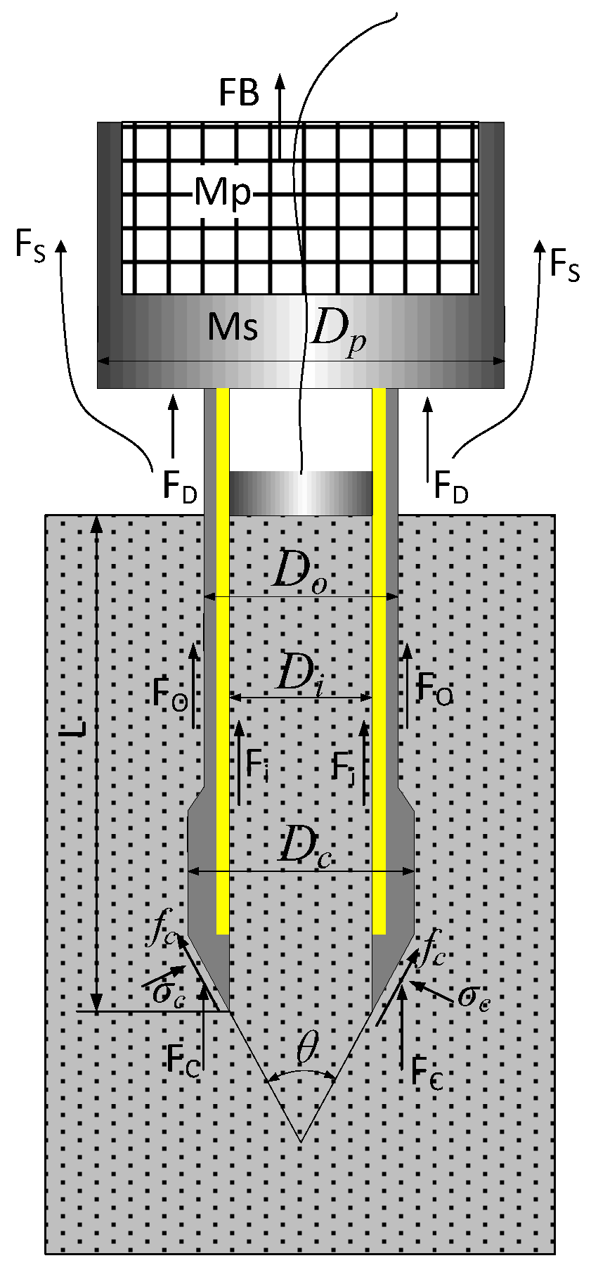
3. Mechanism of the Core

3.1. Inner Surface Friction Force
3.2. Outer Surface Friction Force
3.3. Resistance of the Cutter
3.4. The Underwater Lead Weight of the Corer
3.5. The Drag Force in Water
3.6. Penetration Control Equation
3.7. The Uplift Force of the Corer
4. Results and Discussion
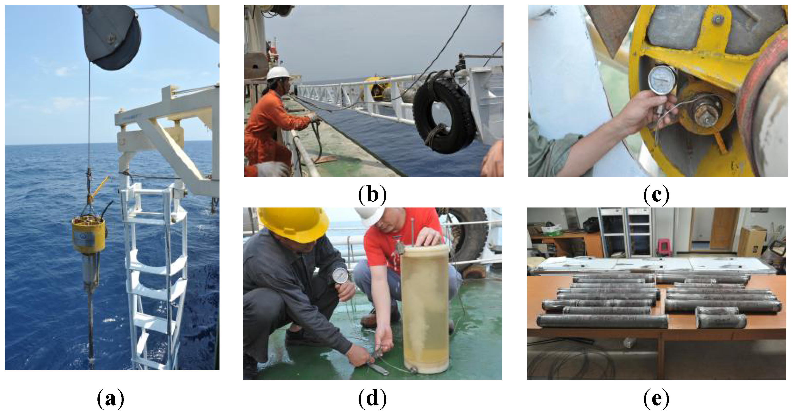
4.1. Sea Trials
| Site Name | Date | Location | Ld (m) | Pc (MPa) | Lc (cm) | Mc (kg) | Specifics of Corer |
|---|---|---|---|---|---|---|---|
| 387PC | 15 August 2006 | Paracel Islands | 1400 | 0 | 900 | 1300 | OD 105 mm; ID 75 mm |
| 373PC | 16 August 2006 | Paracel Islands | 1400 | 14 | 900 | 1300 | OD 105 mm; ID 75 mm |
| DSH-1 | 19 August 2006 | Pratas Islands | 3150 | 0 | 160 | 1300 | OD 105 mm; ID 75 mm |
| DSH-1 | 19 August 2006 | Pratas Islands | 3050 | 0 | 0 | 1300 | OD 105 mm; ID 75 mm |
| DSH-1 | 20 August 2006 | Pratas Islands | 3050 | 0 | 753 | 1300 | OD 105 mm; ID 75 mm |
| DSH-1A | 20 August 2006 | Pratas Islands | 3050 | 30 | 658 | 1300 | OD 105 mm; ID 75 mm |
| DSH-1C-1 | 22 August 2006 | Pratas Islands | 3050 | 32 | 659 | 1300 | OD 105 mm; ID 75 mm |
| DSH-1C-2 | 22 August 2006 | Pratas Islands | 3050 | 0 | 624 | 1500 | OD 105 mm; ID 75 mm |
| DSH-7 | 23 August 2006 | Pratas Islands | 3050 | 32 | 957 | 1500 | OD 105 mm; ID 75 mm |
| DSH-9 | 23 August 2006 | Pratas Islands | 3050 | 34 | 957 | 1500 | OD 105 mm; ID 75 mm |
| DSH-1D | 24 August 2006 | Pratas Islands | 3050 | 0 | 963 | 1500 | OD 105 mm; ID 75 mm |
| DSH-13 | 24 August 2006 | Pratas Islands | 3050 | 0 | 884 | 1500 | OD 105 mm; ID 75 mm |
| Jiulong Reef | 25 August 2006 | Jiulong Reef | 760 | 9 | 20 | 1500 | OD 105 mm; ID 75 mm |
| Jiulong Reef | 25 August 2006 | Jiulong Reef | 760 | 2 | 500 | 1500 | OD 105 mm; ID 75 mm |
| BZ888 | 9 May 2006 | 115°26.0922' E/19°18.8040' N | 2470 | 0 | 944 | 1300 | OD 105 mm; ID 75 mm |
| BZ526PC | 26 May 2006 | 111°47.0962' E/17°45.1193' N | 1940 | 20 | 915 | 1300 | OD 105 mm; ID 75 mm |
| DHCL12 | 17 April 2011 | 118°47.4258' E/22°00.8804' N | 1023 | 9.5 | 12.1 | 1800 | OD 112 mm; ID 90 mm |
| 973-4 | 22 April 2011 | 118°49.0818' E/21°54.3247' N | 1600 | 16.5 | 14.5 | 2500 | OD 112 mm; ID 90 mm |
| DHCL13 | 25 April 2011 | 118°44.6179' E/22°01.5884' N | 850 | 8.8 | 9.7 | 2500 | OD 112 mm; ID 90 mm |
| 9735 | 26 April 2011 | 119°11.0066' E/21°18.5586' N | 3050 | 0 | 9.65 | 2500 | OD 112 mm; ID 90 mm |
| PPC1 | 20 May 2011 | 116°53.4988' E/17°51.9969' N | 4000 | 2 | 18.5 | 2500 | OD 112 mm; ID 90 mm |

4.2. Discussion
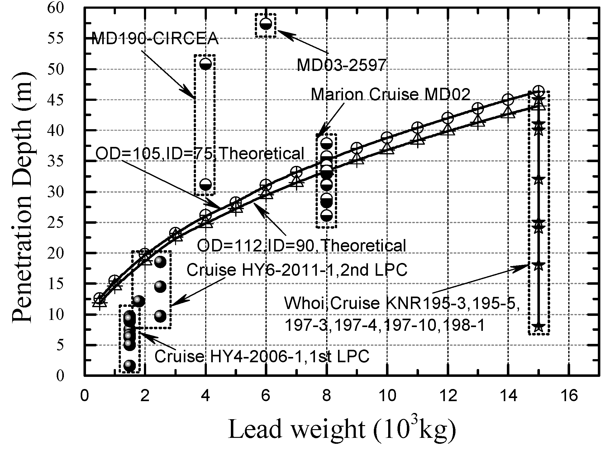
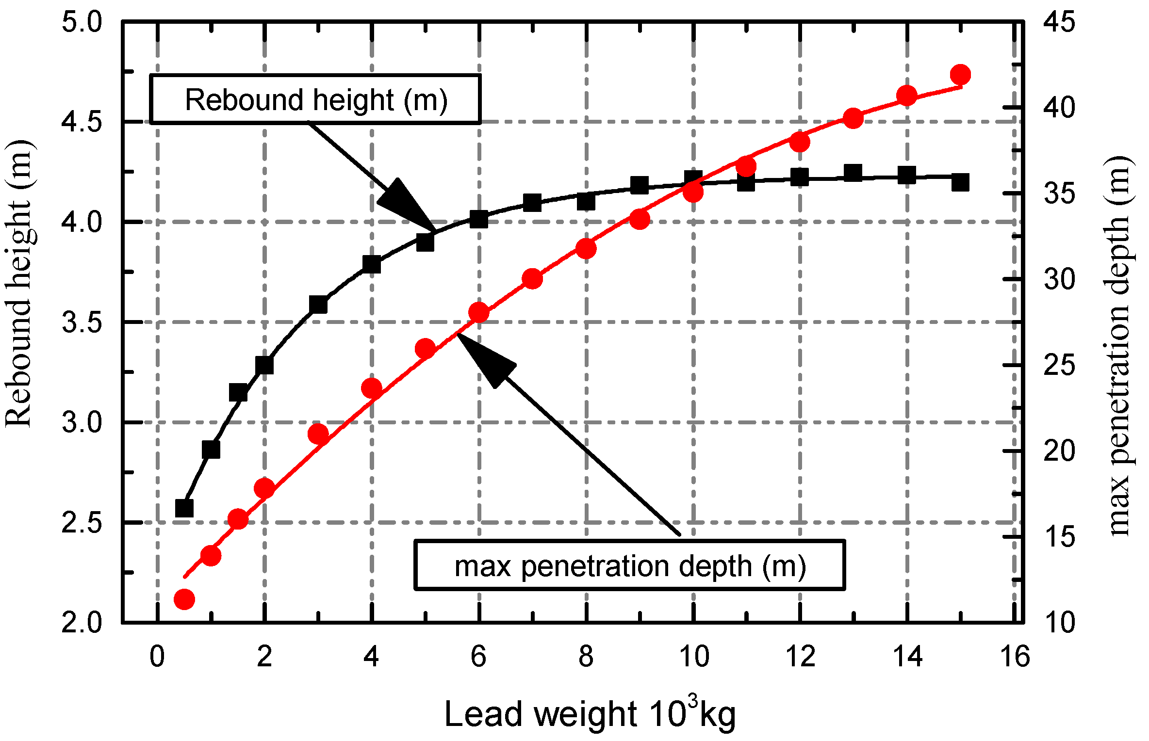
4.2.1. Influence of Lead Weight on Coring Depth

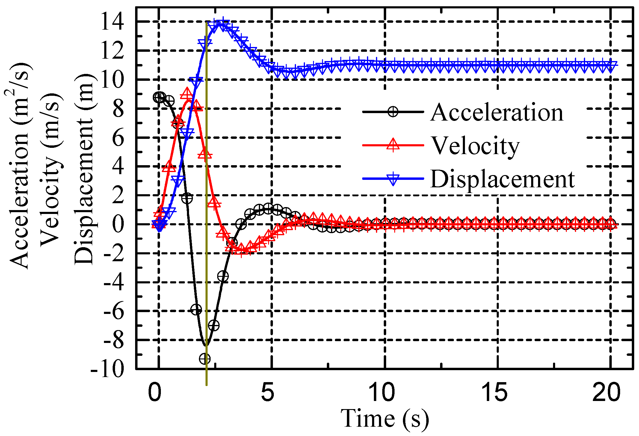
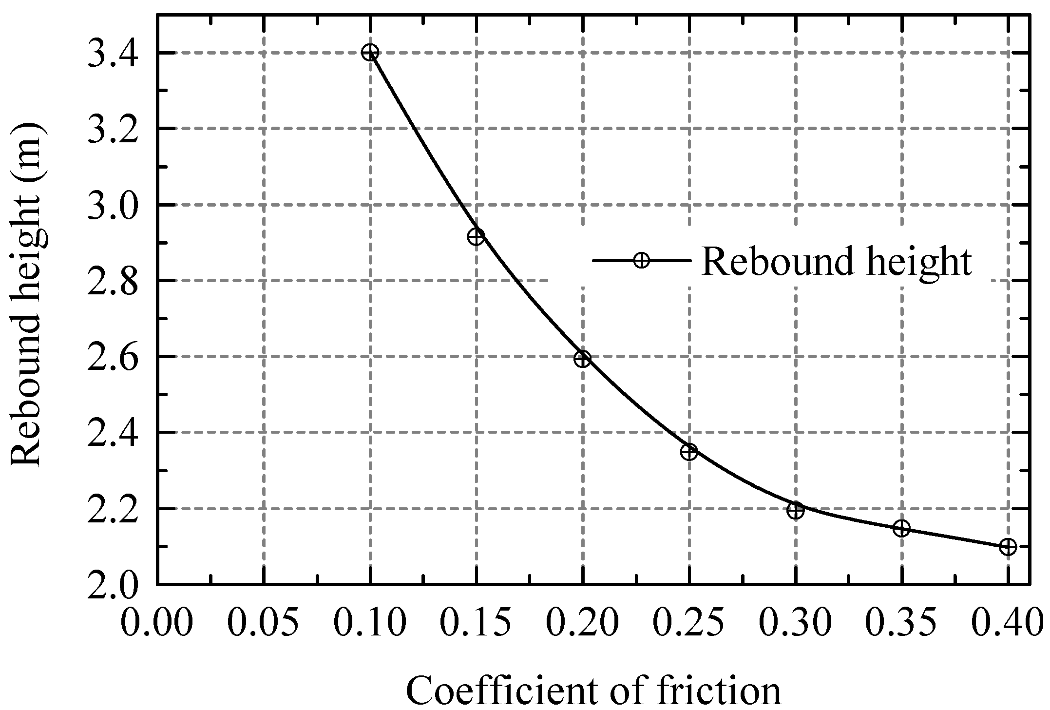
4.2.2. Analysis of the Coring Process

4.2.3. Influence of the Inner Diameter of the Coring Liner

4.2.4. Influence of the Outer Diameter of the Coring Barrels on the Coring Process

4.2.5. The Release Time is Difficult to Determine in Practice
4.2.6. The Door of the Flap Valve Makes It Difficult to Ensure Complete Sealing
5. Outlook
Acknowledgments
Conflict of Interest
References
- Makogon, Y.F.; Holditch, S.A.; Makogon, T.Y. Natural gas-hydrates—A potential energy source for the 21st Century. J. Pet. Sci. Eng. 2007, 56, 14–31. [Google Scholar] [CrossRef]
- Zhao, J.F.; Yu, T.; Song, Y.C.; Liu, D.; Liu, W.G.; Liu, Y.; Yang, M.J.; Ruan, X.K.; Li, Y.H. Numerical simulation of gas production from hydrate deposits using a single vertical well by depressurization in the Qilian Mountain permafrost, Qinghai-Tibet Plateau, China. Energy 2013, 52, 308–319. [Google Scholar] [CrossRef]
- Rutherford, S.R.; Williams, R.H. Amplitude-versus-offset variations in gas sands. Soc. Explor. Geophys. 1989, 54, 680–688. [Google Scholar]
- Baristeas, N.; Anka, Z.; di Primio, R.; Rodriguez, J.F.; Marchal, D.; Dominguez, F. Distribution of hydrocarbon leakage indicators in the Malvinas Basin offshore Argentine continental margin. Mar. Geol. 2012, 332–334, 56–74. [Google Scholar]
- Li, L.; Lei, X.H.; Zhang, X.; Sha, Z.B. Gas hydrate and associated free gas in the Dongsha Area of northern South China Sea. Mar. Pet. Geol. 2013, 39, 92–101. [Google Scholar] [CrossRef]
- Wu, S.; Zhang, G.; Huang, Y.; Liang, J.; Wong, H.K. Gas hydrate occurrence on the continental slope of the northern South China Sea. Mar. Pet. Geol. 2005, 22, 403–412. [Google Scholar] [CrossRef]
- McDonnell, S.L.; Max, M.D.; Cherkis, N.Z.; Czarnecki, M.F. Tectono-sedimentary controls on the likelihood of gas hydrate occurrence near Taiwan. Mar. Pet. Geol. 2000, 17, 929–936. [Google Scholar] [CrossRef]
- Shyu, C.T.; Chen, Y.J.; Chiang, S.T.; Liu, C.S. Heat flow measurements over bottom simulating reflectors, offshore southwestern Taiwan. Terr. Atmos. Ocean Sci. 2006, 17, 845–869. [Google Scholar]
- Zhao, J.F.; Cheng, C.X.; Song, Y.C.; Liu, W.G.; Liu, Y.; Xue, K.H.; Zhu, Z.H.; Yang, Z.; Wang, D.Y.; Yang, M.J. Heat transfer analysis of methane hydrate sediment dissociation in a closed reactor by a thermal method. Energies 2012, 5, 1292–1308. [Google Scholar] [CrossRef]
- Zhao, J.F.; Yao, L.; Song, Y.C.; Xue, K.H.; Cheng, C.X.; Liu, Y.; Zhang, Y. In situ observations by magnetic resonance imaging for formation and dissociation of tetrahydrofuran hydrate in porous media. Magn. Reson. Imaging 2011, 29, 281–288. [Google Scholar] [CrossRef] [PubMed]
- Dickens, G.R.; Paull, C.K.; Wallace, P. Direct measurement of in situ methane quantities in a large gas-hydrate reservoir. Nature 1997, 385, 426–428. [Google Scholar] [CrossRef]
- Smith, E.A.L. Pile-driving analysis by the wave equation. Trans. Am. Soc. Civil. Eng. 1962, 127, 1145–1193. [Google Scholar]
- Coulomb, C.A. Essai sur uneapplication des règles de maximis et minimis à quelques problèmes de statique, relatifs à l'architecture [in French]. Mém. Math. Phys. 1776, 7, 343–382. [Google Scholar]
- Silva, A.J.; Hollister, C.D.; Laine, E.P.; Beverly, B.E. Geotechnical properties of deep sea sediments: Bermuda Rise. Mar. Geotech. 1976, 1, 195–232. [Google Scholar] [CrossRef]
- Smith, G.N.; Smith, I. Elements of Soil Mechanics, 8th ed.; Wiley-Blackwell Publishing: Edinburgh, UK, 1998. [Google Scholar]
- Paik, K.; Lee, S. Behaviour of soil plugs in open-ended model piles driven into sands. Mar. Geores. Geotech. 1993, 11, 353–373. [Google Scholar] [CrossRef]
- Skinner, L.C.; McCave, I. Analysis and modelling of gravity- and piston coring based on soil mechanics. Mar. Geol. 2003, 199, 181–204. [Google Scholar] [CrossRef]
- Munson, B.R.; Young, D.F.; OkIIshi, T.H.; Huebsch, W.W. Fundamentals of fluid mechanics, 6th ed.; John Wiley & Sons: New York, NY, USA, 1994; Volume 3, pp. 597–598. [Google Scholar]
- Murthy, V.N.S. Geotechnical Engineering: Principles and Practices of Soil Mechanics and Foundation Engineering; Taylor & Francis: New York, NY, USA, 2002. [Google Scholar]
- Curry, W.; Broda, J.; Keigwin, L.; Mountain, G.; Pisias, N. A new long coring system for R/V Knorr. Eos Trans. Am. Geophys. Union 2008, 89, 142–143. [Google Scholar] [CrossRef]
- Maddison, E.J.; Pike, J.; Dunbar, R. Seasonally laminated diatom-rich sediments from Dumont d’Urville Trough, East Antarctic Margin: Late-Holocene Neoglacial sea-ice conditions. Holocene 2012, 22, 857–875. [Google Scholar] [CrossRef]
- State Key Laboratory of Marine Geology, Tongji University. The joint voyage between China and France in South China Sea [in Chinese]. Mar. Geol. Quat. Geol. 2012, 4, 106. [Google Scholar]
- Chen, Y.F.; Matsumoto, R.; Paull, C.K.; Ussler, W., III; Lorenson, T.; Hart, P.; Winters, W. Methane-derived authigenic carbonates from the northern Gulf of Mexico—MD02 Cruise. J. Geochem. Explor. 2007, 95, 1–15. [Google Scholar] [CrossRef]
- Meyerhof, G.G. The ultimate bearing capacity of foundations. Geotechnique 1951, 1, 301–332. [Google Scholar] [CrossRef]
- Meyerhof, G.G. Bearing capacity and settlement of pile foundations. J. Geotech. Geoenviron. Eng. 1976, 102, 197–228. [Google Scholar]
- Schultheiss, P.; Holland, M.; Roberts, J.; Huggett, Q.; Druce, M.; Fox, P. PCATs: Pressure Core Analysis and Transfer System. In Proceedings of the 7th International Conference on Gas Hydrates (ICGH 2011), Edinburgh, UK, 17–21 July 2011.
© 2013 by the authors; licensee MDPI, Basel, Switzerland. This article is an open access article distributed under the terms and conditions of the Creative Commons Attribution license (http://creativecommons.org/licenses/by/3.0/).
Share and Cite
Chen, J.-W.; Fan, W.; Bingham, B.; Chen, Y.; Gu, L.-Y.; Li, S.-L. A Long Gravity-Piston Corer Developed for Seafloor Gas Hydrate Coring Utilizing an In Situ Pressure-Retained Method. Energies 2013, 6, 3353-3372. https://doi.org/10.3390/en6073353
Chen J-W, Fan W, Bingham B, Chen Y, Gu L-Y, Li S-L. A Long Gravity-Piston Corer Developed for Seafloor Gas Hydrate Coring Utilizing an In Situ Pressure-Retained Method. Energies. 2013; 6(7):3353-3372. https://doi.org/10.3390/en6073353
Chicago/Turabian StyleChen, Jia-Wang, Wei Fan, Brian Bingham, Ying Chen, Lin-Yi Gu, and Shi-Lun Li. 2013. "A Long Gravity-Piston Corer Developed for Seafloor Gas Hydrate Coring Utilizing an In Situ Pressure-Retained Method" Energies 6, no. 7: 3353-3372. https://doi.org/10.3390/en6073353