1. Introduction
In recent years, a new power-split hybrid system called compound-structure permanent-magnet synchronous machine (CS-PMSM) system has been developed, aiming to get rid of the mechanical planetary gear while retaining the continuously variable transmission (CVT) function [
1,
2,
3,
4]. CS-PMSMs can replace the gearbox, flywheel, clutch, starting motor and generator used in traditional automobiles. Moreover, in a hybrid system equipped with the BDRM, the engine only provides average power of the vehicle, so its size will be smaller than that in traditional automobiles. However, brushes and slip rings are a short board in the existing topology of CS-PMSM [
5,
6,
7,
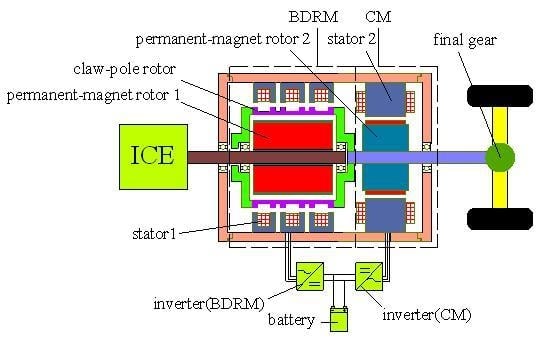
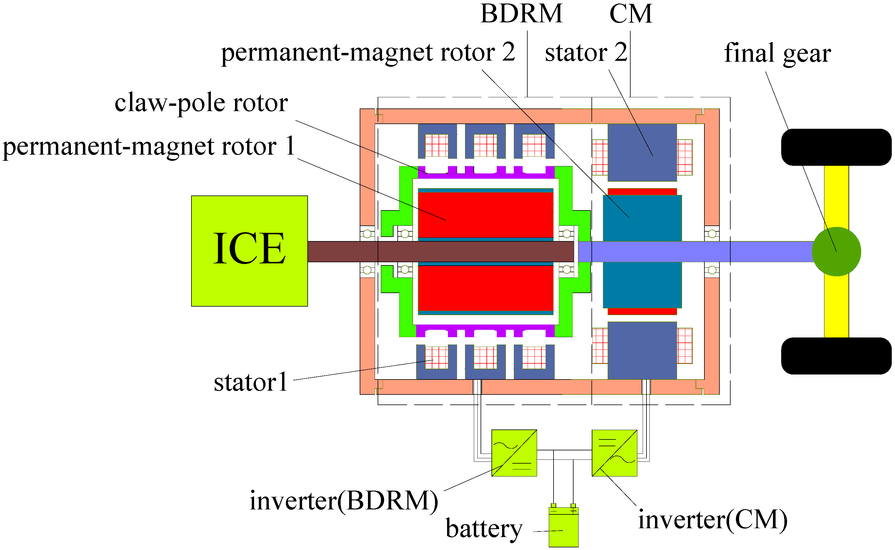
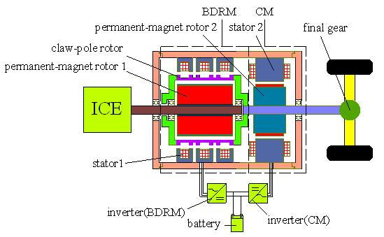
8]. To solve this problem, a novel brushless CS-PMSM that consists of one brushless double rotor machine (BDRM) and one conventional machine (CM) is proposed, as shown in
Figure 1.
Figure 1.
Novel brushless CS-PMSM system.
Figure 1.
Novel brushless CS-PMSM system.
As the key part of the brushless CS-PMSM system, the BDRM implements brushless technology for a double rotor machine. There have been several proposals for double rotor machines in the past. Fan and Wen [
6] have proposed a brushless permanent magnet dual mechanical port machine (BLDMPM) for HEV use. This machine uses the claw pole structure and is based on the principle of a disc type electric machine. Due to the special teeth-pole pattern in BLDMPM, its torque has a strong pulsation component. Moreover, Zheng [
9] has presented a radial magnetic-field-modulated brushless double-rotor machine (MFM-BDRM). It is based on the principle of magnetic field modulation. The MFM-BDRM is a promising technology for HEV drive systems, but there are still some problems to be solved in the prototyping. Compared with other proposals of double rotor machines, some advantages of the BDRM can be summarized as follows:
- (1)
BDRM’s windings are mounted on the stator which is close to the motor case, so the windings have good heat dissipation;
- (2)
There is no coupling between the stator phases, so the BDRM can be easily designed to be a multiphase structure;
- (3)
It is appropriate that the BDRM is designed to be a multi-pole machine, so the BDRM is suitable for intermediate or high frequency operation;
- (4)
BDRM’s ring shaped windings are simple and the stator processing is convenient.
In this paper, the torque characteristics and power factor of the BDRM are investigated. Based on the analysis results, a prototype was manufactured and the experimental results provided.
2. Structure and Operating Principle
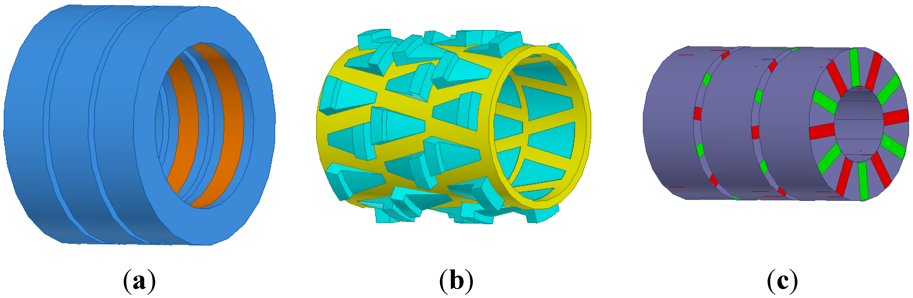
Figure 2 shows the exploded view of the BDRM. It is a synchronous machine with a stator, claw-pole outer rotor and permanent-magnet inner rotor. The stator comprises laminated iron cores and ring-shaped windings, as shown in
Figure 2a. The claw-pole rotor has three arrays of claws placed in non-magnetic bracket as shown in
Figure 2b.
Figure 2c shows the permanent-magnet rotor which is built in a flux-concentrated magnet topology.
Figure 2.
Exploded view of the BDRM: (a) stator; (b) claw-pole rotor; (c) permanent-magnet rotor.
Figure 2.
Exploded view of the BDRM: (a) stator; (b) claw-pole rotor; (c) permanent-magnet rotor.
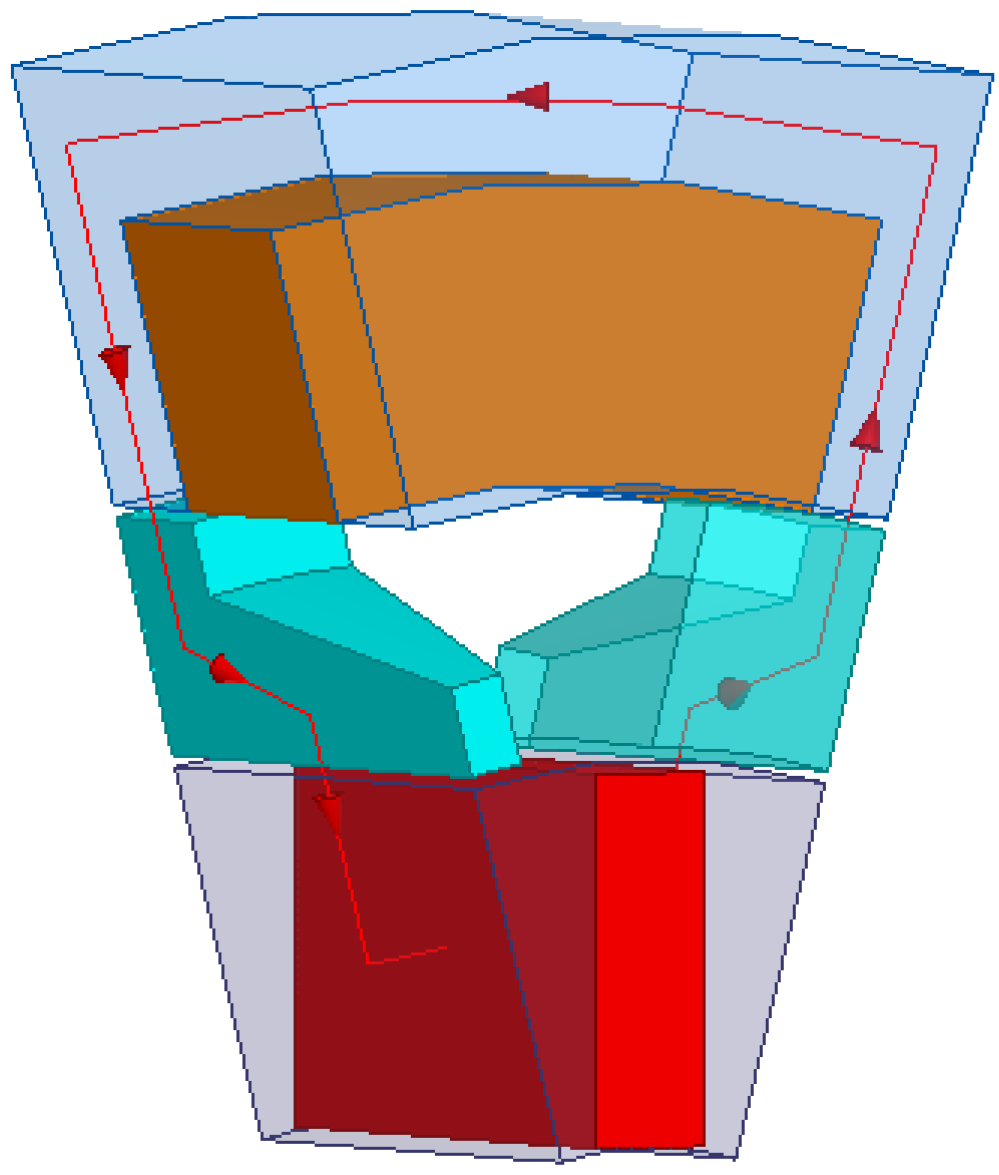
The flux path in one pole of the BDRM is shown in
Figure 3. The flux from the magnet goes radially through the inner air gap into one claw, then across the outer air gap and into the stator, passing axially along the yoke, and once again radially passing the outer air gap into the next claw, and finally returns to the opposite polarity of the magnet, completing a flux loop.
Brushless technology for a double-rotor machine is realized, which makes the BDRM a meaningful invention. When used in hybrid electric vehicle traction, the permanent-magnet rotor is connected to the crank shaft of the internal combustion engine (ICE), while the claw-pole rotor is connected to the final drive. The function of permanent-magnet rotor is to transfer the torque of the ICE to claw-pole rotor with the assistance of the stator. When stator windings are electrified with different frequencies (via inverter), the speed adjustment between claw-pole rotor and permanent-magnet rotor can be realized.
The claw-pole rotor is connected to load shaft together with the CM, as shown in
Figure 1. Without considering the static friction, the speed and torque equations on the outgoing shaft are shown as follows:
where
,
are the mechanical angular speeds of the claw-pole rotor and the load;
TCM is the torque of the CM, which can be positive and negative, depending on the torque difference between the ICE and output demand; and
TBDRM is the torque of the BDRM.
It can be seen from Equation (2) that the output torque of the shaft comprises the torque of the BDRM and the torque of the CM. By controlling the torque provided by CM, the engine torque can be regulated for high efficiency operation independent of load torque.
Figure 3.
Flux path in one pole of the BDRM.
Figure 3.
Flux path in one pole of the BDRM.
3. Parametric Influences on Electromagnetic Torque
As the stator has ring-shaped centralized windings, a new definition of electric loading is given as the current sum per axial armature length:
where
N is the number of stator-coil turns;
I is its current value;
lef is the effective axial length of single-phase BDRM.
Then the back electromotive force (BEMF) can be calculated by:
where
f is the frequency of the stator winding current (Hz);
kw is the winding factor;
p is the pole-pair number;
Φ is the main flux from each pole (Wb).
The electromagnetic torque could be expressed as:
where
m is the phase number;
J is the current density (A/m
2);
Sc is the cross-sectional area of the conductor (m
2);
ψ is the leading angle of load current
I to no-load BEMF
E0;
Ωs is the synchronous angular speed (rad/s).
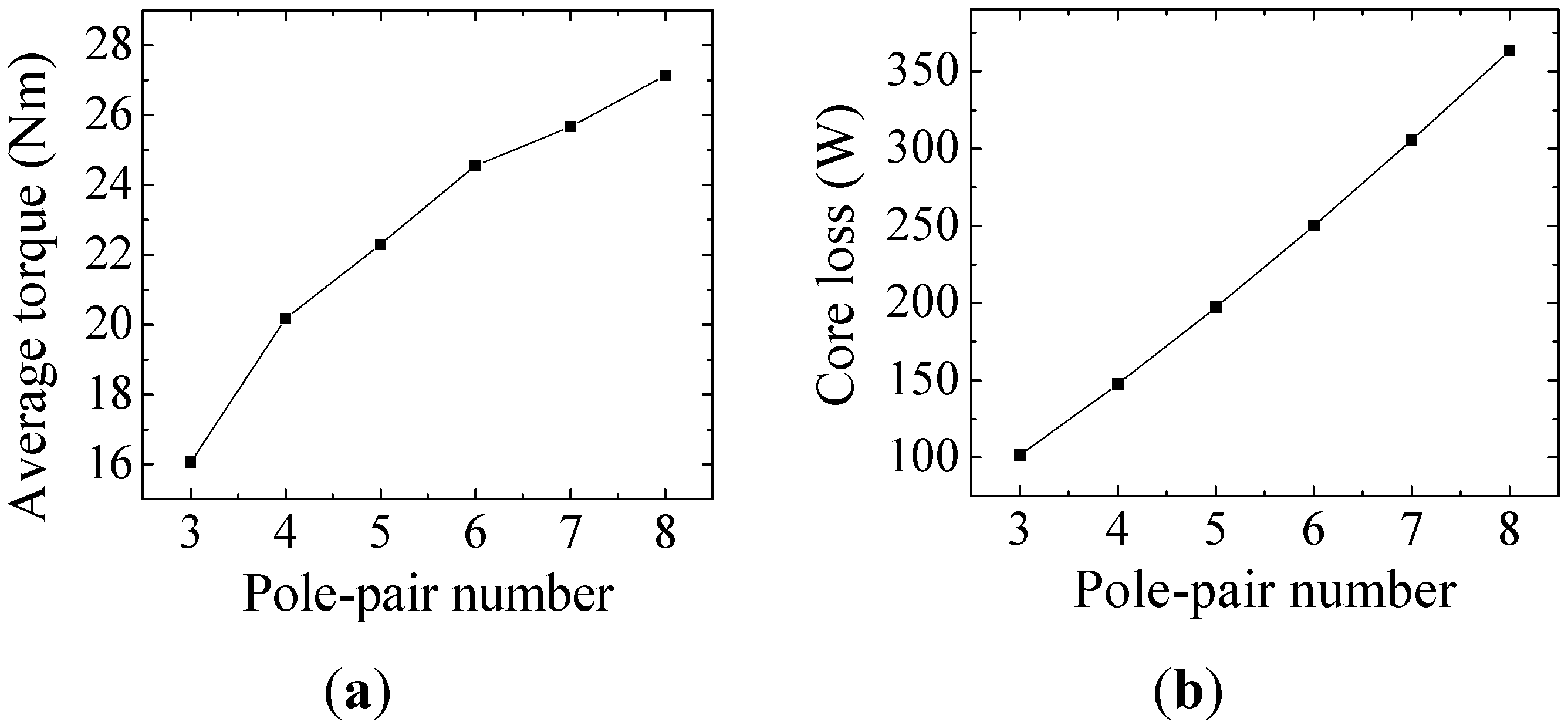
The BDRM has homopolar flux in the stator cores. This allows an increase in the electromagnetic torque with an increase in the pole-pair number for given geometrical dimensions and current loading. However, the electrical frequency also increases with pole-pair number, which will lead to excessive core loss [
10,
11]. The 3D finite element method (FEM) was carried out to compute the average torque and the core loss.
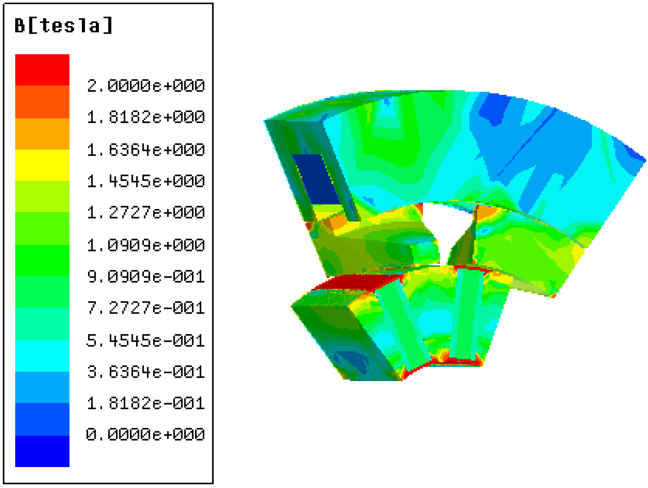
Figure 4 shows the no-load flux density distribution of one model at maximum linked flux.
Figure 5 shows the variation of average torque and core loss versus the pole-pair number, these models are built with the same dimensions. A compromise between the output torque and the core loss has been made, and the pole-pair number is chosen as six.
Figure 4.
No-load flux density distribution at maximum linked flux.
Figure 4.
No-load flux density distribution at maximum linked flux.
Figure 5.
Variation of BDRM’s performance versus the pole-pair number: (a) average torque; (b) core loss.
Figure 5.
Variation of BDRM’s performance versus the pole-pair number: (a) average torque; (b) core loss.
4. Power Factor Improvement
Results from analytical and FEM calculations show that the power factor of BDRM is low [
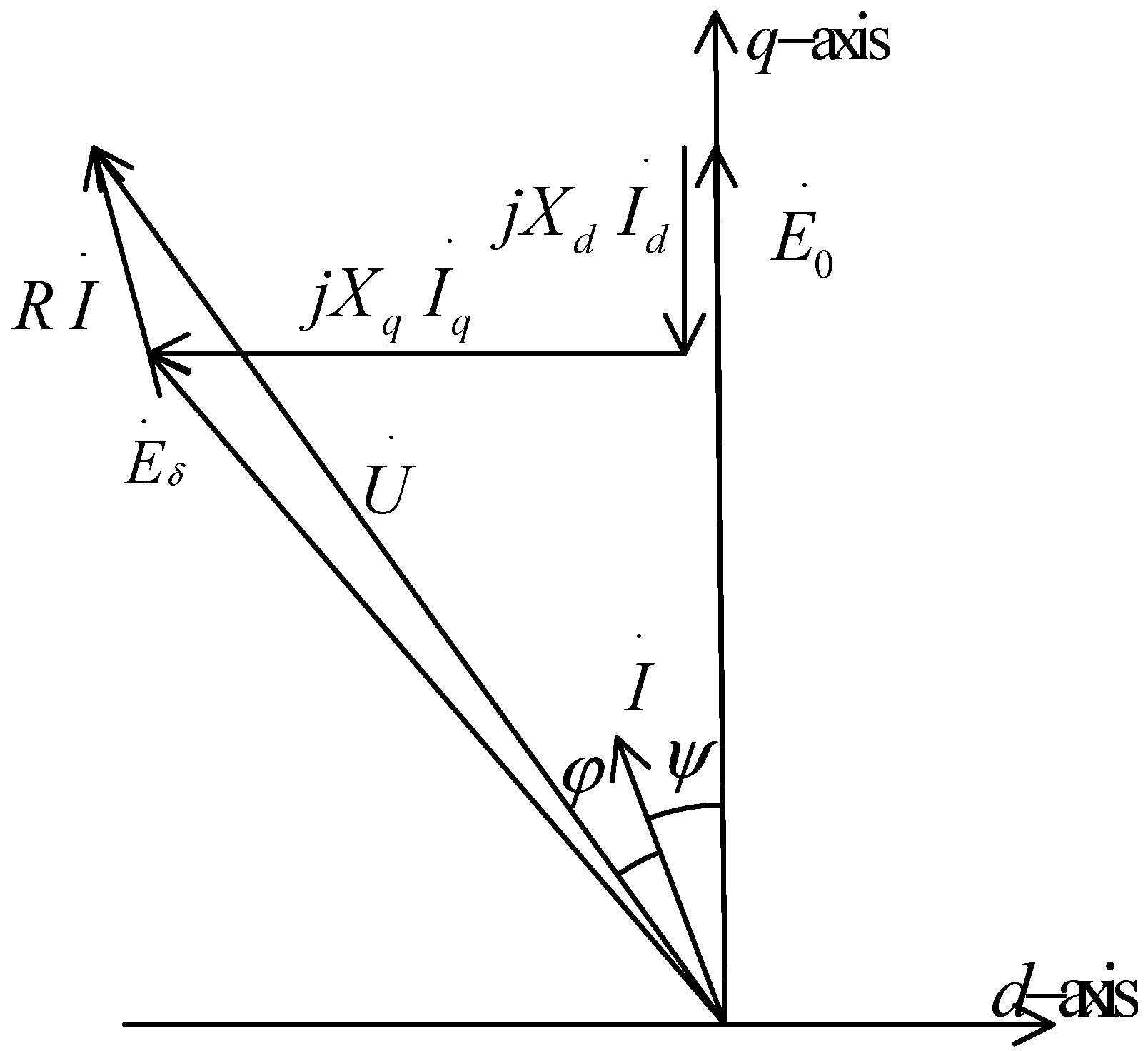
12]. This results from the special configuration of BDRM, which causes serious leakage flux in the magnetic circuit. A phasor diagram of the BDRM is shown in
Figure 6, where
E0 and
Eδ are the fundamental BEMF in no-load and load operation;
Id,
Iq are the d- and q-axis armature currents;
R1 is the armature resistance;
U is the voltage fed by external circuit;
Xd,
Xq are the d- and q-axis synchronous reactance and
φ is the power factor angle.
When
Id = 0, neglecting the small voltage drop across phase resistance, the power factor could be expressed as [
12]:
The no-load BEMF is proportional to the frequency, the number of coils and the main flux from the PM, and it could be expressed as:
where
k1 is the scale coefficient;
is the total main flux from the PM.
Figure 6.
Phasor diagram of the BDRM when Id ≠ 0.
Figure 6.
Phasor diagram of the BDRM when Id ≠ 0.
The
q-axis synchronous reactance is proportional to the frequency,
q-axis permeance, and the square of the numbers of coils, and it could be expressed as:
where
k2 is the scale coefficient;
is the main permeance;
is the leakage permeance;
is the leakage coefficient.
Bring Equations (7) and (8) into Equation (6), the power factor can be expressed as:
Equation (9) presents the basic factors affecting the power factor. When the main flux Φm from the PM is increased, the power factor will be increased. Moreover, when the number of coils or the armature current is increased, the power factor will be decreased.
The distribution of magnetic field caused by PM and stator windings is analyzed, respectively, and the best match ratio between them is obtained.
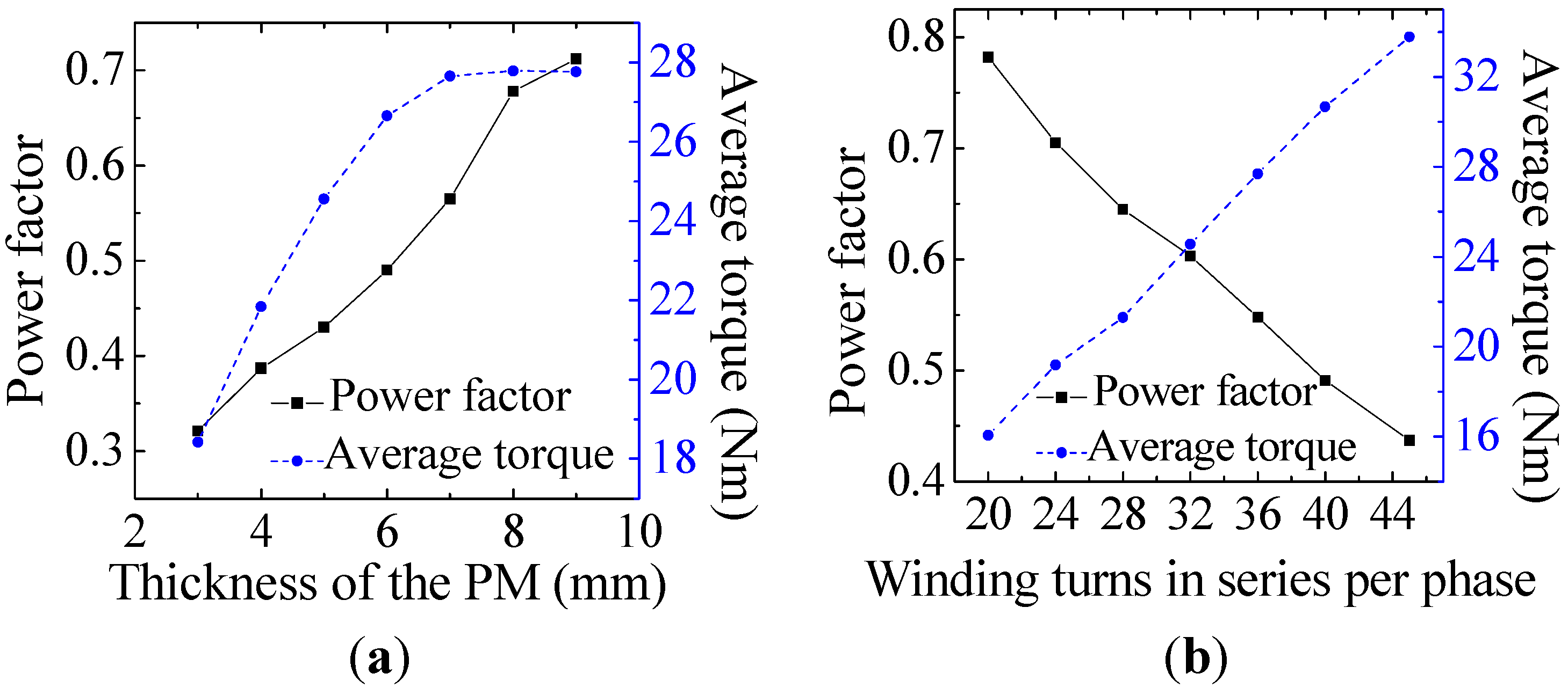
Figure 7 shows the variation of power factor and average torque
versus the amount of PM and winding turns. In
Figure 7, the average torque is obtained from the torque curve according to the FEM simulation. From
Figure 7, it could be concluded that increasing thickness of the PM is an efficient way to improve the power factor and enhance torque density at the same time.
Figure 7.
The parametric influences on power factor and average torque. (a) thickness of the PM; (b) winding turns in series per phase.
Figure 7.
The parametric influences on power factor and average torque. (a) thickness of the PM; (b) winding turns in series per phase.
Although decreasing the stator current will increase the power factor, the torque output will obviously fall at the same time [
13,
14], and this is clearly not attractive in practice. The effective approach is to change the phase of stator current. By using vector control method in the inverter, the phase angle of the stator current can be adjusted. According to the phasor diagram, neglecting the small voltage drop across phase resistance, the power factor angle could be expressed as:
Then the power factor could be expressed as:
where
Ld;
Lq are the
d- and
q-axis inductance;
ω is the radian frequency.
The angle
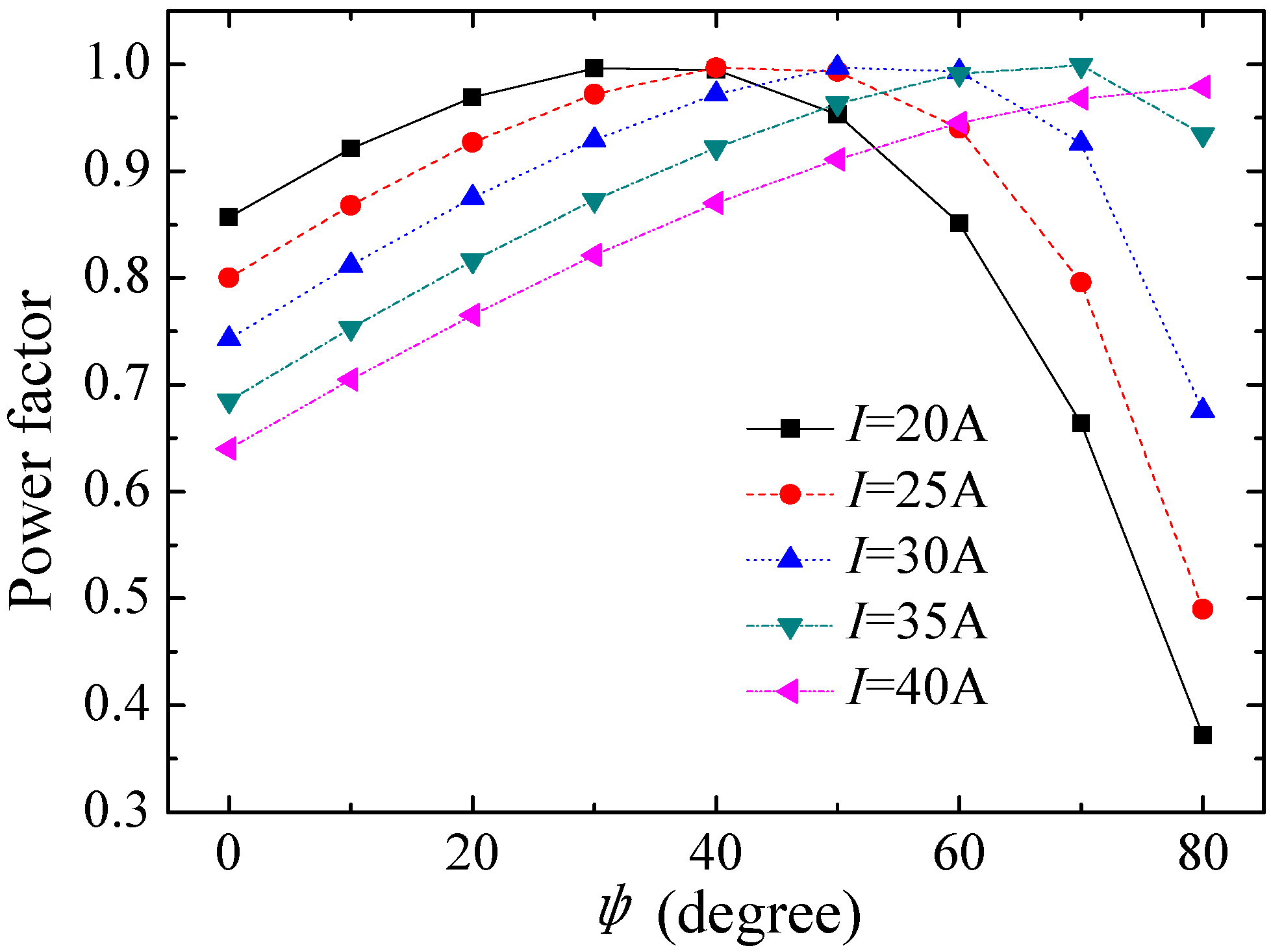
ψ depends on the phase angle of the input current from the inverter. It can be seen from Equation (11) that when the phase angle of the input current from the inverter is changed, different power factors will result. Under different amplitude and phase angle of stator current,
E0,
d-axis and q-axis inductance can be calculated by employing FEM, and then the power factor can be obtained from analytical calculation according to Equation (11). The variation of power factor
versus ψ is shown in
Figure 8. It can be seen that, for a fixed current value, the power factor will always reach its maximum value at a positive torque angle. Therefore, the power factor improvement can be realized by advancing the current phasor.
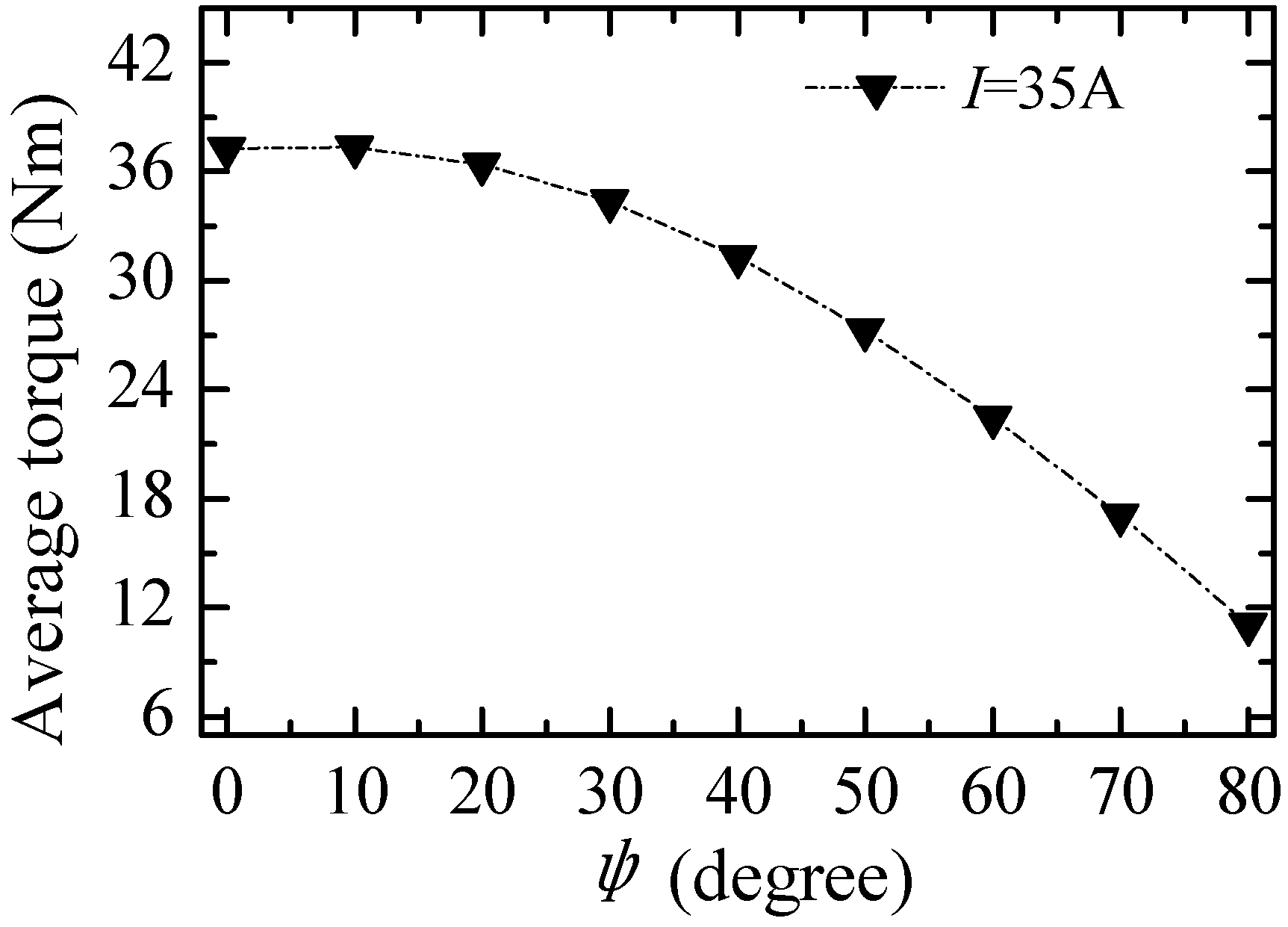
The average torque versus
ψ (
i.e., current angle leading the BEMF) is calculated when the rms value of the current is 35 A, as shown in
Figure 9. There is only a slight decrease of the average torque value with the increase of the inner power factor angle when the inner power factor angle is small (0°~20°), so when the flux weakening mode is used, the proportion of the d-axis current should not be too large.
Figure 8.
Variation of power factor versus ψ under different stator current conditions.
Figure 8.
Variation of power factor versus ψ under different stator current conditions.
Figure 9.
Torque versus ψ when rms value of the current is 35 A.
Figure 9.
Torque versus ψ when rms value of the current is 35 A.
5. Construction of the Prototype
A BDRM prototype dimensioned for 10 kW has been manufactured and its major geometrical parameters are listed in
Table 1.
Table 1.
Geometrical parameters of the BDRM prototype.
Table 1.
Geometrical parameters of the BDRM prototype.
| Parameters | Value | Parameters | Value |
|---|
| Phase number | 3 | Length of the PM (mm) | 66 |
| Pole-pair number | 6 | Width of the PM (mm) | 24 |
| Stator outer diameter (mm) | 200 | Thickness of the PM (mm) | 8 |
| Axial length of BDRM (mm) | 132 | Pole arc coefficient of the claw tip | 0.7 |
| Outer air gap length (mm) | 0.8 | Pole arc coefficient of the claw root | 0.7 |
| Inner air gap length (mm) | 0.8 | Thickness of the claw tip (mm) | 4.8 |
| Winding turns in series per phase | 46 | Thickness of the claw root (mm) | 15.4 |
| Number of slots | 3 | Shaft diameter of PM rotor (mm) | 48 |
The manufacturing process of the 3-phase stator is illustrated in
Figure 10. Each phase consists of laminated iron cores and one concentrated ring-shaped coil. An automatic winding machine is used to inlay the coils of stator winding into the coil slots. The results of the measurements show that a slot fill factor of about 0.78 is obtained.
Figure 10.
Manufacturing process of the 3-phase stator. (a) winding coils between the stator teeth; (b) installing the stator yoke.
Figure 10.
Manufacturing process of the 3-phase stator. (a) winding coils between the stator teeth; (b) installing the stator yoke.
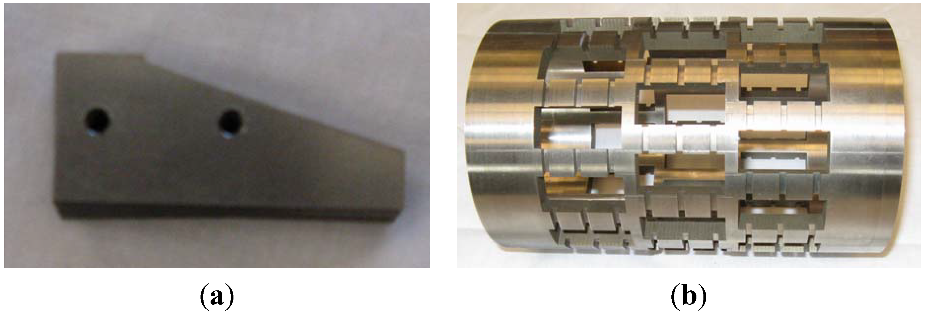
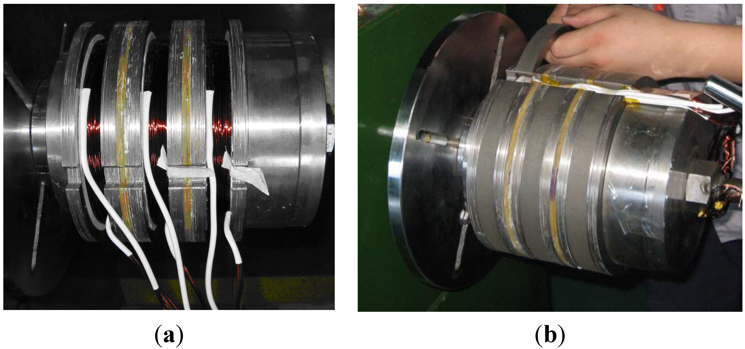
Difficulties were experienced in providing a tight fit between the claws and the non-magnetic bracket. A variety of methods have been tried and an effective solution obtained. As shown in
Figure 11a, the claws are built-up by silicon-iron laminations with two small holes. The hollow cylindrical bracket is made of non-magnetic stainless steel with several narrow slots on the surface as shown in
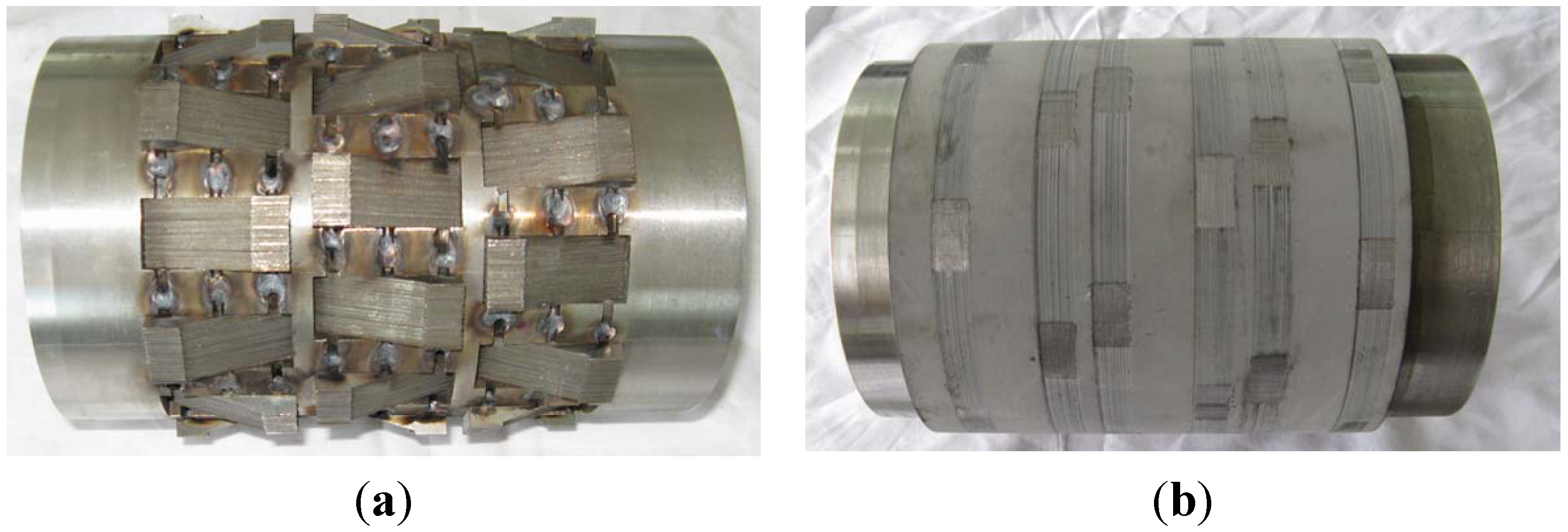
Figure 11b. The claws are firstly assembled by inserting a thin stainless steel rod into each hole, and then the claws are fixed on the non-magnetic bracket by welding these rods on the narrow slots. The assembled claw-pole rotor is shown in
Figure 12a, then it is further secured by means of epoxy resin casting as shown in
Figure 12b.
Figure 11.
Components of the claw-pole rotor: (a) the claws; (b) the non-magnetic bracket.
Figure 11.
Components of the claw-pole rotor: (a) the claws; (b) the non-magnetic bracket.
According to previous studies, the permanent-magnet rotor uses the tangential embedding rotor structure [
15]. This structure can achieve the effect of flux-concentration, which can effectively improve the torque density of the BDRM. The magnets are grade N40 sintered NdFeB PMs and are rectangularly shaped with dimensions: 66 mm × 24 mm × 8 mm.
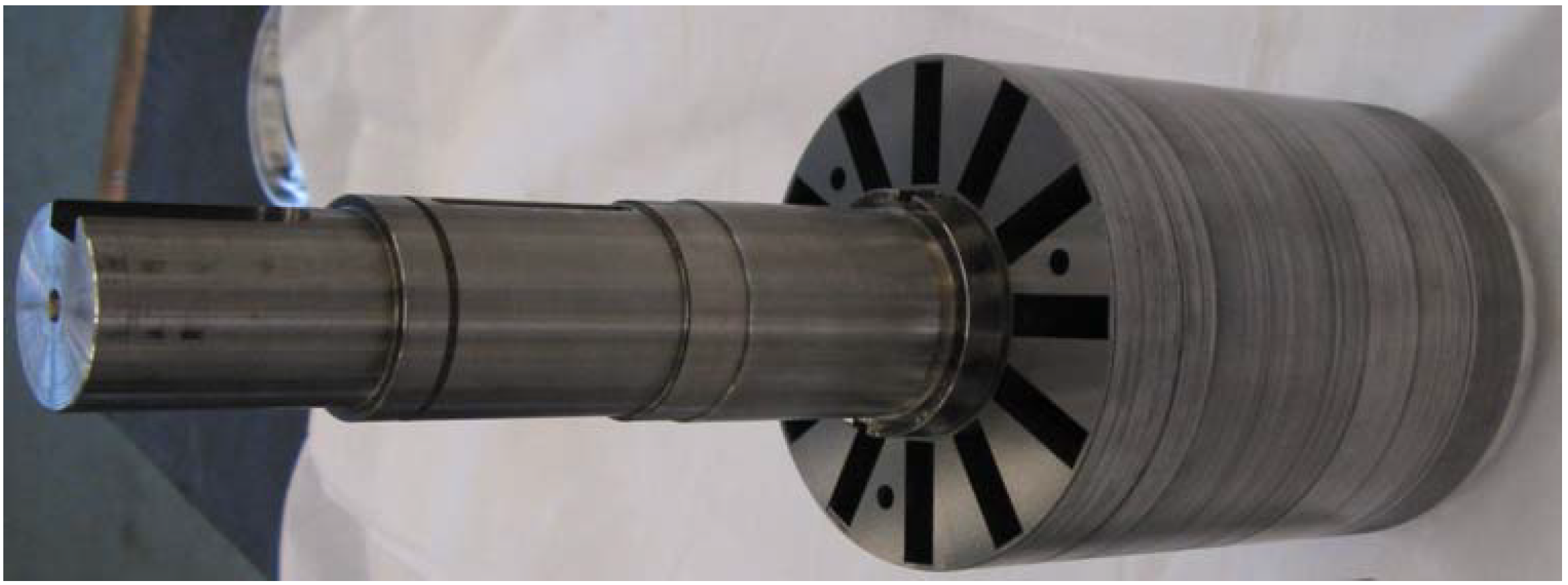
Figure 13 shows the assembled rotor core before the PMs are installed.
Figure 12.
Claw-pole rotor (a) before epoxy resin casting; (b) after epoxy resin casting.
Figure 12.
Claw-pole rotor (a) before epoxy resin casting; (b) after epoxy resin casting.
Figure 13.
Permanent-magnet rotor core.
Figure 13.
Permanent-magnet rotor core.
6. Performance of the Prototype
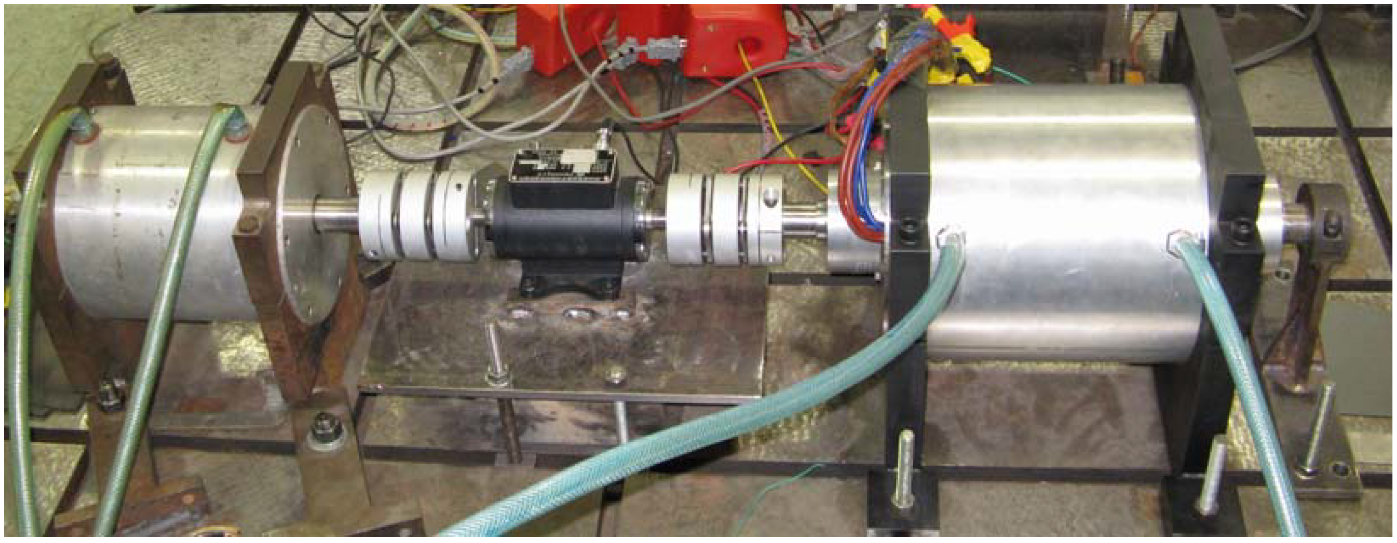
Some measurements were performed upon the prototype. In the first step of the measurements, the BDRM is tested as a conventional single-rotor machine, and in the second step, the BDRM will be tested by connecting two machines on both two rotors to simulate the operation modes of the HEV system. The test bench of the first step is shown in
Figure 14. The permanent-magnet rotor is connected with a synchronous machine on the left side, and the claw-pole rotor is fixed by a snap ring on the right side.
Figure 14.
Test bench of the BDRM.
Figure 14.
Test bench of the BDRM.
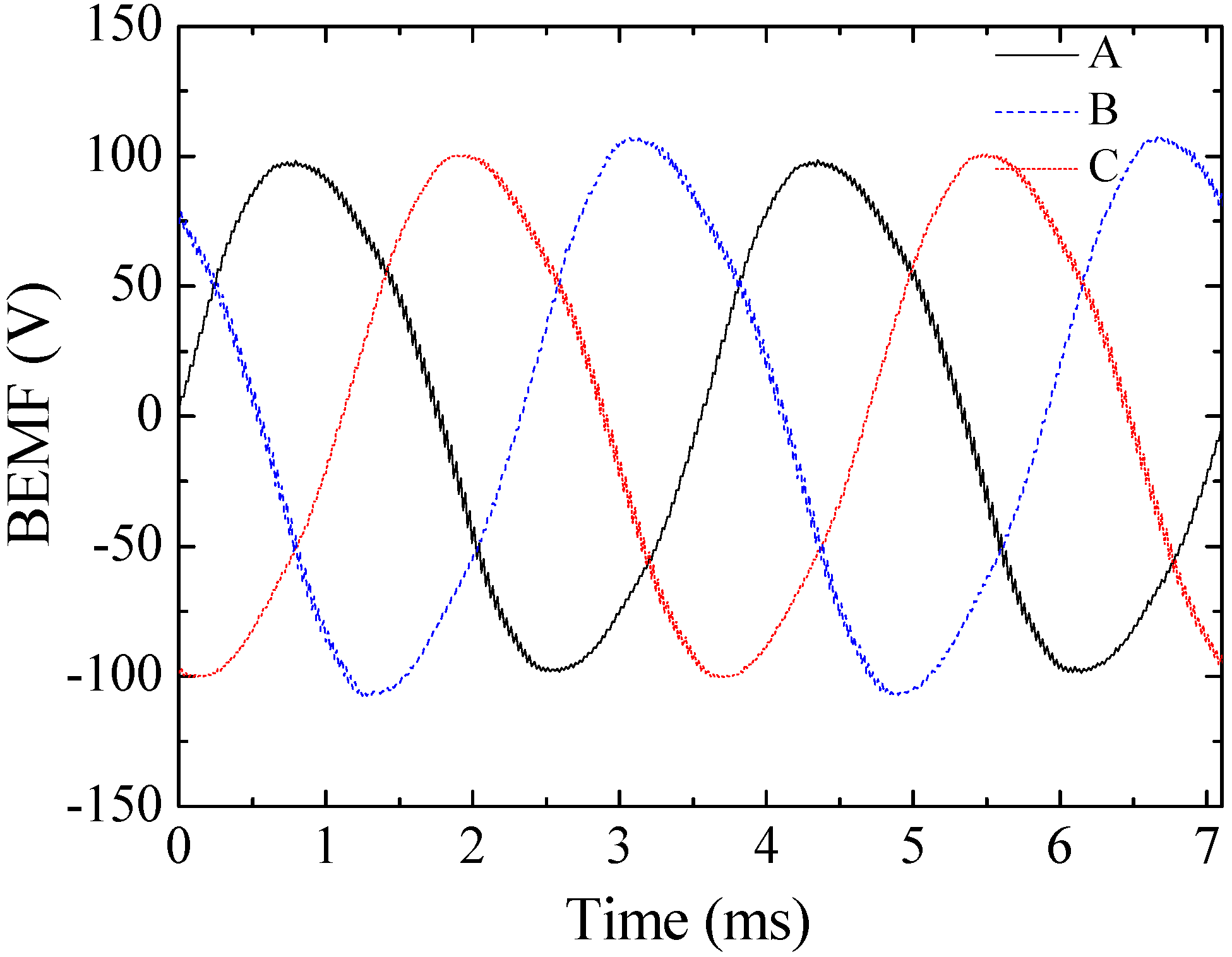
The tested no-load phase BEMFs at a rated speed of 2800 rpm are shown in
Figure 15. Due to the end effect, the BEMF of B-phase is a little higher than those of the other two phases. The low harmonic content is apparent from the sinusoidal shape of the waveforms.
Figure 15.
Tested no-load phase BEMFs at rated speed of 2800 rpm.
Figure 15.
Tested no-load phase BEMFs at rated speed of 2800 rpm.
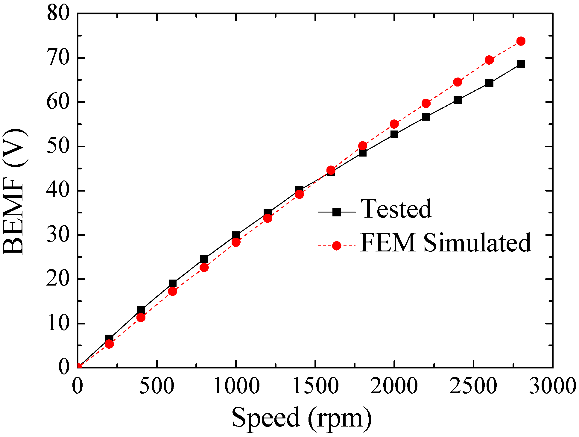
Tested and simulated no-load A-phase BEMFs at different speeds are compared in
Figure 16. It can be seen that the tested and simulated rms values are in good agreement.
Figure 16.
Tested and simulated no-load A-phase BEMFs at different speeds.
Figure 16.
Tested and simulated no-load A-phase BEMFs at different speeds.
The accurate measurement of cogging torque and torque ripple is helpful in performance evaluation and further optimization of the BDRM. The cogging torque values between permanent magnetic rotor and the claw pole rotor is shown in
Table 2. It can be seen that tested peak-peak value of cogging torque is about 1.9 Nm, which is higher than conventional PM machines.
Table 2.
Tested and simulated cogging torque between PM rotor and claw pole rotor.
Table 2.
Tested and simulated cogging torque between PM rotor and claw pole rotor.
| Torque | Tested | Simulated |
|---|
| Peak-peak value of cogging torque (Nm) | 1.9 | 2.1 |
| Periodic numbers of cogging torque in one cycle | 12 | 12 |
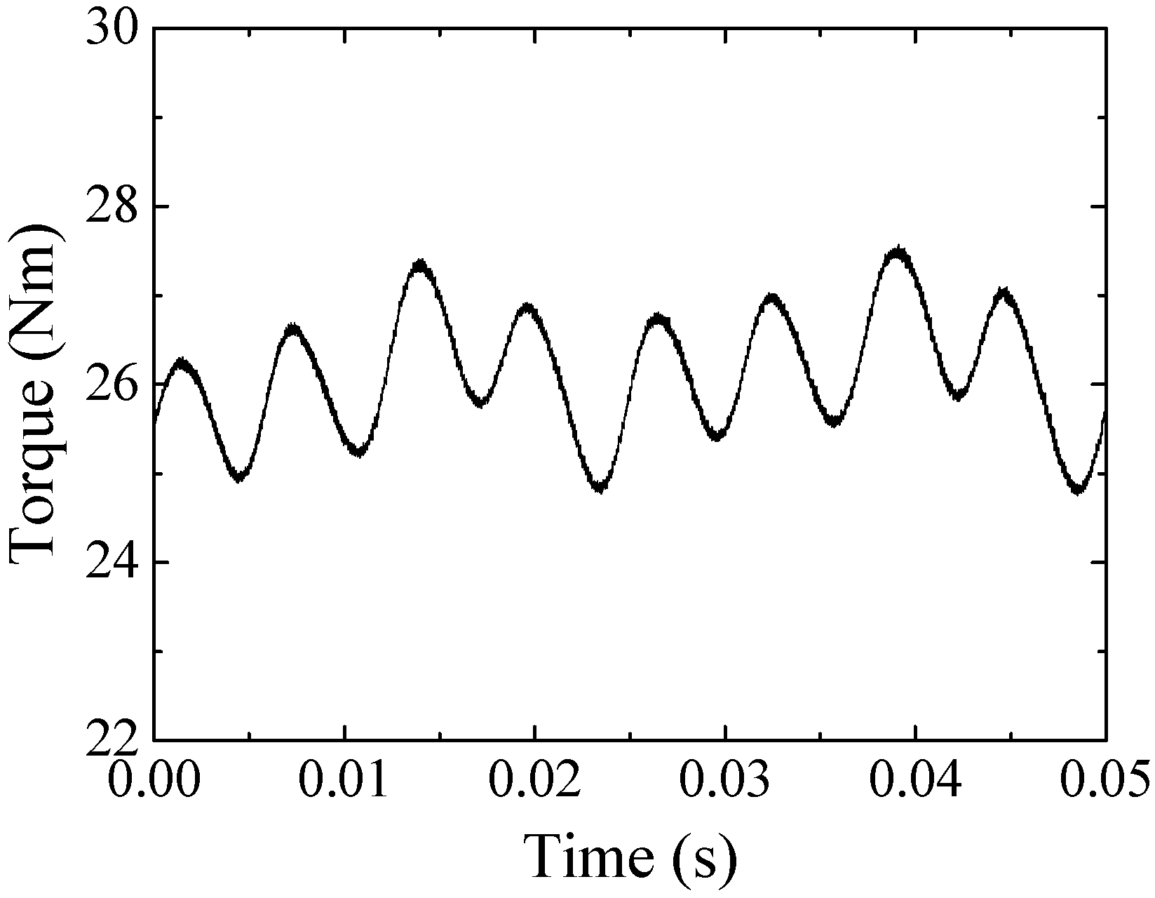
The load torque is tested at the speed of 800 rpm, as shown in
Figure 17. The average torque is 26.1 Nm and the torque ripple is about 5.4%, which is also higher than that of conventional PM machines. The high cogging torque and torque ripple are mainly caused by the large air gaps between the claws. As torque ripple of the ICE is much higher than electric machines, torque ripple of the BDRM is considered acceptable for HEV applications.
Figure 17.
Tested load torque at the speed of 800 rpm.
Figure 17.
Tested load torque at the speed of 800 rpm.
Furthermore, the no-load loss has been measured. In no-load tests, two rotors of the prototype are dragged to rotate at different speeds. Then the no-load loss is the difference of the mechanical power measured from the two shafts:
where
Ps1,
Ps2 are the mechanical power measured from the two shafts;
Pfw is the no-load loss of the BDRM.
During the test, it is found that torque of the two shafts is basically the same, so the no-load torque of the BDRM can be measured from either of the two shafts. Then the equation of the no-load loss can be represented as:
where
Ωs1,
Ωs2 are the mechanical speed of the two shafts; and
T is the no-load torque of the BDRM.
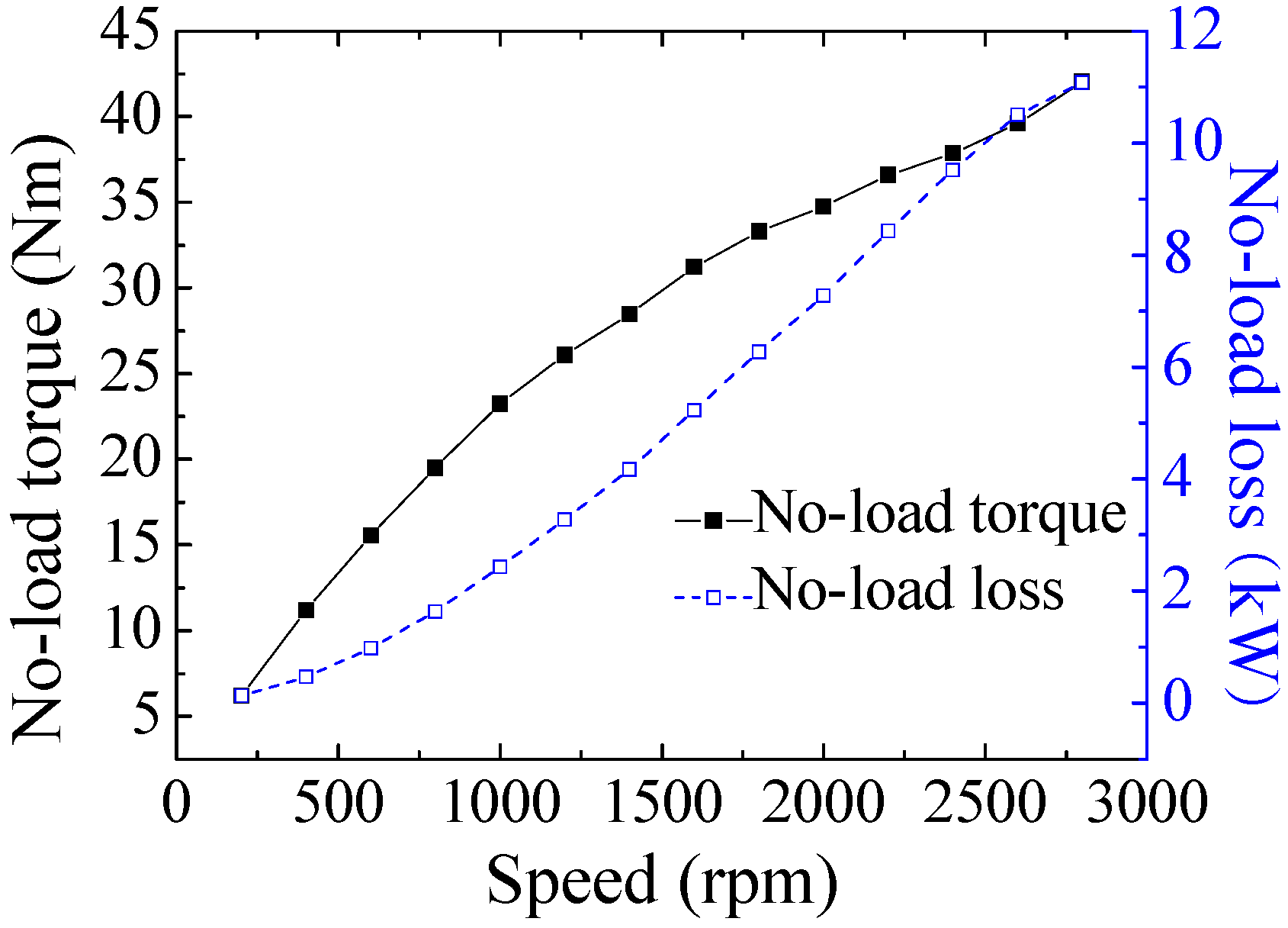
The loss is investigated when the machine is operating in generator mode up to rated speed. However, a considerable braking torque is detected and the no-load loss is extremely high as shown in
Figure 18.
Figure 18.
Variation of average torque and no-load loss versus the shaft speed.
Figure 18.
Variation of average torque and no-load loss versus the shaft speed.
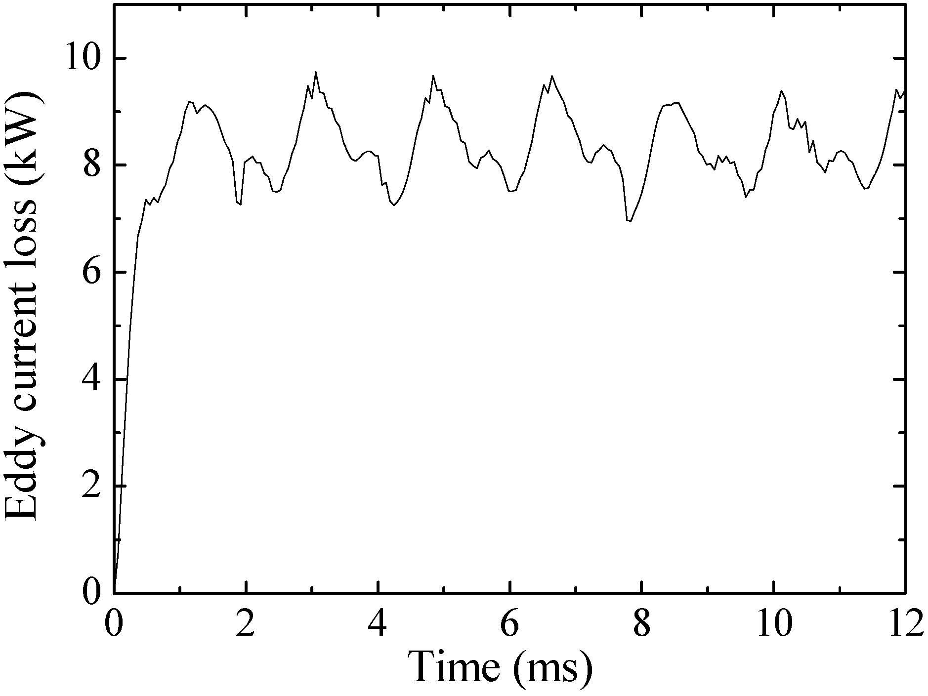
An investigation led to the identification of one manufacturing defect mainly related to this phenomenon. This is the existence of a conductive bracket in the claw-pole rotor. The eddy current loss of the bracket has been estimated with the aid of 3D FEM simulation [
16,
17]. As shown in
Figure 19, the eddy current loss is approximately 8 kW at rated speed, and this could contribute up to 73% of the whole loss. Simulation results verified that even if the bracket is built using a non-magnetic metrical, its conductive properties will result in significant eddy current loss.
Figure 19.
Simulated eddy current loss of the bracket at rated speed.
Figure 19.
Simulated eddy current loss of the bracket at rated speed.
The bracket fault has unfortunately delayed the test program, so there are no results from tests of the BDRM in different HEV operation modes to be presented in this paper. The improvement of the prototype will be undertaken and disseminated in future publications.


