The primary target of the Top Layer is to ensure voltage security and stability in the power system as well as to improve the dynamic quality of voltage. In the Top Layer, discrete events are constructed to drive the control. Meanwhile, coordination among various voltage control components is taken into consideration in this layer.
3.1. Dynamic Voltage Stability Analysis Method
When analyzing the system dynamic voltage security and stability, the control interval is relatively longer with the system status changing slowly. Therefore linearized differential-algebraic-equations (DAE) are used to describe the power system’s dynamics. Through analyzing the eigenvalue of the relevant DAE system, judgment is made regarding the stability of the power system.
Since the dynamic performance of generators and induction motors in power system are described by differential equations f(x,y,u) and the power grid is supposed to meeting the constraints of power flow algebraic equations g(x,y,u), the power system can be described by differential-algebraic-equations [
8,
9] as follows:
where x denotes the dynamic variables such as rotor angel and angular velocity of generators; y denotes the algebraic variables like voltage and angle of each bus in power system; and u denotes the controlling variables like generator excitation output in this paper. By linearizing the above system in expression Equation (1) at the operating point, we get the following equation:
where J, B and C can be referred to as in literature [
7].
Through linearization, we have acquired the linear differential equations in Equation (2) which describe the dynamic process of the power system. Based on the linear differential equations, we can analyze the stability of the system through the eigenvalues of the coefficient matrix. The most common solution for an eigenvalue is the QR method [
8], but the matrix dimension limits the application of conventional QR methods. Generally speaking, conventional QR methods can only help acquire eigenvalues of matrixes of less than 200 ranks. However, in reality hundreds of generators and loads run in large-scale power systems, therefore QR methods are no longer applicable, and order reduction of the original system needs to be accomplished before the iteration method can be applied [
8].
3.2. Analysis of Minimum Amplitude Eigenvalue
As the minimum amplitude eigenvalue (MAE) is acquired through the above steps, the stability status of the power system can be judged by MAE’s amplitude, and the discrete variables are formed and sent to the discrete control blocks. Furthermore we define the following mapping:
where
λmin[
k] denotes the MAE calculated at the end of the
k-th control interval;
λDP[
k] denotes the discrete variable, as well as the input of the subsequent discrete control.
λDP[
k] is valued by the following rules:
where
λsafe denotes the pre-set minimum security value;
λalert denotes the pre-set alert value.
In addition to using the MAE index, we can also use other kinds of voltage stability indexes, which can be easily improved for use in the proposed HD-AVC system.
3.3. Events and Control for Voltage Stability
As the amplitude of MAE,
λmin[
k] is acquired. It is sent together with the status-discrete value of pilot buses [
7] to the discrete control blocks and form discrete events. Thus we can come to the control output.
The input-output characteristics of the discrete control block are defined as follows:
where the parameter
k stands for after
k control intervals;
EDE and
ODE refer to status transmitting function and output function of the discrete control block respectively;
xDE[
k] and
uD[
k] denote status variables and output events of the control block respectively;
xDP[
k] refers to the status discrete magnitude;
xH[
k] is the output of the Top Layer at interval (
k − 1), as following:
As shown in Equation (5), the status transmitting function
EDE transforms the discrete magnitude representing system security and stability together with the discrete magnitude representing status of the pilot buses into discrete events, and the discrete events drive the output of discrete control. Three “events” are defined as follows:
where
Pimp,
Pacc and
Pbad stand for sound, ordinary and poor quality of voltage control. In order to get the status transmitting function
EDE, the temporary variables
xvol[
k],
xdec[
k] and
xinc[
k] are defined as follows:
where
αP refers to the number of pilot buses, and:
x1i[
k] = {1, 0, −1} voltage status of pilot buses
i;
x2i[
k] = {1, 0, −1} voltage decrease speed rate status of pilot buses
i;
x3i[
k] = {1, 0, −1} voltage increase speed rate status of pilot buses
i.
For the above variables, a value of 1, 0, −1 means the corresponding plant status is acceptable, inadequate or undesirable, respectively. The criteria of the acceptable, inadequate and undesirable statuses are decided by the designer, and with the different power systems, the criteria are different. In this paper, the three statuses are defined as follows:
where
εji(
j = 1, …, 6) are the setting boundary values of pilot bus
i,
is the setting ideal voltage value of pilot bus
i. The above boundary values and the voltage value are not set by unified and fixed rules, and they can be set differently according to the specific circumstances in power system. Finally, the logic rules to form discrete “events” are defined as follows:
The logic rules of the above discrete events are not fixed, and can be modified according to the system’s specific conditions.
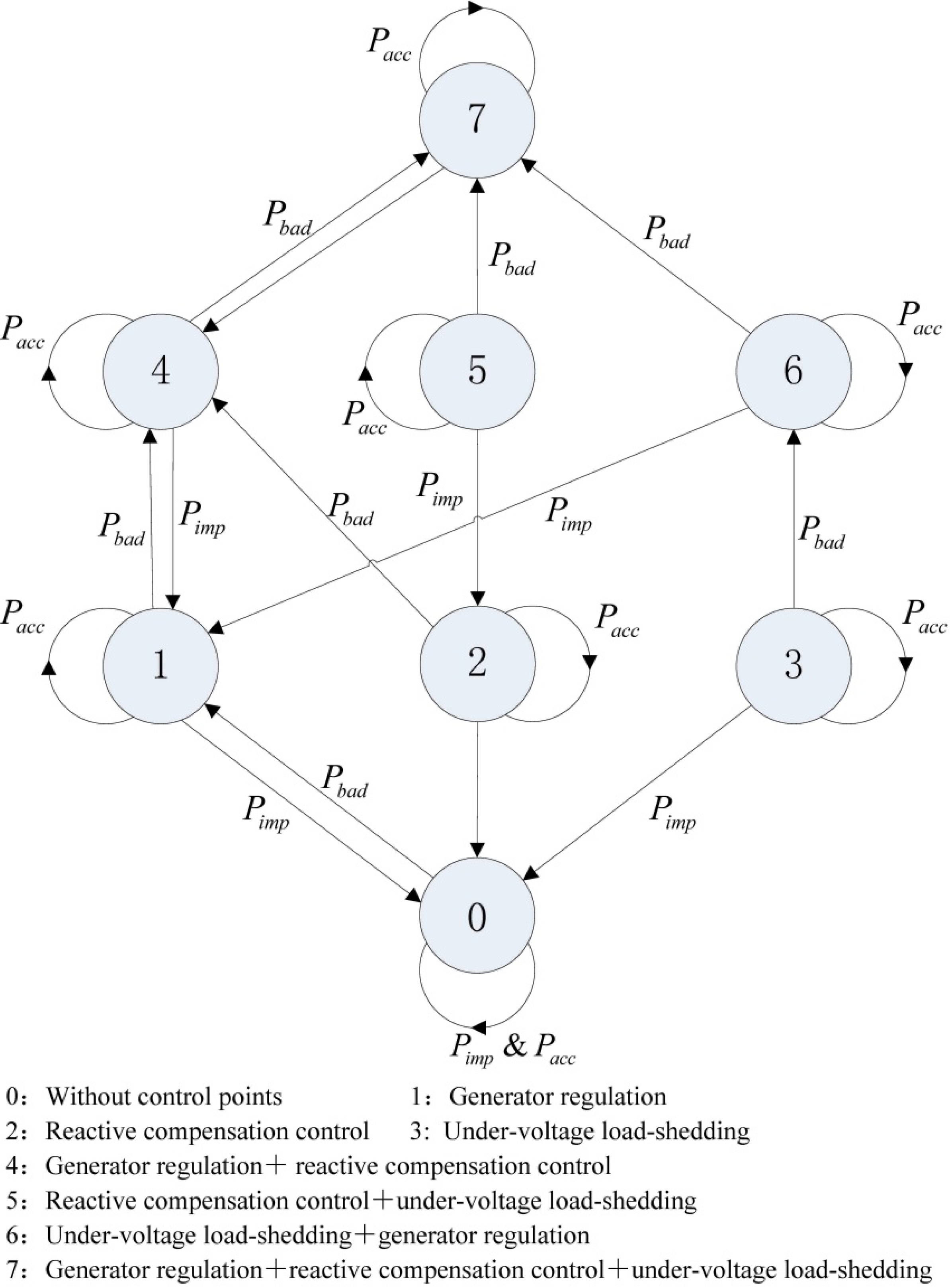
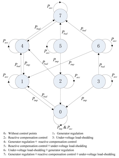
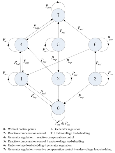
The output function
QDE(·) in Equation (5) is shown in
Figure 2, where the arrow indicates that due to the emergence of discrete events
xDE[
k], the control output shifts from that in the last interval
xH[
k] to the present interval
uD[
k]. As defined below:
The implication of the numbers in Equation (10) is shown in
Figure 2. As an illustration,
Figure 2 shows that no path is available to convert from 2 to 0, from 3 to 0, from 6 to 3, from 7 to 5 and from 7 to 6. This is designed so as to minimize the system operation cost, prolong service lifetime of reactive compensation equipment and minimize users’ losses. Among power system’s control measures, generator regulation is given top priority, followed by reactive power compensation control, while load-shedding is the last choice.
Figure 2.
Discrete output function in the top layer.
Figure 2.
Discrete output function in the top layer.
3.4. Man-Machine Interface Block
After the discrete control block, we defined a Man-Machine Interface Block, which can accept the system dispatchers’ control commands. The supreme authority is given to the dispatchers’ control commands in the interface block. By the following mapping
Tu, we can get the Top Layer’s control output:
where
xu[
k]= [
uuser[
k],
uD[
k]]
T and
uuser[
k] ∈ {0, 1, 2, 3, 4, 5, 6, 7, 8}. The values of 0 to 7 have the same meaning of
uD[
k], and 8 represents that theydo not have any dispatcher control command input. We define the output of Man-Machine Interface Block as below:
where
uH[
k] ∈ {0, 1, 2, 3, 4, 5, 6, 7}, and the values of 0 to 7 have the same meaning of
uD[
k].
