Hydrate Formation/Dissociation in (Natural Gas + Water + Diesel Oil) Emulsion Systems

Abstract
:1. Introduction
2. Experimental
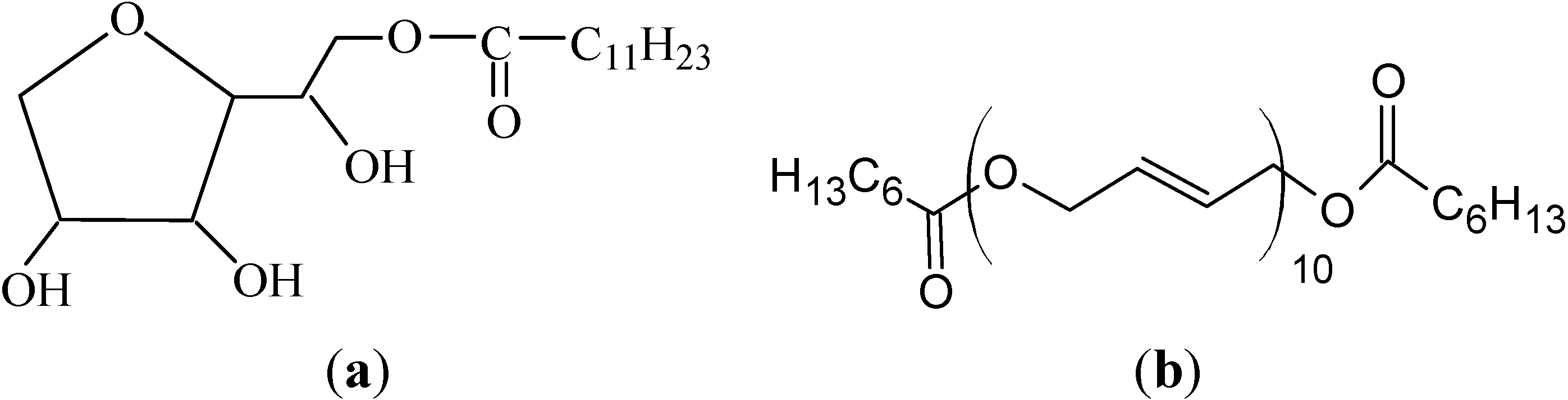
2.1. Materials

| Component | mol% | wt% | |
|---|---|---|---|
| C7 | Heptanes | 0.22 | 0.10 |
| C8 | Octanes | 1.35 | 0.70 |
| C9 | Nonanes | 3.60 | 2.09 |
| C10 | Decanes | 3.70 | 2.39 |
| C11 | Undecanes | 5.90 | 4.19 |
| C12 | Dodecanes | 5.16 | 3.99 |
| C13 | Tridecanes | 8.34 | 6.98 |
| C14 | Tetradecanes | 13.60 | 12.25 |
| C15 | Pentadecanes | 11.37 | 10.97 |
| C16 | Hexadecanes | 10.08 | 10.37 |
| C17 | Heptadecanes | 9.59 | 10.47 |
| C18 | Octadecanes | 8.71 | 10.07 |
| C20 | Eicosanes | 11.42 | 14.66 |
| C24 | Tetracosanes | 6.81 | 10.47 |
| C28+ | Octacosanes plus | 0.15 | 0.30 |
| - | Total | 100.00 | 100.00 |
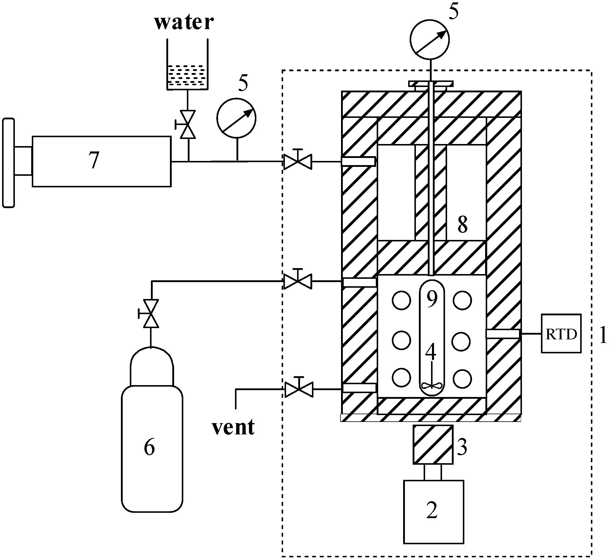
2.2. Apparatus and Procedures
3. Results and Discussion
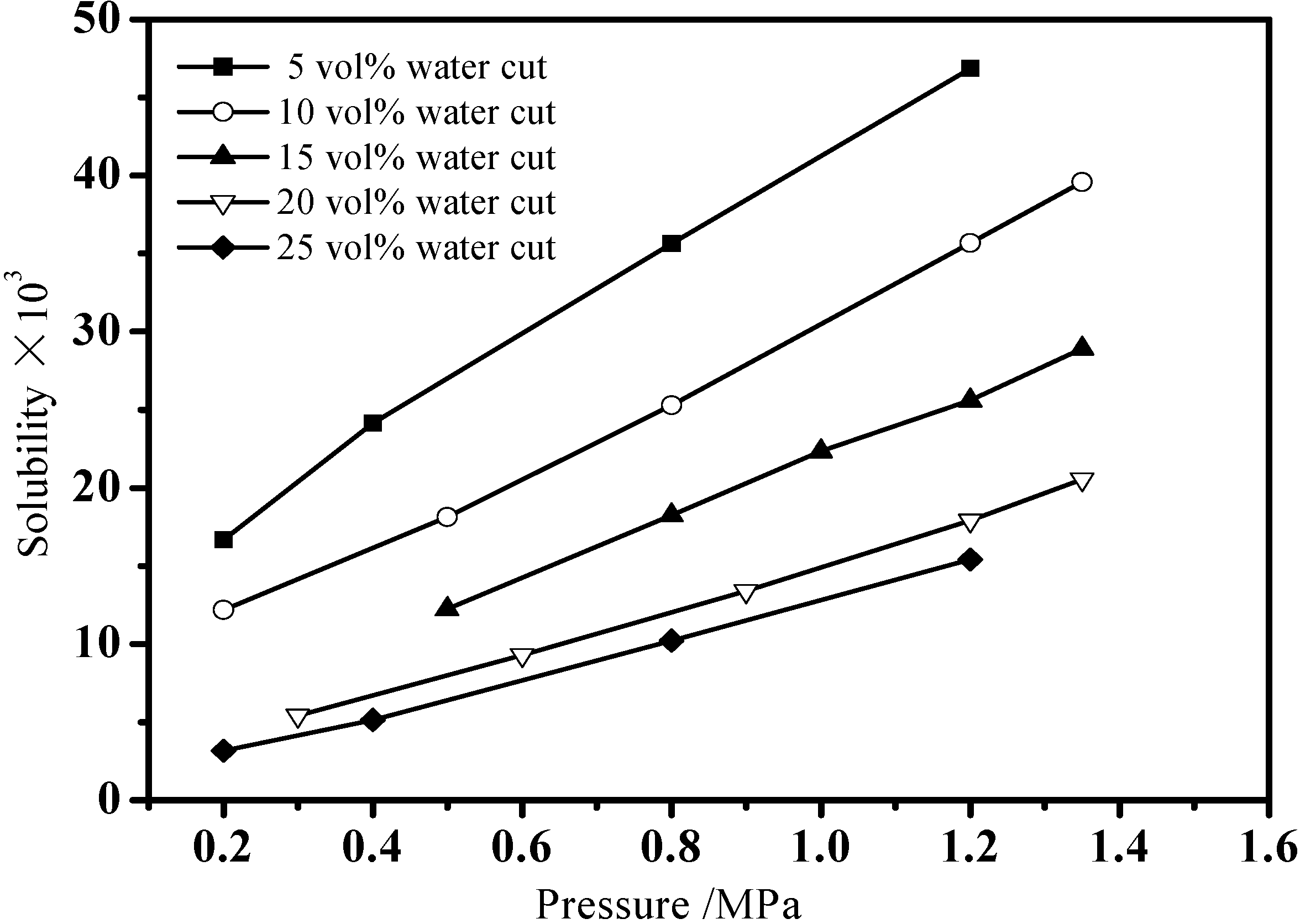
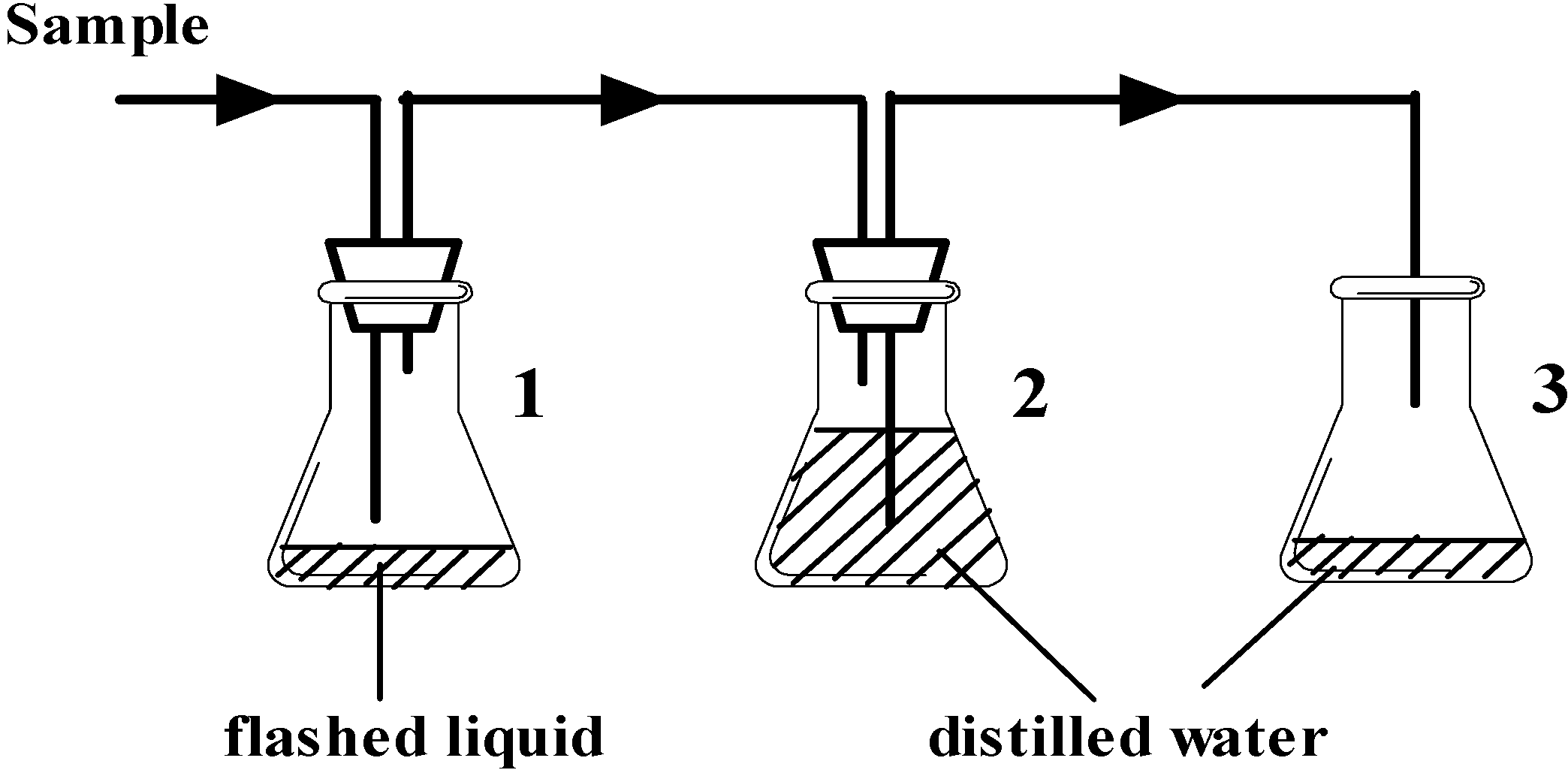
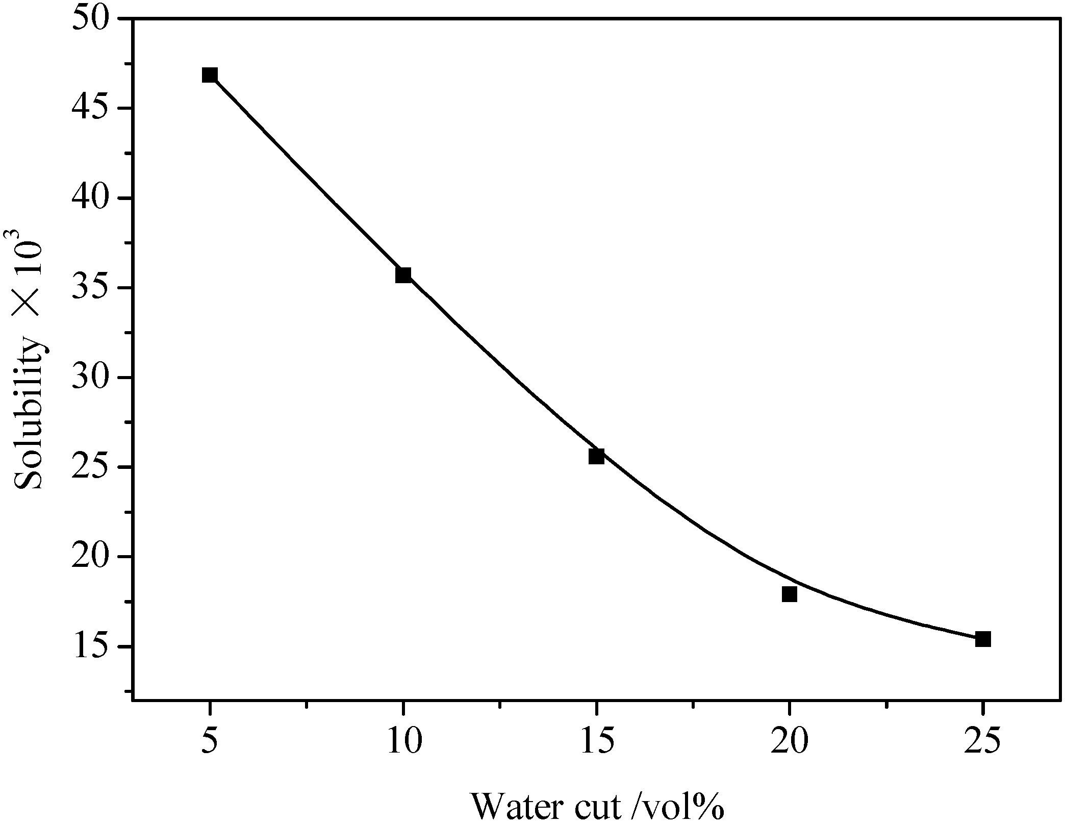
3.1. Gas Solubility in Emulsion
| 5 vol% water cut | 10 vol% water cut | 15 vol% water cut | 20 vol% water cut | 25 vol% water cut | |||||
|---|---|---|---|---|---|---|---|---|---|
| P (MPa) | s (×103) | P (MPa) | s (×103) | P (MPa) | s (×103) | P (MPa) | s (×103) | P (MPa) | s (×103) |
| 0.2 | 16.68 | 0.2 | 12.20 | 0.5 | 12.25 | 0.3 | 5.43 | 0.2 | 3.16 |
| 0.4 | 24.15 | 0.5 | 18.12 | 0.8 | 18.25 | 0.6 | 9.30 | 0.4 | 5.13 |
| 0.8 | 35.65 | 0.8 | 25.29 | 1.0 | 22.35 | 0.9 | 13.39 | 0.8 | 10.21 |
| 1.2 | 46.86 | 1.2 | 35.69 | 1.2 | 25.59 | 1.2 | 17.93 | 1.2 | 15.42 |
| - | - | 1.35 | 39.59 | 1.35 | 28.92 | 1.35 | 20.56 | - | - |

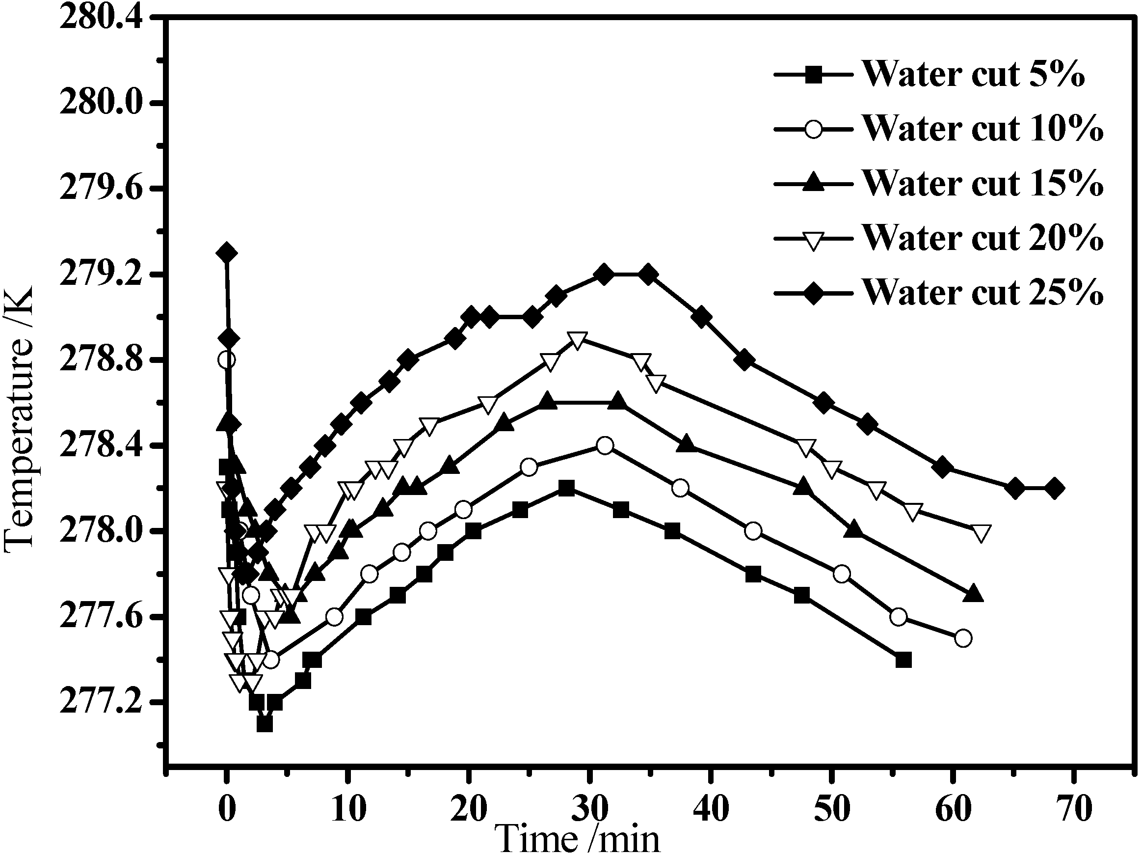
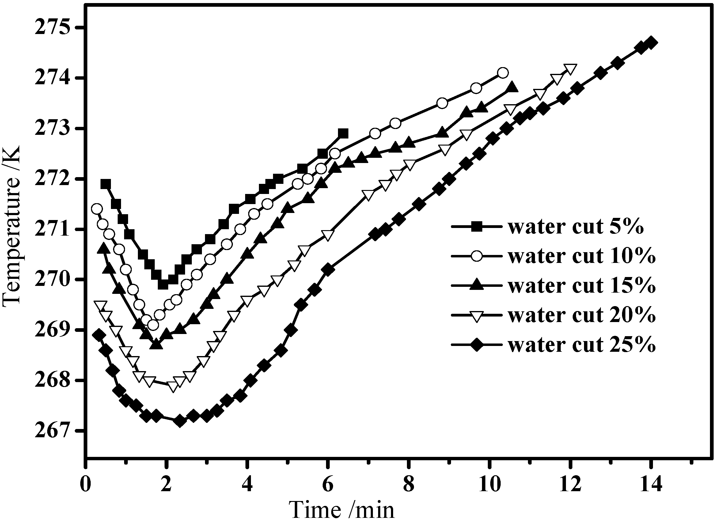
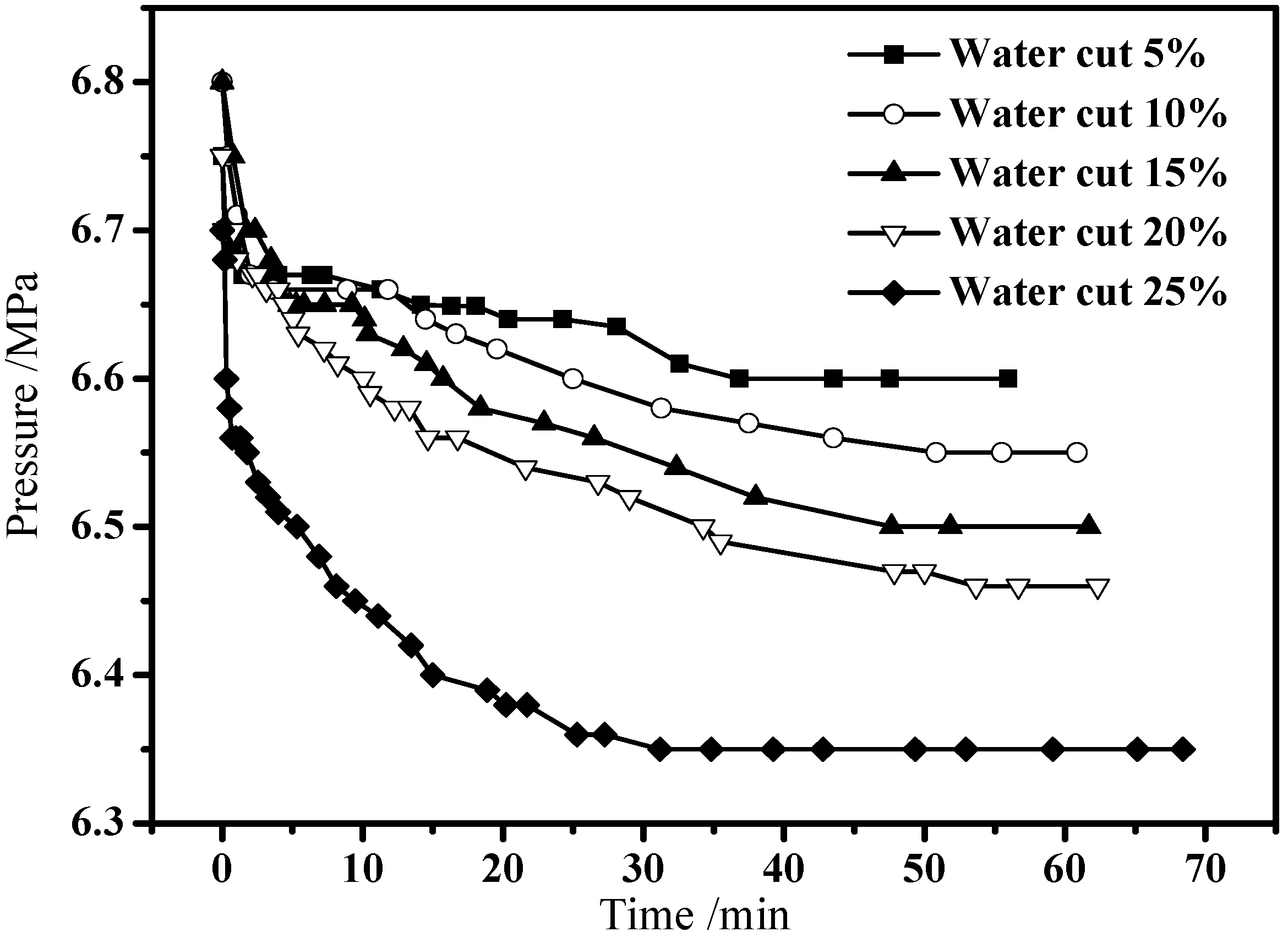
3.2. Hydrate Formation in Emulsion Systems

| Water cut | Fraction (mol%) | |||||||
|---|---|---|---|---|---|---|---|---|
| CO2 | N2 | CH4 | C2H6 | C3H8 | i-C4 | n-C4 | C6 | |
| 5 wt% | 6.51 | 18.56 | 72.63 | 0.51 | 0.49 | 0.81 | 0.24 | 0.25 |
| 10 wt% | 6.28 | 18.99 | 73.17 | 0.33 | 0.25 | 0.59 | 0.19 | 0.19 |
| 15 wt% | 6.15 | 19.24 | 73.42 | 0.25 | 0.18 | 0.48 | 0.14 | 0.14 |
| 20 wt% | 6.06 | 19.28 | 73.59 | 0.22 | 0.15 | 0.44 | 0.14 | 0.12 |
| 25 wt% | 5.87 | 19.32 | 73.83 | 0.19 | 0.15 | 0.44 | 0.13 | 0.07 |

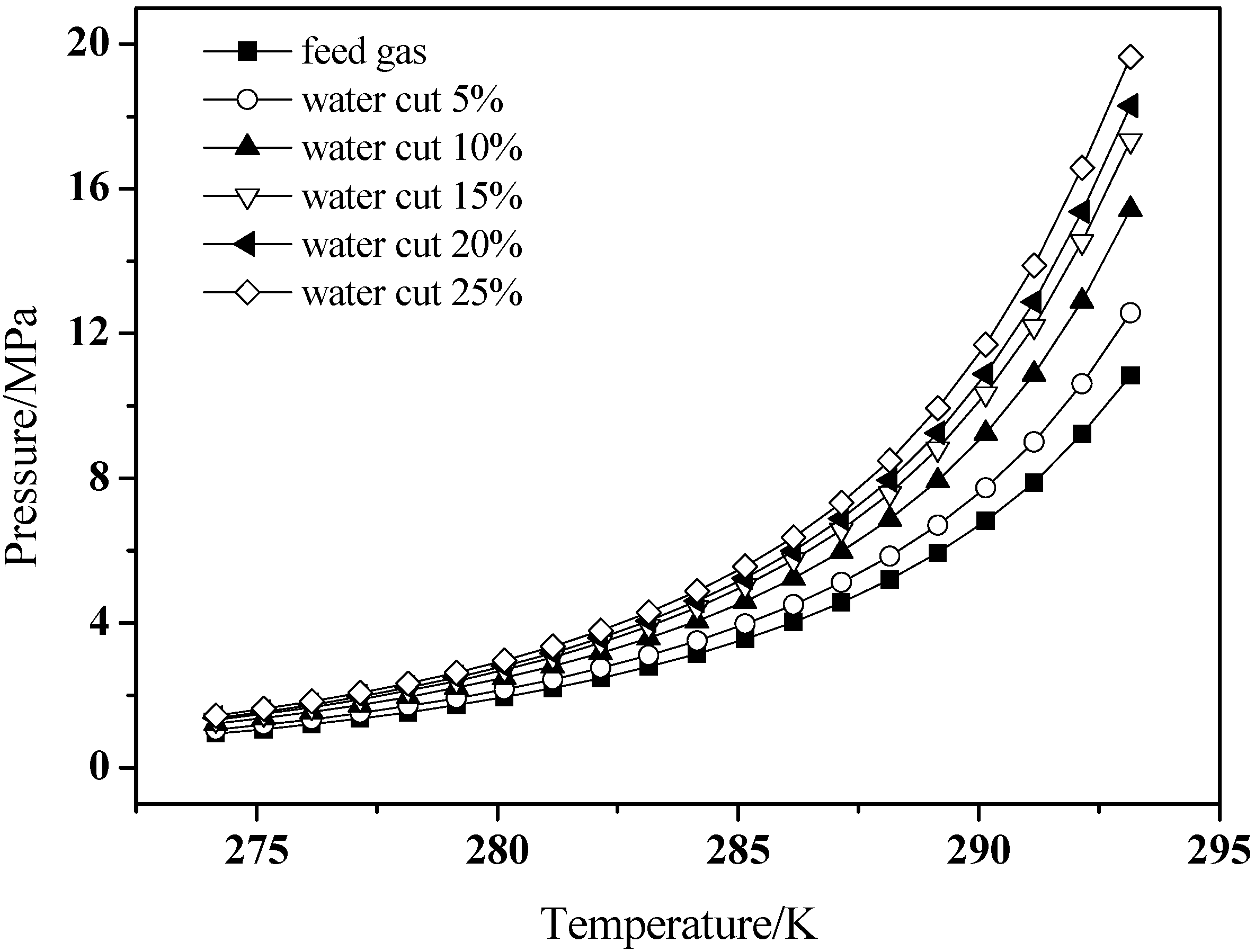
3.3. Hydrate Dissociation in Emulsion Systems


4. Conclusions
Acknowledgments
References
- Huo, Z.; Freer, E.; Lamar, M.; Sannigrahi, B.; Knauss, D.M.; Sloan, E.D. Hydrate plug prevention by anti-agglomeration. Chem. Eng. Sci. 2001, 56, 4979–4991. [Google Scholar]
- Arjmandi, M.; Tohidi, G.; Danesh, A.; Todd, A.C. Is subcooling the right driving force for testing low-dosage hydrate inhibitors. Chem. Eng. Sci. 2005, 60, 1313–1321. [Google Scholar] [CrossRef]
- Zanota, M.L.; Dicharry, C.; Graciaa, A. Hydrate plug prevention by quaternary ammonium. Energy Fuels 2005, 19, 584–590. [Google Scholar] [CrossRef]
- Kelland, M.A. History of the development of low dosage hydrate inhibitors. Energy Fuels 2006, 20, 825–847. [Google Scholar] [CrossRef]
- Zhang, L.W.; Chen, G.J.; Sun, C.Y.; Fan, S.S.; Ding, Y.M.; Wang, X.L.; Yang, L.Y. The partition coefficients of ethylene between hydrate and vapor for methane + ethylene + water and methane + ethylene + SDS + water system. Chem. Eng. Sci. 2005, 60, 5356–5362. [Google Scholar] [CrossRef]
- Sun, C.Y.; Ma, C.F.; Chen, G.J.; Zhang, S.X. Experimental and simulation of single equilibrium stage separation of (methane + hydrogen) mixtures via forming hydrate. Fluid Phase Equlib. 2007, 261, 85–91. [Google Scholar] [CrossRef]
- Marinhas, S.; Delahaye, A.; Fournaison, L. Solid fraction modeling for CO2 and CO2-THF hydrate slurries used as secondary refrigerants. Int. J. Refrig. 2007, 30, 758–766. [Google Scholar] [CrossRef]
- Wang, W.C.; Fan, S.S.; Liang, D.Q.; Yang, X.Y. Experimental study on flow characters of CH3CCl2F hydrate slurry. Int. J. Refrig. 2008, 31, 371–378. [Google Scholar] [CrossRef]
- Zhao, J.F.; Cheng, C.X.; Song, Y.C.; Liu, W.G.; Liu, Y.; Xue, K.H.; Zhu, Z.H.; Yang, Z.; Wang, D.Y.; Yang, M.J. Heat transfer analysis of methane hydrate sediment dissociation in a closed reactor by a thermal method. Energies 2012, 5, 1292–1308. [Google Scholar] [CrossRef]
- Xiong, L.J.; Li, X.S.; Wang, Y.; Xu, C.G. Experimental study on methane hydrate dissociation by depressurization in porous sediments. Energies 2012, 5, 518–530. [Google Scholar] [CrossRef]
- Horvat, K.; Kerkar, P.; Jones, K.; Mahajan, D. Kinetics of the formation and dissociation of gas hydrates from CO2-CH4 mixtures. Energies 2012, 5, 2248–2262. [Google Scholar] [CrossRef]
- Sun, C.Y.; Chen, G.J. Methane hydrate dissociation above 0 °C and below 0 °C. Fluid Phase Equilib. 2006, 242, 123–128. [Google Scholar] [CrossRef]
- Dalmazzone, D.; Kharrat, M.; Lachet, V.; Fouconnier, B.; Clausse, D. DSC and PVT measurements: Methane and trichlorofluoromethane hydrate dissociation eqiulibria. J. Therm. Anal. Calorim. 2002, 70, 493–505. [Google Scholar] [CrossRef]
- Chen, J.; Sun, C.Y.; Liu, B.; Peng, B.Z.; Wang, X.L.; Chen, G.J.; Zuo, J.Y.; Ng, H.J. Metastable boundary conditions of water-in-oil emulsions in the hydrate formation region. AIChE J. 2012, 58, 2216–2225. [Google Scholar] [CrossRef]
- Aichele, C.P.; Chapman, W.G.; Rhyne, L.D.; Subramani, H.J.; Montesi, A.; Creek, J.L.; House, W. Nuclear Magnetic Resonance analysis of methane hydrate formation in water-in-oil emulsions. Energy Fuels 2009, 23, 835–841. [Google Scholar] [CrossRef]
- Boxall, J.; Greaves, D.; Mulligan, J.; Koh, C.; Sloan, E.D. Gas hydrate formation and dissociation from water-in-oil emulsions studied using PVM and FBRM particle size analysis. In Proceedings of the 6th International Conference on Gas Hydrate, Vancouver, Canada, 6–10 July 2008. [Green Version]
- Irvin, G.; Li, S.; Simmons, B.; John, V.; Mcpherson, G.; Max, M.; Pellenbarg, R. Control of gas hydrate formation using surfactant systems: Underlying concepts and new applications. Ann. N. Y. Acad. Sci. 2000, 912, 515–526. [Google Scholar] [CrossRef]
- Jakobsen, T.; Sjobom, J.; Ruoff, P. Kinetics of gas hydrate formation in w/o emulsions. Colloids Surf. A Physicochem. Eng. Asp. 1996, 112, 73–84. [Google Scholar] [CrossRef]
- Lekvam, K.; Bishnoi, P.R. Dissolution of methane in water at low temperatures and intermediate pressures. Fluid Phase Equilib. 1997, 131, 297–309. [Google Scholar] [CrossRef]
- Chapoy, A.; Mokraoui, S.; Valtz, A.; Richon, D.; Mohammadi, A.H.; Tohidi, B. Solubility measurement and modeling for the system propane-water from 277.62 to 368.16 °C. Fluid Phase Equilib. 2004, 226, 213–220. [Google Scholar] [CrossRef]
- Someya, S.; Bando, S.; Chen, B.; Song, Y.; Nishio, M. Measurement of CO2 solubility in pure water and the pressure effect on it in the presence of clathrate hydrate. Int. J. Heat Mass Transf. 2005, 48, 2503–2507. [Google Scholar] [CrossRef]
- Wang, L.K.; Chen, G.J.; Han, G.H.; Guo, X.Q.; Guo, T.M. Experimental study on the solubility of natural gas components in water with or without hydrate inhibitor. Fluid Phase Equilib. 2003, 207, 143–154. [Google Scholar] [CrossRef]
- Peng, B.Z.; Chen, J.; Sun, C.Y.; Dandekar, A.; Guo, S.H.; Liu, B.; Mu, L.; Yang, L.Y.; Li, W.Z.; Chen, G.J. Flow characteristics and morphology of hydrate slurry formed from (natural gas + diesel oil/condensate oil + water) system containing anti-agglomerant. Chem. Eng. Sci. 2012, 84, 333–344. [Google Scholar] [CrossRef]
- Luo, H.; Sun, C.Y.; Peng, B.Z.; Chen, G.J. Solubility of ethylene in aqueous solution of sodium dodecyl sulfate at ambient temperature and near the hydrate formation region. J. Colloid Interf. Sci. 2006, 298, 952–956. [Google Scholar] [CrossRef]
- Peng, B.Z.; Chen, G.J.; Luo, H.; Sun, C.Y. Solubility measurement of methane in aqueous solution of sodium dodecyl sulfate at ambient temperature and near hydrate conditions. J. Colloid Interf. Sci. 2006, 304, 558–561. [Google Scholar] [CrossRef]
- Lin, W.; Chen, G.J.; Sun, C.Y.; Guo, X.Q.; Wu, Z.K.; Liang, M.Y.; Chen, L.T.; Yang, L.Y. Effect of surfactant on the formation and dissociation kinetic behavior of methane hydrate. Chem. Eng. Sci. 2004, 59, 4449–4455. [Google Scholar] [CrossRef]
- Chen, G.J.; Guo, T.M. A new approach to gas hydrate modeling. Chem. Eng. J. 1998, 71, 145–151. [Google Scholar] [CrossRef]
- Peng, B.Z.; Sun, C.Y.; Liu, B.; Zhang, Q.; Chen, J.; Li, W.Z.; Chen, G.J. Interfacial tension between methane and octane at elevated pressure at five temperatures from (274.2 to 282.2) K. J. Chem. Eng. Data 2011, 56, 4623–4626. [Google Scholar] [CrossRef]
- Tang, X.L.; Jiang, Z.X.; Li, F.G.; Sun, C.Y.; Chen, G.J. Solubility measurement of natural gas in reservoir formation water under (333.2 to 393.2) K and (15.0 to 43.6) MPa. J. Chem. Eng. Data 2011, 56, 1025–1029. [Google Scholar] [CrossRef]
© 2013 by the authors; licensee MDPI, Basel, Switzerland. This article is an open access article distributed under the terms and conditions of the Creative Commons Attribution license (http://creativecommons.org/licenses/by/3.0/).
Share and Cite
Xiang, C.-S.; Peng, B.-Z.; Liu, H.; Sun, C.-Y.; Chen, G.-J.; Sun, B.-J. Hydrate Formation/Dissociation in (Natural Gas + Water + Diesel Oil) Emulsion Systems. Energies 2013, 6, 1009-1022. https://doi.org/10.3390/en6021009
Xiang C-S, Peng B-Z, Liu H, Sun C-Y, Chen G-J, Sun B-J. Hydrate Formation/Dissociation in (Natural Gas + Water + Diesel Oil) Emulsion Systems. Energies. 2013; 6(2):1009-1022. https://doi.org/10.3390/en6021009
Chicago/Turabian StyleXiang, Chang-Sheng, Bao-Zi Peng, Huang Liu, Chang-Yu Sun, Guang-Jin Chen, and Bao-Jiang Sun. 2013. "Hydrate Formation/Dissociation in (Natural Gas + Water + Diesel Oil) Emulsion Systems" Energies 6, no. 2: 1009-1022. https://doi.org/10.3390/en6021009
APA StyleXiang, C.-S., Peng, B.-Z., Liu, H., Sun, C.-Y., Chen, G.-J., & Sun, B.-J. (2013). Hydrate Formation/Dissociation in (Natural Gas + Water + Diesel Oil) Emulsion Systems. Energies, 6(2), 1009-1022. https://doi.org/10.3390/en6021009