1. Introduction
As early as 1986, Davidson
et al. [
1] reported surprisingly slow decomposition of natural gas hydrates from the Gulf of Mexico at ambient pressure and −20 °C. Later, in 1992, Yakushev and Istomin [
2] reported that methane hydrates display dissociation rates several orders of magnitude lower than expected from extrapolation of the dissociation kinetics at lower temperatures in a temperature window slightly below the melting point of water and at atmospheric pressures, thus far outside the methane hydrate stability field. Gudmundsson [
3] from the Norwegian University of Science and Technology (NTNU) Trondheim suggested that this effect, today referred to as “self-preservation” or “anomalous preservation” opens up a range of new application scenarios in the field of natural gas storage and transportation [
3]. Starting in 1997, the technology has been developed further at NTNU Trondheim in cooperation with Aker Engineering and several oil and gas companies (Amerada Hess, ARCO, Fortum, Phillips, Shell, Total Norge), focusing on the utilization of associated gas and the transport of a cooled hydrate-petroleum-slurry [
4]. Commercialisation of the technology has originally been envisaged for the year 2002, however, more recent publications suggest that the Norwegian activities in this area have been reduced significantly [
5].
Another advanced research and development programme on the transport of natural gas by a hydrate-water-slurry has been initiated by the BG Group (formerly British Gas) in the beginning of the 1990s [
6]. In cooperation with Advantica Technologies (formerly BG Technology), extensive laboratory testing of the methane hydrate production process, pilot plant engineering and an economic evaluation of the technology have been carried out. As main application, the utilization, respectively, transport of associated gas as a hydrate slurry has been identified. Commercialisation had been planned for the year 2006, however, according to actual state of knowledge, the gas hydrate activities have been abandoned both by the BG Group as well as by Advantica Technologies in the meantime.
At present, state of the art of methane hydrate technology for transportation purposes is dominated by Japanese activities, in particular by Mitsui Engineering & Shipbuilding (MES) and partners and referred to as NGH (Natural Gas Hydrate) technology. These activities by far exceed laboratory scale testing and resulted in the construction and operation of demonstration plants in Chiba (process development unit, capacity 600 kg of methane hydrate per day) and at Yanai power station (bench scale unit, capacity 5000 kg of methane hydrate per day). In order to gain operating experience, the production, road transport and regasification of methane and natural gas hydrate is currently being field tested in Japan for electricity generation and domestic heating purposes. According to MES company presentations, commercialisation of the technology for offshore applications is scheduled for the period between 2015 and 2020 [
7,
8,
9,
10].
With regard to the economic feasibility of the gas hydrate approach for transporting natural gas from offshore reservoirs, the above mentioned studies commonly indicate that the hydrate technology has advantages over established technologies such as pipeline or liquefied natural gas (LNG) transportation, especially under the boundary conditions of small production capacities (usually referred to as stranded gas) and small to medium transportation distances. These conditions usually apply to the expected conditions of offshore gas hydrate reservoirs, which are mainly found at the continental slopes at water depths between 400 and 2000 metres.
In 2008, the joint project Submarine Gas Hydrate Resources (SUGAR) has been initiated in Germany to develop new technologies for the exploration and exploitation of submarine gas hydrate resources as well as concepts for the transport of methane, respectively, natural gas from hydrate reservoirs. In this framework, the potential of a gas hydrate transport chain has been re-investigated by a consortium of partners from academia and industry. In the following sections, project results on fundamental aspects of a methane hydrate infrastructure, in particular stability characteristics in the so called self-preservation regime, hydrate pellet production techniques and pellet carrier designs are presented. For the first time, an extensive assessment of the risk associated with the ship transport of methane hydrate pellets has been carried out. Based on the overall project results and appropriate application scenarios, the energy efficiency and economy of natural gas transport by means of methane hydrate has been evaluated and compared to pipeline, LNG and compressed natural gas (CNG) transportation from an offshore reservoir to an onshore terminal.
2. Self-Preservation of Methane Hydrate
Self-preservation, or anomalous preservation [
1,
11,
12,
13,
14,
15,
16], is a kinetic anomaly in which thermodynamically unstable clathrate hydrates, after an initial vigorous decay liberating free gas, continue to dissociate at rates even up to several orders of magnitude slower than what could be expected. It plays a pivotal role for the NGH-based gas transport technology [
17,
18,
19,
20], as it allows gas storage with low boil off rates at very moderate P/T conditions.
Experimental studies, which focused mostly at ambient pressure [
11,
12,
13,
14], localise the anomaly in a fairly well-defined temperature window between the melting point of ice and approximately 240 K, below which unstable gas hydrates decompose rapidly to free gas and ice [
21]. Some limited data taken at other target pressures confirm the window`s existence also in a wider p-T field [
15,
16,
22]. As self-preservation has been found to exist exclusively below 0 °C, it became generally accepted that the accumulation of ice crystals at the retreating clathrate interface is the likely cause for this phenomenon.
Further investigations have shown that the sheer presence of an ice film is still not sufficient for triggering the anomaly; rather it is caused by the interplay between several p-T dependent factors, in particular the ice microstructure, the number and type of ice defects as well as the annealing rates of ice crystals [
15,
16,
21,
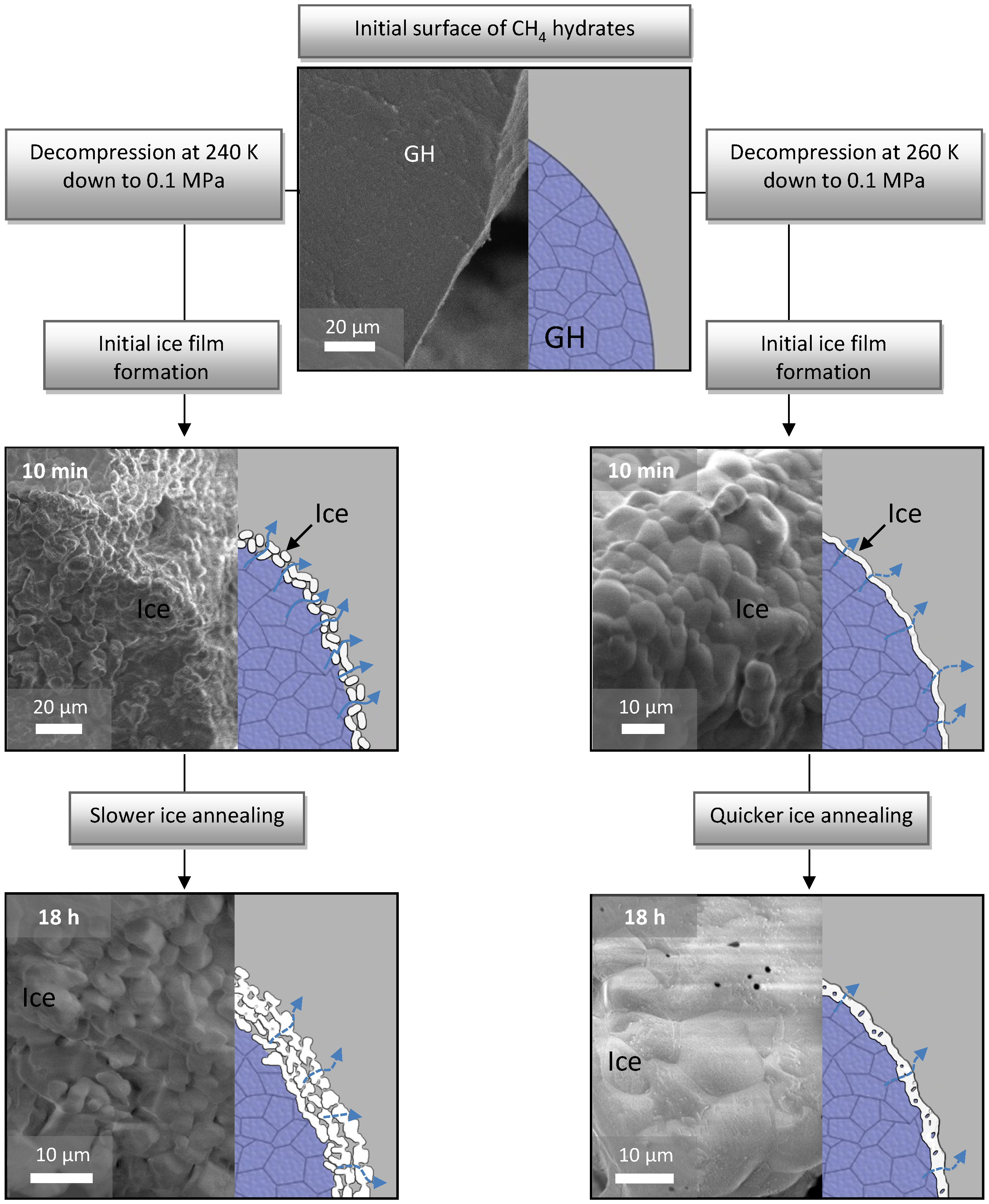
23]. A combination of all these parameters may ultimately lead to the so called “ice shielding” effect, in which even a fairly thin ice film (a few µm [
15]) creates an efficient diffusion barrier for unlocked gas molecules (
Figure 1).
Figure 1.
Formation of the self-preservation effect at 240 and 260 K through the stages of different initial ice microstructures and subsequent annealing. Reconstruction of the process shown on the right side of every picture is based on extensive cryo-FE-SEM imaging (left part of every image).
Figure 1.
Formation of the self-preservation effect at 240 and 260 K through the stages of different initial ice microstructures and subsequent annealing. Reconstruction of the process shown on the right side of every picture is based on extensive cryo-FE-SEM imaging (left part of every image).
Most likely the unlocked gas molecules are dissolved in the boundary layer between ice and clathrate, maintaining the necessary chemical activity for hydrate stability–thus the ice shield does not have to withstand high gas pressures [
21]. Following this argumentation self-preservation should be seen as a complex surface phenomenon, in which the part of clathrates exposed to the outside atmosphere is sacrificed to create a protective ice coating. Since the thickness of the ice layer is generally independent of the particle size, it is possible to improve the overall efficiency of self-preservation by changing the surface/volume ratio [
24] reflected in the controlling parameters particle size and porosity. Numerous studies have demonstrated that larger particles with a low residual porosity exhibit a far greater degree of preservation than fine grained material destabilised at the same p-T conditions [
15,
16,
19,
24]. Moreover, larger pieces of clathrates may also show the phenomenon at less suitable conditions yet at greater expense of original material. At favourable p-T conditions with well controlled particle size, only a minute portion of the original clathrate hydrate must be destroyed in order to create a continuous ice coating that could shield the unstable structure from a further rapid decay. In this meta-stable state clathrate hydrates may be capable of retaining a large volume of gas even for a few weeks at fairly mild conditions, far from the stability field [
19],
i.e., several degrees below the melting point of ice at ambient or slightly elevated pressure.
The general picture of self-preservation became gradually clearer over the last several years but it should also be emphasized that a full understanding is not achieved. The application of this phenomenon in a technological process still forms a considerable challenge and needs further substantial engineering efforts despite its well-established physical basis.
One of the highest concerns is raised by the fact that not all gas hydrates exhibit such a dissociation anomaly [
25,
26]. There are two commonly formed von Stackelberg structures (sI and sII) when hydrates crystallize; CH
4 and CO
2 hydrates belong to sI and both usually enter the self-preserved state. Some sII hydrates formed by e.g., mixtures of hydrocarbons show either large difficulty in reaching the preserved state or no anomaly at all. Likewise, some higher hydrocarbons as well as some (partially) fluorinated hydrocarbons show no or only limited self-preservation, both in sI and sII structures [
18]. This certainly is not fully understood and so far only treated in a phenomenological way without any satisfactory explanation [
25,
26]. On the positive side though, it should be noted that most of the prospective natural gas hydrates contained in a sedimentary matrix (that are thought to supply the NGH-based transport chain) consist of methane-rich sI hydrates largely free of higher hydrocarbons, gas compositions for which the existence of the phenomenon of self-preservation is rather likely. Compositions with higher hydrocarbons (structure sII former) of thermogenic origin are less common.
The other persistent unknown is the high variation of the dissociation rates within the self-preservation field. The particularly well established dissociation rates of CH
4 hydrates (sI) decompressed to ambient pressure [
11] show two strong minima (measured at 50% transformation) at ~250 and 267 K separated by a region of clearly weaker phenomenon. A similar or slightly less pronounced behaviour has been found also for other gas hydrates. Furthermore, recent experiments in a broader p-T field within the self-preservation region performed within this project put into question the generally assumed standard transport conditions at 0.1 MPa as the most suitable for maximum preservation [
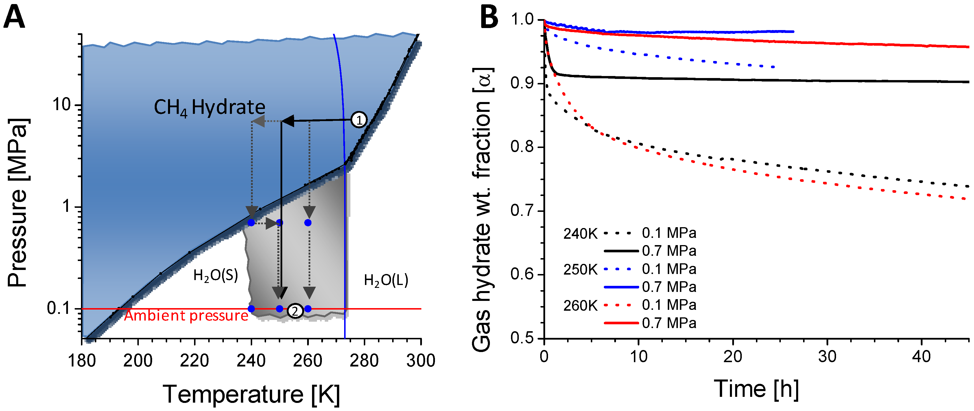
16] (
Figure 2). Although more extensive studies are still needed, the available experimental results suggest lower dissociation rates in a narrow field at elevated target pressures. For a technological application these observations are somewhat disturbing since it calls for a tight control of the formation process. If higher target pressures are to be considered to maximise the amount of transported gas, one needs to foresee pressurised containment vessels for the transport (see
Section 4). A tight control of pressure and temperatures seems mandatory during transport to control the dissociation rates of self-preserved hydrates as well as to mitigate the sintering of ice coatings around the gas hydrate pellets [
27]. Thus it is unlikely that a passive cooling, provided by the endothermic dissociation of gas hydrates, is sufficient; active cooling is likely to be needed.
Figure 2.
(A) Stability field of methane hydrates (in blue) drawn on the CH4-H2O phase diagram. Gray area marks the p-T region where the anomalous dissociation exists. Black arrows show a typical one step depressurization to a target pressure from planned production (1) to the transport conditions within the self-preservation region (2). Gray dotted arrows mark other potential depressurization pathways like multiple step decompression with/without a temperature change to facilitate particular initial microstructures/annealing rates during the ice coating formation; (B) Decompressive dissociation of consolidated cylindrical samples of CH4 hydrate with residual porosity of 40% at three selected p-T conditions (blue symbols in plot A).
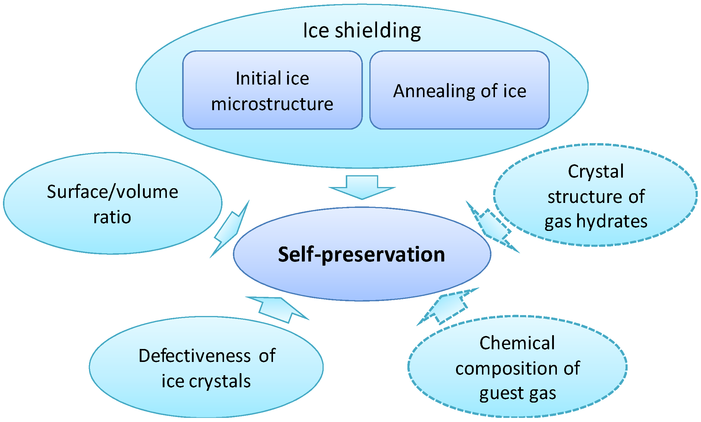
Figure 3.
Main components influencing the existence and strength of the self-preservation effect. The fields outlined with dashed lines mark elements that are recognized to be important for the anomaly, but for which the underlying mechanisms are still unclear.
Figure 3.
Main components influencing the existence and strength of the self-preservation effect. The fields outlined with dashed lines mark elements that are recognized to be important for the anomaly, but for which the underlying mechanisms are still unclear.
In summary, the effect of self-preservation is solidly established and has a sound, well understood physical basis (
Figure 3). Details of the process are, however, not sufficiently clear to define optimal conditions for an application at large scale. Undoubtedly, further R&D efforts would be needed to tailor the p-T path in the production and recovery process. The application of additives to promote the recrystallisation (and hence densification) of the formed ice layer appears to be a further possible line of research; to improve the ice shielding effect without any increase of the unwanted sintering would undoubtedly be a considerable challenge. Despite this obvious need for research, the bottleneck for an economic application appears to be not so much the mastering of the self-preservation process itself, but the cost of hydrate production as well as of the necessary infrastructure (see
Section 6).
3. Conceptual Design of a Methane Hydrate Pellet Production Process
On the basis of the laboratory and demonstration projects highlighted in the introductory chapter of this communication, a five step process sequence has been defined for methane hydrate pellet production, comprising: (i) hydrate formation; (ii) dewatering; (iii) pelletisation; (iv) pellet cooling; and (v) pressure relief. In the following sections, available technologies for each process step are discussed and a conceptual methane hydrate pellet production process is proposed.
Gas hydrates in laboratory applications are often prepared from the gas and ice phase, because of the better control on physical and chemical parameters (
i.e., porosity, transformation degree, structure type, composition) and easier handling. However, on an industrial scale, this formation path seems to be disadvantageous due to its low formation rate. This also applies to bubble columns, as for the required technical scales, liquid phase gas dispersion and thus the achievable interfacial areas are limited [
28]. From the literature, it can be concluded that continuously stirred tank reactors (CSTRs), static mixers and spray reactors show sufficiently good hydrate formation rates for the proposed process [
29,
30]. With regard to energy efficiency in general, the energy demand for the dispersion of the reactants is significantly lower than the cooling requirements for formation heat removal, which is mainly dependent on the hydrate structure, respectively, the guest gas. Considering the efficiency of heat removal from the reactor, a desired high level of process continuity, and a proven potential for scaling into technically relevant dimensions, CSTRs and static mixers appear favourable in comparison to spray reactors or spray chambers. As CSTRs are a standard component and widely used in the chemical and process industry, it was decided to assume this reactor type for hydrate formation, which is in accordance with the laboratory results published by the British Gas Group/Advantica [
6] and with the design of the demonstration projects by MES in Japan [
7].
Producing methane hydrate in a CSTR enables the formation of a gas hydrate slurry with approximately 90 wt% water content. Before the hydrate particles with typical diameters between 10 and 50 μm [
31] can be pelletized, the water content must be reduced to around 50 wt%. For a first approach, ice silos as applied by MES and, alternatively, reverse hydrocyclones have been considered appropriate for this task because in contrast to centrifuges they do not possess any fast rotating parts. Reverse hydrocyclones, however, allow for dewatering down to 70 wt% residual water content only. Furthermore, a certain degree of solid particle,
i.e., hydrate, loss cannot be avoided. The application of ice silos for large scale offshore applications seems challenging, as long residence times and consequently large volumes are required to reach the desired dewatering effect. By taking into account further criteria such as process continuity and energy efficiency, pressure drum filters have been chosen for the given task. These devices comprise a slowly rotating drum which is immersed in the hydrate slurry. The suspension is deposited on the filtering surface and, due to a pressure difference between the outside and the inside of the drum, liquid is forced into the inside. The dewatered filter cake is removed by a scraper before the surface is immersed in the slurry again. By appropriately choosing the process filter and adjusting the process pressures, particles with diameters smaller than 10 μm can be retained and residual water contents around 50 wt% can be achieved by this technology [
32].
The subsequent process of methane hydrate pelletisation allows for a reduction of storage volume and an optimisation of flow properties, most notably, material handling. Above all, as discussed in
Section 2 of this communication, the effect of self-preservation is more pronounced in pellets than in powder shape, with macroscopic size as well as porosity as influencing parameters. Physical properties of the pellets such as size, shape, strength, and porosity can be adjusted by the pelletiser design and choice of operating parameters. In the given application, it is desired to compact a hydrate slurry without binding agent and thermal treatment and, at the same time, to reduce the residual water content from approximately 50 to 10 wt%. In the demonstration plants of MES and partners, roller presses are used where the slurry is fed between two counterrotating cylinders and compacted in the gap [
9]. Alternatively, extruders can be applied where the substance is compacted by a matrix with normally circular openings (die plate). Depending on the extruder type, the required pressure is generated by screws, impellers or rollers. A special design is represented by horizontal matrix presses where a roller is working on a horizontal perforated plate. Additional grooves and openings can be integrated into the matrix to allow for simultaneous dehydration of the slurry. On the lower surface, the extrudate string is cut to the desired length. Inquiries with equipment manufacturers revealed that horizontal matrix presses allow for higher feed rates, lower equipment weight and lower space requirements than roller presses, so this pelletisation technology has been chosen for the conceptual process design. As pointed out by Takaoki
et al. [
33], a positive effect on storage efficiency can be achieved by producing multisized pellets, allowing the smaller pellets to fill gaps between bigger ones.
For cooling the pellets to the storage and transport temperature of −20 °C, direct contact with a cold methane gas flow has been assumed. The pellets are transported inside a housing in counter flow to the gas stream. Pellet transport can be achieved by gravity on an inclined surface or by conveying equipment such as screws, chains or belts. Due to the residual water content, it must be assumed that the pellets agglomerate during freezing unless relative motion is induced, e.g., by baffles or rotation of the housing. Finally, in order to store and transport the product in the anomalous self-preservation regime at atmospheric pressure, it is extracted from the high pressure section of the production plant. For this purpose, gas lock chambers operating in pairs have been chosen, i.e., twin locks which are alternately filled and discharged.
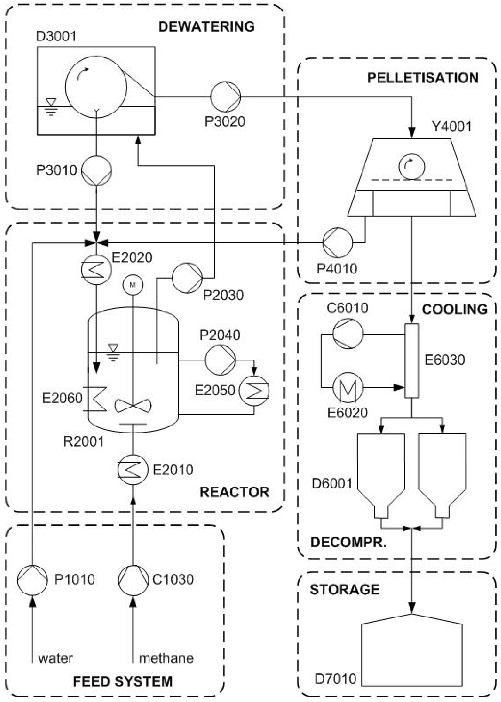
In
Figure 4, the flow diagram of the overall process concept is depicted. Besides the main equipment described above, it also contains the most important process pumps and heat exchangers. The educt streams of water and methane are compressed to 70 bar (P1010, C1030) and cooled to 7 °C (E2010, E2020) before they are fed to one or more CSTRs (R2001), depending on the assumed production capacity. For formation heat removal, a heat exchanger inside the reactor (E2060) and an additional cooling loop with slurry pump (P2040) and heat exchanger (E2050) outside the reactor are provided. The slurry with 10 wt% hydrate content is pumped to pressure drum filters (D3001) for dewatering to 50 wt% under stability conditions 70 bar and 7 °C. Subsequently, the thickened hydrate slurry is transferred to horizontal matrix presses (Y4001), where it is further dehumidified to 90 wt% hydrate content and pelletized under stability conditions. Excess water from the dewatering and pelletisation steps is fed back to the CSTR (P3010, P4010). Finally, the product is cooled (E6030), depressurized (D6001) and buffered (D7010) until it is transported onshore by a specialized methane hydrate pellet carrier (
Section 4 of this communication).
Figure 4.
Conceptual flow diagram for the methane hydrate production and pelletisation process.
Figure 4.
Conceptual flow diagram for the methane hydrate production and pelletisation process.
4. Conceptual Design of a Methane Hydrate Carrier Ship
The methane hydrate pellet carrier is one major link in a potential methane hydrate process chain, starting with the extraction of methane gas from the reservoir, followed by the production of hydrate pellets and the transportation to an onshore terminal for further processing or marketing. Constrained by the properties of the transported good (
i.e., methane hydrate,
Section 2 and
Section 3 of this communication), the expected operation on continental slopes in areas with rough seas, a scenario-defined loading capacity of 20,000 m
3 methane hydrate pellets, and safety as well as environmental considerations (
Section 5), a methane hydrate carrier including a cargo handling and storage system has been conceptually designed.
Due to the fact that natural gas transportation via methane hydrate pellets represents an innovative approach, no final codes for gas hydrate carriers are existent yet. Within the scope of this study, the International Gas Code (IGC) [
34] in general and the “Draft interim guidelines for the construction and equipment of ships carrying natural gas hydrate pellets (NGHP) in bulk” [
35] in particular have therefore been taken into consideration for the design of the hydrate carrier and its subsystems.
To assess the requirements from the potential areas of operation (e.g., the continental slope in the North Atlantic) and the necessity of all-year operation as far as reasonably possible, MEYER WERFT worked closely together with experts from the Technical University Berlin and specialists from the nautical side (captains, pilots,
etc.), taking into consideration the possible weather impact on both vessels (
i.e., production vessel and pellet carrier) during joined, non-independent operation. Furthermore, the independent Hamburg Ship Model Basin HSVA (Hamburgische Schiffbau-Versuchsanstalt) was subcontracted to carry out relevant model tests to obtain realistic figures of the sea-keeping characteristics of the vessels in bad weather. The results suggest that the use of a floating production, storage and offloading (FPSO) unit for production, buffering, and cargo transfer (solid material, no gas and no liquid) to the carrier in a rather short but controlled distance between 40 and 70 meters to the pellet production unit in the so called “tandem configuration” is the best option and possible under reasonable weather conditions. Furthermore, outstanding sea-keeping capabilities as well as positioning capabilities have to be guaranteed for the carrier ship. In order to match these requirements, efficient and powerful propulsion systems have been selected, together with a tailor-made dynamic positioning system and an optimized ship design. To match the requirement of utilizing the boil off gas from gas hydrate dissociation, a dual fuel engine concept was chosen. This measure also assists in meeting more stringent emission standards in the vicinity of shorelines and in harbours. The resulting main characteristics of the pellet carrier are summarized in
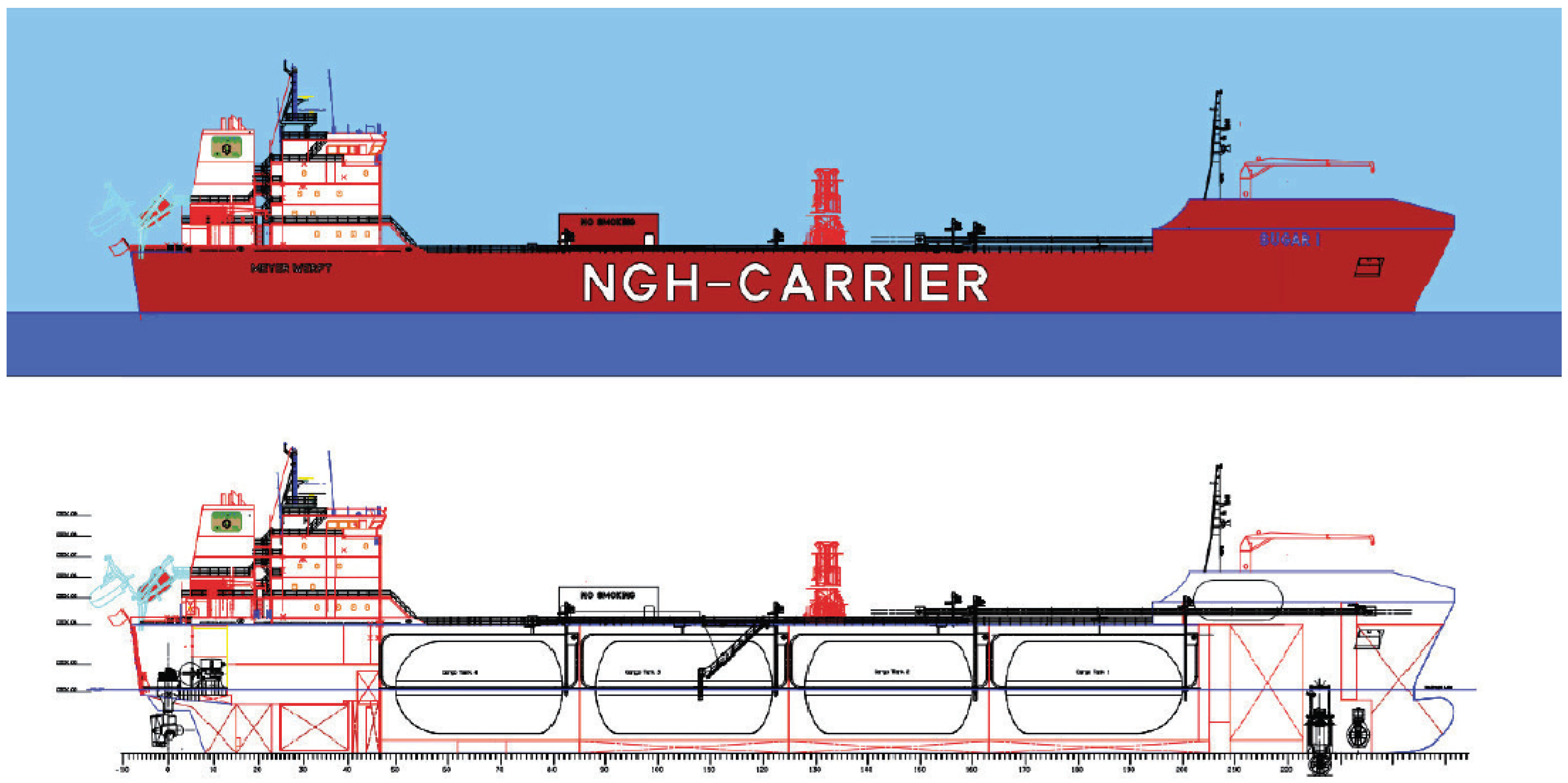
Table 1 and a conceptual design drawing is given in
Figure 5.
Table 1.
Pellet carrier main characteristics.
Table 1.
Pellet carrier main characteristics.
| length overall | m | 176.60 |
| length between perpendiculars | m | 166.00 |
| breadth | m | 30.60 |
| height | m | 16.90 |
| maximum draught | m | 8.40 |
| deadweight | t | 16,650 |
| tank volume at 100% | m3 | 20,000 |
| engine concept | - | dual fuel |
| dynamic positioning | - | DP2 |
| classification | - | Germanischer Lloyd |
Figure 5.
Design drawing of the pellet carrier.
Figure 5.
Design drawing of the pellet carrier.
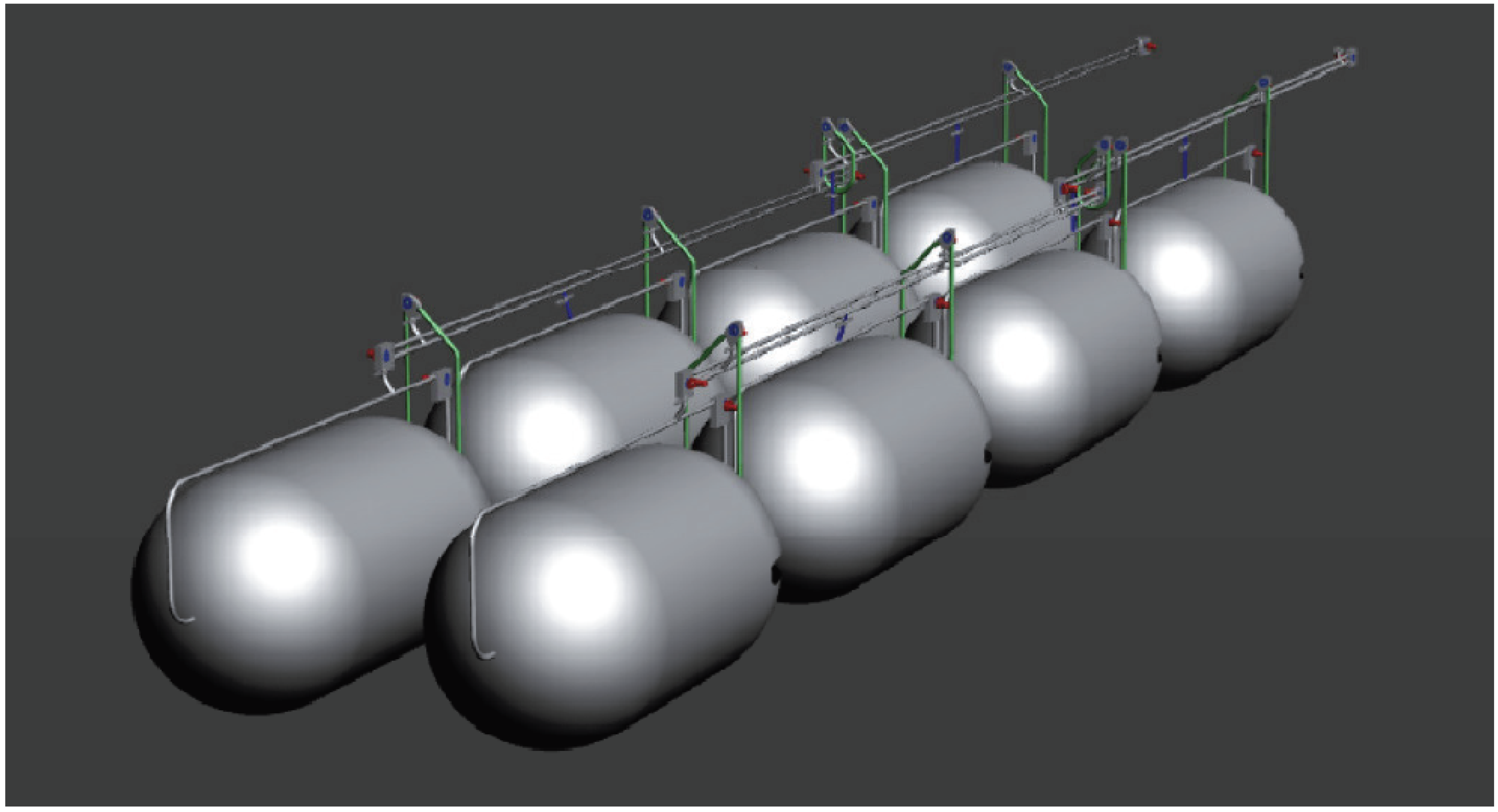
For the safe distribution and loading/offloading of methane hydrate pellets, a special cargo containment system with cargo handling facilities according to
Figure 6 has been designed. The containment system consists of eight cylindrical cargo tanks, arranged horizontally and pivot-mounted, each with an intake capacity of 2500 m
3. By tank rotation, sintering of the methane hydrate pellets during ship transport is avoided, as this effect would heavily complicate the unloading process. The tanks are distributed in four insulated and actively cooled cargo holds, respectively, compartments and connected to a specially designed cargo handling system that distributes the pellets in the containment system with a high degree of redundancy. The development and specification of the cargo handling system has been carried out in close cooperation with the conveying equipment manufacturer DD Dove, Wilhelmshaven/Germany. It basically consists of a chain conveyor system with a capacity of approximately 160 m
3 methane hydrate pellets per hour. The complete containment system, including the chain conveyor system, is designed for a temperature of −20 °C and a pressure of up to 2 bar. These conditions are vital to stabilize the pellet cargo in the self-preservation regime for efficient transportation, and have to be maintained during the loading process as well as during the transportation and discharge phases.
Figure 6.
Conceptual design of horizontally pivoted cylindrical tanks.
Figure 6.
Conceptual design of horizontally pivoted cylindrical tanks.
In comparison to the outlines for a NGH ship design published by MES so far [
36,
37], the cargo system is more complex, a consequence of constraints identified within the project (engineering and risk analysis), and partly additionally supported by new results from the literature on the physical properties of gas hydrates (
Section 2 and [
27]). The cargo handling concept is also following the results from the tests subcontracted to HSVA, which indicated that the behaviour of the vessels (FPSO and carrier) during bad weather with heavy seas does not permit a continuous cargo handling, which means that loading of the pellet carrier will have to be interrupted for certain periods. For the production unit, this resulted in the necessity for sufficient capacity to store the produced pellets while loading is not possible, one of the strengths of an FPSO. For the carrier, the requirement is to take the cargo at high rates in relatively short times to accommodate safe loading within limited time slots of good weather conditions. Active cooling and a confined, slightly over-pressurized containment system allow for optimized conditions to maintain and maximize self-preservation properties. Use of the boil off gas also plays an important role for safety considerations (
Section 5). The pivoted tanks are an additional element to reduce the risk of sintering, now identified as a major problem of the technology by a recent, detailed study on hydrates performed by Hokkaido University [
27].
5. Risk Analysis of Methane Hydrate Pellet Transport
Sea transport of natural gas in form of methane-hydrate is a new technological approach. Introducing new technologies bears always the possibility of introducing new risks or-in case of alternatives for already existing technical solutions-higher risks, either human, environmental, or property related. Today, in the maritime industry regulators-Flag states and International Maritime Organisation (IMO), a specialized agency of the United Nations-ask for a pro-active evaluation of new maritime technologies with respect to their impact on human safety and environment before their approval. Typically, such an evaluation is performed using risk analysis.
In order to identify so-called showstoppers for the methane hydrate transport technology at sea already in a design phase, which may hamper the introduction of the new technology or cause unnecessarily high costs for the improvement of the design, a risk analysis has been carried out in this early stage of development.
The risk analysis consists of the following steps:
Hazard Identification (HazId);
Ranking of the hazards;
Development of a risk model;
Evaluation of the risk (quantitative risk evaluation).
For the methane-hydrate carrier the HazId was based on two columns: brainstorming expert sessions and evaluation of risk analyses for ship types used for comparable purposes, i.e., Liquefied Natural Gas (LNG) carrier and Crude Oil Tanker.
In the expert sessions for hazard identification the Failure Modes, Effects and Criticality Analysis (FMECA) was applied [
38]. For the purpose of ranking the identified hazards, the probability of occurrence and the severity of the consequences were estimated using index tables. These tables for frequency index (FI) and severity index (SI) are based on logarithmic-scaled graduation for incident frequency and consequences. The ranking was performed on basis of the risk index (RI) which is the summation of FI and SI. This approach is in full agreement with the proposals made in the Formal Safety Assessment (FSA) guidelines [
39] of IMO. However, this approach deviates from the approach used in other industries, e.g., automobile industry, which is based on non-logarithmic based index tables and a multiplication of both indices, the so-called risk priority number (RPN). But, as shown by Braband [
40], the risk index avoids several “flaws” of the RPN concept.
In general, the FSA guidelines consider the environmental aspect only rudimentarily and contain no SI model for methane releases. Therefore, such a model was developed within the project based on an analysis of natural methane emissions (
Table 2).
Table 2.
Severity Index table for CH4 release.
Table 2.
Severity Index table for CH4 release.
| SI | Severity | CH4 released | Remarks |
|---|
| 1 | negligible | 10 t | This amount of CH4 is equivalent to the natural release of 100 cattle per year |
| 2 | significant | 100 t | Capacity of a tank of current design |
| 3 | severe | 1000 t | About 50% of total capacity of current design concept |
| 4 | catastrophic | 10,000 t | CH4 emissions in Germany in 2009 by traffic were 7000 t |
| 5 | disastrous | 100,000 t | CH4 emissions in Germany in 2009 in the field of energy production were 76,000 t |
For the SUGAR project, three FMECA sessions focusing on sea journey, loading and un-loading were performed, accompanying the development of the pellet carrier. Experts covering the fields of naval architecture, basic methane hydrate properties, ship machinery, gas tanker design, and use of gas as ship fuel were recruited for these sessions.
The highest RIs related to human safety were obtained for collision, contact, fire and failures of safety equipment (safety valves). With respect to the environment, highest RIs were identified for failures of safety equipment (safety valves), collision, too high boil-off, and structural failure of the hull or tank.
Based on this HazId and an additional examination of risk analyses on LNG Tankers and Crude Oil Tankers in recent years submitted to IMO (LNG tankers: MSC 83/INF.3, [
41]; Crude Oil Tankers: MEPC 58/INF.2, [
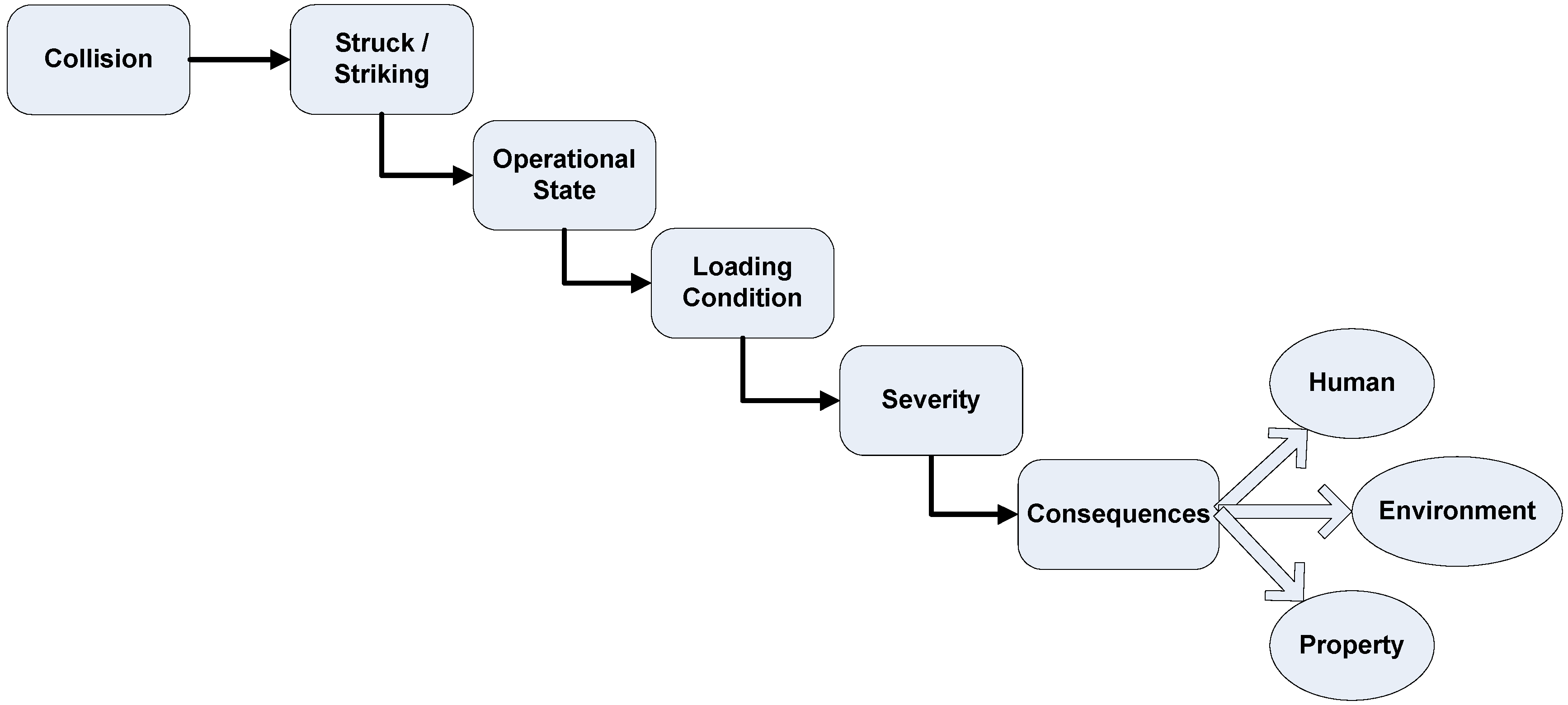
42], a risk model was developed considering the accident categories collision, grounding and accidental release of methane due to equipment failure (e.g., piping, valves and tanks). For these accident categories so-called high level event sequences were developed that form the basis of the event trees. Exemplarily, the high level event sequence for collision is shown in
Figure 7. The quantitative risk model for the three accident categories mentioned was developed in form of such event trees [
43].
Figure 7.
High level accident sequence for accident category collision.
Figure 7.
High level accident sequence for accident category collision.
In a quantitative risk model, absolute and dependent probabilities are used to calculate the probability of all scenarios initiated by the accident under consideration. The methane pellet carrier is a new transport concept and hence data required to determine the input data for the risk model is not available. Typically, expert judgement is used to overcome this problem. For the present study the data provided by the FSAs (LNG carriers and Crude Oil Tankers) was used and, as far as possible, updated by latest available data for these ship types.
For instance, the initial accident frequency was determined based on the fleet on risk (ships active) and the accidents for the period 1995 to 2010. Fleet on risk was determined using the IHS-Fairplay database and casualties with the help of IHS-Fairplay and the accidents listed in the FSAs. Based on these sources, the initial accident frequency for collision was determined to 1.6 × 10⁻³ per ship year and for grounding to 5.2 × 10⁻⁴ per ship year. However, caused by the relatively small sample (LNG-fleet) and the small number of accidents, the uncertainty for the initial accident frequency is relatively high, so for collision the 95% percentile (i.e., the 95% probability that the accident frequency is lower than this value) is 4.6·× 10−3 and for grounding 2.9·× 10−3.
The dependent probabilities for hull penetration (in case of collision or grounding) as well as for penetration of the cargo tanks were estimated using the respective part of the oil outflow model of MARPOL [
44], which allows the calculation of the probability for penetration location and depth.
Consequences are focused on human and environmental safety, i.e., fatalities and environmental pollution, which in this case is the release of the greenhouse gas methane. Based on the information on the behaviour of methane hydrate it was assumed that methane hydrate will not be released abruptly when the containment is damaged in collision or grounding accidents, even if water ingress occurs, because the gas is not or only very moderately pressurised, bound in a crystalline network of cages made out of water molecules, and the decomposition is highly endothermic. The ignition of a fire is possible but it was expected that such a fire will be limited to the cargo space. Therefore, fatalities are related to sinking of the ship in case of collision and grounding. The number of crew is assumed with 25 and the fatality rate is set to 50% for the case that the ship sinks. Consequences for the environment occur in case of cargo tank damage or water ingress into the tank section because the water contact would cause a dissociation of the hydrate and a methane release via the safety valves. The amount of gas released in such an accident depends on the tank capacity (between 119 and 223 tonnes) and the number of tanks in one watertight section. For the event of methane releases that are not caused by collision or grounding but by leakages of flanges, piping system or cargo tanks, or by failures of the safety valves, frequencies were estimated by the experts during the FMECA sessions. The estimated amount of methane released is related to the capacity of the affected pipe section or tank and the possibility to detect the leakage and to separate the section under consideration.
The risk model is applied to calculate the characteristic risk values for human safety, expressed in terms of Potential Loss of Life (PLL), and for environmental safety, expressed in terms of Potential Loss of Cargo (PLC). In
Table 3, the characteristic risk values for the methane hydrate carrier calculated with the developed risk model for the accident categories collision and grounding are summarised.
The comparison with crude oil tanker and LNG vessel for the accident category collision showed that the risk for crew is lower than for both reference ship types. Among other effects, this is caused by the assumption that methane hydrate release will not cause fire. The environmental risk is also lower than for LNG vessels, however, this is an effect of the cargo capacity of the new transport concept which is about 30 times smaller than for an average LNG vessel.
Table 3.
Summary of characteristic risks for one design variant and for human and environmental risk.
Table 3.
Summary of characteristic risks for one design variant and for human and environmental risk.
| Accident category | PLL | PLC |
|---|
| | 1/ship year | t/ship year |
| Collision | 2.1 × 10⁻⁴ | 1.7·× 10−1 |
| Grounding | 1.0 × 10⁻⁴ | 2.6·× 10−2 |
In case of grounding, the risk for crew on a methane hydrate carrier is similar to that for crew on crude oil tankers and significantly lower than for crew on LNG vessels. However, for crude oil tanker crew the probability of being killed when grounding takes place is lower because the percentage of crew affected is significantly lower. For crude oil tankers, historical data was used to determine the percentage of affected crew. Such data is not available for the new technology, and so 50% of the crew is conservatively estimated as fatalities in case the ship is sinking. The difference to the LNG risk model is the result of higher initial accident frequency and the consideration of fire after grounding of an LNG carrier.
6. Energetic and Economic Analysis of Methane Hydrate Pellet Transport
For a comparative assessment of natural gas, respectively, methane transport options, a conceptual methane hydrate infrastructure has been compared with the established technologies of pipeline and LNG transportation. Furthermore, a comparison with CNG transport, another alternative that has been developed to an advanced conceptual stage at several places [
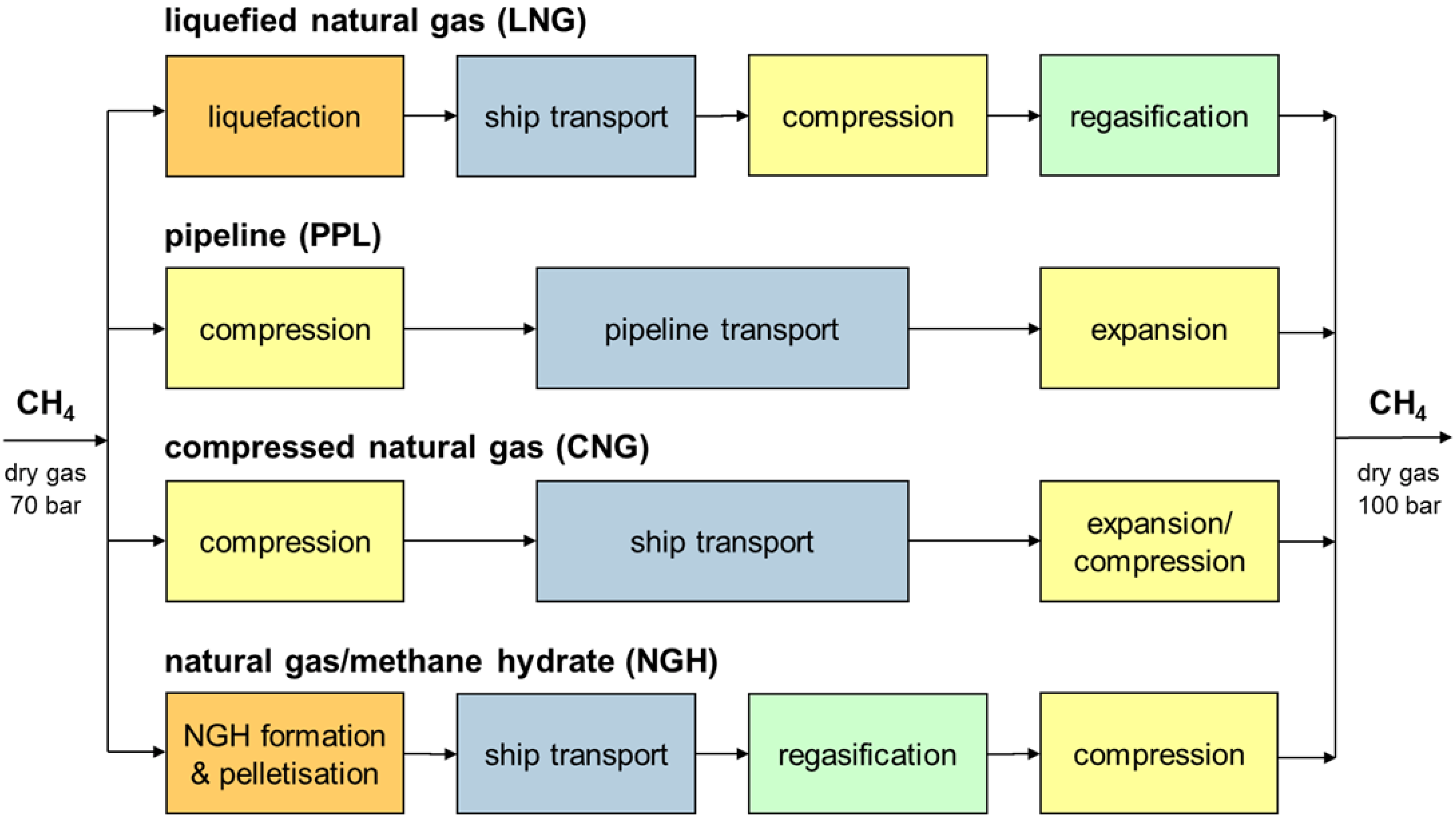
45] but not implemented on a large scale so far, has been conducted. As criteria, the overall energy consumption and total cost per weight unit of gas transported to an onshore terminal have been chosen. For the calculations, a conditioned and dry gas flow with 70 bar pressure has been assumed on the feed side. After processing and transfer, the gas shall be fed into an onshore natural gas transport pipeline with 100 bar operating pressure. With reference to
Figure 8, the following process chains have been defined to represent the individual technologies:
- (i)
LNG transport
Methane is liquefied on an offshore unit, buffered and loaded onto an LNG carrier. Transport is taking place at close to atmospheric pressure and −161 °C. Boil-off gas is used in the ship propulsion system and fired together with marine diesel fuel (heavy fuel oil, HFO). At the import terminal, the LNG is unloaded and buffered. After extraction from the tanks, the pressure is increased by cryogenic pumps, the liquid regasified by heat exchange with sea water, and the gas fed into the pipeline network.
- (ii)
Pipeline transport
Methane is compressed to 150 bar and directly fed into a subsea pipeline, i.e., no buffering on an offshore unit is assumed. For compensation of pressure drops along the pipeline, intermediate compressor stations on the sea floor must be installed. Onshore, the gas is expanded to the pipeline network pressure.
- (iii)
CNG transport
For CNG transport, the gas is compressed first and buffered on the offshore production unit. For ship transport, the Coselle
TM technology has been assumed where gas is stored under 220 bar pressure in spirally wound pipes inside the cargo hold of the carrier [
46]. At the import terminal, gas is either expanded or pressurized to pipeline conditions, depending on the level of Coselle
TM filling.
- (iv)
Methane hydrate transport
Methane hydrate pellets are produced according to the process described in chapter 3 and transported by a specialized carrier ship according to chapter 4 of this communication. In analogy to LNG transportation, boil-off gas from hydrate dissociation is used in the ship propulsion system and fired together with HFO. Based on literature data [
19], it is assumed that the dissociation rate is 0.2 wt% of the stored gas, which equals the typical boil-off rate of storage vessels on LNG carriers. At the import terminal, the pellets are unloaded, hydrate is dissociated by heat exchange with sea water, methane gas is compressed and fed into the pipeline network. Drying of the gas before feed-in has been neglected because in return the methane does not have to be fed into the hydrate formation reactor in a dry state.
Figure 8.
Technologies and system boundaries for a comparative assessment of natural gas transport options.
Figure 8.
Technologies and system boundaries for a comparative assessment of natural gas transport options.
With respect to LNG transport, a profound energetic and economic analysis could be carried out by taking into account both published data as well as engineering knowhow provided by the Linde Group Engineering Division for data verification and calibration. Also for pipeline transport, reliable data could be extracted from the literature and verified by expert judgement (ILF Consulting Engineers, Munich/Germany). Regarding CNG, respectively, CoselleTM transport, practical experience is lacking, thus the analyses had to be based on publications and studies alone that were brought together by an extensive literature review. Characteristic data for the methane hydrate production process and the hydrate carrier have been developed within the scope of the SUGAR joint project in close cooperation with key equipment manufacturers and specialist departments of Meyer Werft (Papenburg/Germany) and the Linde Group Engineering Division (Pullach/Germany).
For the individual process steps in
Figure 8, mass and energy balances as well as capital (CAPEX) and operating expenditures (OPEX) have been evaluated. The components have then been connected together to make up process chains, and scenarios have been defined to simulate realistic applications. In
Table 4, the major assumptions and model parameters are summarized.
Table 4.
Scenarios and model parameters for the comparative assessment of transport options.
Table 4.
Scenarios and model parameters for the comparative assessment of transport options.
scenarios:
production capacities | 103 Nm3·h−1 | 20/50/100/500/800 |
| transportation distances | km | 200/500/1000/2000/5000/10,000 |
| physical and technical parameters: |
| lower heating value of CH4 | kWh·kg−1 | 13.9 |
| lower heating value of HFO | kWh·kg−1 | 11.9 |
| density of CH4 | kg·Nm−3 | 0.72 |
| density of CH4 hydrate | kg·m−3 | 929 |
| Δh of CH4 hydrate | kWh·kggas−1 | 0.95 |
| ship speed | kn (km·h−1) | 19 (35) |
| ship propulsion efficiency | - | 0.30 |
| boiloff rates (LNG, hydrate) | d−1 | 0.0020 |
| pellet storage efficiency | - | 0.78 (multisize pellets) |
| economic parameters: | | |
| exchange rate (Φ2010) | U.S.$·€−1 | 1.33 |
| NG price (wellhead, Φ2010) | €·kg−1 | 0.153 |
| NG price (terminal, Φ2010) | €·kg−1 | 0.182 |
| HFO price (Φ2010) | €·kg−1 | 0.378 |
| production days per year | - | 333 |
| depreciation time | a | 20 |
| interest rate | - | 0.07 |
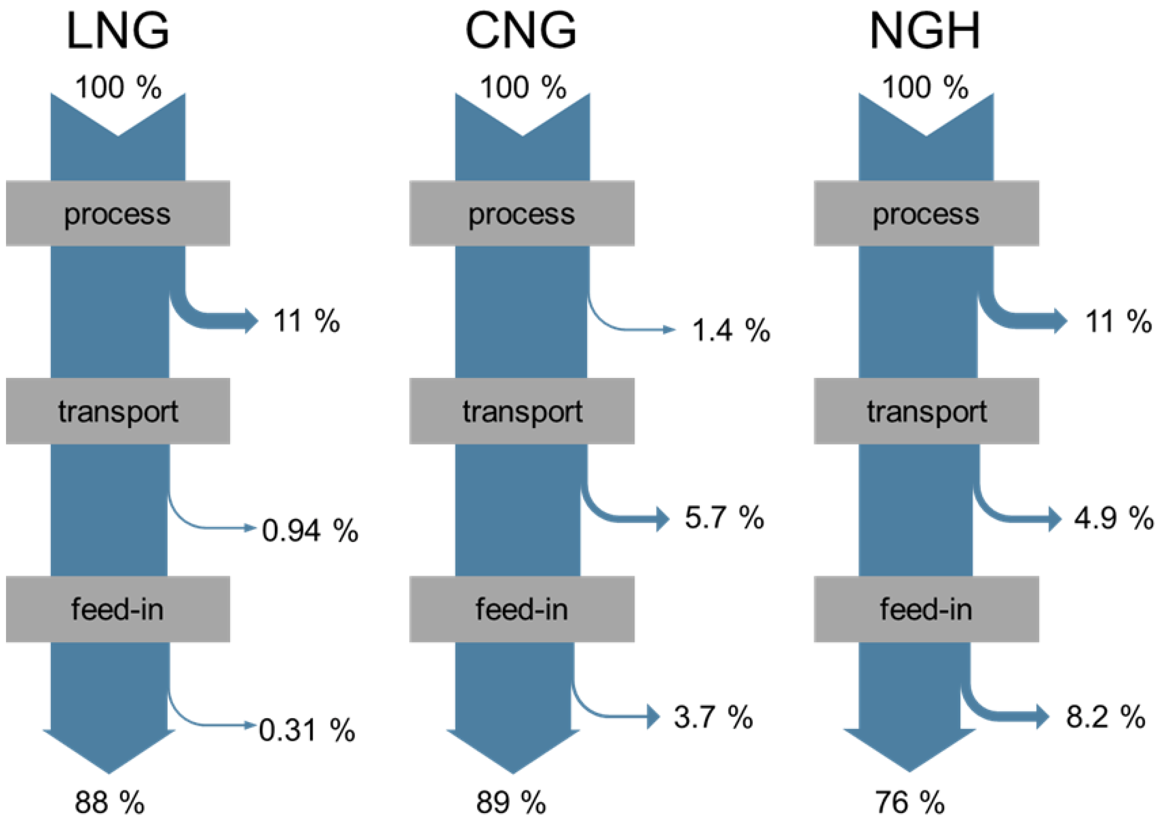
In
Figure 9, the energy flow diagrams (Sankey diagrams) for the technologies LNG, CNG and methane hydrate for the production scenario 20,000 Nm
3·h
−1 and a transportation distance of 1000 km are depicted. Under the given assumptions, the CNG process comprises only the compression of methane from 70 to 220 bar, which requires a comparatively low amount of energy. In the LNG case, 11% of the energy input are required to run the refrigeration process for methane liquefaction. Regarding methane hydrate pellet production, the process is estimated to be as energy intensive as methane liquefaction, with major contributions originating from formation heat removal (
ca. 41%), pelletisation (
ca. 35%) and pellet cooling (
ca. 15%). With respect to the transportation stage, the transfer of LNG is particularly energy efficient due to its high volumetric and gravimetric energy densities of 5.84 kWh·L
−1 and 13.9 kWh·kg
−1, respectively. In contrast, methane makes up for only 10 and 12 wt% of the cargo in the CNG and methane hydrate routes. The remaining weight is attributed to the transport vessels (Coselles
TM), respectively, the water molecules of the hydrate cages. Consequently, in order to transport the same amount of energy, both the CNG and methane hydrate routes are associated with an order of magnitude higher number of journeys between the offshore production site and the onshore terminal. Focussing on the feed-in into the onshore pipeline network, LNG technology is again the most efficient option because the product pressure can be increased in the liquid phase. For CNG, a redensification is required as soon as the gas pressure inside the storage vessel drops below the pipeline pressure. Methane originating from the dissociation of methane hydrate at the onshore terminal must always be compressed from atmospheric or close to atmospheric to pipeline pressure in the gas phase, thus possessing the highest energy demand for the feed-in process. Overall, as can be seen in
Figure 9 for the 20,000 Nm
3·h
−1/1000 km scenario, 12% of the energy input are dissipated along the LNG chain, 11% along the CNG chain and 24% along the methane hydrate chain. Not shown in
Figure 9 is pipeline transport, which would consume less than 1% of the energy input for the given scenario. In this case, merely an initial compression from 70 to 150 bar and the subsequent compensation of the pressure drop along the subsea pipeline are required.
Figure 9.
Energy flow diagrams for the transport options LNG, CNG and methane hydrate (20,000 Nm3·h−1/1000 km scenario).
Figure 9.
Energy flow diagrams for the transport options LNG, CNG and methane hydrate (20,000 Nm3·h−1/1000 km scenario).
In summary, with respect to energy efficiency under the given boundary conditions, it can be concluded that methane hydrate pellet transport has no potential benefit versus competing technologies. The most efficient solution is always pipeline transport; however, this option is subject to economic constraints with increasing transportation distance, as will be shown below. Apart from that, CNG transport is more energy efficient for small and LNG transport for medium to large distances, in particular for increasing capacities.
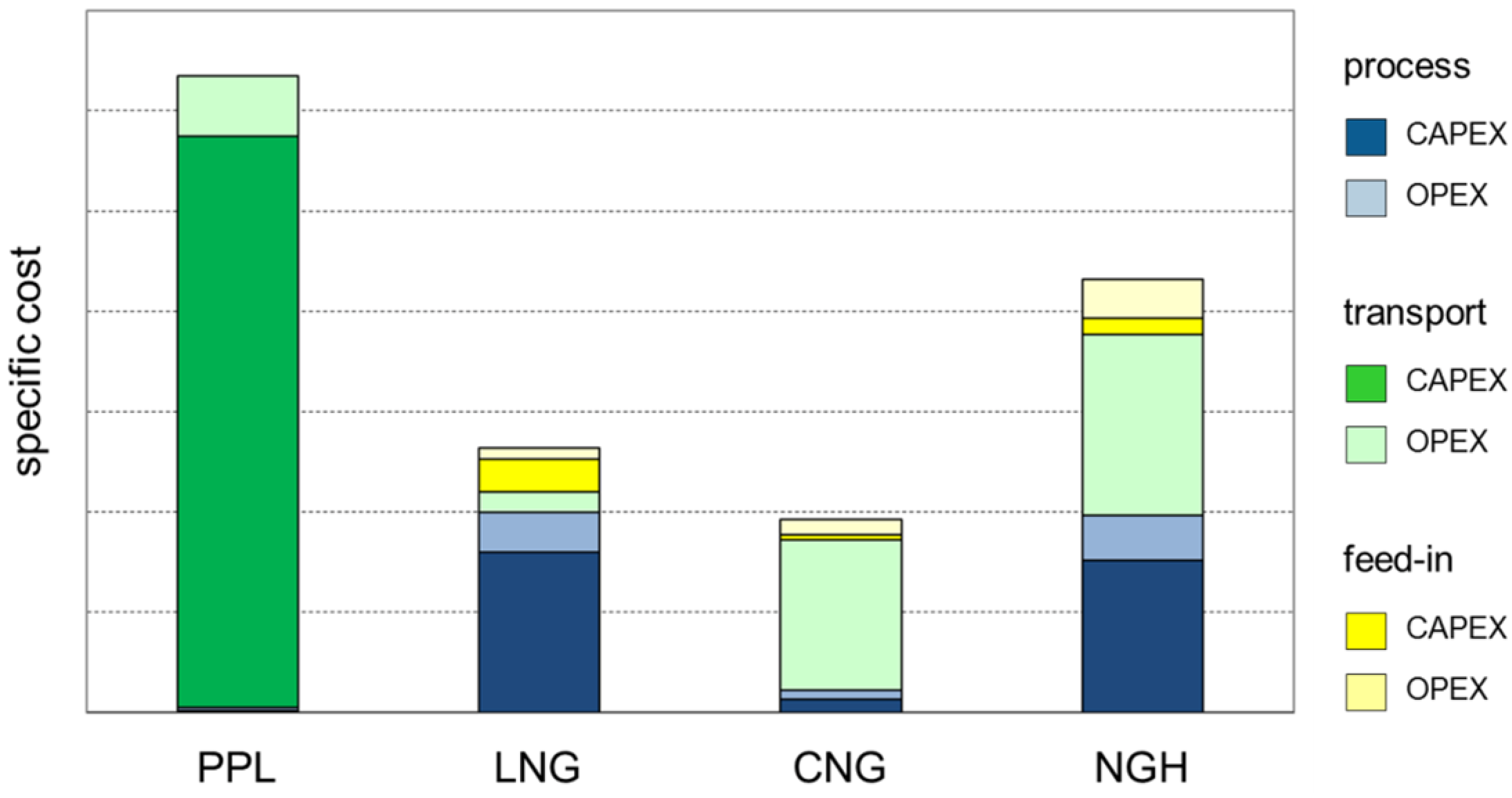
For a demonstration of the economic relations, the total specific costs of methane transport technologies are depicted in
Figure 10, considering again the 20,000 Nm
3·h
−1/1000 km scenario. Specific costs have been calculated by dividing the total costs,
i.e., CAPEX plus OPEX, by the mass of methane gas fed into the onshore pipeline network for each individual transportation route. The economic datasets comprise the construction and operation of the gas processes preceding transport (compression, liquefaction, methane hydrate pellet production) and of the feed-in processes after transport. For the pipeline route, the construction and operation of the subsea pipeline has been included into the evaluation. In contrast, the LNG, CNG and methane hydrate routes possess only an OPEX component because a chartered carrier fleet has been assumed. Charter fees have been assembled from various sources,
i.e., [
47,
48,
49,
50], and a single linear relationship with the cargo weight has been implemented for all carrier types in this study. Due to the high volatility of charter rates, which are massively dependent on supply and demand fluctuations on the global market [
51], a differentiated allocation to the individual transport options has not been possible at this point. In all analyses, the costs for the offshore units hosting the production, respectively, process plants such as platforms and floaters, as well as the costs of loading/unloading systems have been neglected. It can be assumed that this simplification has a particularly positive effect on the economy of the methane hydrate route, as the production, storage and handling of a solid material is a challenging task under rough sea conditions that has to be addressed by special technical measures.
As can be seen from
Figure 10, the total costs of pipeline technology are dominated by the construction of the subsea infrastructure, whereas contributions from the gas process and feed-in can be neglected. Thus, from an economic point of view, pipeline transport is especially relevant for medium to large capacities and small to medium distances. With regard to LNG technology, the CAPEX for the liquefaction plant is significant, whereas the OPEX for ship transport is comparatively low. Consequently, the LNG option is generally applied for medium to large capacities and distances. For CNG technology, the conclusions are vice versa as the process plant is comparatively simple and total specific cost is dominated by charter fees and HFO cost (
i.e., transport CAPEX). This can be attributed to the poor energy density of the storage system. Consequently, CNG may find its niche for applications with small capacities and small to medium distances to the market. With respect to gas hydrate technology, both the capital-intensive production plant as well as the low energy density of the pellets, resulting in high transportation OPEX, have a disadvantageous effect on the overall economy.
Figure 10.
Specific total costs of the transport options pipeline (PPL), LNG, CNG and methane/natural gas hydrate (NGH) (20,000 Nm3·h−1/1000 km scenario).
Figure 10.
Specific total costs of the transport options pipeline (PPL), LNG, CNG and methane/natural gas hydrate (NGH) (20,000 Nm3·h−1/1000 km scenario).
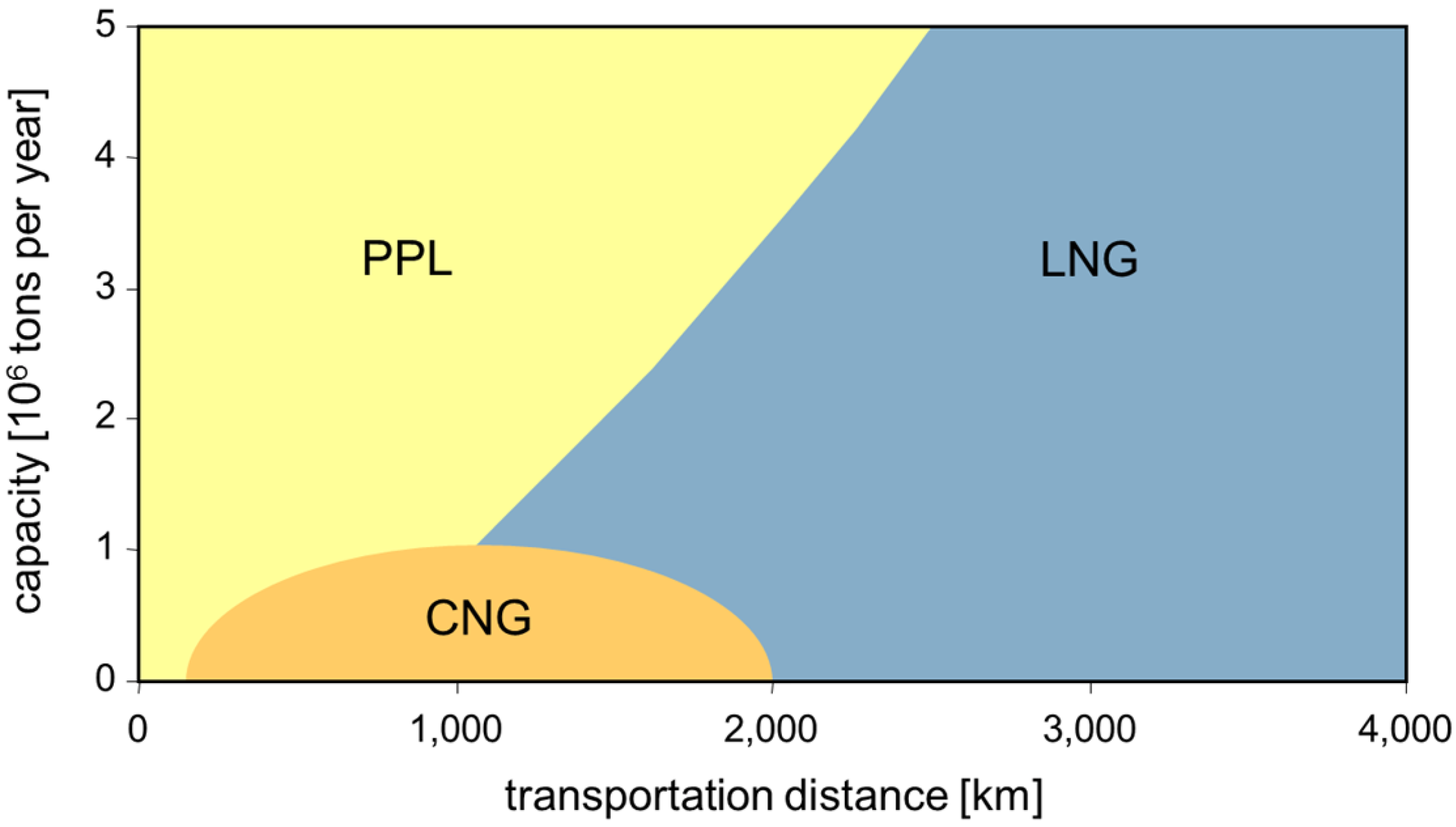
By calculating the total specific cost curves as a function of transportation distance for each technology and subsequent analysis of line intercepts at constant production rates, the map depicted in
Figure 11 has been generated. For the given boundary conditions, it indicates the most economic transport options for capacities between 0 and 5 megatons per year (MTPA),
i.e., up to approximately 800,000 Nm
3·h
−1, and transportation distances between 0 and 4000 km. In contrast to previous studies, the model calculations in this study reveal no economic benefit of methane hydrate transportation
versus competing technologies. For capacities above 1 MTPA, pipeline and LNG transport are the technologies of choice. An alternative for smaller capacities and distances up to 2000 km might be CNG transport.
Figure 11.
Economic comparison of natural gas transportation technologies in a capacity-distance-matrix.
Figure 11.
Economic comparison of natural gas transportation technologies in a capacity-distance-matrix.
Comparing these findings in more detail with early analyses carried out by NTNU Trondheim and Aker Technology [
52], it is worth noting that the specific costs for the LNG route do not differ significantly for comparable scenarios,
i.e., capacities and transportation distances. For the gas hydrate route, however, the economic figures in the Norwegian study are about half the figures in this study. Apparently, the Norwegian calculations are focused on capital cost, which may evoke a tolerable degree of uncertainty with respect to the CAPEX dominated LNG technology. For the gas hydrate scenarios with comparatively high OPEX contributions, however, this procedure appears insufficient. Analogue conclusions apply to more actual announcements by MES [
10], as these also rely on a comparative assessment of capital expenditures alone. In a recent paper published by Osokogwu
et al. from the University of Port Harcourt [
53], gas to liquid (GTL), gas to power (GTP), CNG and natural gas hydrate transportation technologies have been compared in a CAPEX and OPEX analysis under Nigerian boundary conditions. The authors concluded that with respect to profit, internal rate of return and payback period, CNG is the most advantageous option for an assumed natural gas production rate of approximately 0.3 MTPA, thus reinforcing the results presented in this communication.
7. Conclusions
The physics of the self-preservation effect, as key process for the transport of gas as hydrate pellets, has by now been mostly unrevealed. The underlying ice shielding effect is a complex consequence of ice formation at the hydrate boundary, and subsequent annealing. As both effects are governed by temperature and pressure, a control on both parameters during production and storage is advantageous. Further research is needed for technical application, in particular with respect to the effect of the gas composition on self-preservation, and the tailoring of the p-T path in the production and recovery process for optimizing dissociation rates and mechanical properties of the hydrate pellets, i.e., sintering.
On the basis of fundamental knowledge about methane hydrate formation and the anomalous self-preservation effect, a conceptual process design for methane hydrate production and pelletisation has been developed. As far as possible, proven and well-known technologies have been used as a toolbox for the individual process tasks, however, the given application required several modifications and assumptions. The main part of the process has an operating pressure of 70 bar, so for most of the components high wall thicknesses or pressure-resistant housings will be required in a technical realization. Furthermore, it can be expected that the sealing of moving parts and pellet handling under a high pressure methane atmosphere are challenging tasks. The functionality and long-term operability of key process equipment such as CSTRs, rotary drum type filters and horizontal matrix presses in a harsh marine environment must be proven and appropriate specifications be developed. Despite these uncertainties, the process concept represents a sound engineering solution and could be characterized by fundamental energetic and economic data in close cooperation with equipment manufacturers.
The design of a gas hydrate carrier, considering the current understanding of the properties of the cargo and foreseen mode of operation during loading and unloading, calls for a variety of new technological approaches. In particular, the needs for active cooling, as well as potential measures to mitigate sintering and minimize mechanical stress on the hydrate pellets in the self-preservation state, were challenges for the concept of the containment system. However, the design of the carrier presented in this communication, partly developed in cooperation with equipment manufacturers, represents a sound ship technological solution. The risk assessment for the transport of gas hydrate pellets at sea did not reveal any showstoppers for the technology. In fact, the assumed reduced risk of fire in comparison to LNG or crude oil transport offers potential benefits.
For a comparative assessment of the natural gas transportation options from an offshore reservoir to an onshore terminal, process chains for the pipeline, LNG, CNG and methane hydrate routes have been synthesized and appropriate application scenarios have been defined. As criteria, energy efficiency and total specific cost, i.e., capital and operating expenditures per weight unit of gas fed into an onshore pipeline network, have been applied. Model calculations led to the conclusion that the proposed methane hydrate infrastructure shows neither an energetic nor an economic benefit versus the established technologies pipeline and LNG transport, respectively, CNG transport as innovative approach for smaller capacities and small to medium distances. This result is attributed to the expected high investment cost of the methane hydrate production and pelletisation process and the high charter and fuel costs associated with the ship transport of low energy density methane hydrate pellets.
In summary, several advantages of gas hydrate technology do exist, such as an inherent safety against ignition and uncontrolled burning or the robustness of the methane hydrate production process against water, heavy hydrocarbons and carbon dioxide. However, the work presented in this communication has revealed major disadvantages of methane hydrate transport with regard to energy efficiency and economy. Furthermore, the handling and transfer of a solid bulk material under rough offshore conditions appears rather challenging in comparison to the handling and transfer of a liquid or a gaseous phase. On the basis of our analysis, a scenario for which the gas hydrate transport technology could compete with well established or emerging technologies for gas transport from offshore sources to land could not be identified.


