Article

Retrofitting Domestic Hot Water Heaters for Solar Water Heating Systems in Single-Family Houses in a Cold Climate: A Theoretical Analysis

1
Energy and Building Design Division, Lund University, Box 118 SE-221 00 Lund, Sweden
2
Division of Energy, School of Sustainable Development of Society and Technology, Högskoleplan 2, Gåsmyrevreten, SE-721 23 Västerås, Sweden
*
Author to whom correspondence should be addressed.
Energies 2012, 5(10), 4110-4131; https://doi.org/10.3390/en5104110
Submission received: 20 July 2012 / Revised: 15 October 2012 / Accepted: 15 October 2012 / Published: 22 October 2012

Abstract

:
One of the biggest obstacles to economic profitability of solar water heating systems is the investment cost. Retrofitting existing domestic hot water heaters when a new solar hot water system is installed can reduce both the installation and material costs. In this study, retrofitting existing water heaters for solar water heating systems in Swedish single-family houses was theoretically investigated using the TRNSYS software. Four simulation models using forced circulation flow with different system configurations and control strategies were simulated and analysed in the study. A comparison with a standard solar thermal system was also presented based on the annual solar fraction. The simulation results indicate that the retrofitting configuration achieving the highest annual performance consists of a system where the existing tank is used as storage for the solar heat and a smaller tank with a heater is added in series to make sure that the required outlet temperature can be met. An external heat exchanger is used between the collector circuit and the existing tank. For this retrofitted system an annual solar fraction of 50.5% was achieved. A conventional solar thermal system using a standard solar tank achieves a comparable performance for the same total storage volume, collector area and reference conditions.

Graphical Abstract

1. Introduction

One of the biggest obstacles to the economic profitability of domestic solar water heating (SWH) systems is the investment cost [1,2,3]. The installation cost of forced circulation systems used in cold climates can represent up to 50% of the total investment cost depending on the size and type of system [4]. Also, the solar storage is one of the most expensive components in a solar water heating system [1]. Retrofitting existing domestic water heaters when new SWH systems are installed can reduce the total investment cost by decreasing both the installation and material costs. In Sweden there are more than half a million electrically heated single family houses that use conventional water heaters for domestic hot water production [5]. Such retrofitting needs to be carried out with consideration of the cold Swedish climate. In such regions the solar storage is placed indoors and a freeze protection medium runs inside the collector circuit. Since existing water heaters are not provided with a heat exchanger, an external one should be used. There are two main types of systems designed with an external heat exchanger outside the storage: thermosyphon and forced flow circulation.
Cruickshank and Harrison, in 2004 [6] and 2006 [7], investigated this type of thermosyphon systems in the Canadian cold climate. In 2011 [8], the same authors studied the performance of series and parallel connected thermosyphon storages. Thermosyphon systems became popular in several parts of the world such as Eastern Asia and Australia, mainly due to their simplicity and reliability [9]. The thermosyphon driving force depends on the pressure difference and frictional losses between the heat exchanger side-arm and the tank. Hence, the generated flow will be a complex function of the state of charge of the tank, the temperature profile along the heat exchanger and pipes, the height difference between the top of the heat exchanger and the top of the tank and the pressure drop in the heat exchanger, piping and connections [7,10,11]. Such dependence on the heat exchanger pressure drop and tank characteristics limits how the retrofit is carried out, where the heat exchanger should be placed and which storage tanks can be used [12]. Moreover, when properly designed, forced circulation systems can significantly achieve higher performances compared with natural convection driven systems [2,12,13,14]. This is mainly explained by the increase in energy transfer rate at a low energy driving cost. For example, a 40 W pump can generate a driving force 45 times higher than the one achieved by natural convection systems. In addition, low energy pumps are now available at a lower cost. The disadvantages of forced circulating systems are stated to be a higher degree of complexity and the demand for electricity to run the pumps and controls [2,12].
Fewer studies are focused on forced circulation systems specially designed for cold regions. Wongsuwan and Kumar [15] concluded that TRNSYS software [16] predicts accurately the performance of forced circulation systems. Buckles and Klein [17] used TRNSYS software to theoretically investigate different system configurations, and concluded that heat exchangers, with the same capacity, have similar performance whether placed inside or outside the storage. In 2009, Hobbi and Siddiqui [18] used TRNSYS to theoretically optimize the design of a forced circulation hot water system for cold climates. As in other studies, the annual solar fraction was used as design parameter to be optimized [11,15,17,18,19,20,21,22,23,24]. Of specific interest is the fact that there is a lack of studies investigating the retrofitting of existing water heaters in single-family houses for solar hot water application in cold regions.
Retrofitting solar domestic hot water systems today commonly consists on series connecting the existing system with a new solar storage upstream and using the existing hot water boiler as a backup heater [25]. Some retrofitted systems make use of thermosyphoning and are therefore dependent on a new well performing storage for that purpose [26,27,28]. Existing installations are often oversized in volume since large design loads have been used before and because domestic hot water consumption has been decreasing [25]. Combined with low levels of insulation, such over sizing causes large system heat losses. When using the existing storages as solar hot water storage the thermal losses in the system can be decreased since the solar water temperature is lower than the backup temperature. In cases where it is possible to know when the existing boiler is close to the end of its lifetime, it can be advantageous to change the existing storage [25].
In this research, retrofitting of conventional domestic water heaters using forced circulation SWH systems for single-family houses in the Swedish climate was theoretically investigated. This was carried out by means of two pumps, one in the tank loop and the other in the solar collector loop with a heat exchanger in between. Four different system configurations were simulated in TRNSYS software and compared based on the annual solar fraction. Since forced circulation is used, almost any kind of storage tank can be retrofitted when a new solar thermal system is installed. Also, the degree of complexity of forced circulation systems may be reduced with such a retrofit. For a better understanding of the research contribution to the field and to increase the readability of the paper, the main objectives of the study are stated below:
  • To theoretically investigate different system configurations and control strategies in retrofitting conventional domestic water heaters for SWH systems in single-family houses in the Swedish climate;
  • To compare the performance of the retrofitted systems with the performance of a standard solar thermal system for the same reference conditions.
This study provides necessary information to further investigate such systems in practice. It is then necessary to validate the theoretical models and carry out a life cycle cost assessment to compare the different systems. Such assessment is based on many factors that vary from country to country and can lead to different conclusions. Outside cold regions free from freezing, an anti-freeze solution and an external heat exchanger are not required. This will alter the system configuration, its performance and final costs. Other variable factors are cost of the auxiliary energy, its predicted trend during the system lifetime, the investment cost of the required equipment, the installation cost, maintenance costs, operation costs, replacement costs, subsidies, taxes on eventual loans, inflation, chosen discount rate and residual value at the end of the system’s lifetime. Also, it is difficult to quantify how much the industrial development on the integration of all retrofitting components into one add-on unit would decrease the cost. In addition, the space occupied by the introduction of the extra retrofitting material such as pumps, controls and heat exchanger is a qualitative comparison parameter between the systems valued differently by the consumer. These assessments are outside the scope of this work and will be dealt with in a further stage of the investigation.

2. Methodology

Different system configurations were analysed using TRNSYS software in order to determine the annual solar fraction. Firstly, the characteristics of existing domestic water tanks in Sweden were determined. Secondly, a domestic hot water load profile representative of Swedish single-family houses was created. Lastly, the energy model of each system configuration and sensitivity analysis was described.

2.1. Existing Domestic Hot Water Heaters in Swedish Single-Family Houses

The main boundary of this investigation was to retrofit the most common type of existing domestic hot water heaters in single family houses in Sweden. To the best of our knowledge, there is no official data concerning the most common tank size in such houses. According to the Swedish domestic water heater manufacturers, installers and researchers in the field, the most common Swedish single-family house tank size is 200–300 litres, depending on the family size. The trend is that higher loads correspond to higher available storage volumes. A sensitivity analysis showed that retrofitting a 300 litre tank would give a higher annual solar fraction than using a 200 litre tank for the same load. Hence, to be on the safe side, it was decided to use a 200 litre tank for the analysis. In most of the cases, the heat is generated by a 3 kW electric auxiliary heater inside the tank.

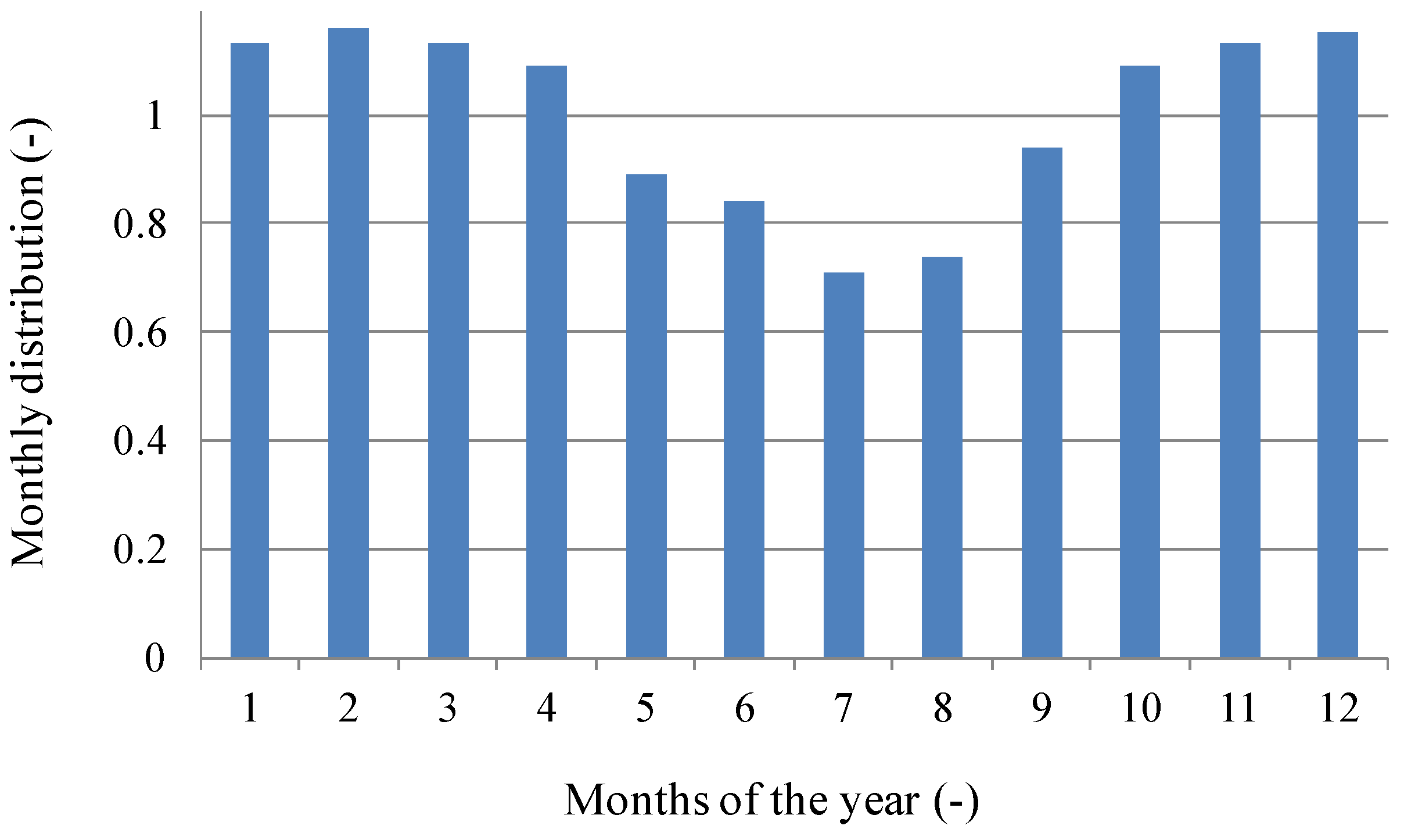
2.2. Domestic Hot Water Load in Swedish Single-Family Houses

A profile of the domestic hot water load consumption in Swedish single-family houses was created. The profile consists of seven different draw-offs during the day (Figure 1). This represents a simplification of the hourly profile described by Widén et al. [29] but scaled to the latest data on the Swedish average hot water consumption of 42 litres per person per day measured in 44 single-family houses [24,30]. A sensitivity analysis showed that using a more detailed draw-off profile would have a low impact on the results and would only increase the total computational time. The measured average cold water temperature in the taps was 8.5 °C [30]. The variation in consumption during the year was also introduced based on measured data [31] and is shown in Figure 2. Swedish statistics show that the average number of inhabitants in Swedish single-family houses is three [32]. Hence, assuming that hot water is heated up to 60 °C, the annual domestic hot water consumption in these houses was estimated to be 2050 kWh/year. This value is close to previous measured values in single-family houses [33]. This energy amount does not include the extra energy necessary to compensate for the heat losses from the storage and piping system and the energy necessary to run the circulation pump in the tank loop, if one is installed. These factors were taken into account by the model in calculating the annual solar fraction of every system.
Figure 1. Daily domestic hot water profile.
Energies 05 04110 g001
Figure 2. Yearly variation of the daily domestic hot water consumption.
Energies 05 04110 g002

2.3. Regulations Regarding Water Heating Systems and Legionella Growth

It is known that legionella bacteria grow between 20 °C and 50 °C with maximum growth between 32 °C and 42 °C and dies above 60 °C after a certain period of exposure [34,35,36]. E.U. directives concerning legionella prevention are very general. In EN 806-2 is stated that “the hot water temperature in the hot water pipe work shall not drop below 50 °C” [37]. Investigation during in Swedish and Italian hospitals during ten years showed that, in order to achieve safety from legionella danger, it is unrealistic and unnecessary to completely eliminate the bacteria [38,39]. Indeed, a thermal prevention does not offers 100% protection against legionella occurrence but prevents an uncontrolled bacteria growth [37]. From the literature review it is concluded that small systems like the ones designed for solar domestic hot water represent a very low risk for bacteria growth. In France, Germany, United Kingdom and Switzerland, the risk is considered very low in single-family houses and there are no restrictions on water storage temperature [34,37,40,41]. According to a theoretical study for the specific conditions in The Netherlands, a possible risk for legionella growth should not be excluded especially in case of absence during a week in the winter [34]. The Netherlands uses probably the most extensive risk assessment in Europe and recommends that a weekly thermal disinfection of 60 °C during 20 min is performed when the water is stored between 25 °C and 45 °C [25,37]. In such situation, “Legionella may occasionally occur in concentrations above the detection limit but there is no reason to expect high concentration levels [37]”. The Swedish industry regulations recommend that a weekly thermal disinfection is performed at 60 °C during 10 min if water is stored at lower temperatures than 60 °C [42,43]. Hence, according to the literature review and taking the following measures, the system should be well protected against a dangerous level of legionella growth:
  • Auxiliary heater volume kept at 60 °C;
  • Hot water temperature available at the higher than 50 °C and lower than 60 °C;
  • Heating up the whole storage volume to 60 °C during 20 min if the temperature of the retrofitted tank was below 60 °C during a period of one week;
  • As a design guideline, the domestic hot water system should, during a maximal period of six hours, be able to heat up 10 °C cold water and deliver two times 140 litres of 40 °C water in one hour. This is the equivalent to being able to provide, every six hours, 9.75 kWh during one hour.
All systems were designed in a way that these requirements/recommendations could be met.

2.4. System Model

The retrofitted system models range from simple connections to more advanced configurations and controls. However, the complexity was never increased to a level that would be technically difficult to build in practice. Also, it was decided to avoid design configurations that would predictably cause such a rise in the investment cost that it would be hardly recouped by the increase in energy savings. Each system model was built by using different component simulation models called TRNSYS types. These are:
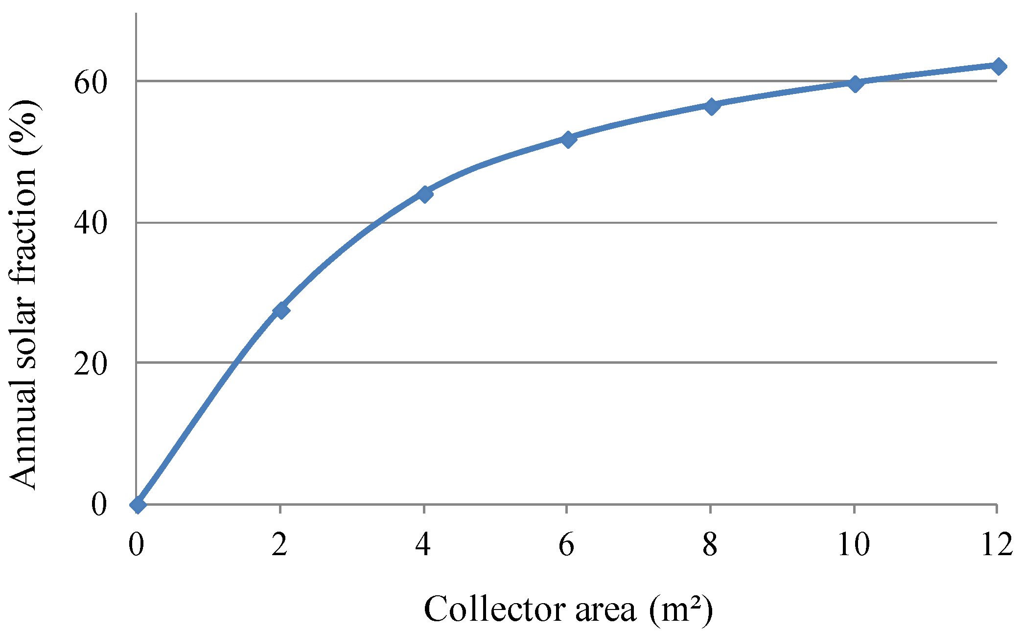
  • Thermal collector—type 537 from TESS TRSYS library [44]. This solar collector model operates like a conventional flat plate collector but makes it possible to regulate a variable speed for the pump in the collector loop in order to keep the outlet temperature, Tout, at a user-specified value. The parameters used to describe the collector were considered to be reasonable for flat plate collectors used in a cold climate [18,24]. These are 0.8 for F’(τα)n, −3.6 for F’U0, −0.014 for F’U1 and −0.2 for b0 based on average collector temperature and tested flow rate of 30 kg/h. The dependence of parameter kb(θ) on b0 is described by Equation (1) [19]. A sensitivity analysis was performed regarding the size of the collector and the corresponding annual solar fraction in the range 0–12 m2.
    K b ( θ ) = 1 b 0 × ( 1 cos θ 1 )
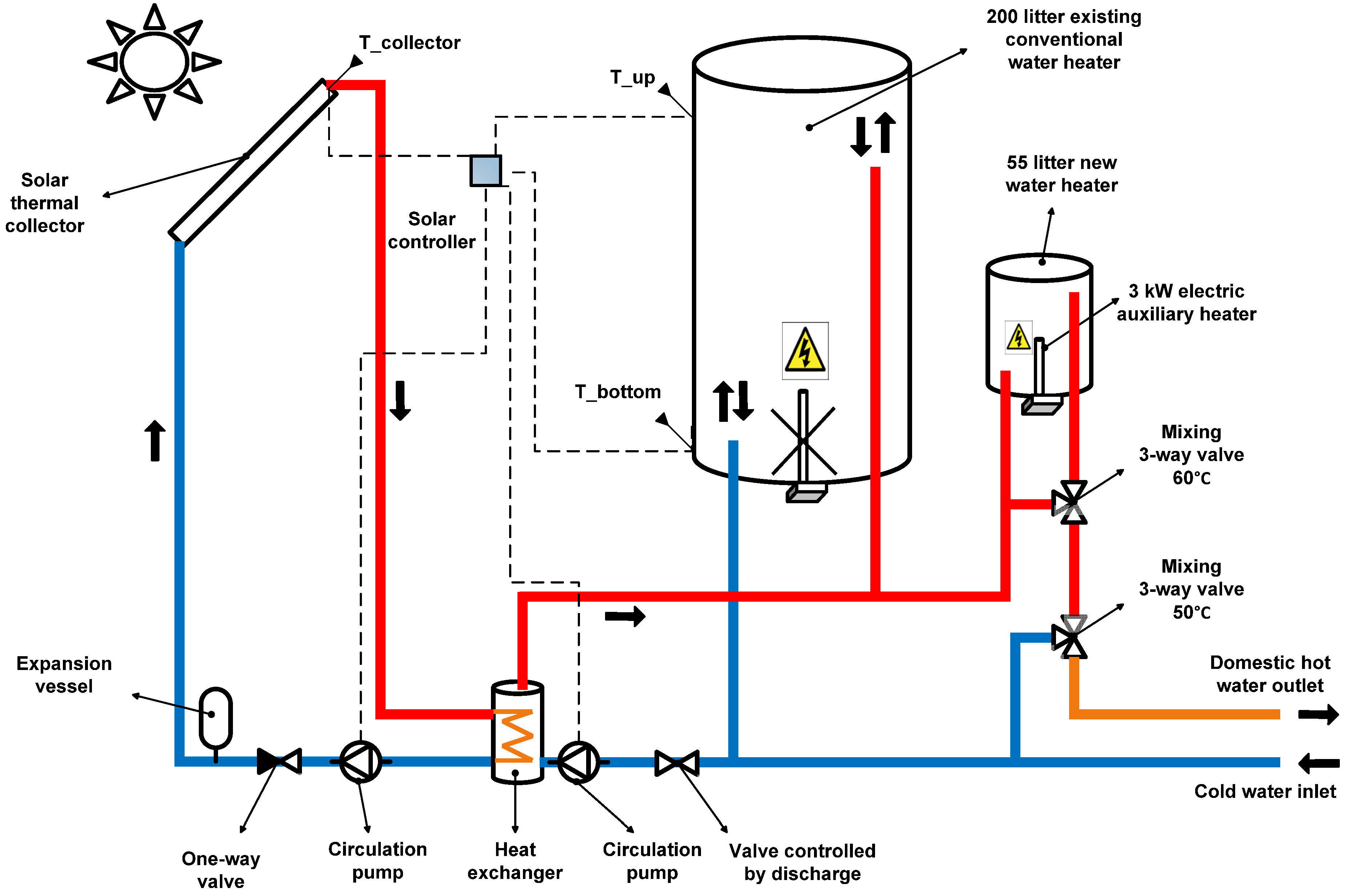
  • Fully stratified standard storage tank (6 nodes)—type 534 from TESS TRNSYS library. This model represents a common type of storage tank in standard SWH systems for domestic hot water production. The model divides the tank into isothermal nodes that thermally interact with the ones above, below and with the tank wall. It models a vertical cylindrical tank with a total volume of 255 litres and 1.60 m high. The coil heat exchanger was placed in the lower third of the tank according to the manufacturer’s specifications. A 3 kW electric auxiliary heater was fitted horizontally at 0.5 m from the top with a set-point temperature, Tset, of 60 °C (Figure 3). As shown by Cruickshank and Harrison [45], calculating the heat loss factor of the storage based on its insulation characteristics and materials can lead to significant errors. The number and type of inlet and outlet connections and poor insulation at the tank bottom are examples of factors that lead to such inaccuracies. Thus, the U-values were then based on the experimental results with common storages in standard SWH systems [45]. These were assumed to be 1 W/m2 °C for the top and middle of the storage, Utop, Uside and 2.5 W/m2 °C for the bottom, Ubottom;
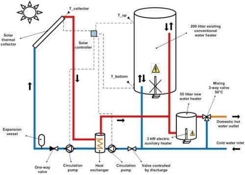
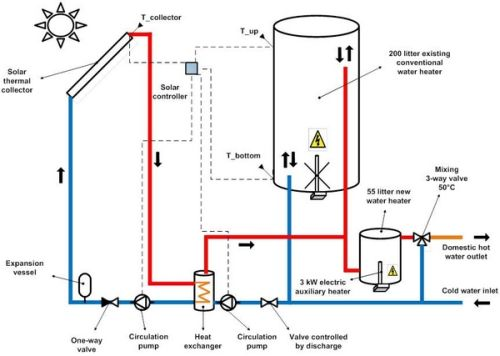
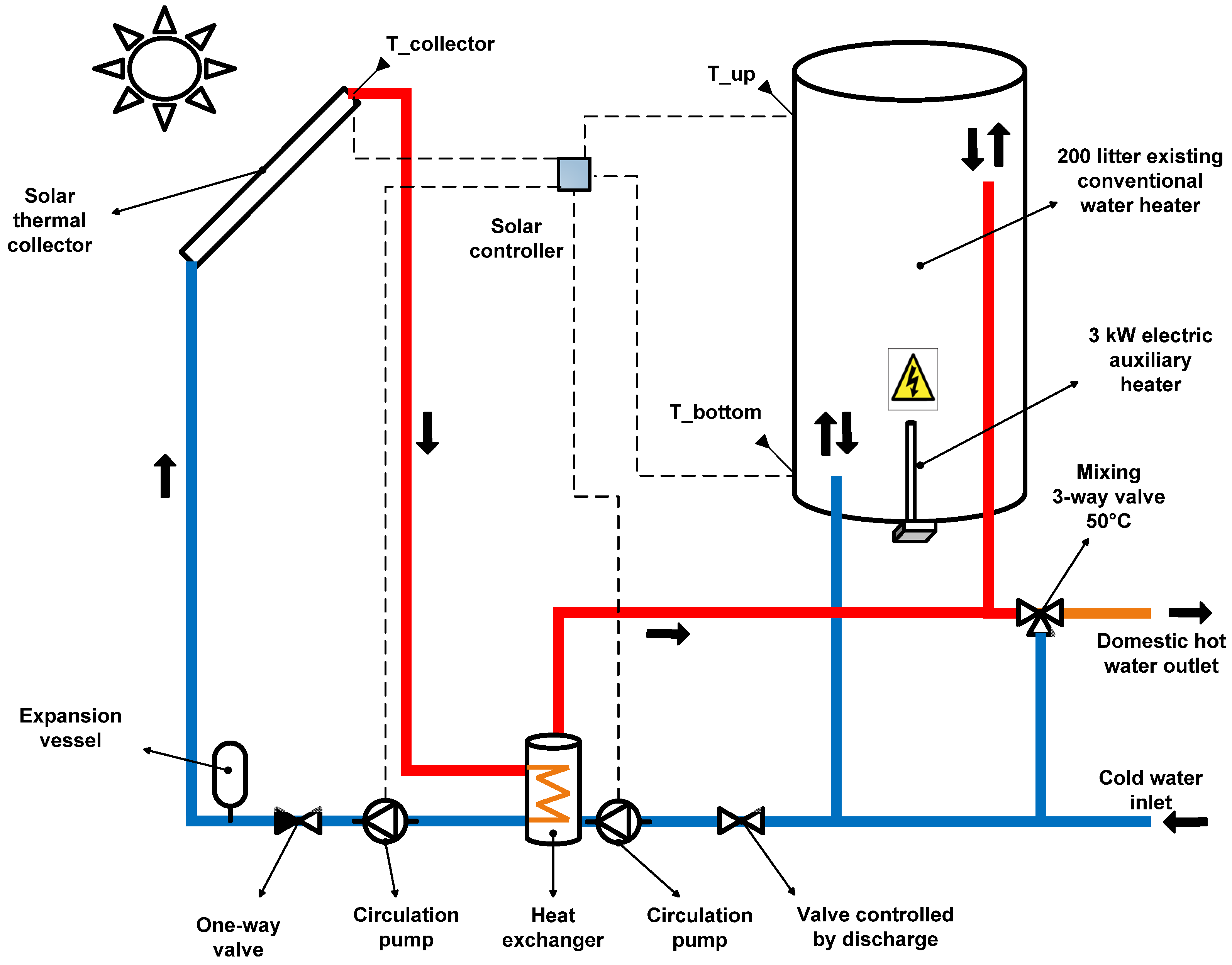
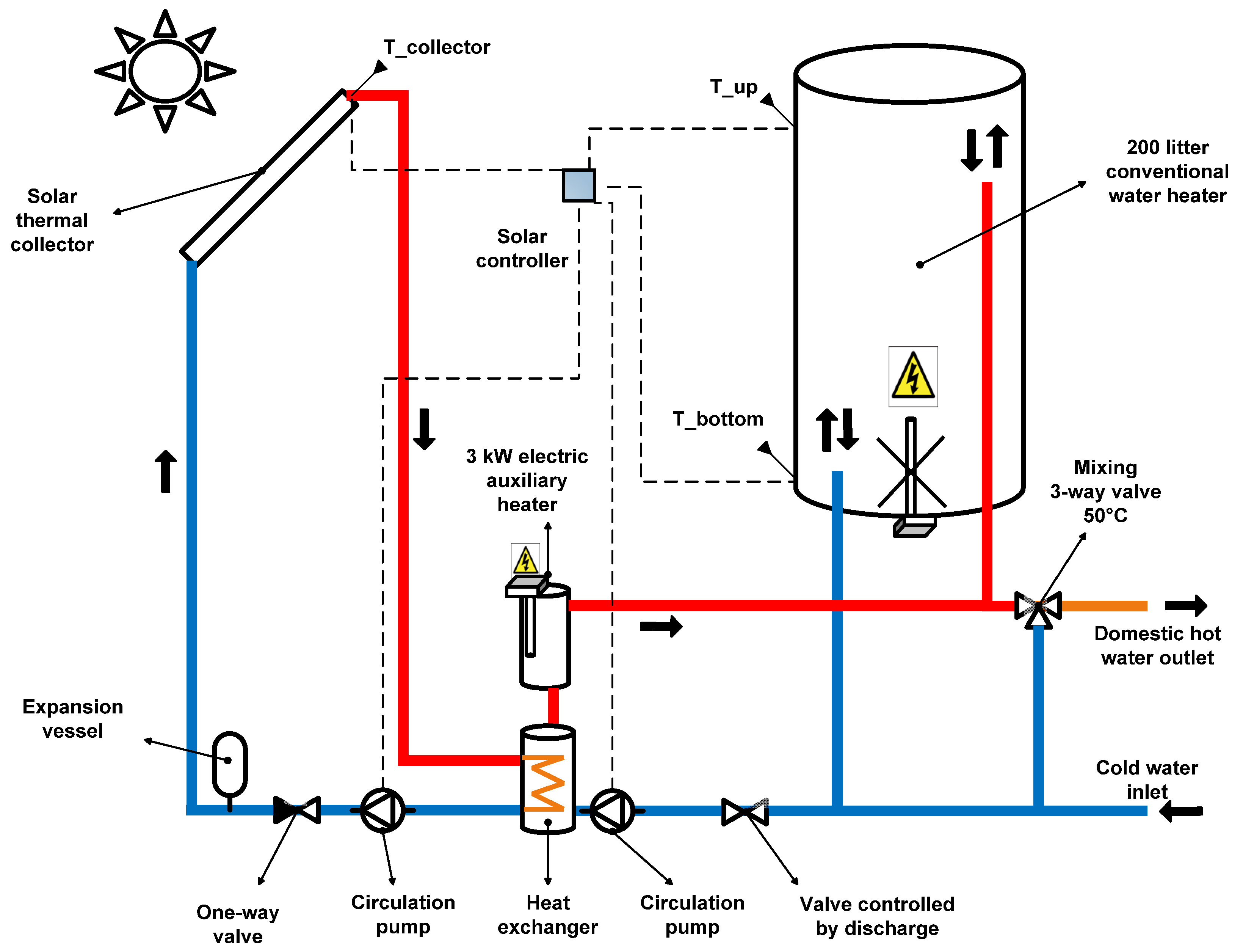
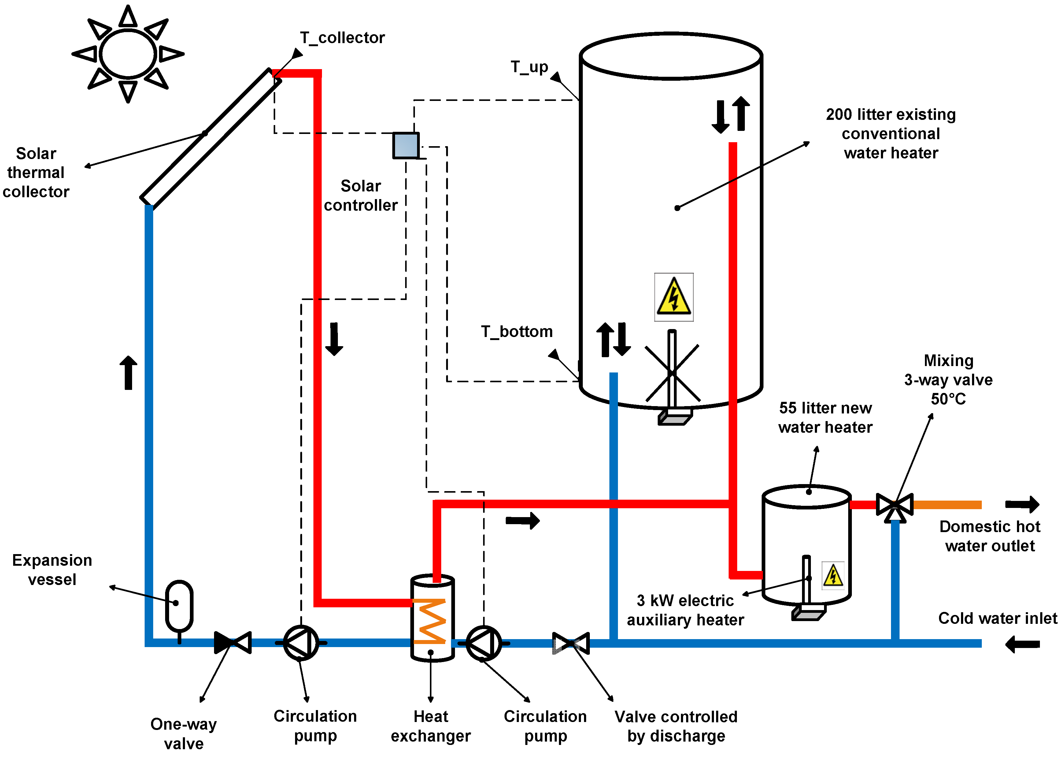
  • Fully stratified retrofitted storage tank (6 nodes)—type 534 from TESS TRNSYS library. This storage was modelled with the same principles as the standard storage for SWH systems. However, the total volume was set to 200 litres, the height was assumed to be 1.40 m, the connections are placed at the top and bottom of the tank (Figure 4, Figure 5, Figure 6 and Figure 7) and there is no internal heat exchanger. Only retrofitted system 2 uses the auxiliary heater placed at the bottom (Figure 4). In all the other systems this heater is disabled. The same U-values described above were also used for this storage;
  • Small heater storage tank (1 node)—type 534 from TESS TRNSYS library. The total volume was set to 55 litres and the height to 0.60 m. The connections are also placed at the top and bottom of the tank (Figure 5, Figure 6 and Figure 7). An auxiliary heater of 3 kW was used in all models since this is the most common and a higher power could create problems with the installed capacity in such houses. The auxiliary heater keeps the temperature of the storage volume at least at 60 °C to avoid legionella problems [46]. The average U-value used for this storage was 0.5 W/m2 °C based on preliminary measurements on an existing tank. A sensitivity analysis concerning the impact on the annual solar fraction of the variation in the auxiliary heater volume and temperature was performed;
  • External heat exchanger—type 5b, counter flow (Figure 4, Figure 5, Figure 6 and Figure 7). A sensitivity analysis was performed to investigate the influence of the heat exchanger capacity on the annual solar fraction in the interval 0–600 W/K. Since the effect of glycol percentage in the anti-freeze solution of the collector circuit was previously shown to have small impact on the annual solar fraction [18], the Cp of water, 4.19 kJ/kg K, was used instead. The flow speed was set equal on both sides of the heat exchanger;
  • Circulation pumps—type 3b, single speed. In all the systems the flow was optimized in order to maximise the annual solar fraction;
  • Controller—type 2b, ON/OFF differential controller. The controller turns ON both the pumps when the difference between the outlet collector temperatures, Tout, and the bottom tank temperature, Tbottom, is higher than 10 °C. The charging process is ceased when this difference is lower than 3 °C. The charging is also stopped if the temperature at the top of the tank, Ttop, reaches 100 °C.
  • Radiation processor—type 109-TMY2 used to compute the radiation and weather data for Lund, Sweden (latitude 55°44'N, longitude 13°12'E);
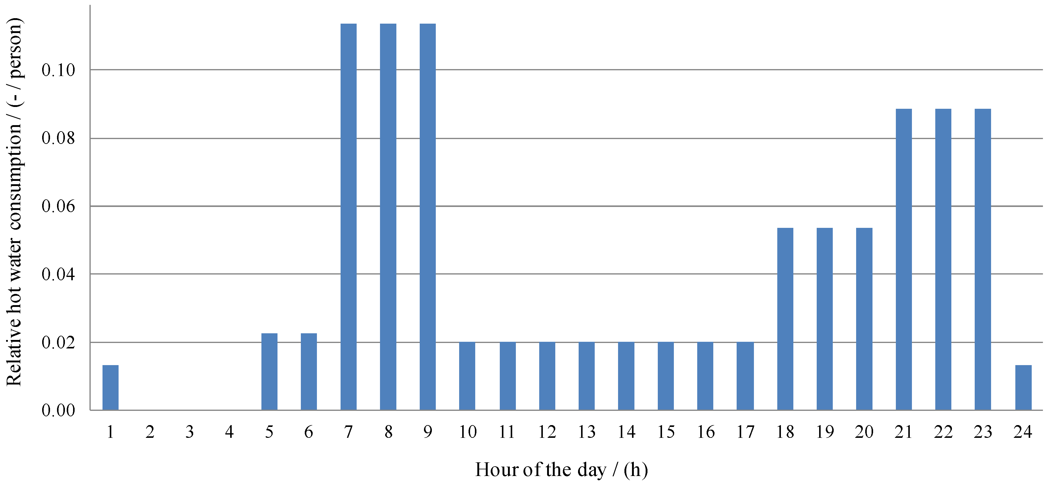
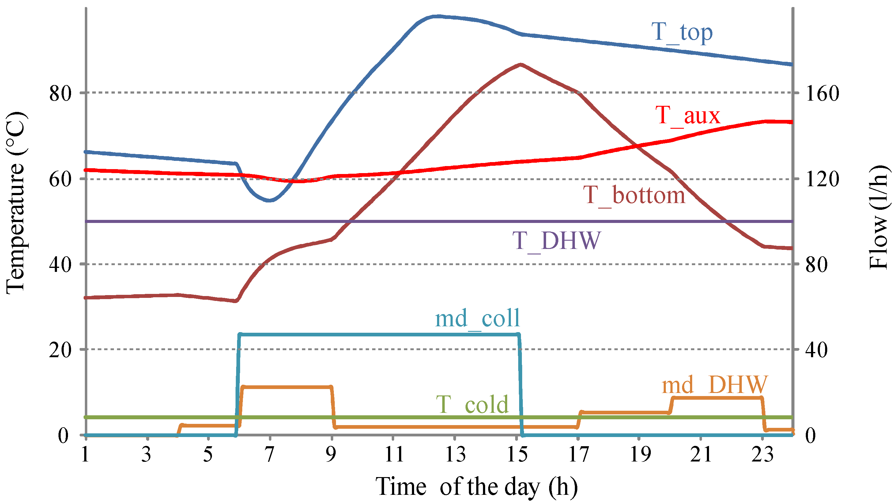
  • Domestic hot water load profile—type 14 used to generate the daily load profile (Figure 1);
  • Energy balance check—type 28 with energy balance check based on Buckles and Klein [17] for every simulation time-step, t, of six min.
A summary of the design parameters used in the system model are presented in Table 1.
Table 1. Design parameters for the system model.
ParameterValue
Ac0–12 m2
F’(τα)n0.8 (−)
F’U0−3.6 W/m2 K
F’U1−0.014 W/m2 K2
b00.2 (−)
β40 °
m / ˙ A c 0–11 kg/h m2
Ppump60 W
Upipe0.8 W/m2 K
lout8 m
lin8 m
HXcapacity0–600 W/K
Tset60–90 °C
Vaux55–75 L
Utop1 W/m2 K
Uside1 W/m2 K
Ubottom2.5 W/m2 K
The annual solar fraction takes into account the energy to produce the domestic hot water required by the load including losses and necessary energy to run pumps as well as the saved energy by the collectors. It was calculated based on Equation (2) [17].
f = Q a u x n o n s o l a r   Q a u x s o l a r     Q p u m p s Q a u x n o n s o l a r = 1   Q a u x s o l a r +   Q p u m p s Q a u x n o n s o l a r

2.4.1. Solar Collectors and Flow Control

The solar collectors were placed at a 40° tilt from horizontal which maximises the annual solar fraction in Lund, Sweden [47]. A sensitivity analysis was performed regarding the impact of the size of the collector array on the annual solar fraction. Once the size was determined the collector field area in all systems was kept constant in order to ensure that any difference in annual performance was caused by the system configuration and/or control. Two types of pump control were tested. Control (a) varies the flow up to 300 kg/h so that the collector outlet temperature was kept constant and equal to 65 °C. Control (b) consists of constant flow speed and is set to a value that maximises the annual solar fraction. The optimization process for control (b) was performed using Generic Optimization Program (GenOpt) [48] applied to TRNSYS. The Hooke-Jeeves algorithm [49] was used to perform iterations with different flow values until the maximum annual solar fraction of each system was reached.

2.4.2. Standard System

A model of a standard solar thermal system was created which is described by the sketch in Figure 3. The storage volume is 255 litres in order to match the volume of the retrofitted system with the highest performance (retrofitted system 3, Figure 6). There are three temperature sensors that control the pump, two placed on the tank’s surface and the other at the collector outlet.
Figure 3. Standard solar water heating system.
Energies 05 04110 g003

2.4.3. Retrofitted System 1

Figure 4 describes a simple and direct way of assembling the solar collectors to the existing water heaters. Also, two temperature sensors are placed on the surface of the retrofitted tank in order to control both the collector pump and the tank pump. As exemplified in Figure 3, solar storages are specially designed for solar thermal applications with, at least, two connections for the domestic hot water loop and two others for the solar collector loop. Contrarily, conventional tank heaters have only two connections for domestic hot water. The working period of the pump placed in the tank loop must be controlled with the domestic hot water draw-offs so they do not coincide. When no hot water is required, the pump is able to charge the tank. When draw-offs take place, both the pump and the control valve are shut down and the incoming cold water is pressed in the bottom of the tank replacing the outgoing domestic hot water at the top. In this system the whole tank is constantly heated up to 60 °C by the auxiliary heater placed at the bottom. This means that, for this system, running the system with control a) in order to have a constant outlet temperature of 65 °C does not make sense.

2.4.4. Retrofitted System 2

In this system, a new 3 kW auxiliary heater is added to the side-arm heat exchanger while the existing one at the bottom of the tank is turned OFF (Figure 5). The aim is to achieve stratification in the storage. The heater and the pump on the tank loop are turned ON when Ttop falls below Tset minus the dead band. Consequently, the cold water in the tank bottom flows through the heat exchanger and is heated up in the side-arm heater before entering the top of the tank. The heater is turned off when Ttop is higher than Tset plus the dead band.
Figure 4. Retrofitted system 1—simple retrofitting of existing hot water heaters.
Energies 05 04110 g004
Figure 5. Retrofitted system 2—retrofitted system with auxiliary heater on the side-arm.
Energies 05 04110 g005

2.4.5. Retrofitted System 3

In retrofitted system 3, a 55 litre auxiliary heater storage was series connected to the existing storage (Figure 6). This means that the retrofitted storage tank is now exclusively used for solar hot water which is not stored together with hot water provided by the auxiliary heater. When hot water is drawn off by the user, the water at the top of the retrofitted storage is pushed to the bottom of the small heater and from there to the user. When the temperature in the auxiliary heater becomes higher than Tset due to the incoming solar hot water, the auxiliary heater is turned OFF automatically by the thermostat.
Figure 6. Retrofitted system 3—retrofitted system with an additional tank heater connected in series.
Energies 05 04110 g006

2.4.6. Retrofitted System 4

The last retrofitted system consists of adding one mixing valve in the previous system (Figure 7). The valve makes it possible to mix flows from two inlets into one outlet. The cold source inlet is the retrofitted storage while the hot source inlet is the auxiliary storage. In order to minimize the risk of legionella growth the outlet temperature of the valve was set to 60 °C. If both the inlet temperatures are higher than 60 °C the water is taken from the retrofitted tank only and later cooled down to 50 °C by the last mixing valve before going to the load.
For this system, not only controls (a) and (b) for the flow of the pump were analysed but also an extra control, control (c). The latest consists on shutting down the auxiliary heater whenever the solar storage is able to provide a volume of water equal to that of the auxiliary heater, heated up to 60 °C or higher. When the temperature of that volume drops below 60 °C, the water in the auxiliary volume is heated up again and ready to provide the necessary hot water to the load.
Figure 7. Retrofitted system 4—retrofitted system with an additional mixing valve.
Energies 05 04110 g007

3. Results and Discussion

3.1. Standard System

3.1.1. Collector Area

The sensitivity analysis of the collector area is presented in Figure 8. The collector area was set to 6 m2 since it represents a balance between a high annual solar fraction and collector area. The chosen collector area is not a determinant factor on comparing the different systems based on their system configurations, types of storage and control strategies. Different collector areas would impact the absolute value of the annual solar fraction but not the relative performances between the systems.

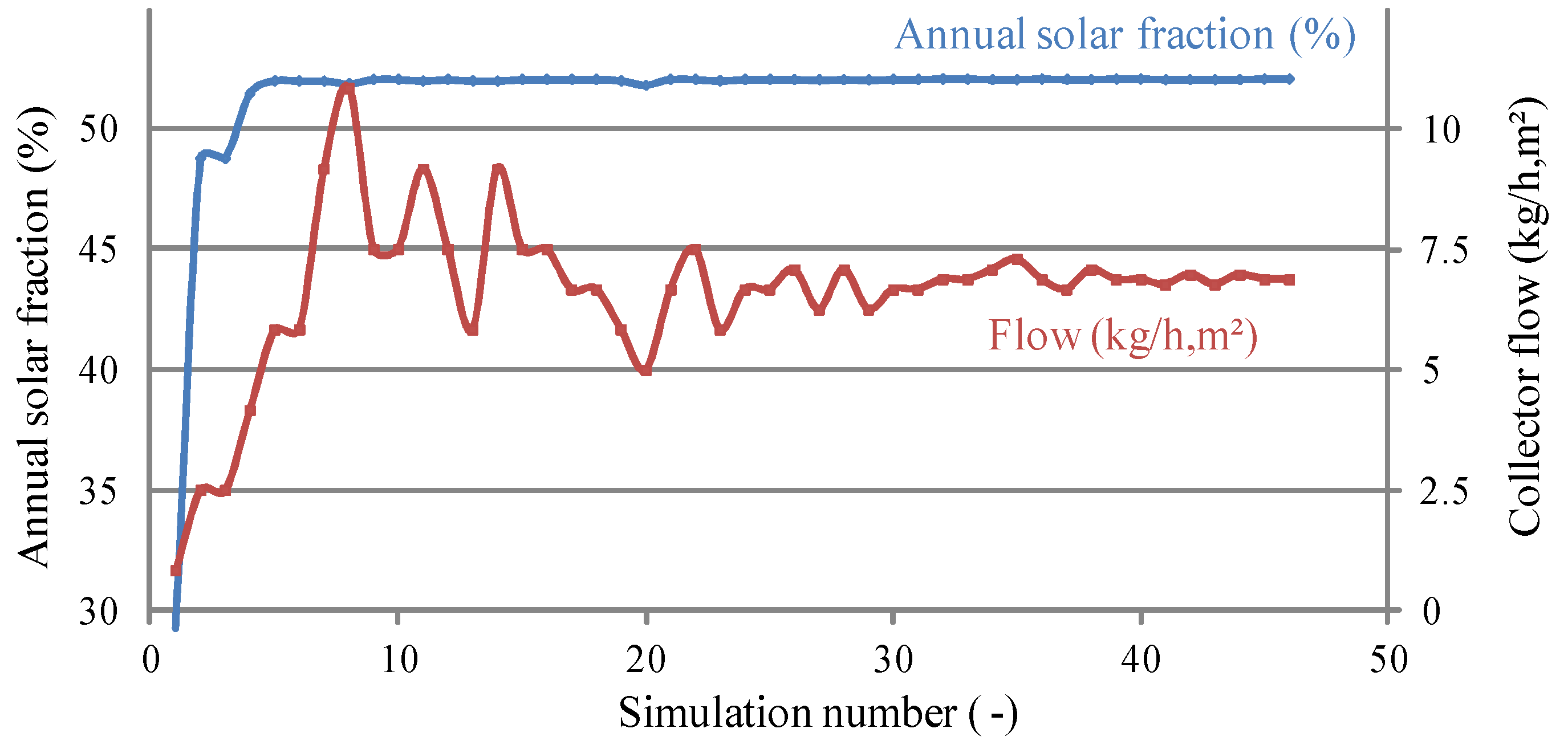
3.1.2. Mass Flow Rate

The mass flow rate per collector area ( m ˙ / A c ) was optimized for each system using GenOpt. The optimizing results for the standard system are shown in Figure 9. As shown in the figure, for the flow interval of 5–10.8 kg/h m2 the annual solar fraction is kept at its maximum, 52%, within a 1% deviation. The flow used in all systems was 7 kg/h m2 which ensures maximum annual solar fraction. Such low flow value is in agreement with previous studies where comparable flow rates were found to increase the annual performance [23,50,51,52]. Furthermore, the requirement on the size of components in low flow systems is reduced. This is the case of the heat exchanger capacity, pipe diameter, pump sizes and their energy consumption [2,12,50]. The annual solar fraction result is in accordance with previous studies for the same kind of standard SWH systems with comparable collector area, storage type, storage volume, mean domestic hot water load and weather conditions [18,53].
Due to the position of the auxiliary heater, the total auxiliary volume is 102 litres. In order to reach the recommended design guideline for large loads the heater temperature should be temporarily increased to 70 °C by the user.
Figure 8. Variation of the annual solar fraction with the collector area.
Energies 05 04110 g008

3.2. Retrofitted System 1

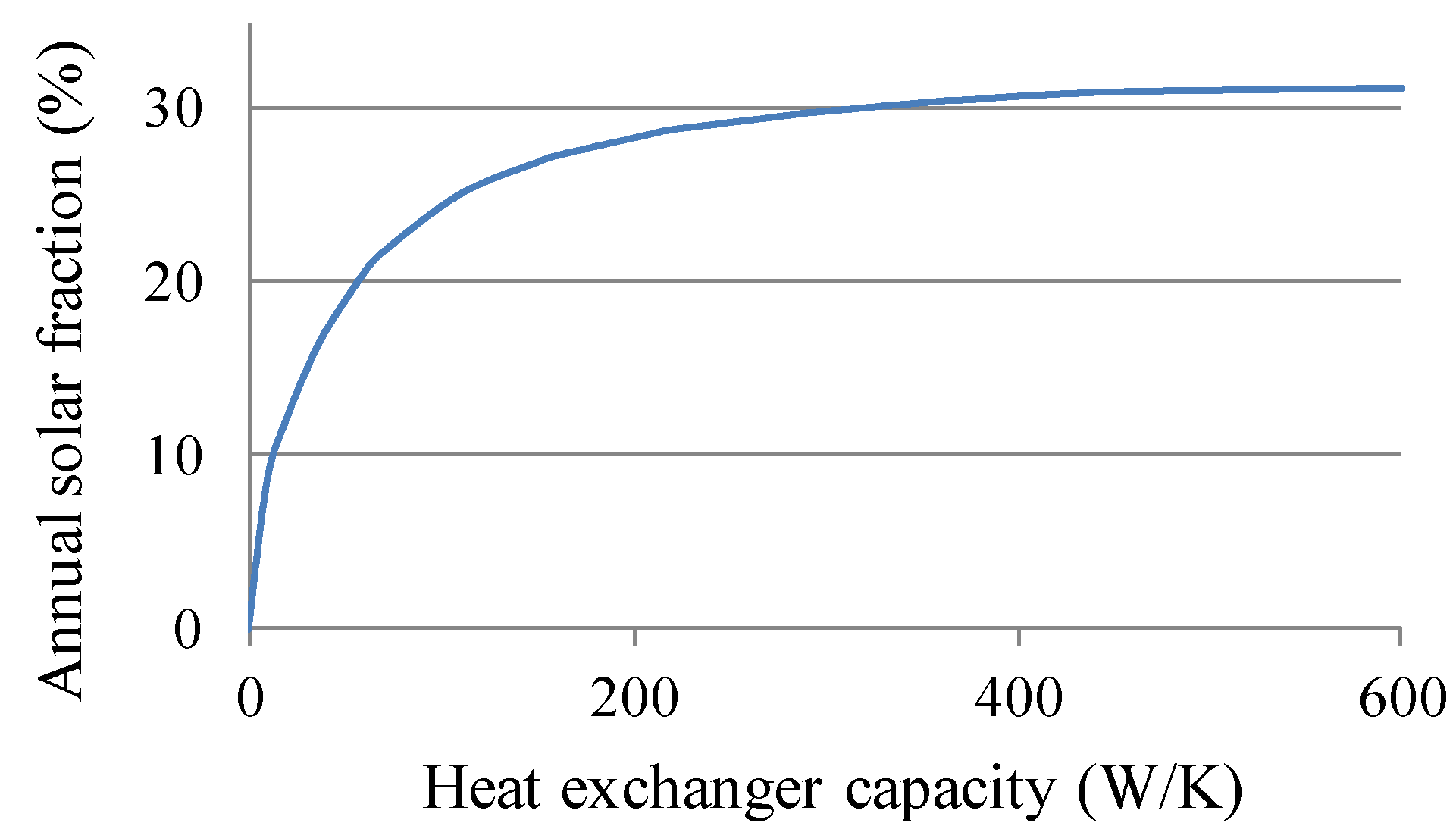
3.2.1. Heat Exchanger Capacity

The influence of the heat exchanger capacity on the annual solar fraction was investigated (Figure 10). The capacity for the heat exchanger was set to 300 W/K which ensures an annual solar fraction of 28.9%. This value represents 95% of the achieved annual solar fraction if the heat exchanger capacity was doubled. The heat exchanger capacity of 300 W/K was kept constant in all systems.
Since the auxiliary is placed at the bottom, the whole tank represents the auxiliary volume when solar energy is not available, which ensures that the design guideline for large loads is met.

3.3. Retrofitted System 2

For this system, simulation results show that the annual solar fraction increases to 34.8% for control (a) and 37.6% for control (b). However, stratification is limited by the fact that the auxiliary hot water is pumped inside the tank, inducing mixing. Also, heat diffusion and wall conduction in the storage limit the stratification level. Furthermore, the energy needed for the pump increased significantly to 243 kWh/year which is 3.5 times higher than that of the previous system. This is explained by the fact that one more pump is needed and that one of them works continuously every time auxiliary heat is required. Running the system with control (a) prevents disruption of stratification since the top of the tank is heated up to 60 °C and the collector outlet temperature is always higher than 65 °C. However, this increases significantly the collector losses and control (b) was shown to be more efficient.
In this system the auxiliary volume is the volume above the temperature sensor in the upper part of the tank which was set to 80 litres. This volume meets regular loads while design loads are met by temporarily increasing the auxiliary heater temperature to 90 °C or by turning ON the existing auxiliary heater in the bottom of the storage.
Figure 9. Convergence of the optimization algorithm of the annual solar fraction by varying the collector flow.
Energies 05 04110 g009
Figure 10. Variation of the annual solar fraction, for system 1, with the heat exchanger capacity.
Energies 05 04110 g010

3.4. Retrofitted System 3

The estimated annual solar fraction for retrofitted system 3 is 38.1% for control (a) and 50.5% for control (b). Since the auxiliary heater is placed in another tank, it is no longer turned ON when the outlet temperature of the collector is below 60 °C. Also, the retrofitted tank works at lower temperatures which increases the collector working hours and efficiency. In addition, the new well insulated hot temperature tank provides the extra energy when solar energy is not available. Having the larger tank working at lower temperatures reduced the retrofitted storage heat losses by 50%, 457 kWh/y (Table 5). Furthermore, mixing caused by diffusion and wall conduction was also considerably reduced since the auxiliary hot water at 60 °C is not stored in the same tank as the cold water from the main. The system “stratification” is then achieved by means of two tanks with low stratification levels but working at different average temperatures.
During the summer period, when solar hot water is available over 60 °C, the total solar hot water storage volume of the series connected system is increased to 255 litres, since both tanks are connected in series and no auxiliary energy is needed. Figure 11 shows such a typical operation day in July where the collector is charging the system simultaneously as the user is discharging the tank. As shown in the figure, both the retrofitted storage tank and auxiliary storage are charged during a sunny morning until the middle of a cloudy afternoon. From that point on, the pumps were stopped while the discharge process continued. At the beginning of the charging process it is possible to notice that stratification decreases since colder temperature is placed at the top. This is explained by the fact that the inlet position is placed at the top while the controller compares the bottom temperature with the collector outlet temperature in order to start the pumps. This controlling process will be improved and tested in practice. After the solar pump is stopped the discharge of the retrofitted storage continues cooling down the bottom of the tank.
Figure 11. Typical operation day of retrofitted system 3 during the summer period.
Energies 05 04110 g011
The sensitivity analysis on the auxiliary volume and temperature variation is presented in Table 2 and Table 3. The annual solar fraction remains almost constant with auxiliary volume variation. For larger auxiliary volumes, the domestic hot water load increases due to higher losses. However, the solar coverage increases proportionally and the annual solar fraction remains almost constant. On the other hand, the increase in Tset caused a significant decrease in solar fraction. The domestic hot water load increases due to higher thermal losses in the auxiliary heater. For higher values of Tset less water is required from the auxiliary heat source and, since the tanks are series connected, from the retrofitted solar storage. Hence, the average temperature of the retrofitted storage becomes higher which decreases the solar contribution and increases the heat losses.
The 55 litre tank heated to 60 °C meets regular loads. When the temperature in the main is 8.5 °C, it corresponds to 92 litres mixed water at 40 °C provided to the user. When Tset is increased to 90 °C and, if the solar storage is discharged, the design guideline for large loads is met by 85% of the total energy. To meet this recommended design load to 100% the user can temporarily turn ON the existing auxiliary heater of the retrofitted tank. Alternatively, the 75 litre auxiliary volume heated up to 90 °C covers that demand to 100%.
For the present conditions, simulation shows that it was necessary to use the thermal disinfection measure 18 times during a year and that the annual solar fraction was decreased less than 3%.
Table 2. Annual solar fraction calculations for three auxiliary volume sizes of retrofitted system 3 with Tset = 60 °C.
Vaux (L)Qaux-nonsolar (kWh/y)Qaux-solar (kWh/y)Qpumps(kWh/y)Qlosses-retrofit (kWh/y)Qlosses-aux (kWh/y)Annual Solar Fraction (%)
55203787713144714850.5
65205388513144516350.5
75207090113144617950.1
Table 3. Annual solar fraction calculations for different auxiliary heater temperatures of retrofitted system 3 with Vaux set to 55 L.
Tset (°C)Qaux-nonsolar (kWh/y)Qaux-solar (kWh/y)Qpumps (kWh/y)Qlosses-retrofit (kWh/y)Qlosses-aux (kWh/y)Annual Solar Fraction (%)
60203787713144714850.5
702088100712747717645.7
802138114812250820840.6
902188129611853824435.4

3.5. Retrofitted System 4

The estimated annual solar fraction for retrofitted system 4 is 36.9% for control (a), 48.2% for control (b) and 49.0% for control (c). As shown, control (c) increased the annual solar fraction by less than 1%. When the auxiliary heater is turned OFF, the temperature drops due to heat losses. When it is turned back ON it again heats up the volume to 60 °C to compensate for the heat losses during that period. The difference between shutting down the heater during certain periods and compensating for the heat losses continuously by maintaining its temperature constant at 60 °C was shown not to be significant.
The fact that the achieved performance is lower than that of the previous system is explained by the fact that, during intervals where Tsolar > Tset, the total solar hot water storage volume is not increased since water does not go through the auxiliary heater storage. If the additional mixing valve were replaced by an electronic rotating valve that allowed that to happen, the total maximum increase would be 2% for Tset = 70 °C and would decrease proportionally with the increase in Tset. It was then assumed that such a small saving would hardly compensate for the extra costs of this special control valve.
At Tset = 60 °C the system works like retrofitted system 3 and therefore a sensitivity analysis on the auxiliary volume would show the same results. On the other hand, the increase in Tset shows different results (Table 4). In retrofitted system 3, for higher values of Tset, less water is required from the auxiliary storage and therefore from the retrofitted storage. On the contrary, increasing Tset in retrofitted system 4 does not have the same effect since water is required from the retrofitted storage both to the mixing valve and to the auxiliary storage. Thus, the discharge rate of the retrofitted storage is not significantly changed and, consequently, neither are the heat losses or the solar contribution. Hence, the decrease in solar fraction is not so abrupt and is mostly the result of the increase in heat losses in the auxiliary storage. Also in this system, the design guideline for large loads is met as described previously in retrofitted system 3.
Table 4. Annual solar fraction calculations for different auxiliary heater temperatures of retrofitted system 4 with Vaux set to 55 L.
Tset (°C)Qaux-nonsolar (kWh/y)Qaux-solar (kWh/y)Qpumps (kWh/y)Qlosses-retrofit (kWh/y)Qlosses-aux (kWh/y)Annual Solar Fraction (%)
60204293012946113548.2
70208199212847017146.2
802120103012847020845.4
902161106812847024444.6
As shown in Table 2, Table 3 and Table 4, the performance of retrofitted system 3 and 4 present marginal differences. The series connected system, retrofitted system 3, achieves the highest annual solar fraction but is also the most sensitive to Tset. This result indicates that the size of the auxiliary storage should be well designed according to the load so that increases in its temperature are not often needed. In case of big uncertainties in the real domestic hot water load, retrofitted system 4 is more suitable since the decrease in performance is less sensitive to storage temperature increase during long periods. The costs of the two systems are almost identical.

3.6. Standard and Retrofitted Systems

A summary of the annual solar fraction calculations and heat losses in the storages for all systems is presented in Table 5. How well the simulation results describe reality depends on several factors assumed for this study. Some of these are: the performance of the solar collector array, the U-values of the storages, losses by wall conduction, stratification levels, the design and position of inlets and outlets, flow induced mixing, heat losses of pipes and heat exchanger. As all retrofitted systems were built using the same components, inaccuracies that occur in one system model tend to occur in the same way in the others. This makes it significantly more reliable to draw conclusions about the relative performances of the systems. In a future analysis model validation and a detailed economic investigation will be carried out.
Table 5. Annual solar fraction calculations for all systems.
System nameQaux-nonsolar (kWh/y)Qaux-solar (kWh/y)Qpumps (kWh/y)Qlosses-retrofit/Qlosses-stnd (kWh/y)Qlosses-aux (kWh/y)Annual Solar Fraction (%)
Standard system (a)2397123892648(-)44.5
Standard system (b)2397109060779(-)52.0
Retrofitted system 1 (b)3105213475973(-)28.9
Retrofitted system 2 (a)35072002286886(-)34.8
Retrofitted system 2 (b)35071945243904(-)37.6
Retrofitted system 3 (a)2037107418736914538.1
Retrofitted system 3 (b)203787713144714850.5
Retrofitted system 4 (a)2042110818139213536.9
Retrofitted system 4 (b)204293012946113548.2
Retrofitted system 4 (c)204291412946112349.0
Housing all the retrofitting components, controls and required valves in one add-on unit which is then connected to the existing heater, the collectors and the user may reduce the complexity and cost of the installation.

4. Conclusions

Four different system configurations on how to retrofit existing domestic hot water heaters in single-family houses in Sweden were theoretically analysed. The simulation results quantify the impact of the different configurations and control strategies on the annual solar fraction for one set of reference conditions. From the simulation results it was concluded that it is appropriate to use forced circulation and an external heat exchanger for the retrofit. Hence, the performance of the retrofit is not dependent on the tank loop configuration or on the type of existing tank which is being retrofitted.
A high performance (high F’(τα)n and low F’U) solar collector array of 6 m2 is appropriate for the Swedish climate and domestic hot water load. For such collector area, low mass flow rates in the range of 5–10.8 kg/h m2 maximise the annual solar fraction. Consequently, the requirement on component sizes such as the heat exchanger capacity, pipe diameter, pump size and its energy consumption is reduced. Hence, the cost of the retrofit can be further reduced. A heat exchanger capacity of 300 W/K was found to be adequate to ensure that 95% of the maximum annual solar fraction is achieved.
The annual solar fraction of the retrofitted systems ranges from 28.9% to 50.5%. The retrofit configuration achieving the highest annual performance of 50.5% consists of using the retrofitted tank for solar hot water storage and connecting it in series with a new small auxiliary heater storage tank. Hence, the larger tank works at lower average temperatures while the new smaller and well insulated tank works at higher average temperatures. This increases the solar contribution and reduces the heat losses. The annual solar fraction achieved by a stand-alone standard solar thermal system with the same collector area, storage volume and reference conditions is 52%. Hence, the performances of both systems are comparable while the retrofitted system has the potential to have a lower investment cost. In the future, a model validation and a detailed economical assessment for a Swedish case study will be performed.

Acknowledgments

This study was supported by a Marie Curie program, SolNet—Advanced Solar Heating and Cooling for Buildings—the first coordinated international PhD education program on Solar Thermal Engineering.

Nomenclature

Tset
Temperature setting of the auxiliary heater (°C)
Tout
Collector outlet temperature (°C)
Ttop
Solar hot water temperature in the upper part of the retrofitted tank (°C)
Vaux
Volume of the auxiliary heater storage (L)
β
Collector slope from horizontal (°)
F’(τα)n
Zero loss efficiency of the collector (-)
F’U0
Heat loss factor (W/m2 K)
F’U1
Temperature dependence of the heat loss factor (W/m2 K2)
F’U
Total heat loss factor (W/m2 K)
kb(θ)
Beam incidence angle modifier as a function of θ(-)
b0
Calibration factor for kb(θ)
θ
Angle of incidence on the collector normal (°)
t
Simulation time-step (h)
Utop
Average heat loss factor for the top of the storage (W/m2 °C)
Uside
Average heat loss factor for the edges of the storage (W/m2 °C)
Ubottom
Average heat loss factor for the bottom of the storage (W/m2 °C)
Upipe
Average heat loss factor for the piping (W/m2 °C)
lout
Total length of the pipes exposed to outdoor temperature (m)
lin
Total length of the pipes exposed to indoor temperature of 20 °C (m)
Cp
Specific heat of water (J/kg K)
HXcapacity
Capacity of the heat exchanger (W/K)
Ppump
Maximum pump power (W)
m ˙
Mass flow rate (kg/h)
Ac
Collector area (m2)
Qaux-nonsolar
Required auxiliary energy to meet the load without solar collectors (kWh/y)
Qaux-solar
Required auxiliary energy to meet the load with solar collectors (kWh/y)
Qpumps
Required energy to run all the pumps in the system (kWh/y)
Qlosses-retrofit
Thermal losses from the retrofitted storage (kWh/y)
Qlosses-aux
Thermal losses from the auxiliary storage (kWh/y)
Qlosses-stnd
Thermal losses from the standard solar storage (kWh/y)
T_top
Temperature at the top of the retrofitted storage (°C)
T_bottom
Temperature at the bottom of the retrofitted storage (°C)
T_aux
Temperature at the new auxiliary heater storage (°C)
T_DHW
Temperature of the domestic hot water provided to the user (°C)
T_cold
Temperature of the cold water from the main (°C)
md_coll
Mass flow rate at the solar collector circuit (L/h)
md_DHW
Mass flow rate of the domestic hot water provided to the user (L/h)

References

  1. Hang, Y.; Qu, M.; Zhao, F. Economic and environmental life cycle analysis of solar hot water systems in the United States. Energy Build. 2012, 45, 181–188. [Google Scholar] [CrossRef]
  2. Dayan, M. High Performance in Low Flow Solar Domestic Hot Water Systems. Master’s Thesis, University of Winsconsin, Madison, MI, USA, 1997. [Google Scholar]
  3. Tsilingiris, P.T. Design and performance of large low-cost solar water heating systems. Renew. Energy 1996, 9, 617–621. [Google Scholar] [CrossRef]
  4. Eicker, U.; Pietruschka, D. Design and performance of solar powered absorption cooling systems in office buildings. Energy Build. 2009, 41, 81–91. [Google Scholar] [CrossRef]
  5. Swedish Energy Agency. Energy Statistics for Single-Family Houses; Swedish Energy Agency: Stockholm, Sweden, 2010.
  6. Cruickshank, C.A.; Harrison, S.J. Analysis of a Modular Thermal Storage for Solar Heating systems. In Proceedings of the Joint Conference of the Canadian Solar Buildings Research Network and Solar Energy Society of Canada Inc. (SESCI), Montreal, Canada, 2004.
  7. Cruickshank, C.A.; Harrison, S.J. Experimental Characterization of a Natural Convection Heat Exchanger for Solar Domestic Hot Water Systems. ASME Conf. Proc. 2006, 425–431. [Google Scholar]
  8. Cruickshank, C.A.; Harrison, S.J. Thermal response of a series- and parallel-connected solar energy storage to multi-day charge sequences. Sol. Energy 2011, 85, 180–187. [Google Scholar] [CrossRef]
  9. Qin, L. Analysys, modeling and optimum design of solar domestic hot water systems. Ph.D. Thesis, Danish Technical University, Copenhagen, Danmark, 1998. [Google Scholar]
  10. Fraser, K.F.; Hollands, K.G.T.; Brunger, A.P. An empirical model for natural convection heat exchangers in SDHW systems. Sol. Energy 1995, 55, 75–84. [Google Scholar] [CrossRef]
  11. Morrison, G.L.; Tran, H.N. Simulation of the long term performance of thermosyphon solar water heaters. Sol. Energy 1984, 33, 515–526. [Google Scholar] [CrossRef]
  12. Ogueke, N.V.; Anyanwu, E.E.; Ekechukwu, O.V. A review of solar water heating systems. J. Renew. Sustain. Energy 2009, 1, 106–121. [Google Scholar] [CrossRef]
  13. Abdul-Jabbar, N.K. Forced versus natural circulation solar water heaters: A comparative performance study. Renew. Energy 1998, 14, 77–82. [Google Scholar] [CrossRef]
  14. Davidson, J.; Liu, W. Comparison of natural convection heat exchangers for solar water heating systems; University of Minesota: Minneapolis, MN, USA, 1998. [Google Scholar]
  15. Wongsuwan, W.; Kumar, S. Forced circulation solar water heater performance prediction by TRNSYS and ANN. Int. J. Sustain. Energy 2005, 24, 69–86. [Google Scholar] [CrossRef]
  16. Klein, S.A. TRNSYS—Official Website. Available online: http://sel.me.wisc.edu/trnsys (accessed on 1 July 2010).
  17. Buckles, W.E.; Klein, S.A. Analysis of solar domestic hot water heaters. Sol. Energy 1980, 25, 417–424. [Google Scholar] [CrossRef]
  18. Hobbi, A.; Siddiqui, K. Optimal design of a forced circulation solar water heating system for a residential unit in cold climate using TRNSYS. Sol. Energy 2009, 83, 700–714. [Google Scholar] [CrossRef]
  19. Duffie, J.A.; Beckman, W.A. Solar Engineering of the Thermal Processes, 3rd ed.; John Wiley & Sons Inc.: New York, NY, USA, 2006. [Google Scholar]
  20. Fanney, A.H.; Klein, S.A. Thermal performance comparisons for solar hot water systems subjected to various collector and heat exchanger flow rates. Sol. Energy 1988, 40, 1–11. [Google Scholar] [CrossRef]
  21. Michaelides, I.M.; Wilson, D.R. Simulation studies of the position of the auxiliary heater in thermosyphon solar water heating systems. Renew. Energy 1997, 10, 35–42. [Google Scholar] [CrossRef]
  22. Mills, D.; Morrison, G.L. Optimisation of minimum backup solar water heating system. Sol. Energy 2003, 74, 505–511. [Google Scholar] [CrossRef]
  23. Furbo, S.; Vejen, N.K.; Shah, L.J. Thermal Performance of a Large Low Flow Solar Heating System With a Highly Thermally Stratified Tank. J. Sol. Energy Eng. 2005, 127, 15–20. [Google Scholar] [CrossRef]
  24. Bernardo, L.R.; Davidsson, H.; Karlsson, B. Performance Evaluation of a High Solar Fraction CPC-Collector System. Jpn. Soc. Mech. Eng. J. Environ. Eng. 2011, 6, 680–692. [Google Scholar]
  25. Sophie, T. Advanced and Sustainable Housing Rennovation Handbook, a guide for designers and planners. Available online: http://www.iea-shc.org/publications/task.aspx?Task=37 (accessed on 1 November 2010).
  26. Home page of Conergy Australia. Available online: http://www.conergy.com.au (accessed on 1 February 2009).
  27. Thermo Dynamics Ltd. Solar Water Heating, Solar Pumps. Available online: http://www.thermo-dynamics.com (accessed on 1 May 2009).
  28. Enerworks, Solar Thermal Solutions. Available online: http://enerworks.com (accessed on 1 July 2009).
  29. Widén, J.; Lundh, M.; Vassileva, I.; Dahlquist, E.; Ellegård, K.; Wäckelgård, E. Constructing load profiles for household electricity and hot water from time-use data—Modelling approach and validation. Energy Build. 2009, 41, 753–768. [Google Scholar] [CrossRef]
  30. Swedish Energy Agency. Measurments of Cold and Hot Water Usage in 44 Single-Family Houses in Sweden; Swedish Energy Agency: Stockholm, Sweden, 2009.
  31. Swedish Energy Agency. Guidelines for Low Energy Houses; Report Number EBD-R--09/26; Lund University of Technology: Lund, Sweden, 2009.
  32. Swedish Statistics. Housing and Housing Expenses; Swedish Statistics: Stockholm, Sweden, 2006. [Google Scholar]
  33. Swedish Energy Agency. Measurements of Cold and Hot Water Usage in 10 Single-Family Houses; Swedish Energy Agency: Stockholm, Sweden, 2008.
  34. Werner, W. IEA-SHC, Task 26, Publications & Outcomes. In Proceedings of the Industry Workshop, Solar Combisystems, London, UK, 2011; Available online: http://www.iea-shc.org/publications/task.aspx?Task=26 (accessed on 1 February 2012).
  35. Kim, B.R.; Anderson, J.E.; Mueller, S.A.; Gaines, W.A.; Kendall, A.M. Literature review—Efficacy of various disinfectants against Legionella in water systems. Water Res. 2002, 36, 4433–4444. [Google Scholar] [CrossRef] [PubMed]
  36. WHO. Legionella and the prevention of legionellosis. Available online: http://www.who.int/water_sanitation_health/emerging/legionella/en/index.html (accessed on 1 January 2012).
  37. Warmedan, J.; Caris, R. Workshop Legionella. In Proceedings of International Energy Agency, Solar and Cooling Program, Delft, The Netherlands, 4–5 October 2001; Available online: http://www.iea-shc.org/publications/category.aspx?CategoryID=57 (accessed on 1 February 2012).
  38. Darelid, J.; Löfgren, S.; Malmvall, B.E. Control of nosocomial Legionnaires’ disease by keeping the circulating hot water temperature above 55 °C: Experience from a 10-year surveillance programme in a district general hospital. J. Hosp. Infect. 2002, 50, 213–219. [Google Scholar] [CrossRef] [PubMed]
  39. Marchesi, I.; Marchegiano, P.; Bargellini, A.; Cencetti, S.; Frezza, G.; Miselli, M.; Borella, P. Effectiveness of different methods to control legionella in the water supply: Ten-year experience in an Italian university hospital. J. Hosp. Infect. 2011, 77, 47–51. [Google Scholar] [CrossRef] [PubMed]
  40. Cabeza, L. Legionella in Combisystems Tanks. Available online: http://www.iea-shc.org/publications/task.aspx?Task=32 (accessed on 1 February 2012).
  41. Health, Safety Executive, U.K. The Control of Legionella Bacteria in Water Systems, Approved Code of Practice and guidance. Available online: http://www.hse.gov.uk/pubns/books/l8.htm (accessed on 1 March 2012).
  42. Swedish Building Regulations, Statute-book of the Swedish Building Regulations. Available online: http://www.boverket.se/Lag-ratt/Boverkets-forfattningssamling/BFS-efter-forkortning/BBR/ (accessed on 1 December 2011).
  43. Safe water installation. Swedish branch rules. Available online: http://www.sakervatten.se/Branschregler (accessed on 1 March 2012).
  44. TESS Libraries. Thermal Energy System Specialists TESS Component Library Package. TRNSYS: Transient System Simulation Tool. Available online: http://www.trnsys.com/tess-libraries (accessed on 1 May 2011).
  45. Cruickshank, C.A.; Harrison, S.J. Heat loss characteristics for a typical solar domestic hot water storage. Energy Build. 2010, 42, 1703–1710. [Google Scholar] [CrossRef]
  46. Swedish Energy Agency. Hot Water Circulation. Available online: http://energimyndigheten.se/sv/Siteseeker/?q=legionella+sjukdom&defst=True&uaid=5E2A3C27CEB0B04C50EECEBB3DDE489B:3139322E3136382E31312E35:5246323862601135320 (accessed on 1 December 2011).
  47. Bernardo, L.R.; Perers, B.; Håkansson, H.; Karlsson, B. Performance evaluation of low concentrating photovoltaic/thermal systems: A case study from Sweden. Sol. Energy 2011, 85, 1499–1510. [Google Scholar] [CrossRef]
  48. Lawrence Berkeley National Laboratory in University of California GenOpt—Generic Optimization Program. Available online: http://gundog.lbl.gov/GO (accessed on 1 June 2011).
  49. Wetter, M. Generic Optimization Program Manual 3-0-2; Simulation Research Group, Lawrence Berkeley National Laboratory: Berkeley, UC, USA, 2009; Available online: http://engine4.org/g/genopt-generic-optimization-program-user-manual-w316-pdf.pdf (accessed on 1 April 2011).
  50. Hollands, K.G.T.; Lightstone, M.F. A review of low-flow, stratified-tank solar water heating systems. Sol. Energy 1989, 43, 97–105. [Google Scholar] [CrossRef]
  51. International Energy Agency. Publications & Outcomes. Available online: http://www.iea-shc.org/publications/task.aspx?Task=14 (accessed on 1 January 2012).
  52. Wuestling, M.D.; Klein, S.A.; Duffie, J.A. Promising control alternatives for solar water heating systems. J. Sol. Energy Eng. 1985, 107, 215–221. [Google Scholar] [CrossRef]
  53. Swedish Technical Research Centre. Annual solar fraction for solar water heating systems. Available online: http://www.sp.se/sv/index/services/solar/water/list/Sidor/default.aspx (accessed on 1 March 2012).

