1. Introduction
The compound-structure permanent-magnet synchronous machine (CS-PMSM), also named as four-quadrant energy transducer or dual mechanical port machine, is an electromagnetic transmission integrated by two electric machines with potential application in hybrid electric vehicles (HEVs) [
1,
2,
3,
4,
5]. Compared with hybrid electric systems using planetary gear units, the CS-PMSM system has advantages such as compact structure, low noise and high efficiency [
6,
7,
8,
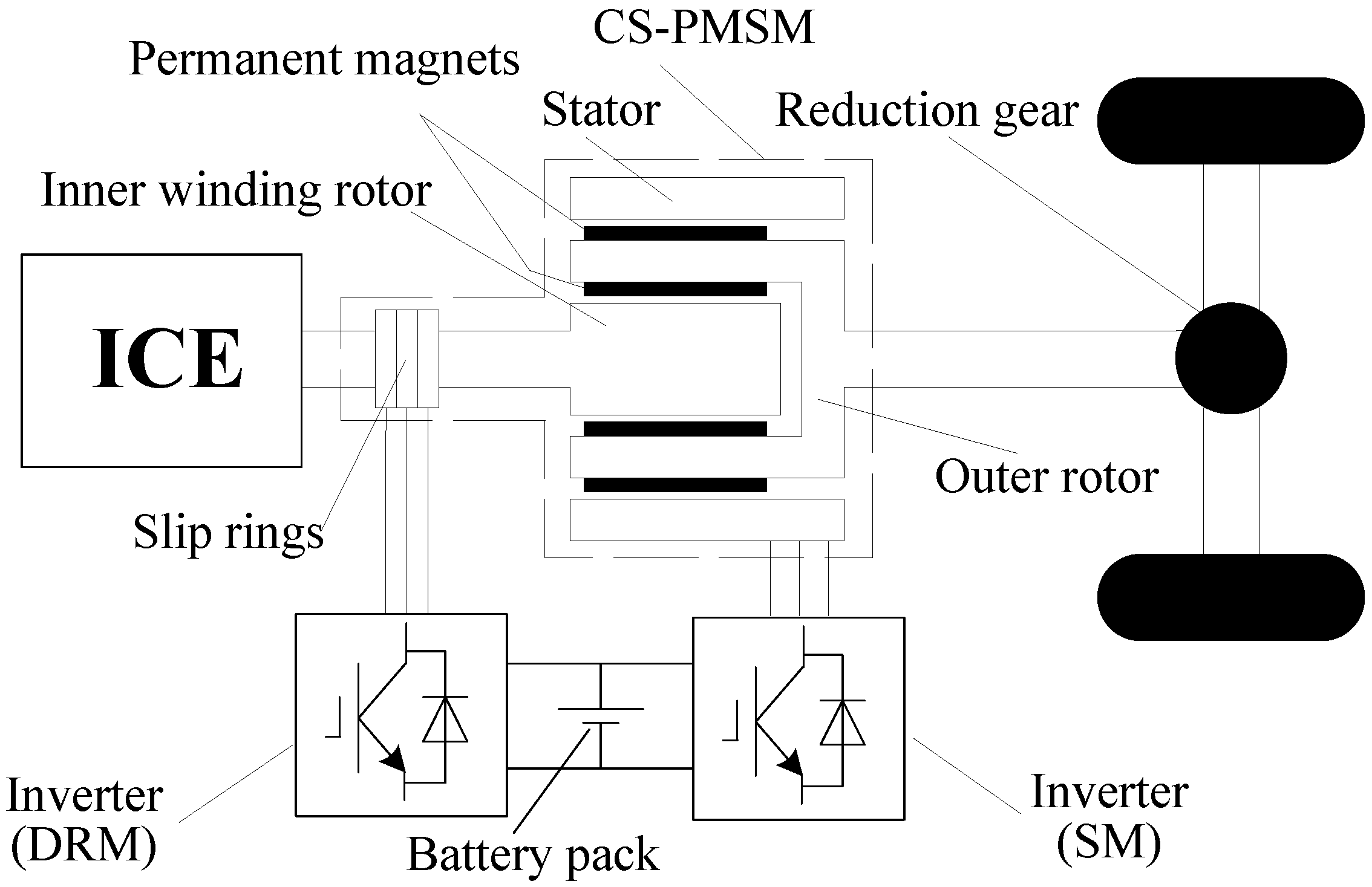
9]. The CS-PMSM hybrid electric system consists of an internal combustion engine (ICE), a battery pack, two inverters, a CS-PMSM, and a reduction gear, as shown in
Figure 1. The radial-radial flux CS-PMSM, inserted between the ICE and the reduction gear, comprises three parts: an inner rotor with three-phase windings (fed via slip rings), an outer rotor with permanent magnets on both sides, and a stator with three-phase windings. The inner winding rotor and outer rotor with inner permanent magnets operate as one machine called double-rotor machine (DRM), and the stator and outer rotor with outer permanent magnets operate as another machine called stator machine (SM). The DRM transfers the ICE torque to the load and enables speed decoupling, and the SM provides the torque difference from the ICE to the load, so the ICE can operate within optimum efficiency region independent of road conditions.
Figure 1.
Hybrid electric system based on CS-PMSM.
Figure 1.
Hybrid electric system based on CS-PMSM.
The CS-PMSM has different topologies according to the path direction of magnetic flux and structural arrangement, and this paper focuses on the radial-radial flux CS-PMSM [
10]. Due to the common magnetic path in the outer rotor, magnetic coupling may exist between the DRM and SM. The magnetic coupling that causes mutual magnetic-field interference, may further lead to unexpected operation, or complex control [
11,
12,
13]. Consequently the design principle to realize magnetic decoupling is analyzed, and the design method to ensure magnetic decoupling with minimum yoke thickness of the outer rotor for improving power density is further investigated in the following sections. A 20 kW prototype machine is designed according to the proposed method, and the magnetic-interference is evaluated through experimental tests. Based on the magnetic decoupling, the CS-PMSM system is finally validated by a driving cycle.
2. Magnetic Decoupling Design of the Radial-Radial Flux CS-PMSM
Magnetic decoupling means the isolation between the DRM flux and the SM working air gap, and vice versa. The outer rotor is the common magnetic path of DRM and SM, with much larger permeability than air. Hence, as long as the outer rotor is unsaturated, the magnetic-field interference can be avoided. Therefore, the design principle for magnetic decoupling is to ensure unsaturated outer rotor.
To avoid magnetic saturation, the yoke of the outer rotor could simply be designed with enough thickness. However, the overuse of steel is unfavorable for improving structural compactness and power density, so the realization of magnetic decoupling with optimal yoke thickness of the outer rotor is investigated in the following four aspects: the magnetization direction of the inside and outside permanent magnets on the outer rotor; the pole-number match of the inside and outside permanent magnets on the outer rotor; the effect of armature reaction on the outer-rotor thickness and evaluation of magnetic decoupling by finite element method (FEM).
2.1. Magnetization Direction of the Inside and Outside Permanent Magnets
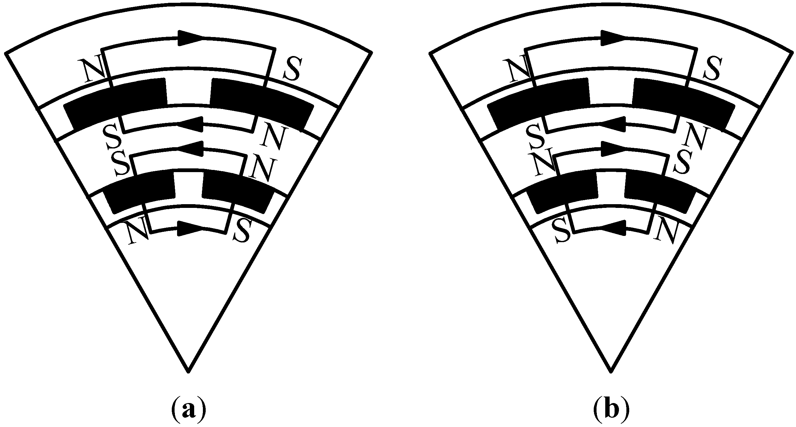
Different from conventional electric machines, the outer rotor of the radial-radial flux CS-PMSM has permanent magnets on both inside and outside. The magnetization direction of the inside and outside permanent magnets can be either opposite or consistent, as shown in
Figure 2.
Figure 2.
Schematic diagram of magnetic flux path when the inside and outside permanent magnets have opposite or consistent magnetization direction. (a) Opposite magnetization direction. (b) Consistent magnetization direction.
Figure 2.
Schematic diagram of magnetic flux path when the inside and outside permanent magnets have opposite or consistent magnetization direction. (a) Opposite magnetization direction. (b) Consistent magnetization direction.
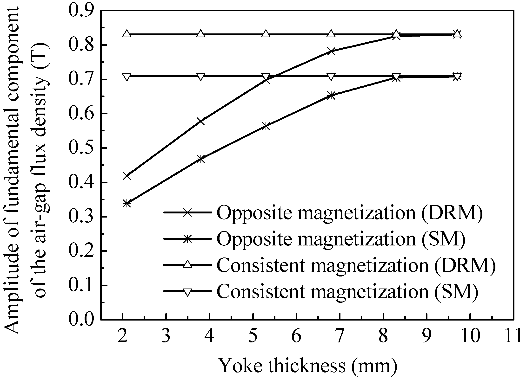
In the case of opposite magnetization direction, the DRM and SM fluxes in the outer rotor are in consistent direction and reinforced, which requires a thicker outer rotor to avoid saturation. In the case of consistent magnetization direction, the DRM and SM fluxes in the outer rotor are in opposite direction and counteracting, which lowers the requirement of outer-rotor yoke thickness. For both cases, the thickness influence of the outer-rotor yoke on the DRM and SM magnetic flux densities is calculated with FEM, as shown in
Figure 3.
It is observed that for opposite magnetization direction, the thickness of the outer-rotor yoke should be 8.5 mm or more to guarantee unsaturated outer rotor and further unreduced magnetic performance. For consistent magnetization direction, the thickness requirement of the outer-rotor yoke is 2 mm, which is even less than that of a comparative conventional machine. Therefore, consistent magnetization direction is preferred to minimize the yoke thickness of the outer rotor.
Figure 3.
Amplitude of fundamental component of the DRM and SM air-gap flux density versus the thickness of the outer-rotor yoke.
Figure 3.
Amplitude of fundamental component of the DRM and SM air-gap flux density versus the thickness of the outer-rotor yoke.
2.2. Pole-Number Match of the Inside and Outside Permanent Magnets
Besides magnetization direction, another issue should be considered: the inside and outside permanent magnets can be designed with different pole numbers and placed at different circumferential positions.
Suppose the inside and outside permanent magnets can be designed with any pole arc coefficient. The opposite magnetization direction of the inside and outside permanent magnets can not be avoided, unless permanent magnets of the two layers apply the same pole number and the same angular positions (i.e., inside and outside permanent magnets are radially opposed).
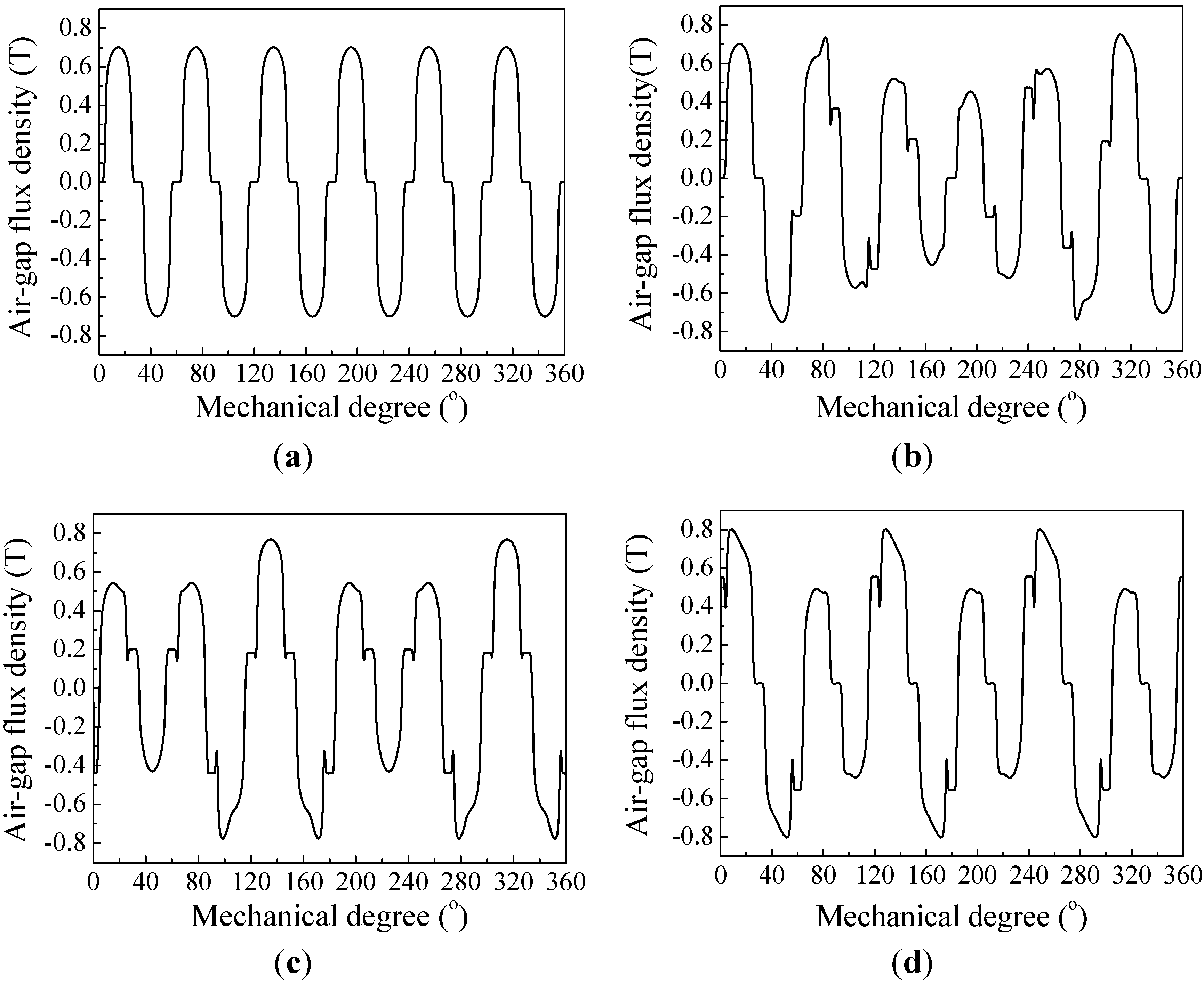
To draw a convincing conclusion, the air-gap flux density of SM is calculated for different pole-pair matches by FEM. The thickness of the outer-rotor yoke is assumed to be 4 mm, and the inner rotor and stator are simplified to be circular ring to get rid of the slot effect on the air-gap flux density waveform. The inside permanent magnets employ 6, 8, 10, 12 poles, respectively, and the outside permanent magnets keep 12 poles. At least two pairs of the inside and outside permanent magnets are placed directly opposite to each other. Waveforms of the SM air-gap flux density are shown in
Figure 4.
We can see that when different pole numbers are employed, due to the inadequate thickness of outer-rotor yoke to avoid saturation, the SM air-gap flux density waveform is badly influenced by the DRM magnetic-field interference. In other words, the same pole number of the inside and outside permanent magnets can decrease the thickness requirement of the outer-rotor yoke.
Figure 4.
Waveforms of the SM air-gap flux density when the DRM and SM have different matches of poles. (a) DRM: 12 poles, SM: 12 poles; (b) DRM: 10 poles, SM: 12 poles; (c) DRM: 8 poles, SM: 12 poles; (d) DRM: 6 poles, SM: 12 poles.
Figure 4.
Waveforms of the SM air-gap flux density when the DRM and SM have different matches of poles. (a) DRM: 12 poles, SM: 12 poles; (b) DRM: 10 poles, SM: 12 poles; (c) DRM: 8 poles, SM: 12 poles; (d) DRM: 6 poles, SM: 12 poles.
2.3. Effect of Armature Reaction
When the machine operates with load, the armature reaction influences not only the main magnetic field, but also the magnetic field distribution in the outer rotor, which may lead to saturation in the outer-rotor.
The CS-PMSM is a high integration of two machines, with two windings,
i.e., the inner-rotor winding and stator winding. The DRM and SM can work independently or operate together, and according to different operating conditions and control strategies, the inner-rotor and stator windings have different matches of armature-reaction mode, as shown in
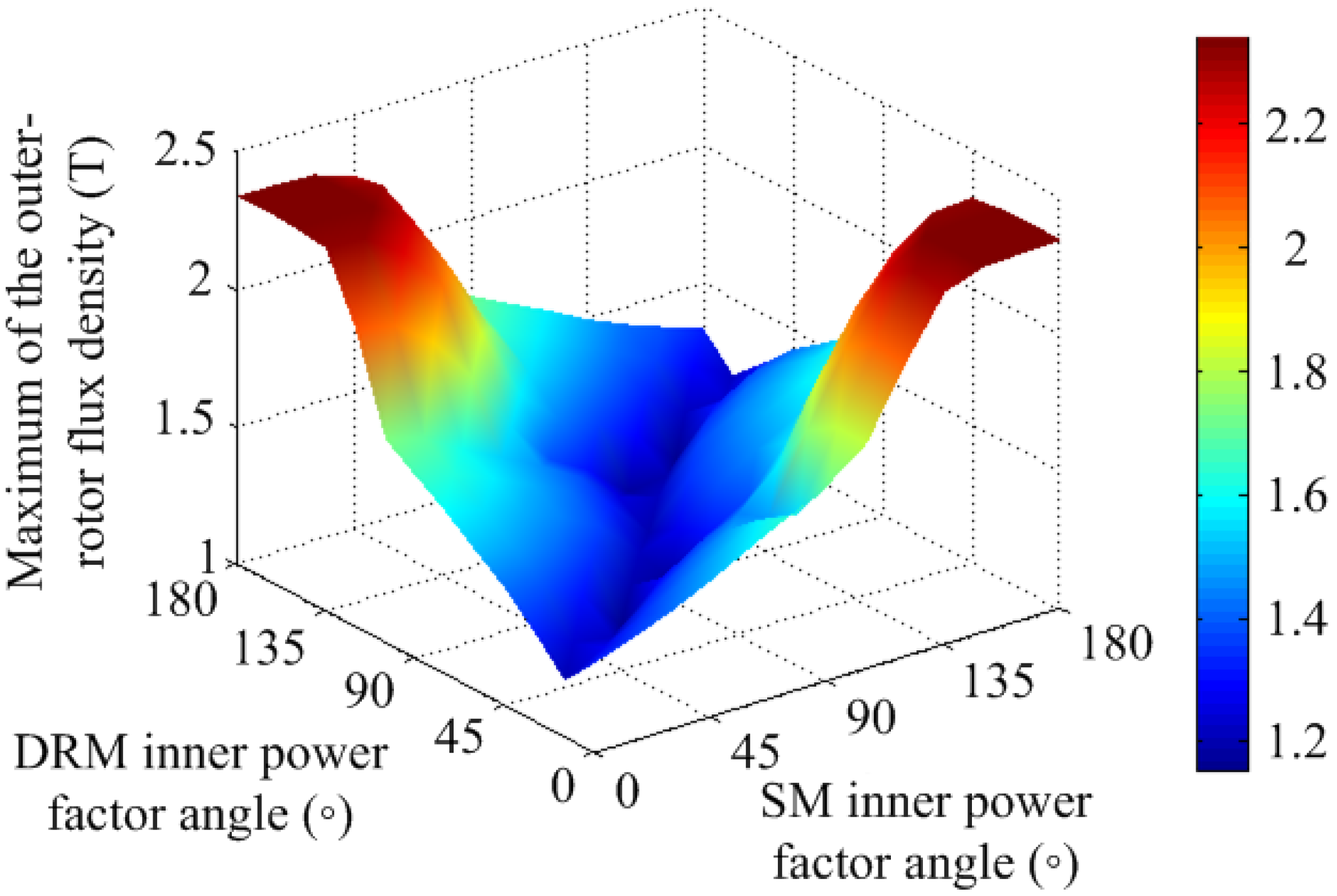
Table 1. The flux density maximum of the outer-rotor yoke is calculated with FEM for all the listed armature-reaction mode matches, as shown in
Figure 5.
In
Figure 5, the flux density peaks occur when the DRM inner power-factor angle is 15° and the SM inner power-factor angle is 180°, and when the DRM inner power-factor angle is 165°, and the SM inner power-factor angle is 0°. This indicates that the flux density peaks occur when the armature reaction magnetic motive forces (MMFs) of the two machines are opposite, and one operates with q-axis armature reaction while the other operates with co-existed q-axis and d-axis demagnetization armature reaction. This conclusion converts the calculation of the armature reaction effect on the outer rotor magnetic field from three-dimension into two-dimension, thus dramatically simplifies the machine design.
Table 1.
Different matches of inner-rotor wingding and stator winding armature-reaction mode.
Table 1.
Different matches of inner-rotor wingding and stator winding armature-reaction mode.
| Match Number | Armature-Reaction Mode of Inner-Rotor Winding | Armature-Reaction Mode of Stator Winding |
|---|
| 1 | none | q-axis armature reaction |
| 2 | q-axis armature reaction | none |
| 3 | q-axis armature reaction | q-axis armature reaction (opposite to that of inner-rotor winding) |
| 4 | q-axis armature reaction | q-axis armature reaction (consistent to that of inner-rotor winding) |
| 5 | none | co-existed q-axis and d-axis demagnetization armature reaction |
| 6 | co-existed q-axis and d-axis demagnetization armature reaction | none |
| 7 | q-axis armature reaction | co-existed q-axis and d-axis demagnetization armature reaction |
| 8 | co-existed q-axis and d-axis demagnetization armature reaction | q-axis armature reacton |
| 9 | co-existed q-axis and d-axis demagnetization armature reaction | co-existed q-axis and d-axis demagnetization armature reaction |
Figure 5.
Maximum of the outer-rotor flux density versus the DRM and SM inner power-factor angles.
Figure 5.
Maximum of the outer-rotor flux density versus the DRM and SM inner power-factor angles.
Based on the above analysis and calculations, the design method can be summarized as follows: (1) the inside and outside permanent magnets should employ consistent magnetization direction; (2) the inside and outside permanent magnets should employ the same pole number and opposed configuration; (3) the armature reaction effect should be considered according to different operating conditions and control strategies.
2.4. Evaluation of Magnetic Decoupling by FEM
A 20 kW prototype machine was designed with the proposed design method. The power ratings of the DRM and SM are both 10 kW, the rated currents are 30 A, and the rated speeds are 3,000 r.p.m. When the two machines operate simultaneously, the mutual effects on torque output are calculated with FEM under both no-load (considering the effect of permanent magnets) and load (considering the effect of armature reaction) condition, as shown in
Table 2.
Table 2.
Comparison of electromagnetic torque.
Table 2.
Comparison of electromagnetic torque.
| DRM Operating Condition | SM Electromagnetic Torque (Nm) | SM Operating Condition | DRM Electromagnetic Torque (Nm) |
|---|
| no load at 3000 r.p.m. | 39.28 | no load at 3000 r.p.m. | 41.74 |
| load current 30 A as motor | 39.18 | load current 30 A as motor | 41.74 |
| load current 30 A as generator | 39.40 | load current 30 A as generator | 41.74 |
From
Table 2, we can see that the DRM no-load and load operations have little influence on the SM electromagnetic torque, and vice versa, which indicates the magnetic decoupling of DRM and SM.
2.5. Mechanical Motion Equations of the CS-PMSM System
Based on the magnetic decoupling, the DRM and SM can be treated as two conventional machines whose speed equations are shown by Equations (1) and (2):
where
,
,
,
, are the mechanical speeds of SM, outer rotor, DRM and inner rotor.
Without considering mechanical losses, when the outer rotor and inner rotors are respectively connected with the load and the ICE, as shown in
Figure 1, speed and torque equations of the CS-PMSM system can be expressed by Equations (3)–(5):
where
and
are the mechanical speeds of the load and ICE,
and
are the torque delivered to final load and the input torque from ICE,
and
are the electromagnetic torques of DRM and SM,
and
are the outer-rotor and inner-rotor moments of inertia.
By the torque control of DRM, the ICE can operate at an efficient speed independent of the load speed. As the electromagnetic torque of DRM is delivered to the load directly, the torque of SM is controlled to satisfy overall driving demand. Hence, the operation of ICE can be fully regulated to realize optimum fuel efficiency by CS-PMSM.
3. Experimental Validation of CS-PMSM
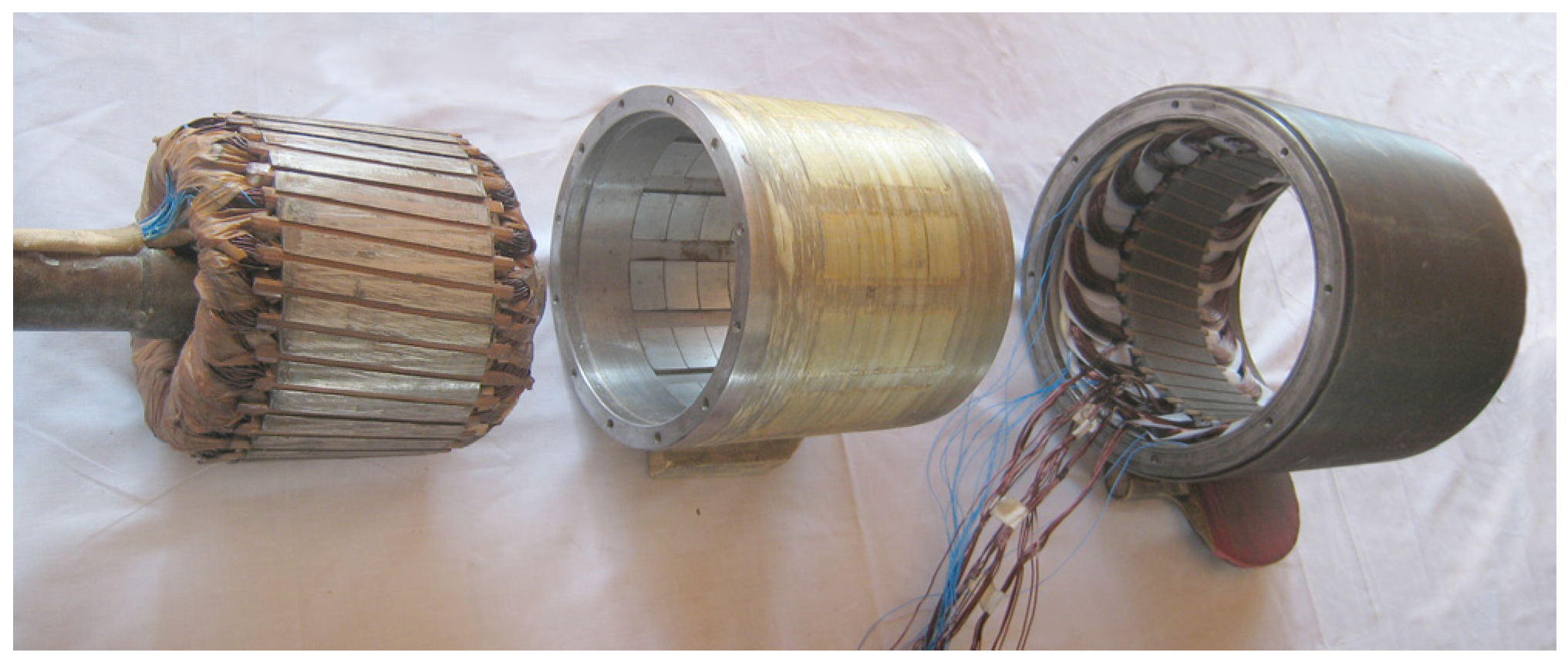
A prototype machine was manufactured, as shown in
Figure 6. A test bench was built and experiments were conducted to evaluate the magnetic decoupling and independent control. To validate various functions of CS-PMSM, a driving cycle was designed and carried out on the same bench.
Figure 6.
Main components of the manufactured CS-PMSM prototype machine: the inner rotor (left), the outer rotor with permanent magnets on both sides (middle), and the stator with housing (right).
Figure 6.
Main components of the manufactured CS-PMSM prototype machine: the inner rotor (left), the outer rotor with permanent magnets on both sides (middle), and the stator with housing (right).
3.1. CS-PMSM Test Bench
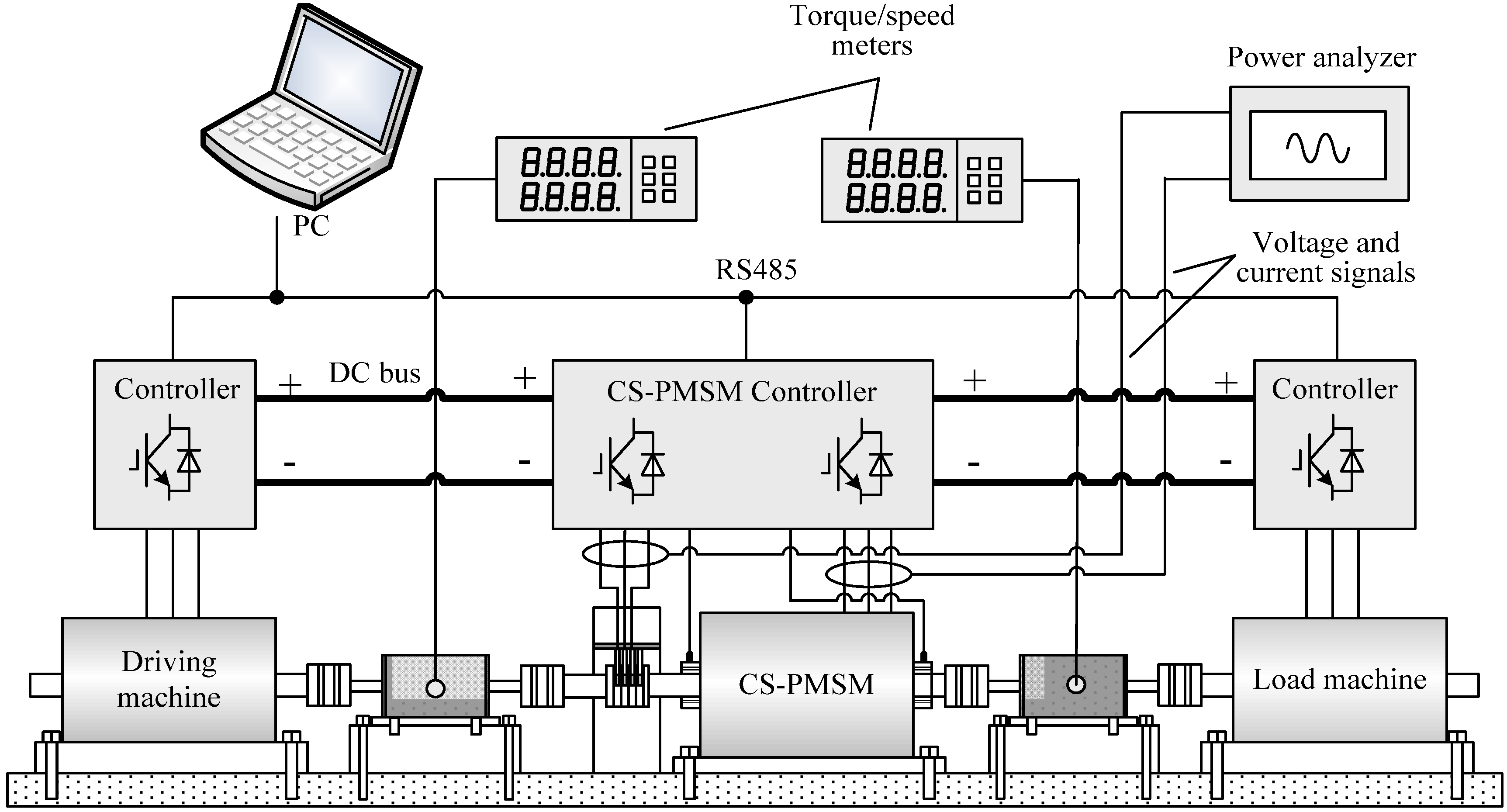
A test bench was built as shown in
Figure 7. An electric machine is connected to the inner rotor of CS-PMSM to simulate the ICE driving and another is connected to the outer rotor to operate as load.
Figure 7.
CS-PMSM test bench.
Figure 7.
CS-PMSM test bench.
The controllers are connected to the same DC bus, so no excessive energy is produced by regenerative breaking under steady operation. Power analyzer and speed/torque meters are used for electric and mechanical measurement of the CS-PMSM. During the experiment, the required torque and speed values of the ICE, final gear and CS-PMSM are sent to corresponding controllers. Speed control is implemented for both driving and load machines, while torque control is used for DRM and SM. The torque control algorithms of DRM and SM controllers are id = 0, so the q-axis current is proportional to torque reference. Owing to the magnetic decoupling, the CS-PMSM torque controller can be implemented as two conventional 3-phase controllers. However, it should be noted that the position feedback for DRM should be the differential position of its dual rotors.
3.2. Experimental Evaluation of Magnetic Decoupling
The magnetic-coupling degree is further directly evaluated by comparing air-gap flux density. Generally, it is difficult to precisely measure the value and waveform of the air-gap density during the operation of electric machines. The input voltage is linearly related to the air-gap flux density when the electric machine operates at constant speed and load and the influences of its temperature change and winding resistance are not considered. Thus, the comparison of flux density can be converted to the comparison of the input voltage. By changing the operating condition of one machine while controlling the other to work at 1000 r.p.m. with full load, the RMS input voltages of SM and DRM are compared respectively, as shown in
Table 3.
Table 3.
Comparison of input voltages.
Table 3.
Comparison of input voltages.
| DRM Operating Condition | SM Voltage (V) | SM Operating Condition | DRM Voltage (V) |
|---|
| no load | 71.55 | no load | 72.91 |
| load current 30 A as motor | 71.61 | load current 30A as motor | 72.99 |
| load current 30 A as generator | 71.57 | load current 30A as generator | 72.91 |
In
Table 3, it is obvious that the input voltage of one machine is scarcely affected by the operation of the other machine, indicating that the mutual magnetic interference between SM and DRM dose not exist (the little change of the load voltage might be caused by the slight change of machine temperature) or is slight enough to be negligible. Thus, the magnetic decoupling and independent control of the two electric machines are feasible.
3.3. Function Validation of CS-PMSM
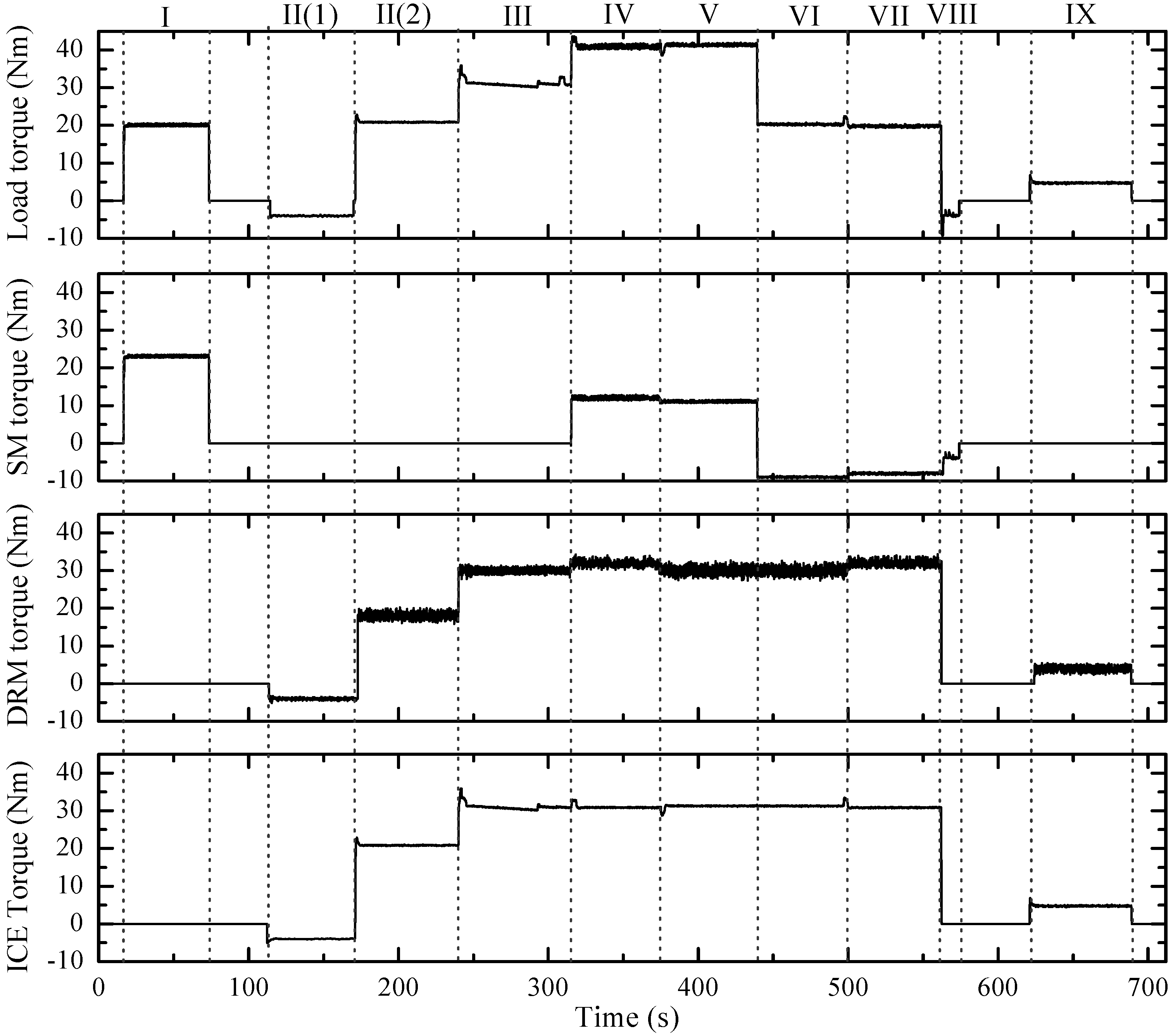
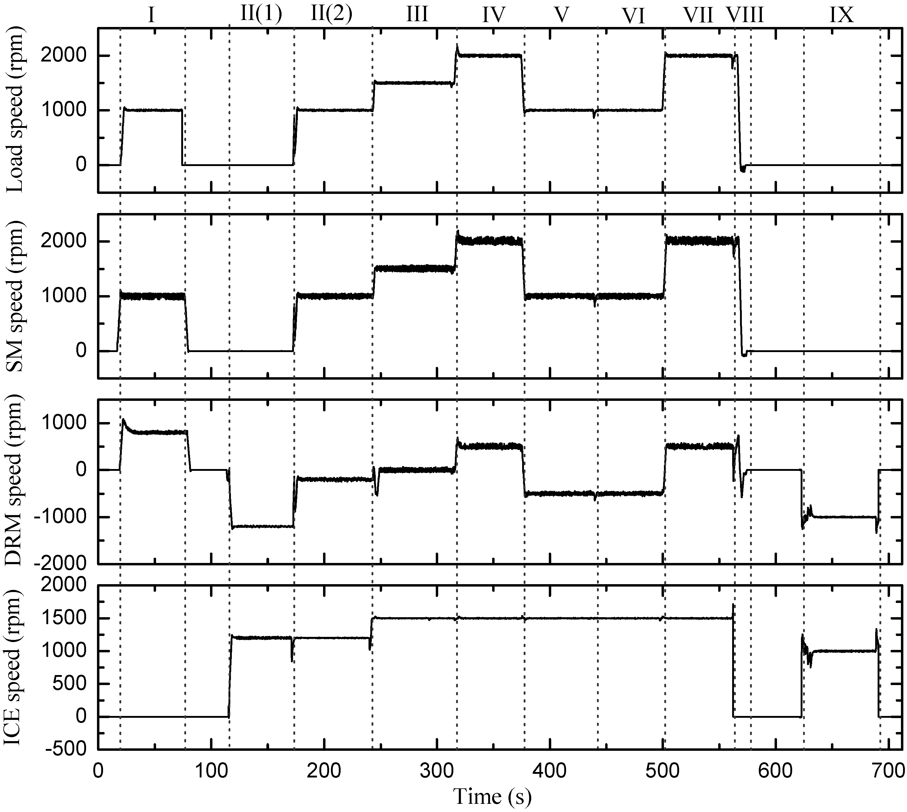
The CS-PMSM not only has the functions of adjusting the speed and torque from the ICE to the load, helping the ICE operate within optimum efficiency region, but also can act as starter and allow regenerative breaking. The process of a hybrid electric vehicle from starting to stop containing the various functions of CS-PMSM is designed and carried out on the test bench. The tested torque and speed curves are shown in
Figure 8 and
Figure 9, respectively. The whole process is divided into nine intervals described as follows.
Interval I: Only SM provides the demanded torque to drive the vehicle from 0 to 1000 r.p.m. This operating mode applies to low driving power demand under high battery SOC. For instance, when starting or running at light load, the vehicle is simply driven by battery to prevent the ICE from inefficient low-speed and low-torque operating region.
Interval II: If the battery SOC is low when the vehicle starts, the ICE is driven to the required speed for ignition firstly by the DRM which works as starter, as shown in
Figure 8 and
Figure 9 II(1). Then the ICE operates and provides power that is splitted to drive the vehicle and recharge the battery, and the DRM switches to generating operation, as shown in
Figure 8 and
Figure 9 II(2).
Interval III: After the ICE runs into its optimum efficiency region, the DRM can operate in the electromagnetic clutch condition at zero speed and only transfers the ICE torque.
Here we suppose the optimum working point of ICE is 30 Nm at 1500 r.p.m. In the next four intervals, we will validate the speed and torque adjustment function of the DRM and SM for assisting the ICE with efficient operation.
- 4.
Interval IV: As shown in
Figure 8 and
Figure 9, both SM and DRM operate as motor to increase the torque and speed from the ICE output to the load. This operating mode can provide a better accelerating performance at high speeds by employing both ICE and battery power.
- 5.
Interval V: In this operating mode, the SM operates as motor to increase the torque while the DRM operates as generator with negative speed. This case is used when the vehicle is running with low speed and heavy load, or meets with uphill path, the vehicle can ensure a full acceleration to provide a smooth and powerful response. This mode realizes the low-gear function of a gearbox.
- 6.
Interval VI: If the battery SOC is low and the battery needs immediate charging, both machines can operate as generator. In this case, the ICE is working with a higher speed and torque than load requirement.
- 7.
Interval VII: In this case, the SM operates as generator to decrease the torque and the DRM operates as motor due to the increased speed. The situation may happen when the vehicle meets with the downhill path. This operating mode realizes the high-gear function of a gearbox.
- 8.
Interval VIII: This interval shows the decelerating and breaking of the vehicle. In this case, the ICE and DRM are shut down, and then the SM provides breaking torque to reduce the vehicle speed and acts as a generator to recharge the battery. As a permanent-magnet machine acts as the vehicle load on the test bench, the decelerating time is very short and the breaking torque of SM should be limited to prevent the load machine from reverse speeding up.
- 9.
Interval IX: When the vehicle stops with low battery SOC, the ICE keeps running to charge the battery by operating the DRM as a generator. Therefore, the hybrid electric vehicle can maintain enough battery energy for the next start without being plugged in for recharging.
As the prototype machine is downsized, and two electric machines act as the ICE and the load, which have much faster response than the actual vehicle, the torque and speed curves in
Figure 8 and
Figure 9 are not quite consistent with the actual situation and the acceleration and deceleration times are both quite short. However, the operating modes of the CS-PMSM are the same as in practical applications. The functions of the CS-PMSM acting as starter, regenerative breaking, and helping the ICE operate at optimum efficiency point are validated.
Figure 8.
The tested torque curves of the ICE, DRM, SM and load machine.
Figure 8.
The tested torque curves of the ICE, DRM, SM and load machine.
Figure 9.
The tested speed curves of the ICE, DRM, SM and load machine.
Figure 9.
The tested speed curves of the ICE, DRM, SM and load machine.
4. Conclusions
The essential way to realize magnetic decoupling is to keep the outer rotor of the CS-PMSM unsaturated considering both the influences of the PMs and armature reaction. The two-layer PMs should employ consistent magnetization direction, the same pole number and opposed configuration, so that the fluxes from the DRM and SM are counteracting in the common flux path, and the resultant flux can remain low, which reduces the requirement of outer-rotor thickness. The proposed methods are supported by further FEM evaluation of magnetic coupling between the DRM and SM. Based on the magnetic decoupling, mechanical motion equations of the CS-PMSM system is deduced, showing that the CS-PMSM can realize sufficient speed and torque control of the ICE while satisfying driving demand. A prototype machine is manufactured according to the proposed methods. Experiments showed that little magnetic coupling exist between the two machines. By a designed drive cycle, the CS-PMSM system is proven to realize all the operating states of a typical hybrid electric vehicle.
Acknowledgments
This work was supported in part by National Natural Science Foundation of China under Project 50877013 and 51077026, in part by the 863 Plan of China under Project 2011AA11A261, and in part by the Fundamental Research Funds for the Central Universities (Grant No. HIT.BRET1.2010013).
References
- Eriksson, S.; Sadarangani, C. A four-quadrant HEV drive system. In Proceedings of IEEE 56th Vehicular Technology Conference, Vancouver, Canada, 24–28 September 2002; Volume 3, pp. 1510–1514.
- Magnussen, F.; Sadarangani, C. Electromagnetic transducer for hybrid electric vehicles. In Proceedings of Nordic Workshop on Power and Industrial Electronics, Stockholm, Sweden, 12–14 August 2002; pp. 5–6.
- Magnussen, F.; Thelin, P.; Sadarangani, C. Design of compact permanent magnet machines for a novel HEV propulsion system. In Proceedings of the 20th International Electric Vehicle Symposium and Exposition (EVS), Long Beach, CA, USA, 15–19 November 2003; pp. 1–12.
- Nordlund, E.; Eriksson, S. Test and verification of a four-quadrant transducer for HEV applications. In Proceedings of IEEE Vehicle Power and Propulsion Conference, Chicago, IL, USA, 2–5 September 2005; pp. 37–41.
- Xu, L.Y. A new breed of electrical machines-basic analysis and applications of dual mechanical port electric machines. In Proceedings of the 8th International Conference on Electric Machines and Systems, Nanjing, China, 27–29 September 2005; Volume 1, pp. 24–31.
- Chau, K.T.; Chan, C.C. Emerging energy-efficient technologies for hybrid electric vehicles. Proc. IEEE 2007, 95, 821–835. [Google Scholar] [CrossRef]
- Chau, K.T.; Chan, C.C.; Liu, C. Overview of permanent-magnet brushless drives for electric and hybrid electric vehicles. IEEE Trans. Ind. Electron. 2008, 55, 2246–2257. [Google Scholar] [CrossRef] [Green Version]
- Cheng, Y.; Cui, S.M.; Song, L.W.; Chan, C.C. The study of the operation modes and control strategies of an advanced electromechanical converter for automobiles. IEEE Trans. Magn. 2007, 43, 430–433. [Google Scholar] [CrossRef]
- Zheng, P.; Liu, R.R.; Thelin, P.; Nordlund, E.; Sadarangani, C. Research on the parameters and performances of a 4QT prototype machine used for HEV. IEEE Trans. Magn. 2007, 43, 443–446. [Google Scholar] [CrossRef]
- Zheng, P.; Liu, R.R.; Wu, Q.; Tong, C.D.; Tang, Z.J. Compound-structure permanent-magnet synchronous machine used for HEVs. In Proceedings of International Conference on Electric Machines and Systems (ICEMS2008), Wuhan, China, 17–20 October 2008; pp. 2916–2920.
- Cui, S.M.; Huang, W.X.; Cheng, Y.; Ning, K.W.; Chan, C.C. Design and experimental research on induction machine based electrical variable transmission. In Proceedings of IEEE Vehicle Power and Propulsion Conference, Arlington, TX, USA, 9–12 September 2007; pp. 231–235.
- Guo, X.Z.; Fan, T.; Wen, X.H.; Zhao, F. Electromagnetic coupling analysis of uniform magnetic-filed permanent magnet dual mechanical port machine. In Proceedings of International Conference on Electric Machines and Systems, Wuhan, China, 17–20 October 2008; pp. 3181–3184.
- Zhao, F.; Wen, X.H.; Guo, X.Z.; Han, L.; Guo, X.H. Study of field coupling in dual mechanical port electrical machines. In Proceedings of International Conference on Electrical Machines and Systems, Seoul, Korea, 8–11 October 2007; pp. 1591–1595.
© 2012 by the authors; licensee MDPI, Basel, Switzerland. This article is an open access article distributed under the terms and conditions of the Creative Commons Attribution license (http://creativecommons.org/licenses/by/3.0/).


