Article

Building Space Heating with a Solar-Assisted Heat Pump Using Roof-Integrated Solar Collectors

1
School of Chemical Engineering and Technology, Tianjin University, 300072, Tianjin, China
2
School of Architecture, Tianjin University, 300072, Tianjin, China
*
Author to whom correspondence should be addressed.
Energies 2011, 4(3), 504-516; https://doi.org/10.3390/en4030504
Submission received: 25 January 2011 / Revised: 2 March 2011 / Accepted: 7 March 2011 / Published: 14 March 2011
(This article belongs to the Special Issue Advances in Solar Energy)

Abstract

:
A solar assisted heat pump (SAHP) system was designed by using a roof-integrated solar collector as the evaporator, and then it was demonstrated to provide space heating for a villa in Tianjin, China. A building energy simulation tool was used to predict the space heating load and a three dimensional theoretical model was established to analyze the heat collection performance of the solar roof collector. A floor radiant heating unit was used to decrease the energy demand. The measurement results during the winter test period show that the system can provide a comfortable living space in winter, when the room temperature averaged 18.9 °C. The average COP of the heat pump system is 2.97 and with a maximum around 4.16.

1. Introduction

Building energy consumption accounts for approximately 25–30% of the total energy usage in China [1], while in some industrialized countries the number can reach 40% [2]. Of this energy, the percentage used for supplying domestic hot water and running HVAC systems uses the most part. Interest has been growing in the adoption of new methodologies to utilize solar energy effectively. Solar collectors for domestic hot water provision have been widely used, especially in China. Sometimes, a larger area solar collector can supply space heating, but at the same time it also brings up the cost. Furthermore, another issue solar collectors are facing, is how to integrate perfectly with the building envelope. The double-facade is the key reason that causes the problems of high cost and additional building construction load. Finding good ways to fulfill the building integration for city solar systems is quite essential, and recently some investigations have been proceeding towards this. By embedding the tubes directly underneath the roof concrete layer, the roof construction can absorb solar heat by using the concrete layer as the absorber. Thus, building integration of solar collectors can be accomplished by this functionalization usage of conventional construction materials. Several researchers have studied this type of collector and obtained some experimental and theoretical results (Bopshetty [3], Chaurasia [4], Bilgen and Richard [5]). Similar ways have been used by others. Medved [6] designed a large-panel unglazed roof-integrated liquid solar collector based on standard metal roofing. In 2004, Abbott presented a legend precast solar collector used for space heating and domestic hot water [7].
The most efficient way to reduce the collector heat loss is to lower the demand temperature to decrease the temperature difference between the solar collector panel and the ambient temperature. Using the collector as the heat pump heat source makes achieving a high solar heat collection efficiency while at the same time meeting the heat usage requirements feasible. For heat pumps, a basic factor of great importance for their successful application is the availability of a cheap, dependable heat source for the evaporator—preferably one at a relatively high temperature [8]. The coefficient of performance (COP) of a heat pump depends to the great extent on the temperature of the evaporator. Combining the heat pump and solar energy is a mutual beneficial way to increase the heat pump COP and the solar collector efficiency. The solar collector loop is used to boost the heat source temperature of the heat pump, thereby increasing the heat pump’s annual and seasonal performance. Similarly, the heat pump can reduce the collector operating temperature, which allows for sustainable heat gains even under marginal weather conditions and the use of inexpensive, unglazed solar collectors. This combined system could operate more efficiently under a wide range of weather conditions and for more hours each day. Abundant work, both theoretical and experimental, has been done on solar assisted-heat pump systems [9,10,11,12,13,14,15,16,17,18,19,20,21,22,23,24,25]. The results presented show that the thermal efficiency of the collector which acts as the heat source of a heat pump system is high because of the lower temperature difference between the collector and the environment, while the heat pumps’ annual and seasonal performance were increased by increasing the heat source temperature of the heat pumps.
A floor radiation heating system is an efficient way to achieve indoor thermal comfort with low-energy demands. Instead of heating and circulating air throughout the house, radiant heat warms objects—carpet, furniture and even people. The most favorable aspect of radiant floor heating systems is that by virtue of their design they possess significantly better potential for energy storage than hydraulic heating systems with baseboard or convector units [26,27].
In the present paper, a solar assisted heat pump (SAHP) system combining all the above new methodologies is put forward, and the actual performance was tested after it was demonstrated in a villa in Tianjin China.

2. Design Process of the Proposed System

The proposed system mainly consists of the solar roofing collector, which features high solar utilization efficiency and complete roof integration, the radiant heating floor end system, which guarantees the lower energy demand and more comfortable indoor environment, and a compressor and related devices, which couple the source and end part. System design was first done by considering every aspect, including but not limited to the building construction, local climate conditions, local energy saving regulations and component coupling. Optimization of the system is aimed at achieving minimal energy usage, the easiest operation and the least maintenance work.

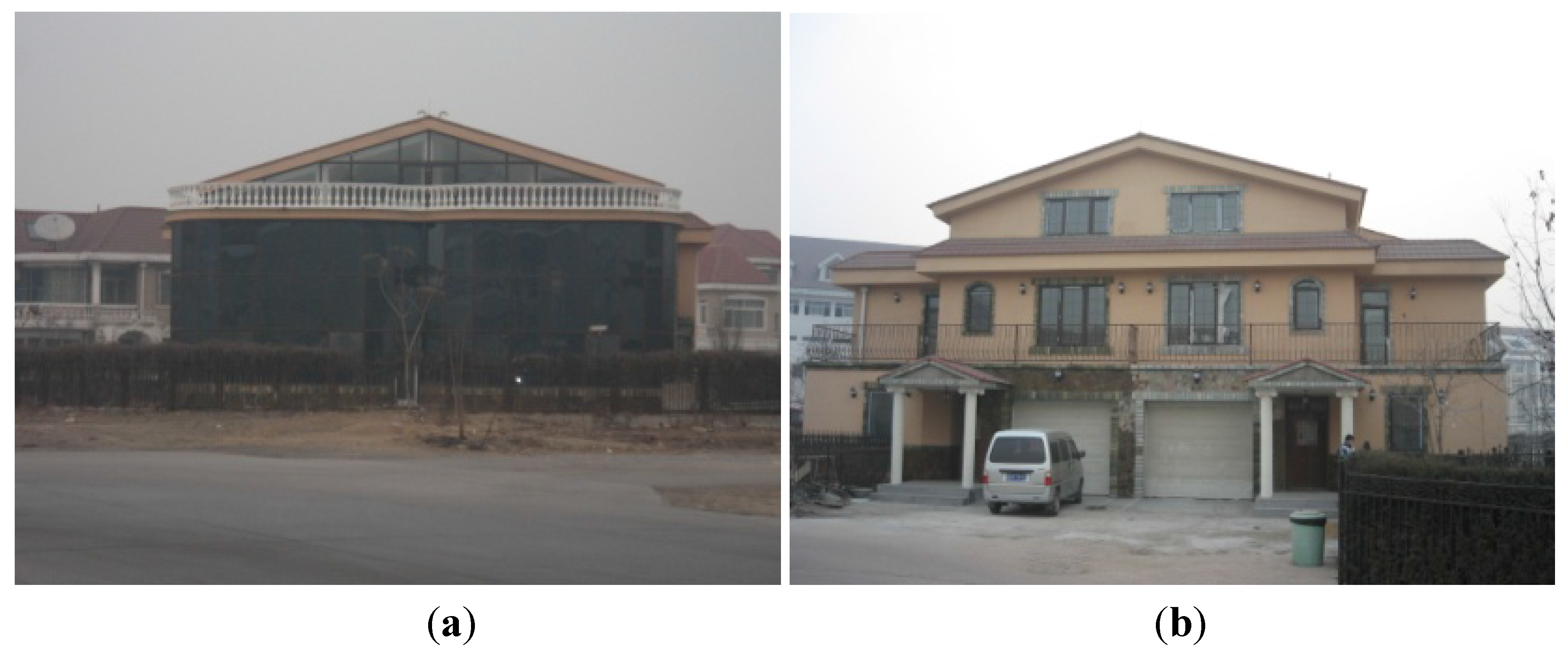
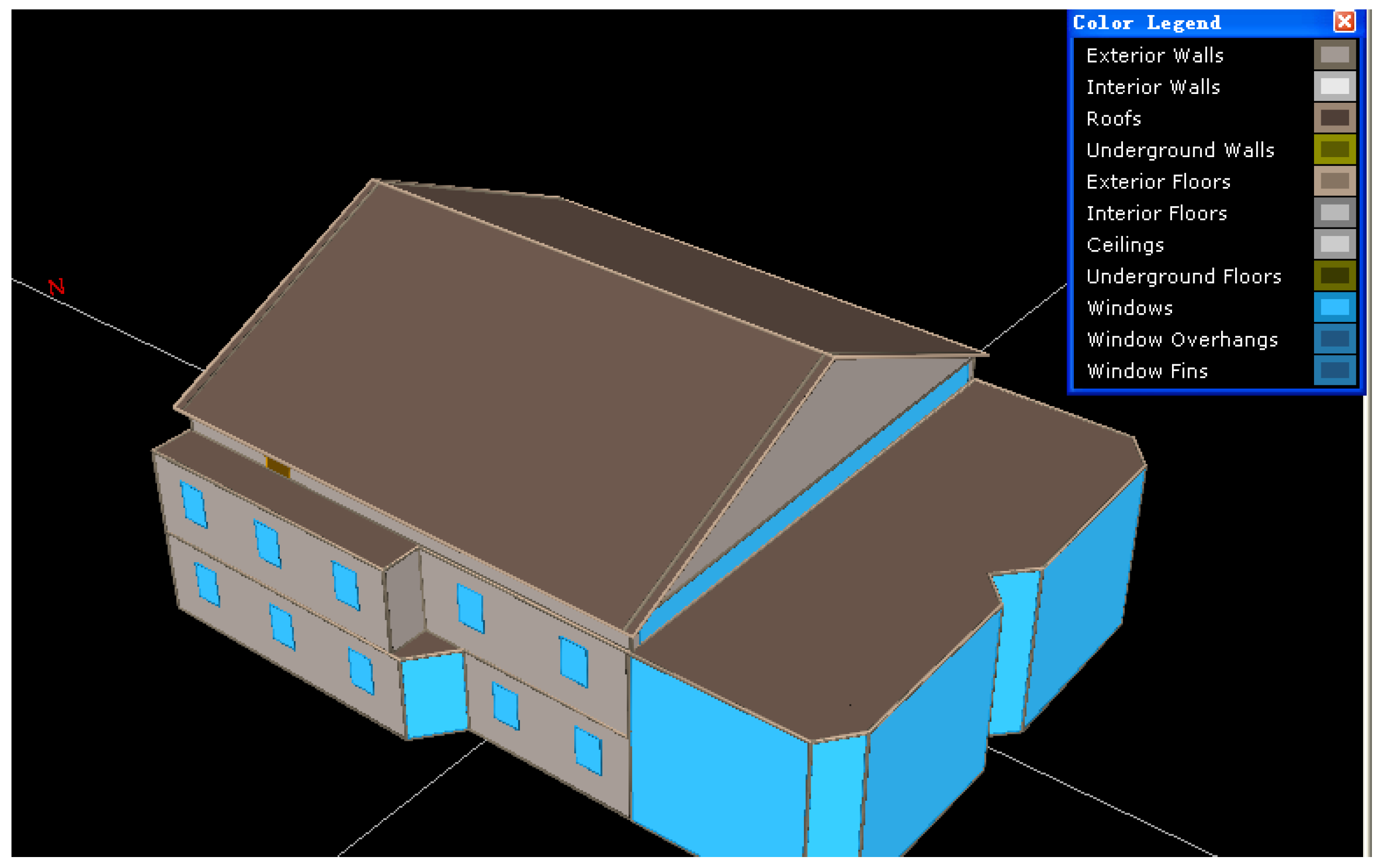
2.1. Building Description

The test building is a three-story villa located in Tianjin city, with an overall floor area of 820 m2. Tianjin (latitude of 39°08' and the longitude of 117°07') lies in the cold climate zone in China. The design temperatures in winter and summer are −9.4 °C and 33.9 °C, respectively, and the corresponding desired indoor temperatures are 18 °C and 26 °C. Conventionally, the space heating period last from November 15 to the following March 15, and the space cooling days are from June 1 to September 15.
Figure 1. Pictures showing the appearance the demonstration building. (a) South view; (b) North view.
Energies 04 00504 g001
The villa was reconstructed for style retrofitting as well as to lower its energy usage. The building roof and wall construction were applied concrete and fired bricks, respectively. High thermal-insulation performance construction materials were utilized during the reconstruction, like the hollow double-glazing windows, expanded polystyrene (EPS) insulation boards (thickness: 80 mm, λ: 0.4 Wm−2∙k−1) on the external walls, heat recovery units, and energy efficient appliances. The retrofitted building is shown in Figure 1.

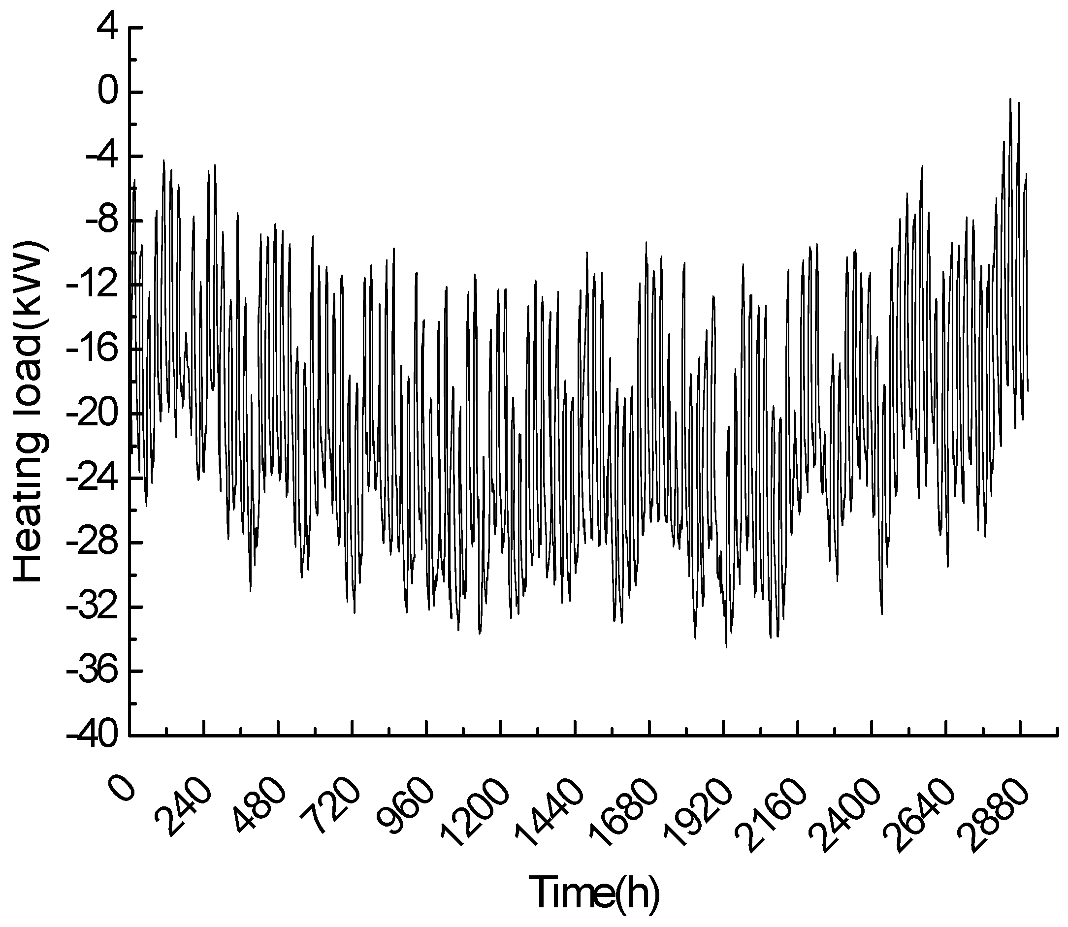
2.2. Space Heating Load Calculation

The heating load provides the basic information for the energy system design. In the present paper, the eQUEST software tool was used to calculate the hourly building energy consumption. The eQUEST program is the latest official version of DOE-2 derived user-interface, which also extends and expands DOE-2’s capabilities in several important ways: eQUEST calculates hour-by-hour building energy consumption over an entire year (8760 hours) using hourly weather data for the location under consideration [28,29,30].
Figure 2. The eQUEST building model.
Energies 04 00504 g002
The geometric model of the building created by eQUEST is shown in Figure 2. Figure 3 gives the calculated hourly heating load obtained by inputting the building construction information, climate conditions, indoor thermostat temperature, system operation mode and related information,. Because the designed building roof was well insulated with the 80 mm EPS board, the influence of the roof-integrated solar collector wasn’t taken into consideration. As seen from Figure 3, the peak heating load of the demonstrated villa in the whole winter is less than 34 kW and fluctuates with the weather conditions.
Figure 3. The heating load of the building during winter time.
Energies 04 00504 g003

2.3. Solar Roofing

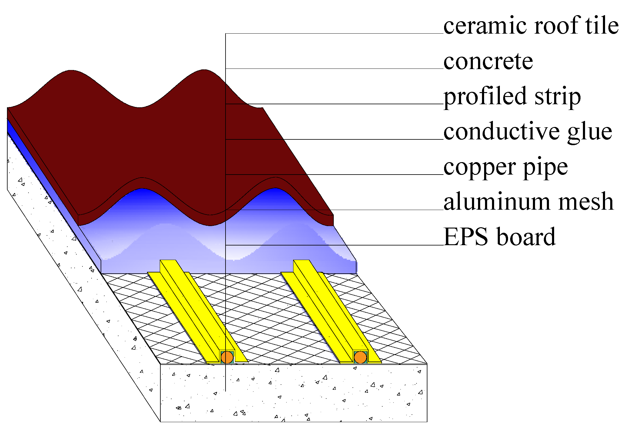
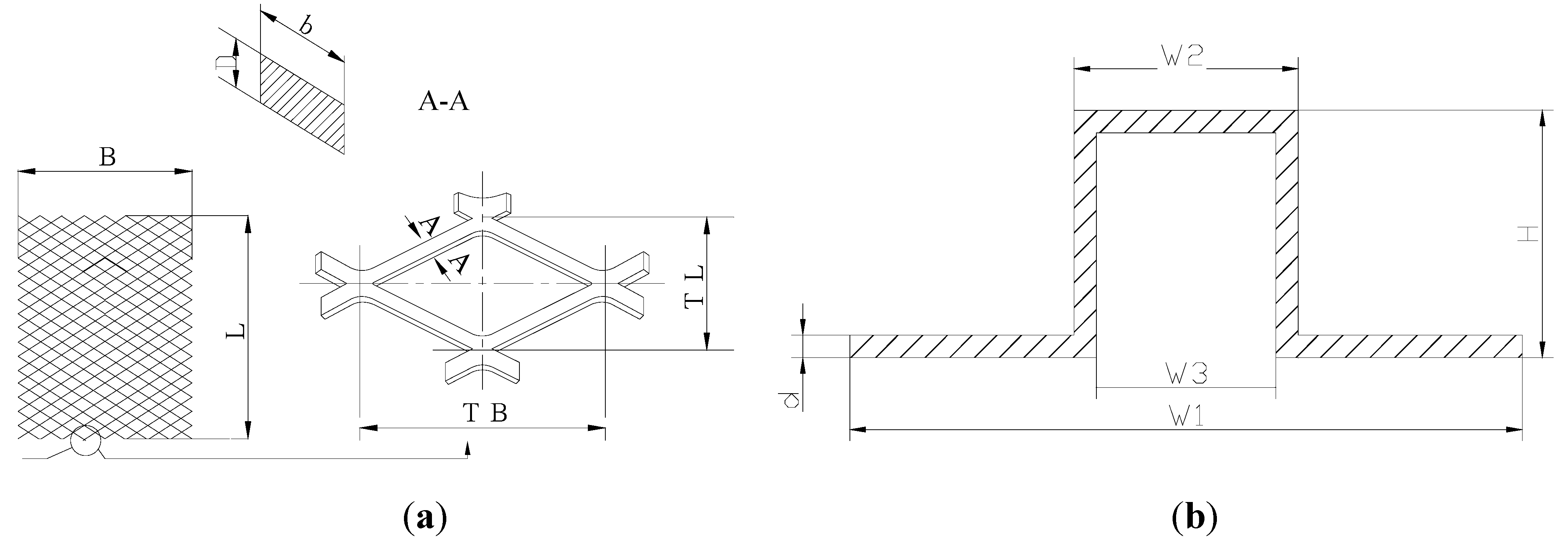
2.3.1. Integration Structure

The east-west aligned roof is sloped at an angle of 25° and finished with ceramic tiles. Heat collecting devices were installed underneath the roof tiles, so from outside the solar collector is invisible and totally integrated into the building envelope as part of the roofing structure. Figure 4 shows the detailed roofing structure. After the EPS board was added to the roof structure, an aluminum mesh layer was laid, then the copper tube was arranged and covered with profiled aluminum strips, afterwards, a concrete layer was paved and finally finished with the ceramic tiles. The space between the pipes is 150 mm. Table 1 lists the size and physical properties of the construction materials used.
Figure 4. The arrangement of the solar collector.
Energies 04 00504 g004
Table 1. The size and physical properties of the construction materials.
ItemFeature Size (mm)λ (W/m K)ρ (kg/m3)Cp (J/kg K)
Copper tube8 × 0.53988954406
Aluminum mesh plate3600 × 1800227.82770921
Profiled strip 227.82770921
Ceramic tile360 × 270 × 100.722300879
Conductive glue 71755545
EPS2000 × 1000 × 800.03530
Concrete paving 0.932400920
The structure of the aluminum mesh plate is shown in Figure 5a, where length L and width B of the mesh plate are 3.6 m and 1.8 m, respectively, thickness D of the mesh plate is 2 mm; the width of the mesh stalk is 4.95 mm, the long pitch TL and short pitch of the mesh are 120 mm and 44 mm, respectively. The structure of the profiled strip is shown in Figure 5b, the total width W1 is 28 mm, the top width W2 is 10 mm, the height is 10 mm, and the depth d is 1 mm.
Figure 5. The structure of the aluminum mesh plate and profiled strip. (a) Aluminum mesh plate; (b) Profiled strip.
Energies 04 00504 g005

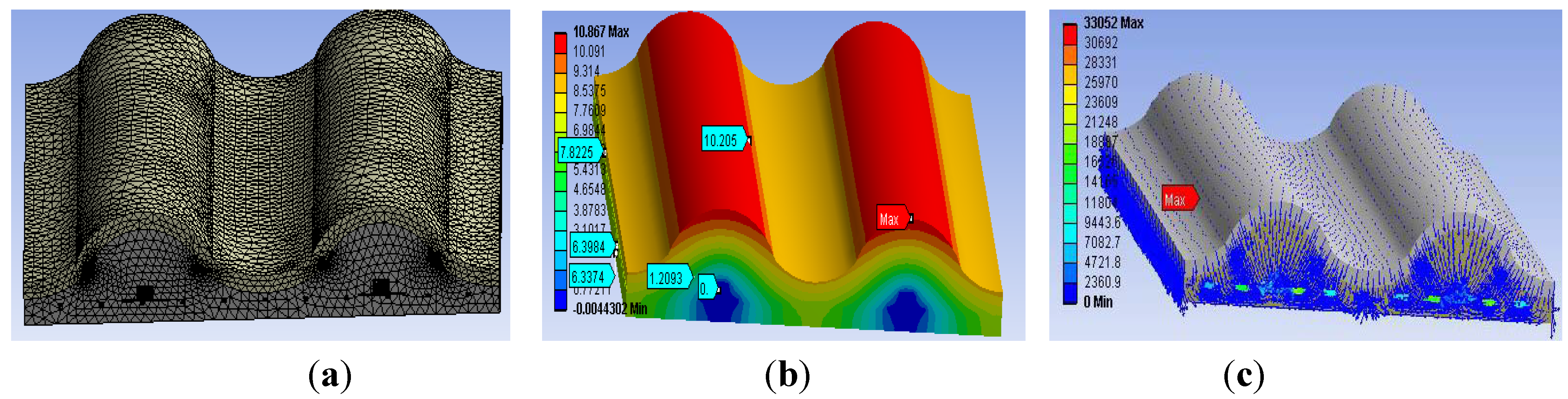
2.3.2. Thermal Performance Evaluation

2.3.2.1. Model Description

A three-dimension numerical heat transfer model was established based on the structure illustrated in Figure 4; the calculation domain was chosen as a solid with a width of 480 mm, a length of 500 mm and the height from the EPS to the rooftop. The following assumption was made to simplify the solution process: the solid and liquid involved have constant physical properties. Afterwards, a 3-dimensional steady energy equation was established as [7]:
ρ C p T t + ( k T ) = 0
The finite element method was used to solve this equation. Figure 6 shows the boundaries and heat fluxes acting on the solid model.
Figure 6. Boundary conditions of the solid model.
Energies 04 00504 g006
The boundary conditions were set according to the solar roof construction. For the side surfaces, front (back) surface and the bottom surface, because the heat transfer there is quite weak, the adiabatic boundary condition was used:
k T = 0
The top surface is the main area where the heat transfer happens. Solar heat gains and panel heat loss both occur. The equation representing this energy transfer is given as:
−ktTt=I + haTt − Ta
where Tt and Ta represent the temperatures of tile surface and ambient temperature; ha is the heat transfer coefficient between tile surface and the ambient; I is the solar insolation. The equation used for the interfacial heat transfer between the working fluid and surrounding solid is:
k T = h f ( T T f )
where T and Tf are the temperature of the surrounding solid and main fluid temperature, hf is the heat transfer coefficient between the main fluid and the surrounding solid.
Further equations to calculate the convective coefficients are as follows [31]:
hf = 0.023Re0.8Pr0.4
h a = h c + h r
where hc and hr means the convection heat loss coefficient and the radiation heat loss coefficient, respectively. The convective heat transfer coefficient from the top surface to the ambient, hc, is also known as the wind coefficient and the radiation heat transfer coefficient from the concrete collector surface to the sky, hr, was described by Watmuff et al. [32,33]:
h c = 2.8 + 3.0 v
where v means the wind velocity.
h r = σ ( T s k y 2 + T t 2 ) ( T s k y + T t ) 1 ε s k y + 1 ε t 1
where σ means the Boltzmann constant; Tsky and Tt mean the sky temperature and tile surface temperature; εsky and εt means emittance of the sky and the roof tile [34]:
ε s k y = 0.006 T d p + 0.74
Where Tdp means the ambient dew point temperature:
T s k y = ε s k y 1 / 4 T a

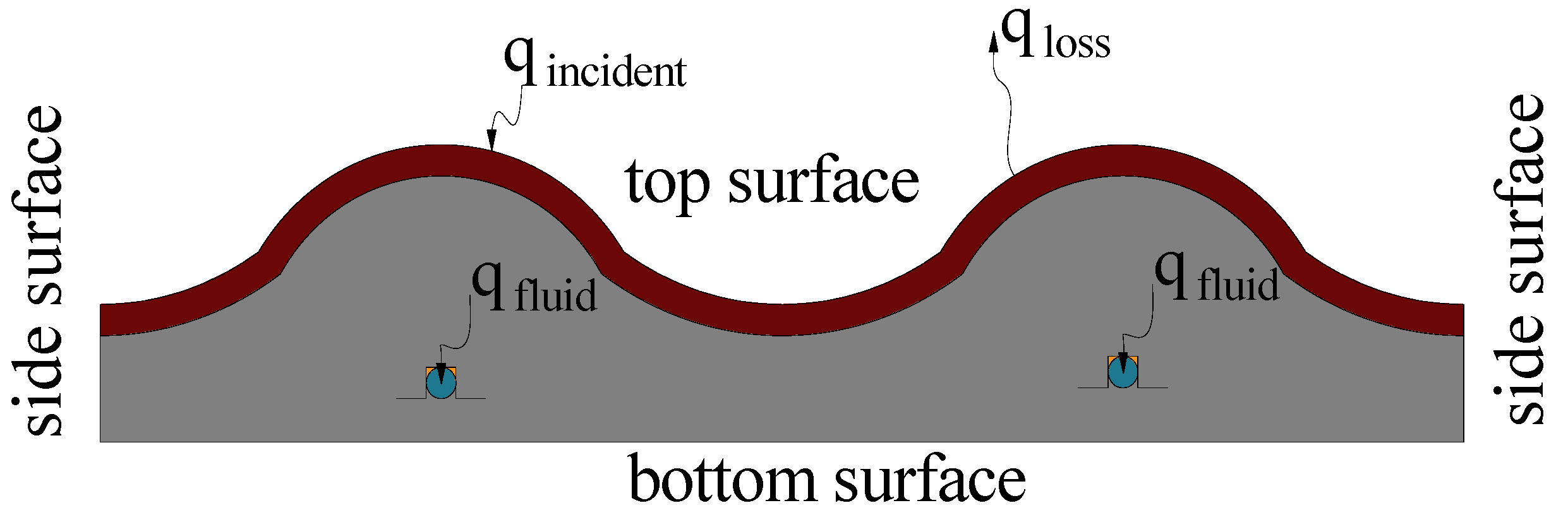
2.3.2.2. Simulation Results and Analysis

The ceramic tile has an absorbtivity of 0.85, and the same emissivity. The climate conditions used were determined in accord with the typical day data from Tianjin. Constant inputs are equal to the daily average values and the solar irradiation and ambient temperature are 400 W/m2 and 0 °C, respectively. The wind speed and dew point are 2.1 m/s and −5.8 °C, respectively. εsky and Tsky were calculated by Equations (9) and (10), Respectively. Figure 7 gives the mesh generated during simulation and the related results, respectively. Figure 7a shows that the mesh is not evenly generated because the size of different component relies on different magnitudes, and in order to save calculation time while maintaining the accuracy, local uneven meshes are needed. Figure 7b and Figure 7c gives the temperature and heat flux distributions among the simulation domain. The temperature difference between the tile surface and the fluid in the tube was no more than 11 °C, and the heat flux was relative evenly distributed, with an average heat flux of 350 W/m2 based the top surface of the roof-integrated collector. The overall area of the roof-integrated collector is about 260 m2, the total heat flow is about 91 kW under the simulation conditions, much higher than the building heat load calculated previously by eQUEST. Therefore, it is feasible to apply such a roof integrated solar collector as a heat source for the heat pump.
Figure 7. The simulation mesh and results. (a) Mesh; (b) Temperature; (c) Heat flux.
Energies 04 00504 g007

2.4. The Coupled Heat Pump
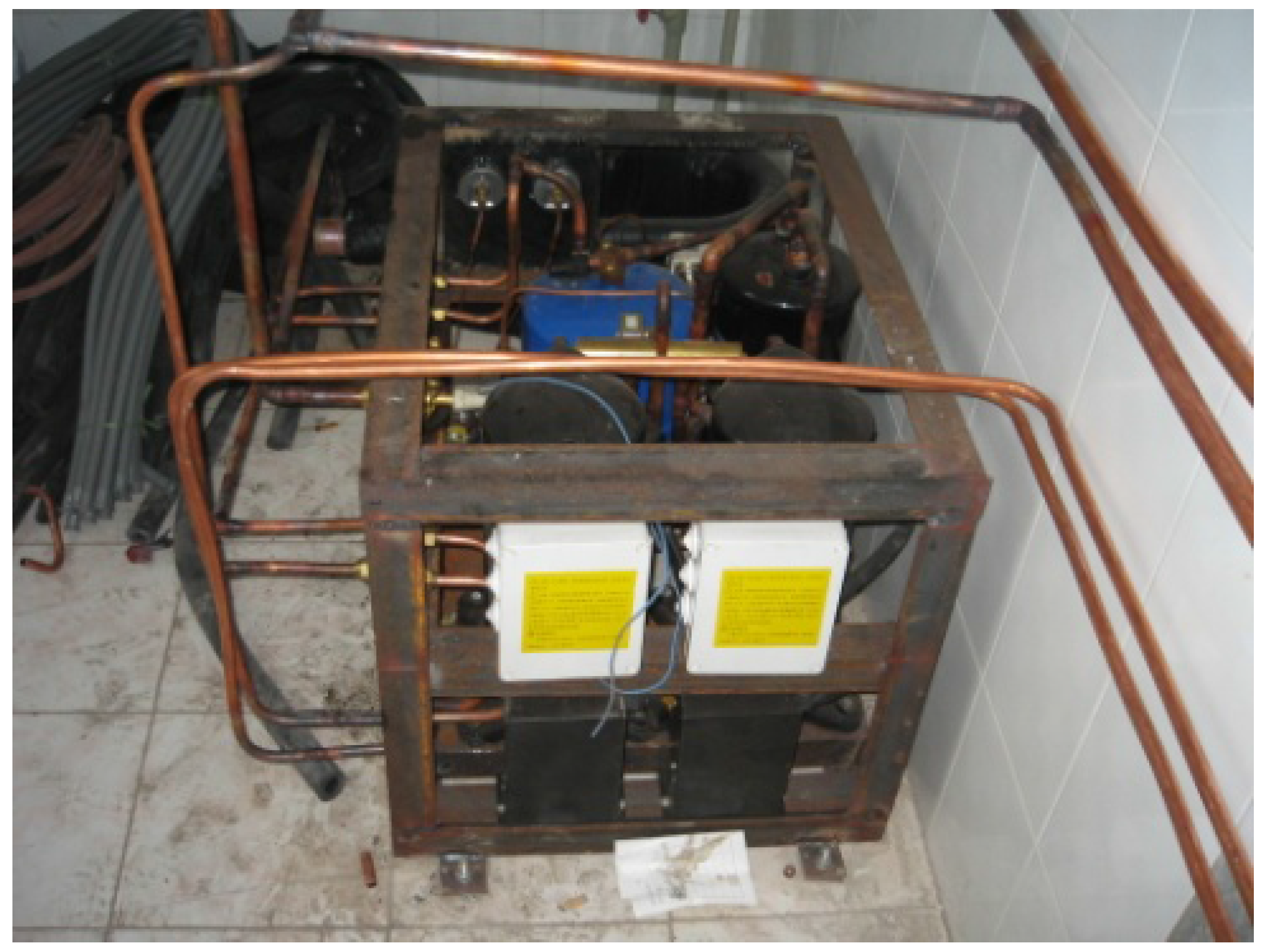
The system used four scroll compressors with single-phase induction motors, whose displacement at 50 Hz is 33.2 m3/h, with a rated power of 8820 W. Figure 8 shows a picture of the actual system. The system also has the function of cooling the building in summer. A thermostatic expansion valve was used for the system, which maintains constant superheat at the inlet of the compressor by regulating the mass flow rate of the refrigerant with the help of a feeler bulb. The temperatures were measured with 0.1 °C precision by thermal resistor sensors at various locations in the system and the building. The power consumption of the system was also measured by a Wattmeter. The heat pump was set on the first floor to ensure system stability and less noise. Table 2 gives the technical specifications of the major equipment.
Figure 8. The picture of the real system.
Energies 04 00504 g008
Table 2. Technical specifications of the major equipment.
NameAmount Technical Parameter
Scroll Compressor4rated cooling capacity of 8.8 kW
Expansion Valve2rated cooling capacity of 19.1 kW
Condenser1heat interchanging area of 6 m2
Evaporator1heat interchanging area of 5 m2
Pump2pumping head of 25 m, flow discharge of 6 m3/h

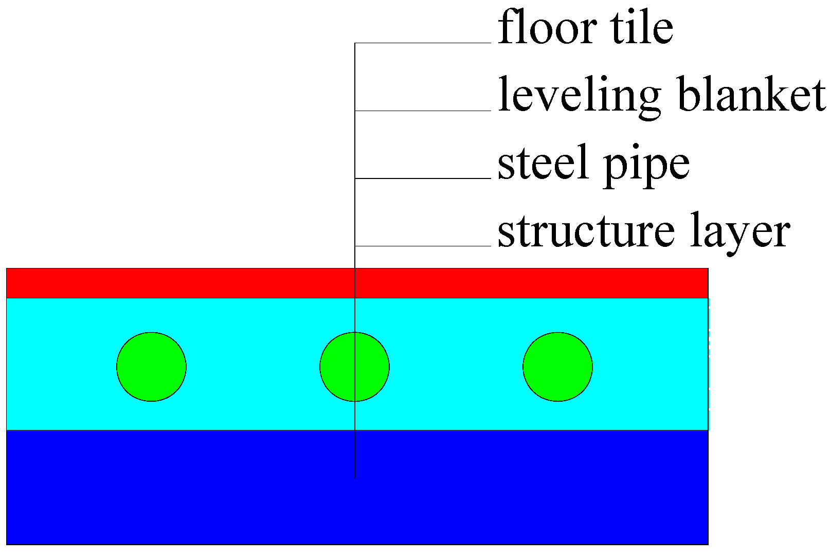
2.5. The Radiant Floor Heating System

Figure 9 shows the schematic structure of the demonstrated radiant floor heating system. Different from the conventional type, the tube buried underneath is galvanized steel tube, not PE. The tube has an inner diameter of 20 mm and the tube thickness is 2.75 mm; the space between two tubes is 400 mm; the depth of buried pipe is 40 mm from tube center to the floor tile top surface. Moreover, the floor construction is much simpler than the conventional one, since no additional layers or thickness are added, compared to the conventional floor construction.

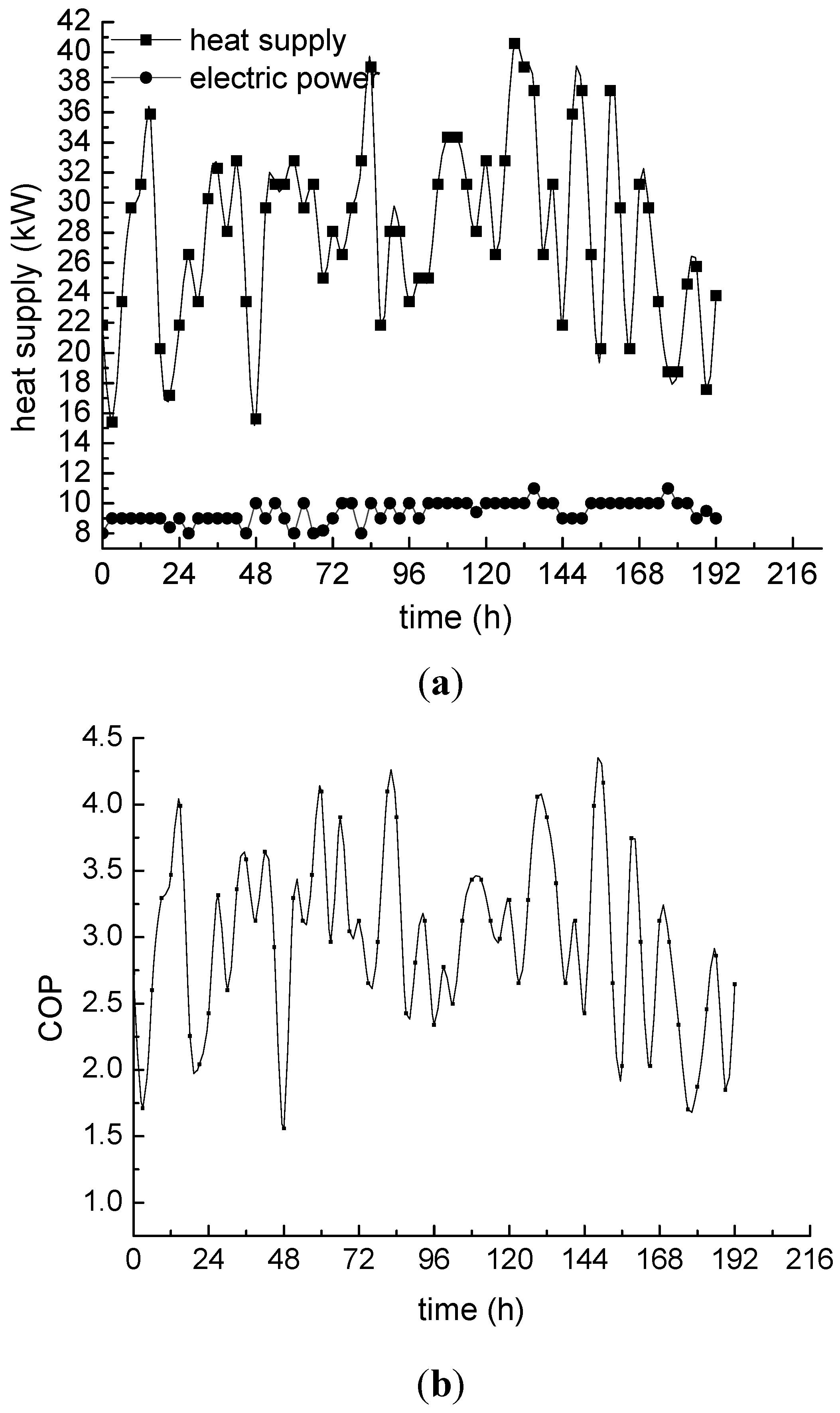
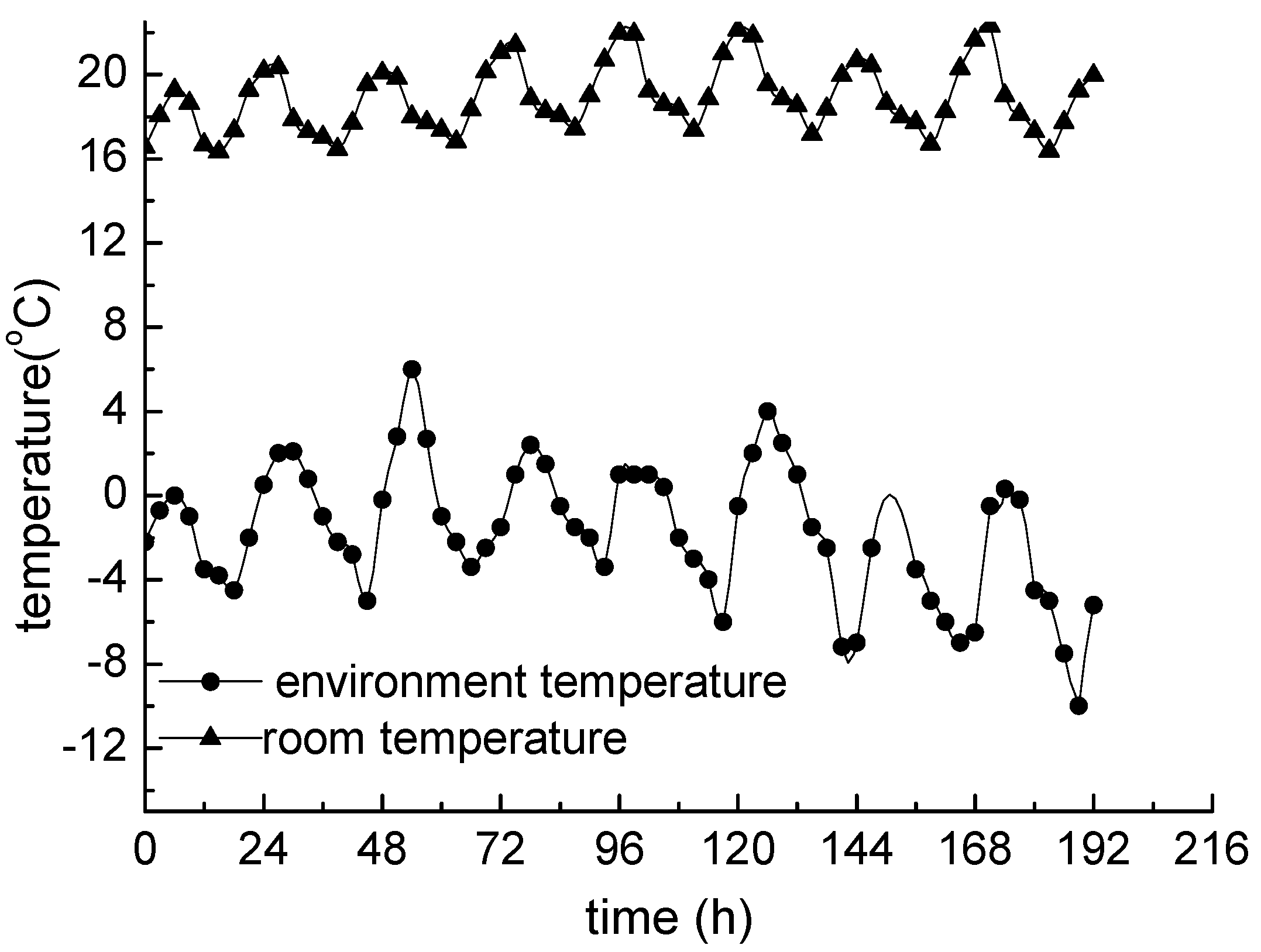
3. Real-Detected Performance of the Solar-Assisted Heat Pump

The real performance of the demonstrated solar-assisted HP system was tested from January 1 to January 8 in 2009. Figure 10 shows the room temperature and for comparison, the outside air temperature. Both curves in the Figure 9 have fluctuations, the reason for this is that large south-facing windows brought in a lot solar heat during the daytime. Meanwhile, the room temperature averaged at 18.9 °C, which meets the design standard in Tianjin city.
Figure 9. Schematic of the radiant floor.
Energies 04 00504 g009
Figure 10. Room temperature and environment temperature during test.
Energies 04 00504 g010
The heat supply and the electric power consumption of the system in the 8 days are shown in Figure 11a.
Figure 11. Energy and performance analysis results of the system. (a) Thermal and electrical energy; (b) COP.
Energies 04 00504 g011
The electricity usage is always less than 10 kW, which is a small value for a villa of 820 m2. Figure 11b gives the calculated COP values for the demonstrated system using the thermal energy supplied and the electricity consumed during the test period. It can be seen that the COP of the heat pump fluctuates depending on the environmental conditions during the test period in winter; the average COP is 2.97, and the maximum value reaches 4.16, a relatively high value for winter weather.

4. Conclusions

In the present study, a SAHP system which consists of a refrigerant filled collector, a scroll compressor and a radiant floor heating unit with a legend roof integrated solar collector was designed and demonstrated. The legend roof integrated collector can provide finished surfaces, weatherproofing, insulation and energy collection. During the winter of 2009, a series of experimental studies were carried out on the SAHP system. Experimental results show that the system can provide a comfortable living space in winter, with an average COP of 2.97 and a maximum COP of 4.16. The multi-functional SAHP system can guarantee long-term operation under different weather conditions and relatively low running costs during wintertime, but its advantages need to be further proven by more experimental and theoretical studies in the future.

Nomenclature:

Cp
specific heat of fluid at constant pressure (J kg−1 K−1);
ha
ambient heat loss coefficient (W m−2 K−1);
hc
convection heat loss coefficient (W m−2 K−1);
hf
fluid heat transfer coefficient (W m−2 K−1);
hr
radiation heat loss coefficient (W m−2 K−1);
I
solar insolation (W m−2);
K
thermal conductivity (W m−1K−1);
kt
thermal conductivity of tile(W m−1K−1);
Pr
Prandtl number;
q
heat flux (W m−2);
Re
Renolds number;
T
temperature (K);
Tf
fluid temperature (K);
Ta
ambient temperature (K);
Tdp
dew point temperature (K);
Tsky
temperature of sky (K);
T
time (s);
V
velocity (m s−1);
ρ
density (kg m−3);
ε
average emittance;
εsky
emittance of the sky;
εt
emittance of the tile;
λ
coefficient of thermal conductivity (W m−1 K−1)

References

  1. Zhai, X.Q.; Wang, R.Z. Experiences on solar heating and cooling in China. Renew. Sustain. Energy Rev. 2008, 12, 1110–1128. [Google Scholar] [CrossRef]
  2. Hartkopf, V.; Loftness, S.; Duckworth, S.; Lee, P.; Drake, J.; Rainer, G. The Intelligent Workplace Retrofit Initiative: DOE Building Studies; The U.S. Department of Energy: Washington, DC, USA, 1994. [Google Scholar]
  3. Bopshetty, S.V.; Nayak, J.K.; Sukhatme, S.P. Performance analysis of a solar concrete collector. Energy Convers. Manag. 1992, 33, 1007–1016. [Google Scholar] [CrossRef]
  4. Chaurasia, P.B.L. Solar water heaters based on concrete collectors. Energy 2000, 25, 703–716. [Google Scholar] [CrossRef]
  5. Bilgen, E.; Richard, M.A. Horizontal concrete slabs as passive solar collectors. Sol. Energy 2002, 72, 405–413. [Google Scholar] [CrossRef]
  6. Medved, S.; Arkar, C.; Cerne, B. A large-panel unglazed roof-integrated liquid solar collector––Energy and economic evaluation. Sol. Energy 2003, 75, 455–467. [Google Scholar] [CrossRef]
  7. Abbott, A.B. Analysis of Thermal Energy Collection from Precast Concrete Roof Assemblies. Master’s Thesis, Virginia Polytechnic Institute and State University, Blacksburg, VA, USA, 2004. [Google Scholar]
  8. Kara, O.; Ulgen, K.; Hepbasli, A. Exergetic assessment of direct-expansion solar-assisted heat pump systems Review and modeling. Renew. Sustain. Energy Rev. 2008, 12, 1383–1401. [Google Scholar] [CrossRef]
  9. MacArthur, J.W.; Palm, W.J.; Lessmann, R.C. Performance analysis and cost optimization of a solar-assisted heat pump system. Sol. Energy 1978, 21, 1–9. [Google Scholar] [CrossRef]
  10. Freeman, T.L.; Mitchell, J.W.; Audit, T.E. Performance of combined solar–heat pump systems. Sol. Energy 1979, 22, 125–135. [Google Scholar] [CrossRef]
  11. Pedersen, P.V. System design optimization for large building integrated solar heating systems for domestic hot water. Sol. Energy 1993, 50, 267–273. [Google Scholar] [CrossRef]
  12. Kaygsuz, K.; Ayhan, T. Exergy analysis of solar-assisted heat-pump systems for domestic heating. Energy Int. J. 1993, 18, 1077–1085. [Google Scholar] [CrossRef]
  13. Smith, R.R.; Hwang, C.C.; Dougall, R.S. Modeling of a solar-assisted dessicant air conditioner for residential building. Energy Int. J. 1994, 19, 679–691. [Google Scholar] [CrossRef]
  14. Abou-Ziyan, H.Z.; Ahmed, M.F.; Metwally, M.N.; EI-Hameed, A. Solar-assisted R22 and R134a heat pump systems for low-temperature applications. Appl. Therm. Eng. 1997, 17, 455–469. [Google Scholar] [CrossRef]
  15. Badescu, V. Model for a solar-assisted climatization system. Energy Int. J. 1998, 23, 753–766. [Google Scholar] [CrossRef]
  16. Torres, R.; Picon, N.M.; de Cervantes, G.J. Exergy analysis and optimization of a solar-assisted heat pump. Energy Int. J. 1998, 23, 337–344. [Google Scholar] [CrossRef]
  17. Huang, H.; Xinshi, G.; Yuehong, S. Theoretical thermal performance analysis of two solar-assisted heat-pump systems. Int. J. Energy Res. 1999, 23, 1–6. [Google Scholar] [CrossRef]
  18. Ito, S.; Miura, N.; Wang, K. Performance of a heat pump using direct expansion solar collectors. Sol. Energy 1999, 65, 189–196. [Google Scholar] [CrossRef]
  19. Esen, M. Thermal performance of a solar-aided latent heat store used for space heating by heat pump. Sol. Energy 2000, 69, 15–25. [Google Scholar] [CrossRef]
  20. Badescu, V. Model of a solar-assisted heat pump system for space heating integrating a thermal energy storage unit. Energy Build. 2002, 34, 715–726. [Google Scholar] [CrossRef]
  21. Badescu, V. Model of a space heating system integrating a heat pump, photothermal collectors and solar cells. Renew. Energy 2002, 27, 489–505. [Google Scholar] [CrossRef]
  22. Badescu, V. First and second law analysis of a solar assisted heat pump based heating system. Energy Convers. Manag. 2002, 43, 2539–2552. [Google Scholar] [CrossRef]
  23. Lu, A.; Charters, W.W.S.; Chaichana, C. Solar heat pump systems for domestic hot water. Sol. Energy 2002, 73, 169–175. [Google Scholar] [CrossRef]
  24. Badescu, V. Model of a thermal energy storage device integrated into a solar assisted heat pump system for space heating. Energy Convers. Manag. 2003, 44, 1589–1604. [Google Scholar] [CrossRef]
  25. Hawlader, M.N.A.; Chou, S.K.; Jahangeer, K.A.; Rahman, S.M.A.; Eugene, L.K.W. Solar assisted heat-pump dryer and water heater. Appl. Energy 2003, 74, 185–193. [Google Scholar] [CrossRef]
  26. Sattari, S.; Farhanieh, B. A parametric study on radiant floor heating system performance. Renew. Energy 2006, 31, 1617–1626. [Google Scholar] [CrossRef]
  27. Cho, S.H.; Zaheer-uddin, M. An experimental study of multiple parameter switching control for radiant floor heating systems. Energy 1999, 24, 433–444. [Google Scholar] [CrossRef]
  28. China Meteorological BureauClimate Information CenterClimate Data OfficeTsinghua UniversityDepartment of Building Science and TechnologyChina Standard Weather Data for Analyzing Building Thermal Conditions; China Building Industry Publishing House: Beijing, China, 2005; in Chinese.
  29. James, J. eQUEST Introductory Tutorial; Hirsch & Associates: Anaheim, CA, USA, 2004; pp. 3–4. [Google Scholar]
  30. Medrano, M.; Brouwer, J.; McDonell, V.; Mauzey, J.; Samuelsen, S. Integration of distributed generation systems into generic types of commercial buildings in California. Energy Build. 2008, 40, 537–548. [Google Scholar] [CrossRef]
  31. Bejan, A.; Kraus, A.D. Heat Transfer Handbook; John Wiley & Sons, Inc.: Hoboken, NJ, USA, 2002; pp. 829–831. [Google Scholar]
  32. Duffie, J.A.; Beckman, W.A. Solar Engineering of Thermal Processes; John Wiley and Sons, Inc.: Hoboken, NJ, USA, 1991; pp. 164–165. [Google Scholar]
  33. Duffie, J.A.; Beckman, W.A. Solar Engineering of Thermal Processes; John Wiley and Sons, Inc.: Hoboken, NJ, USA, 1991; pp. 148–149. [Google Scholar]
  34. Clark, E.; Berdahl, P. Radiative Cooling: Resource and Applications; Proceedings of the Passive-Cooling Workshop: Amherst, MA, USA, 1980; pp. 177–212. [Google Scholar]

