Article

Transient Response Improvement of Microgrids Exploiting the Inertia of a Doubly-Fed Induction Generator (DFIG)

University of Patras, Panepistimioupoli, Patras, Rio GR26500, Greece
*
Author to whom correspondence should be addressed.
Energies 2010, 3(6), 1049-1066; https://doi.org/10.3390/en30601049
Submission received: 12 April 2010 / Revised: 26 April 2010 / Accepted: 30 April 2010 / Published: 1 June 2010
(This article belongs to the Special Issue Wind Energy)

Abstract

:
Storage devices are introduced in microgrids in order to secure their power quality, power regularity and offer ancillary services in a transient period. In the transition period of a low voltage microgrid, from the connected mode of operation to the islanded mode of operation, the power unbalance can be partly covered by the inertia energy of the existing power sources. This paper proposes fuzzy local controllers exploiting the inertia of a Wind Turbine (WT) with a Doubly Fed Induction Generator (DFIG), if such a machine exists in the microgrid, in order to decrease the necessary storage devices and the drawbacks that arise. The proposed controllers are based in fuzzy logic due to the non linear and stochastic behavior of the system. Two cases are studied and compared during the transient period where the microgrid architecture and the DFIG controller differ. In the first case, the understudy microgrid includes a hybrid fuel cell system (FCS)-battery system and a WT with a DFIGURE. The DFIG local controller in this case is also based in fuzzy logic and follows the classical optimum power absorption scenario for the WT. The transition of the microgrid from the connected mode of operation to the islanded mode is evaluated and, especially, the battery contribution is estimated. In the second case, the battery is eliminated. The fuzzy controller of the DFIG during the transition provides primary frequency control and local bus voltage support exploiting the WT inertia. The response of the system is estimated in both cases using MATLAB/Simulink software package.

1. Introduction

Power Systems mainly consist of large generation plants supplying distant loads through the utility grids. In recent years, a number of factors have gradually led to changes in this structure. Small generators of some MW have already been dispersed throughout the transmission grid (DG). The new concept is the distribution of smaller units throughout the distribution system as near as possible to the consumer loads. The DGs have to change from passive appendage to primary energy supply, remaining connected to the grid under serious disturbances and offering ancillary services. Under this operation philosophy, DGs must support the grid from local disturbances, as central generation stations support high voltage systems in the transient period. This can be achieved through the control of the DGs electronic interface to the main grid and the energy storage plants. These controllable DGs (<100 kWe) connected to the distribution grid, the energy storage devices and the local loads, comprise the concept of a microgrid. In other words, the microgrid can be seen as a miniature of a large interconnected grid that can provide the demanded power and can also change from interconnected to islanded mode of operation [1]. The microgrid concept is the effective solution for the control of grids with high level of DG penetration [2].
The control of the microgrid has to be reliable, flexible and according to system specifications. The DGs of the microgrid have to cooperate in order to cover the local load needs for active and reactive power either under local disturbances or under islanding operation mode. The first layer of control of the DGs is a “peer-to-peer” controller [3] based on local information. This way, any DG can be integrated into the microgrid operating in “plug and play” mode [4].
Storage devices are a main feature for proper functionality of the microgrid. They can be coupled to the microgrid through an electronic interface either as creative sources or combined with other microsources, forming hybrid systems. Storage devices usage ensures the unified dynamic performance of the microsources achieving power quality and the “plug and play” feature. Reliability and continuity of service is also promoted by controlling the power delivered by the storage device. In other words, storage devices should provide, at any moment, the difference between the load demand and the available source power [4]. This way, microsources with slow dynamic response such as fuel cell systems (FCS) or microsources with uncertain prime mover, such as wind turbines, are prevented from stalling under fast or heavy load transients. The sizing, the incorporated controller and the response speed of a storage device highly depend on the microgrid configuration, the system requirements and the type of microsources included. The main drawback of the storage device usage in real systems is that it increases the system cost. This especially applies for distribution grids.
In order to exploit the inertia of the WT existing in a microgrid, their electronic interface has to incorporate controllers that provide primary frequency and voltage support. In former studies the usual “peer-to-peer” controller of the DGs converters uses the power vs. frequency droop characteristics in order to produce the active and reactive reference combined with classical PI controllers as it is mentioned in the review of state-of -the- art controllers in [3]. In [5] a control approach is applied on a DFIG in order to improve the dynamic behavior of a microgrid at the mean voltage side. The DFIG can switch from grid connected control strategy to islanding mode control strategy. The latter consists of the frequency control loop and the voltage regulating loop incorporated into the rotor side controller of the DFIG using classical PI controllers. In [2] the primary, secondary and tertiary control algorithms are designed and tested in an experimental setup. The local controller uses the classical droop equation while the secondary and tertiary controllers aim at power quality and economic optimization respectively. For the latter, the converters of the DGs communicate via the Internet. In [6] the classical local controller applied to the converters of a DFIG is combined with a pitch controller for a better dynamic response of a microgrid at the mean voltage side. In [7], the active power regulation is achieved through the classical controller combined with a frequency restoration strategy while three different strategies for reactive power regulation are adopted. The microgrid dynamic behavior and the parameters of the DGs are mathematically investigated. In [8] a microgrid architecture is presented in order to avoid any need of storage devices or load shedding. The microgrid stability was also compared with conventional controllers and fuzzy-neural-network controllers proving that the latter appears to provide a better performance in stabilizing the system.
The droop equation combined with classical control can lead, under certain operational conditions, the microgrid to become unstable, while the stability enhancement for these cases needs sophisticated calculations [9]. In addition, the non-linearity of the microgrid makes the implementation of fuzzy logic controllers at the DGs converters an attractive proposal. Moreover, fuzzy logic enforces the “plug and play” operation for the DGs as the needed adjustments are minor, due to the flexibility of fuzzy logic, and easier, due to the linguistic variables used.
This paper proposes including fuzzy based local controllers for the DFIG of a WT into a microgrid which is connected to a weak distribution grid. The proposed controller exploits the WT inertia and offers primary frequency and voltage support to the microgrid in the transient period from the connected to the islanded mode. This exploitation of the inertia energy can replace part of the storage device energy needed in the transient period and to reduce battery size. To prove this, two cases are studied.
In the first case, a FCS with a battery bank and a WT with DFIG are connected to the microgrid. The DFIG fuzzy controller maintains the DFIG under optimum power absorption operation, thus, the inertia of the WT is not exploited in transient period.
In the second case study, the battery bank is eliminated as it is used only in the transient period since the FCS and the DFIG cover the needs of the loads in steady state. In real systems though, the storage devices mainly contribute in steady state and, therefore, their size can only be reduced. The DFIG fuzzy controller in this case exploits the inertia and offers frequency and voltage support to the microgrid in transient period. The microgrid response is estimated when a transition from interconnected mode to islanding operating mode occurs. The microgrid under study is simulated with Matlab/Simulink software, reproducing a real microgrid as it is described in [3].
In the following section, the microgrid architecture is analyzed and the models of the DGs are presented. In the third section, the designed controller is analyzed for both case studies. In the fourth section, the simulation results are presented and the last section concludes the paper.

2. Architecture of the Microgrid

The microgrid concept was put forward in 2001. Since then, several microgrids with multi-energy generators (MGMEG) and storages have been built in labs in universities and institutes all over the world [3]. The majority of the DGs are connected to the microgrid via electronic converters, e.g., voltage source inverters (VSI). The structure of the simulated microgrid resembles those developed in labs and includes two different microsources. As seen in [8], the microgrid architecture that combines different DGs is more practical as the storage device equipment or controllable loads can be reduced. The FCS, either combined with a battery bank or not, is connected to the AC feeder via a VSI and the DFIG is connected directly to the feeder. In both DGs, the “peer-to-peer” controller is based on fuzzy logic and the VSI local controllers are designed in “plug and play” operation mode. The “peer-to-peer” controllers imply that through the electronic interface the DGs can provide the local grid with the demanded active and reactive power without a central controller and communication links among microsources. The “plug and play” operation mode implies that a microsource can be added to the microgrid without reengineering the control and protection of units that are already part of the system. It is expected that, in steady state, a microgrid central controller should coordinate DG to optimize operation, minimizing active power losses and maintaining a flat voltage profile. The structure of the understudy microgrid is presented in Figure 1 and the data are given in the appendix.
Figure 1. The Microgrid Configuration.
Energies 03 01049 g001

2.1. Description and Modeling of the Hybrid System

The configuration of the DC-side of the hybrid system is shown in Figure 2 and stands for both cases studied. The hybrid system of this study consists of a proton exchange membrane type (PEM) fuel cell system (FCS) and a battery bank.
The adopted mathematical model of the FCS is fitted to this paper’s requirements. The FCS includes the following four main flow systems that are responsible for four main transient phenomena:
  • Hydrogen supply system to the anode.
  • Air supply system to the cathode.
  • De-ionized water as a coolant.
  • De-ionized water to the humidifier to humidify the membrane.
It is assumed in our study that a compressed hydrogen tank is available for the first flow system and that the hydrogen flow in the anode is adjusted according to the air flow in the cathode through a valve. For the second flow system, the “Chopper 2” (Figure 2) controls the supplied DC power to a DC motor that drives a compressor, which controls the air flow in the cathode. Therefore, the rate of the power change at the FCS output is limited by the overall inertia of the compressor and the motor. For the third subsystem, as the study period of the system lasts for a few seconds, it is assumed that the temperature of the fuel cell stack remains constant (80 °C) as the thermal dynamics are very slow with a time constant of about 102 s. In the fourth system, it is assumed that the membrane of the model is fully humidified as the membrane hydration has a transient phase of about 10 s. It must be mentioned that the air flow dynamics and the humidity management define the FCS response. By assuming that the membrane is fully humidified, the designed controller for the second subsystem can safely be decoupled from the humidity. Also, the “double-layer charging effect” has been neglected, taking into account that its time constant is almost 10−19 seconds. The FCS is designed to be self‑powered, i.e., every auxiliary component of the FCS must be supplied by the FCS power, especially the air supply system. At the output of the FCS, the “Chopper 1” is connected so that the DC voltage is boosted and regulates the FCS’s output, without exceeding the FCS capabilities.
Figure 2. DC Side Configuration.
Energies 03 01049 g002
The battery bank, when connected, supports the DC voltage, keeping its deviations within certain limits and supports FCS’s performance under fast load changes as FCS dynamics are slow. Since the FCS has low dynamic response, the battery covers the fast load changes and FCS oxygen starvation is avoided. In addition, when our system reaches steady-state, the battery current is forced to zero in order that the FCS supplies all demanded power. The model of the battery used in the study (Figure 3) is adopted from the MATLAB software package (SimPowerSystems library) and is parameterized according to the system requirements. The variables E, Εο, Κ, Q, A and B denote the non load voltage, the constant voltage, the polarization voltage, the battery capacity, the exponential voltage and the exponential capacity, respectively. The battery type is given in the appendix.
Figure 3. The Battery Model used in the study.
Energies 03 01049 g003
The hybrid system already described interfaces with the ac-side system through a voltage source inverter (VSI) in order to achieve the independent control of the active and reactive power. An L-C filter is located at the VSI output followed by a step-up transformer. The transformer is connected to the AC feeder of the weak distribution grid.

2.2. Description and Modeling of the DFIG

The DFIG system can independently provide voltage and frequency regulation capabilities via the rotor current control. The basic configuration of the DFIG system is presented in Figure 4. The main parts of the system are: the wind turbine model, the model of the inverters and the induction generator model.
Figure 4. The wind turbine and the DFIG system.
Energies 03 01049 g004
The power captured by the wind turbine is converted into electrical power by the induction generator and transmitted to the grid by the stator and the rotor windings. The mathematical equations of the wind turbine model are given below.
The power obtained from a given wind speed is expressed by the following equation:
P w = 0.5 ρ π R 2 v 3 C p ( λ , β )
with ρ being the air density, R the effective radius of the turbine, ν the mean value of the wind speed at the height of the rotor axis, Cp the power coefficient of the wind turbine and β the pitch angle.
The tip speed ratio is defined as
λ = ω w R / v
The mechanical torque is defined as
T w = P w / ω w
with ωw being the wind turbine rotor speed.
The coefficient Cp is defined as:
C p = c 1 ( c 2 λ c 3 β c 4 ) e c 5 λ + c 6 λ
The coefficient values are given in the appendix.
The model of the converters is the analytical model for voltage source converters given in the software package MATLAB (SimPowerSystems library). The equations of the wound induction generator model and its parameters were adopted by the same library. It has to be mentioned that in this simulation study, a two-mass shaft model has been considered as the transient behavior of the system is evaluated.

3. Fuzzy Controller Analysis

As briefly mentioned in the introduction, the local controllers of the DGs are based in fuzzy logic due to its flexibility, adaptiveness and to the non-linearity of the system. The fuzzy controllers are non linear in nature and, therefore, a robust performance under disturbances is expected. Analytically, the four main flow subsystems of the FCS briefly mentioned in the previous section, and the auxiliary subsystems that are beyond the scope of this paper, establish a non linear FCS. In addition, the presence of non linear and cross-coupling terms of the DFIG dynamics form a microgrid, which is intensively non linear. Some key points of great significance for the system efficiency and performance, outlined below, enhance the application of a fuzzy based intelligent control. As for the hybrid system, it is significant for the compressor motor controller (“Chopper 2”) to have a good dynamic response during fast load changes so that the FCS voltage does not drop dramatically leading to oxygen starvation. Secondly, the “Chopper 1” controller has to act simultaneously with the fuel flow control achieving stability and accuracy while minimizing overshooting and current rippling. The DFIG and hybrid system VSI controllers have to meet the same requirements. The design of the fuzzy controllers does not require a precise mathematical modeling or sophisticated computations that in many cases lack efficiency and do not perform well. The latter indicates that fuzzy logic is more suitable and practical in real systems as the engineer can tune the local controller easier via the linguistic variables (easy engineering).

3.1. Hybrid System Controller

The local controller of the hybrid system consists of five different fuzzy local controllers. The fuzzy controllers (Fc) are designed from a heuristic knowledge of the system. Of course, they are thoroughly iterated by system simulation studies in order to be fine tuned. The advantage of this method is the fast convergence, as it provides adaptively decreasing step size in the search for the adequate output. The analytical description of the controllers was done in [10]. The designed controller did not change in order that the hybrid system becomes integrated into the microgrid but some membership functions (MF) of the controllers were tuned for better response enhancement. The following is a brief description of the controllers.
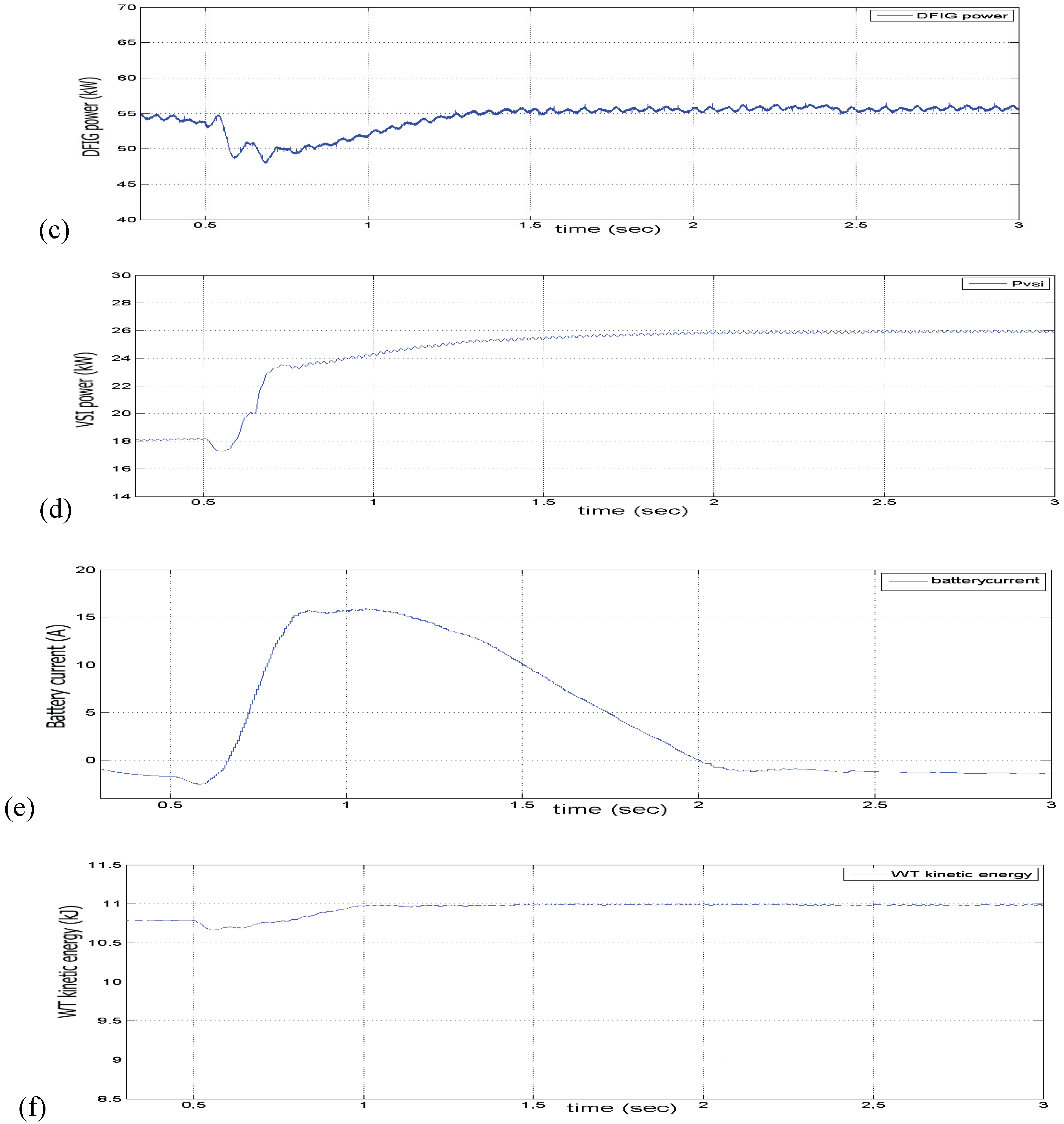
“Chopper 1” control: As already mentioned, the battery bank—when coupled to the DC side—supports the FCS when fast transient phenomena occur, as the FCS has slow dynamics and certain technical limitations. In the steady state, the FCS of the study must provide all of the demanded power and the battery bank supplying current has to be zero. The Chopper 1 control includes the Fc 1 and Fc 2. The Fc 2, through the duty cycle of “Chopper 1”, ensures that the FCS provides the demanded power by the AC-side and the demanded power by the DC-motor. The Fc1 ensures that the battery current is forced to zero in steady state. For the case study in which the battery is missing, the Fc1 controller loop is eliminated from “Chopper 1” controller.
“Chopper 2” control: The Fc3 constitutes the Chopper 2 control and determines, through its duty ratio, the power that the DC-motor absorbs and thereby regulates the air flow supplied by the compressor to the FCS. According to the pressure variation of the supplied air, the supplied hydrogen from the hydrogen tank is regulated through a valve, and this regulates the output power of the FCS according to the power demanded by the system without oxygen starvation. In our study, the hydrogen flow is regulated to the oxygen flow through a simple PI controller. The indication of oxygen starvation is the excess oxygen ratio λO2, which is the ratio of oxygen supplied to oxygen used in the cathode. The optimum value of λO2 is taken as equal to 2 where, for our chosen FCS, the net deliverable power is about maximum.
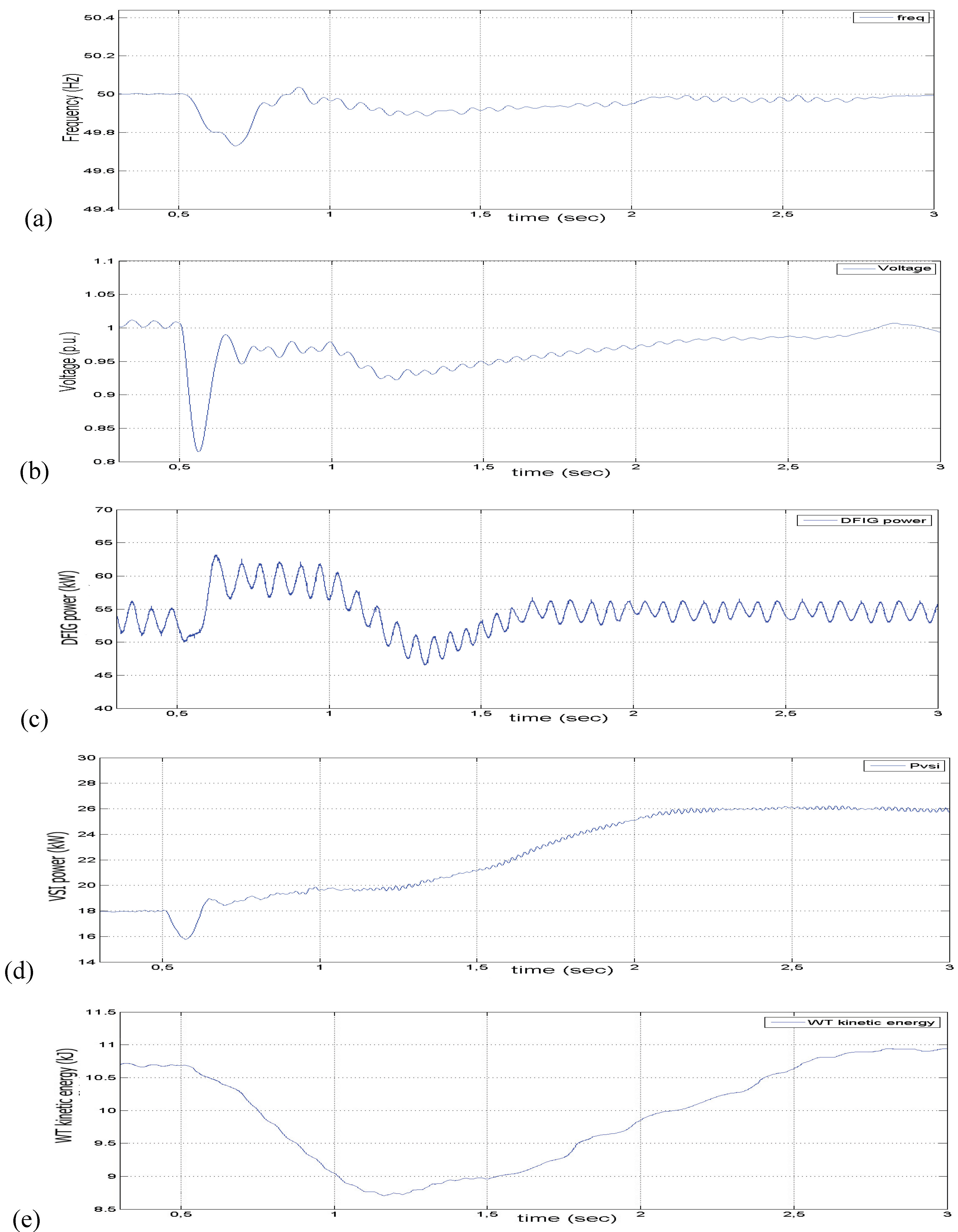
VSI control: The VSI control consists of the Fc4 and Fc5. Through the IGBT’s switching of the VSI, controllers 4 and 5 ensure that the hybrid system provides a part of the demanded active and reactive power by the AC side when a local disturbance occurs or after the distribution grid is disconnected. After simulation tests in our system, the dependency of the voltage magnitude from the active power was found stronger than that of the reactive power. This happens as the distribution grid of our study is weak and has a low short circuit ratio and the distribution lines have a low X/R ratio 0.5. The control of the active power is achieved through the modulation index (mi) of the PWM method. The value of mi is determined by the Fc4. The control of the reactive power is achieved through shifting the phase angle on the sinusoidal reference signal of the PWM method. The Fc5 determines the shift value.

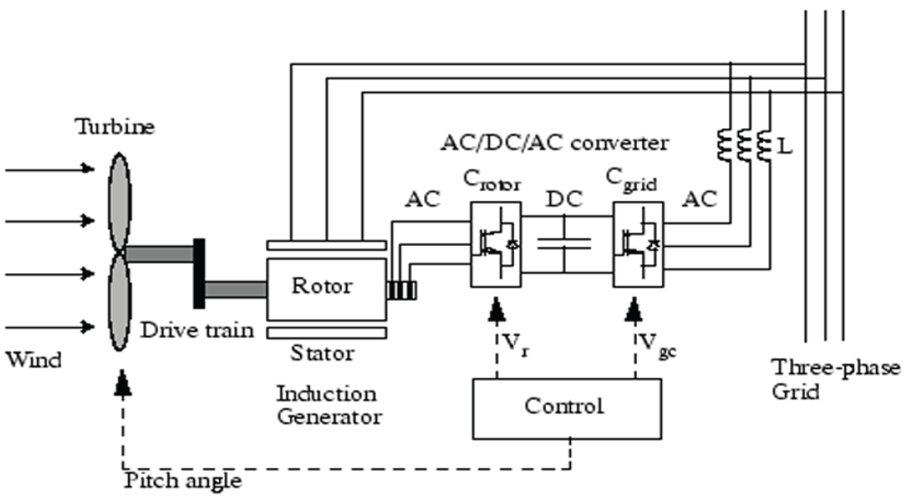
3.2. DFIG System Controller

The DFIG controller comprises the control applied to the grid-side converter (Cgrid), the control applied to the rotor-side converter (Crotor) and the pitch control (Figure 4). In this study, the pitch control is not applicable as the wind speed is assumed to be lower than the predefined limit (18 m/s). So, the angle of the pitches remains the same during the simulation study.
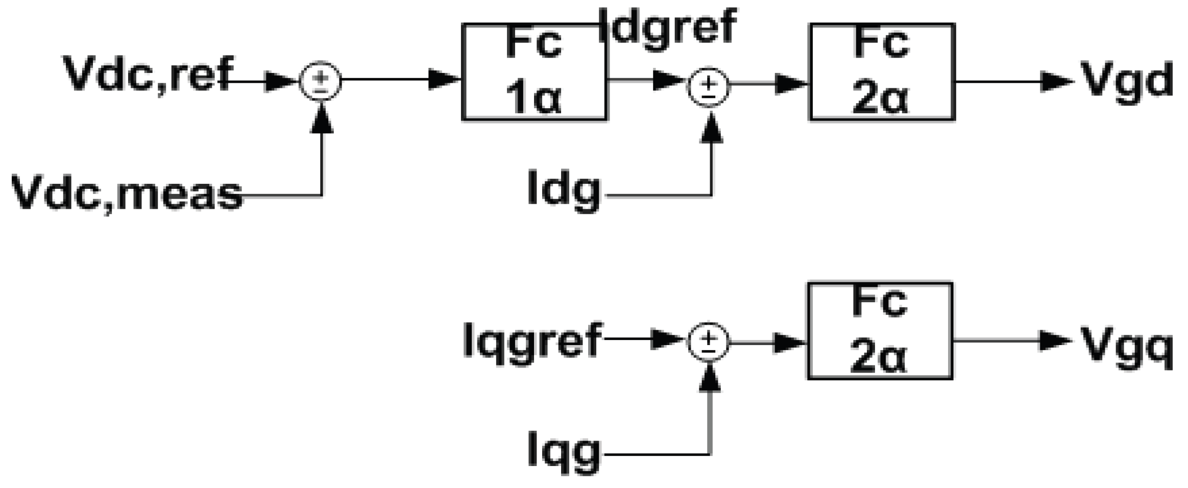
Cgrid control: This control regulates the independent exchange of active and reactive power between the converter and the local grid. This controller focuses on regulating the DC- ink voltage. The applied vector control is based on a synchronously rotating, grid-flux oriented d-q reference frame, meaning that the d-axis is aligned with the grid voltage and the q component is zero. The d component of the converter current regulates the DC-link voltage and the q component of the converter current regulates the reactive power. The control configuration is shown in Figure 5. The Vdc,ref signal is the reference value for the DC-link voltage and the Vdc,meas signal is the measured DC-link voltage. Τhe deviation of the measured voltage from the reference value drives the Fc1α. The reference value of the d component of the output current (from the grid side) is the Fc1a output. The deviation of the measured current from the reference value drives the Fc2α, whose output is the control signal Vgd. The reference value of the q component of the output current, Ιqgref, is zero. The deviation of the measured signal from the reference value drives the Fc2α and its output is the control signal Vgq. It is preferrable for the reactive power to be regulated through the Crotor in order that the electronics rating remains low. Moreover, limiters are placed in order that the currents don’t exceed the electronics limitations. The controller already described remains the same for both case studies.
Figure 5. Cgrid control of the DFIG for both study cases.
Energies 03 01049 g005
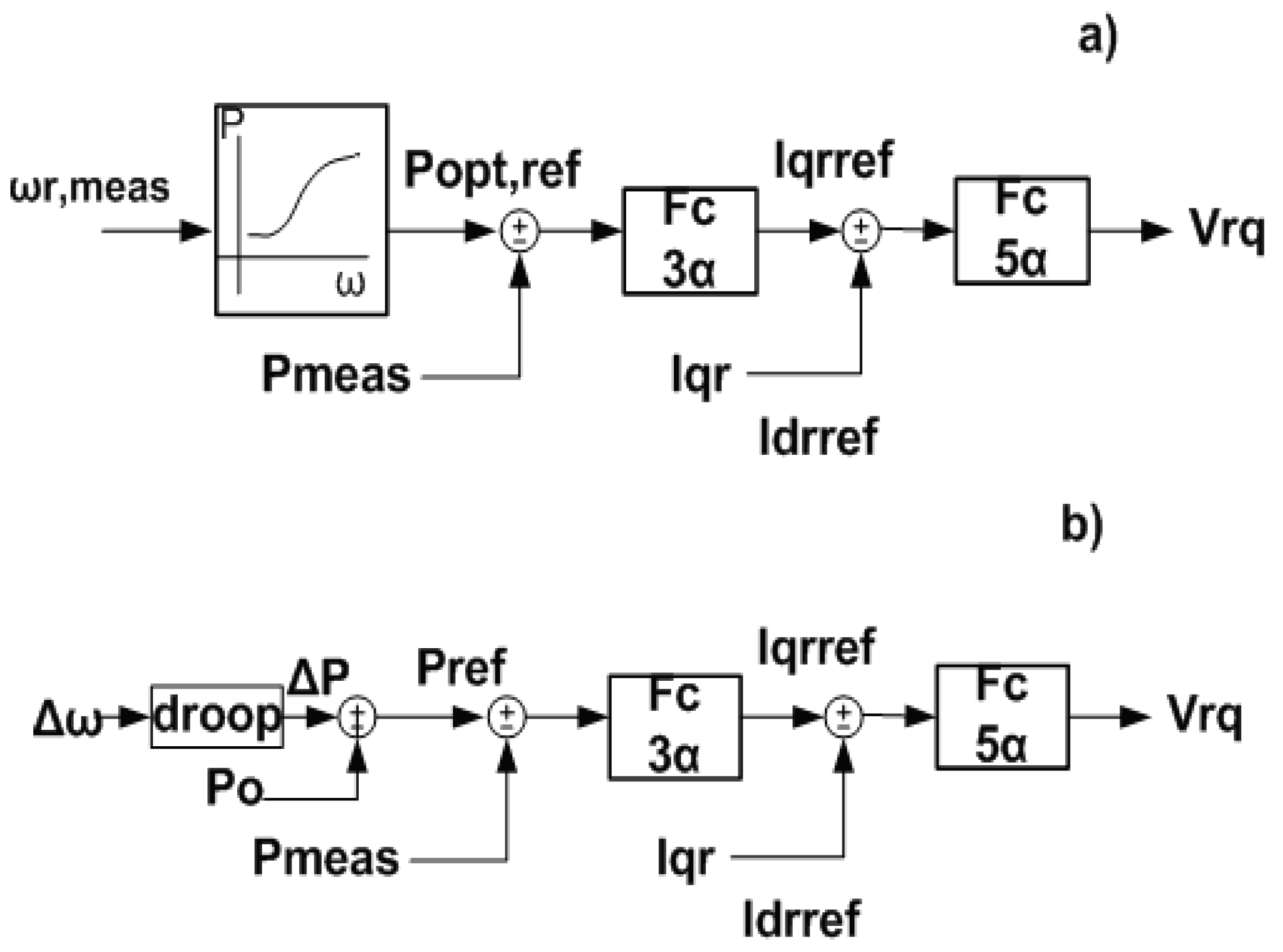
Crotor control: This control independently regulates the active and reactive power of the stator. The applied vector control is based on a synchronously rotating, stator-flux oriented d-q reference frame. Meaning that the d-axis is aligned with the vector of the stator magnetic flux and the q axis is zero. The active power is regulated via the q component of the rotor current and the reactive power via the d component.
The active power controller differs in the two case studies and its configuration is shown in Figure 6. When the microgrid includes a battery, the active power reference point of the DFIG is determined by a look-up table as shown in Figure 6(a). Therefore for a given generator speed, the optimum reference value of the power is determined for a certain wind speed. The deviation of the measured active power from its reference value at the DFIG output Pmeas is driven to Fc3α, whose output is the q component of the reference value of the rotor current, Iqrref. The reference value is compared to the measured q component of the rotor current and drives the Fc5α, whose output is the control signal Vrq.
In the second case study, the droop equation has been incorporated into the active power controller and the generator speed can be different from its optimum value. The controller forces DFIG to supply instant frequency and voltage support exploiting the WT inertia in transient conditions. The active power deviations ΔΡ is expressed by the following droop equation:
ΔP = k Δω
with k being the droop coefficient and Δω the deviations of the frequency measured at the output of the DFIG from its nominal value. The power deviations are added to the initial active power production of the DFIG Po, forming the reference value for active power Pref. It has to be clarified that the fuzzy controllers designed for both cases are the same. This is due to the fuzzy logic adaptive nature and the design of the controllers that decrease the step size in the search of the adequate output.
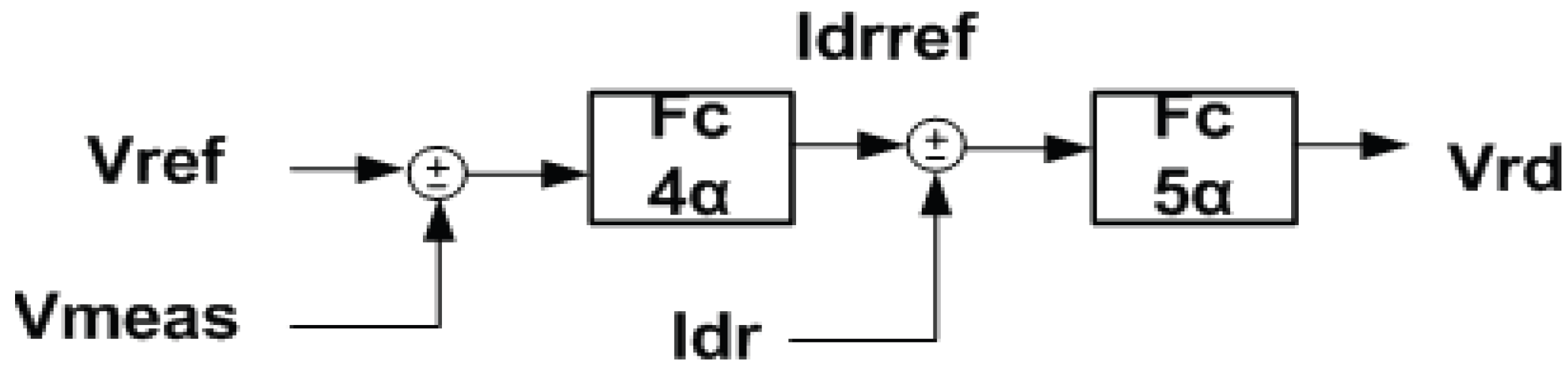
The terminal voltage controller is the same for both case studies and its configuration is shown in Figure 7. The reference value of the voltage is compared to the measured voltage at the generator output and drives the Fc4α , whose output is the d component of the reference value of the rotor current Idrref. The deviation of the measured d component of the rotor current from the reference value drives the Fc5α whose output is the control signal Vrd.
Figure 6. (a) Active power control of the DFIG in study case with battery included (b) active power control of the DFIG in study case without battery.
Energies 03 01049 g006
Figure 7. Terminal voltage control of the DFIG for both cases.
Energies 03 01049 g007
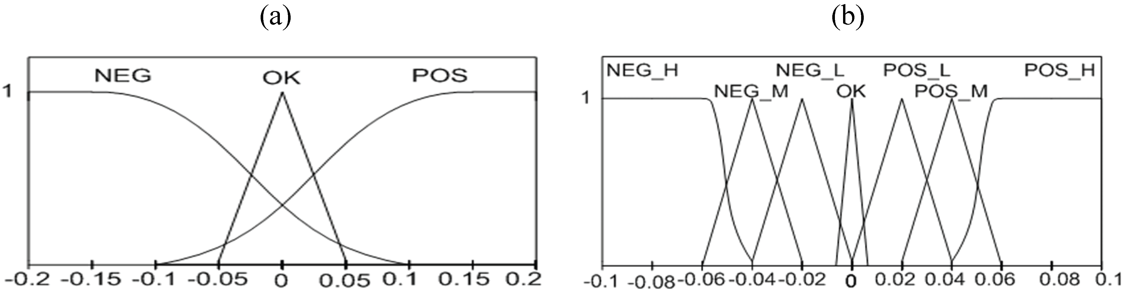
The design of the Fc3a is presented below as a representative case of the processes followed in all the Fcs. Τhe input of the Fc3a is the error between the measured active power Pmeas and the reference value (Popt,ref or Pref). The output of the Fc3a is the deviations of the q component of the reference value of the rotor current, ΔIqrref whose values are added together in every simulation step in order to comprise the Iqrref value at steady state (in p.u.) according to the following equation:
I qrref new = I qrref old + Δ I qrref ,  where :   I qrref n e w  the new value of the control signal . I qrref old  the old value of the control signal .
The fuzzy variables of the input of the Fc3a are expressed by the following linguistic variables: : “positive (POS)”, “ok (OK)”, “negative (NEG)”.The fuzzy variables of the output of the Fc3a are expressed by the following linguistic variables: “high positive (POS_H)”, “medium positive (POS_M)”, “low positive (POS_L)”, “ok (OK)” ,“high negative (NEG_H)”, “medium negative (NEG_M)”, “low negative (NEG_L)”. The membership functions of the input and the output are shown in Figure 8(a) and (b), respectively.
Figure 8. (a) Membership functions of the input signal of Fc3a. (b) Membership functions of the output signal of Fc3a.
Energies 03 01049 g008
The fuzzy reasoning is as follows:
When the measured active power at the output of the DFIG is less than the reference active power, it implies that the DFIG doesn’t deliver the needed power. In order that the DFIG delivers more power, the absolute value of the component of the reference value of the rotor current has to augment.
When the measured active power at the output of the DFIG is equal to the reference active power, it implies that the DFIG delivers the needed power. So the absolute value of the component of the reference value of the rotor current has to be the same and the output of the Fc3a has to be zero.
When the measured active power at the output of the DFIG is larger than the reference of the active power, it implies that the DFIG delivers more than the needed power. In order that the DFIG delivers less power the absolute value of the component of the reference value of the rotor current has to decrease.
The rules of the controller are shown in Table 1.
Table 1. Fuzzy Rules of the Fc3a.
Fc3a InputPOSPOSPOSOKNEGNEGNEG
Fc3a OutputPOS_HPOS_MPOS_LOKNEG_LNEG_MNEG_H
The defuzzification in this study follows the center of area method (Center of Area COA defuzzifier).

4. Simulation Results

The data for the microgrid are the same in both cases and is given in the appendix. In steady state, the microgrid is interconnected with the distribution grid and the steady state in both cases are almost the same. The WT, with the DFIG in the interconnected mode, operates at its optimum power absorption in both cases. 13–14% of the active power and almost 100% of the reactive power of the loads is fed by the distribution grid. The DFIG feeds about 66% of the demanded active power and the FCS- battery system feeds the remaining 21–22% of the loads. The DGs do not feed the loads with reactive power during interconnected mode of operation. The R-L loads absorb their nominal active and reactive power and the induction motor operates at a slip of 2% and absorbs 10 kW and 3 kVar.

4.1. System Performance with the Battery

In the first simulation study, the microgrid includes the WT with the DFIG and the hybrid FCS battery system and the simulation results are shown in Figure 9. At 0.5 s, the microgrid is disconnected by a solid state switch that opens and the power, fed by the grid, falls instantly to zero and the DGs are forced to cover the loads’ needs. In the new steady state, the hybrid system (FCS-battery) covers the active power that the distribution grid fed previously, and the DFIG returns to optimum power fed before the disconnection. The DFIG feeds about 0% of the demanded reactive power and 100% is fed by the hybrid system.
Figure 9. (a) The recorded frequency at the PCC. (b) The recorded voltage at the PCC. (c) The DFIG active power delivered. (d) The FCS-battery active power delivered at the VSI output. (e) The battery bank current in steady state and transient period. (f) The kinetic energy of the WT.
Energies 03 01049 g009aEnergies 03 01049 g009b
In Figure 9(a,b), at 0.5 s, the frequency and the voltage drop about 0.4% and 12%, respectively, due to the unbalance of active and reactive powers in the system, and return to their nominal values after some oscillations within 0.5 s and 2 s respectively. A small static error is noticed on the voltage record, but it is within the acceptable limits. Both frequency and voltage are recorded at the point of common coupling (PCC) where microgrid is interconnected with the distribution grid. In Figure 9(c) the DFIG active power is presented. After the transient period, the controller forces the DFIG to operate at its optimum speed. The hybrid system active power is shown in Figure 9(d). In Figure 9(e) the battery bank current increases rapidly in order to supply the demanded power and returns to zero within 1.5 s after the disconnection time. The WT kinetic energy is shown in Figure 9(f) and indicates that, normally, this energy is a minimal contribution to the system effort to overcome the disconnection disturbance.

4.2. System Performance without the Battery.

For this study, the simulation results are shown in Figure 10. In this case, the battery is removed and the system performance is also evaluated when a transition happens from interconnected to islanded mode by the operation of the solid state switch at 0.5 s. In the transient period, the system exploits the kinetic energy of the WT with the DFIG to balance the loads demand, as is shown in Figure 10(e). At t = 2 s the DFIG returns to the optimum power absorption operation, Figure 10(c), and, in the new steady state, feeds 66% of the active power while the FCS feeds the remaining 34% of the loads, Figure 10(d). The whole reactive power in the new steady state is delivered by the FCS.
In Figure 10(a,b), at 0.5 s, the frequency and voltage drop about 0.6% and 20% respectively, due to the unbalance of active and reactive powers in the system and both return to their nominal values after some oscillations within 0.3 and 0.2 s respectively. Both frequency and voltage are recorded at the point of common coupling (PCC) where microgrid is interconnected with the distribution grid. In Figure 10(c) the DFIG active power is presented. The controller forces the DFIG to exploit the stored kinetic energy, Figure 10(e), and delivers the demanded power defined from the droop equation. The FCS active power at the VSI output is shown in Figure 10(d).

4.3. Results Discussion

The above results prove that the exploitation of the kinetic energy of the WT with the DFIG can help the system to pass successfully to island mode. The battery dynamics are faster than the immediate absorption of power from the kinetic energy of the moving parts of the WT. This is proven by the comparison of the recorded voltage and frequency of the two cases studied. In the second case studied, the WT kinetic energy is capable of covering the transient demanded power but, in similar cases when this is not possible, a supplementary storage device is needed. In the transient period of Figure 9(c) the active power delivered by the DFIG is reduced and returns to the optimum power supply of 55 kW at t = 1.5 s. In the transient period of Figure 10(c), the active power delivered by the DFIG is increased to 60 KW exploiting the kinetic energy, Figure 10(e), and returns to the optimum power supply at t = 1.7 s. It can be seen that the oscillations of the response of Figure 10(c) are bigger than those of Figure 9(c). These different responses can be justified by the following: The proposed controller of the second study case forces the system to provide the needed power through the droop equation. Therefore, some oscillations derived from the droop equation pass through the control system leading to the response seen in Figure 10(c). On the other hand, the needed power of the first study case is dictated by the look-up table (Figure 6(a)), which is free of oscillations. In Figure 9(d), after transitioning at the t = 0.5 s, the hybrid system increases the supplied power by 5.5 KW within 0.25 s due to the fast battery dynamics. In the next 1.2 s the FCS slowly forces the battery current to zero and provides the demanded power at the new steady state. In Figure 10(d) after transitioning at the t = 0.5 s, within about 0.5 s 2 kW (from 18 to 20 kW), the FCS delivers more than the steady state, as the kinetic energy of the WT covers the needed load power fast enough. As the DFIG power is degraded, the FCS slowly augments its delivered power according to the droop equation. It must be noted that in Figure 9(d) the fast response of the VSI active power includes the total power supplied by the FCS and battery together, compared with the VSI power of Figure 10(d) which is solely the power from the FCS. The FCS does not exceed its limits in both case studies.
Figure 10. (a) The recorded frequency at the PCC. (b) The recorded voltage at the PCC. (c) The DFIG active power delivered. (d) The FCS active power delivered at the VSI output. (e) The kinetic energy of the WT.
Energies 03 01049 g010

5. Conclusions

This paper proposes a local controller based in fuzzy logic for the integration of a WT with DFIG into a microgrid according to the “plug and play” operation mode. The DFIG provides primary frequency and voltage support exploiting the WT inertia. In this way, the size of the storage device that a microgrid needs can be reduced or eliminated. The proposed fuzzy controller is evaluated and compared with a fuzzy controller that follows the classical control mode of optimum power absorption of the WT. The two cases are compared in the transient period from interconnected to islanding mode of operation. The simulation results prove that a microgrid, combining different microsources in which the proposed controller is incorporated, can provide voltage and frequency support in the transient period with limited or zero storage devices. The system response was analyzed and revealed good performance.
The proposed controller could be combined with the classical optimum power absorption controller. In this way, the inertia of the machine is exploited via the proposed controller during the transient period, and the classical optimum power absorption mode is restored in steady state. The proposed local controller can also be complemented with a microgrid central controller in order to optimize the system performance at steady state.

Nomenclature

  • c1 = 0.5176, c2 = 116, c3 = 0.4, c4 = 5, c5 = 21 και c6 = 0.0068.
  • FCS PEM: 30 kW, 200 cells, 200 A, 150 V, 280 cm2/cell.
  • DFIG & turbine: The electric models parameters were adopted from SimPowerSystems library for a 100 hp induction generator and the corresponding wind turbine.
  • Distribution lines: AAAC type (4*185), X(Ω/km) = 0.236, R(Ω/km) = 0.204
  • AC system: 380 V, 50 Hz, base p.u.:100 kW, 380 V.
  • R-L load1: 37 kW, 13 kVar, 380 V
  • R-L load2: 36 kW, 10 kVar, 380 V
  • Squirrel-Cage Induction Motor: 20 hp, 400 V, 50 Hz, 1460 rpm
  • DC Motor: 5 hp, 500 V, 1750 rpm, field: 300 V
  • Battery Bank: 234 HV Nickel-Metal Hybride cells of 1.2 V, 2 Ah, 280 V.
  • Transformer: 50 kVA, 190:380 V, 50 Hz.

References

  1. Soultanis, Ν.L. A Contribution to The Control and the Simulation of Low Voltage Power Systems Including Distributed Generation. Ph. D. thesis, NTUA, Athens, Greece, May 2008. [Google Scholar]
  2. De Brabandere, K.; Vanthournout, K.; Driesen, J.; Deconinck, G.; Belmans, R. Control of Microgrids. In Proceedings of the Power Engineering Society General Meeting IEEE, Tampa, FL, USA, June 2007; pp. 1–7.
  3. Meiqin, M.; Chang, L.; Ming, D. Integration and Intelligent Control of Micro-Grids with Multi-Energy Generations: A Review. In Proceedings of the ICSET`08, Singapore, November 2008; pp. 777–780.
  4. Nikkhajoei, H.; Lasseter, R.H. Distributed Generation Interface to the CERTS Microgrid. IEEE Trans. Power Delivery 2009, 24, 1598–1608. [Google Scholar] [CrossRef]
  5. Shahabi, M.; Haghifam, M.R.; Mohamadian, M.; Nabavi-Niaki, S.A. Microgrid Dynamic Performance Improvement Using a Doubly Fed Induction Wind Generator. IEEE Trans. Energy Convers. 2009, 24, 137–145. [Google Scholar] [CrossRef]
  6. Nishikawa, K.; Baba, J.; Shimoda, E.; Kikuchi, T.; Itoh, Y.; Nitta, T.; Numata, S.; Masada, E. Design Methods and Integrated Control for Microgrid. In Proceedings of the Power and Energy Society General Meeting—Conversion and Delivery of Electrical Energy in the 21st Century, Pittsburgh, PA, USA, July 2008; pp. 1–7.
  7. Katirarei, F.; Iravani, M.R. Power Management Strategies for a Microgrid With Multiple Distributed Generation Units. IEEE Trans. Power Syst. 2006, 21, 1821–1831. [Google Scholar] [CrossRef]
  8. Bathaee, S.M.T.; Abdollahi, M.H. Fuzzy-Neural Controller Design for Stability Enhancement of Microgrids; UPEC: Brighton, UK, 2007; pp. 562–569. [Google Scholar]
  9. Ibrahim Mohamed, Y.A.; El-Saadany, E.F. Adaptive Decentralized Droop Controller to Preserve Power Sharing Stability of Paralleled Inverters in Distributed Generation Microgrids. IEEE Trans. Power Electr. 2008, 23, 2806–2816. [Google Scholar] [CrossRef]
  10. Papadimitriou, C.N.; Vovos, N.A. A Fuzzy-Logic Control Strategy for a Hybrid Fuel Cell-Battery System Offering Ancillary Services; EPE: Barcelona, Spain, 2009; pp. 1–10. [Google Scholar]

