Article

Crowbar System in Doubly Fed Induction Wind Generators

1
Laboratory of Applied Electromagnetism–LMAG, University of São Paulo, Brazil
2
Institute of Electrical Machines–IEM, RWTH Aachen University, Germany
3
Engineering, Modeling and Applied Social Science Center–Federal University of ABC, Brazil
4
Institute of Power Systems and Power Economics–IAEW, RWTH Aachen University, Germany
*
Author to whom correspondence should be addressed.
Energies 2010, 3(4), 738-753; https://doi.org/10.3390/en3040738
Submission received: 3 February 2010 / Revised: 26 February 2010 / Accepted: 27 February 2010 / Published: 12 April 2010
(This article belongs to the Special Issue Wind Energy)

Abstract

:
In the last 15 years, the use of doubly fed induction machines in modern variable-speed wind turbines has increased rapidly. This development has been driven by the cost reduction as well as the low-loss generation of Insulated Gate Bipolar Transistors (IGBT). According to new grid code requirements, wind turbines must remain connected to the grid during grid disturbances. Moreover, they must also contribute to voltage support during and after grid faults. The crowbar system is essential to avoid the disconnection of the doubly fed induction wind generators from the network during faults. The insertion of the crowbar in the rotor circuits for a short period of time enables a more efficient terminal voltage control. As a general rule, the activation and the deactivation of the crowbar system is based only on the DC-link voltage level of the back-to-back converters. In this context, the authors discuss the critical rotor speed to analyze the instability of doubly fed induction generators during grid faults.

Nomenclature

DFIGDoubly Fed Induction Generator
VRRIGVariable Rotor Resistance Induction Generator
SCIGSquirrel Cage Induction Generator
EESGElectrical Excited Synchronous Generator
PMSGPermanent Magnet Synchronous Generator
IGBTInsulated Gate Bipolar Transistor
TSOTransmission System Operator
RSCRotor Side Converter
GSCGrid Side Converter
DCDirect Current
CBCircuit Breaker

1. Introduction

In the last decade, the interest in the use of regenerative energies has increased considerably. Thirty percent of the total new capacity of installed energy in the European Union between 2002 and 2006 was from wind power. In 2007, the new installed capacity of wind power increased the total to 40%, and wind power became number one in the new installed capacities among all power generation concepts, also including the electrical power from natural gas [1]. In 2008, wind power generation maintained this same first position [1].
In North America, the installation of wind farms started later and, has intensified only in the last five years. In 2008, the United States assumed the first position in the world ranking of total installed wind power, surpassing Germany [2]. In South America, the country that has been paying most attention to wind power generation is Brazil. The 605 MW of installed capacity mark was achieved in December 2009 [3]. The top 10 ranked countries in the world in cumulative installed capacity of wind power is shown in Table 1.
Considering the world’s largest 10 manufacturers of wind turbines, the world market share in 2008 is summarized in Table 2. One can see that most of the companies are manufacturing Doubly Fed Induction Generators (DFIG). The Variable Rotor Resistance Induction Generator (VRRIG) is still commercialized by Suzlon, however this technology was replaced by many others manufactures (at least Vestas) by the DFIG. The Electrical Excited Synchronous Generator (EESG) is a mature technology developed basically by Enercon. The world market share presented in Table 2 does not represent the German market share, in which Enercon has reached more than 50% in 2008, as presented in [5]. The use of Permanent Magnet Synchronous Generator (PMSG) in large wind turbines is growing slowly, however with a promising future. Out of the 10 largest wind turbine manufactures only Goldwind sells this technology on the market. The manufacturer Vestas recently announced their intention to produce PMSG for offshore wind farms. The use of DFIG started to grow from 1990s [6] due to the development of low-loss and high power density Insulate Gate Bipolar Transistor (IGBT) and dominates the world market today.
Table 1. World Top 10 in cumulative capacity of installed wind power generation published in [2].
RankCountryMW%
1USA25.17020.8
2Germany23.90319.8
3Spain16.75413.9
4China12.21010.1
5India9.6458.0
6Italy3.7363.1
7France3.4042.8
8UK3.2412.7
9Denmark3.1802.6
10Portugal2.8622.4
Rest of the world16.69313.8
Total of the 10 first104.10486.2
Total120.798100.0
Table 2. World market share in 2008 for the world largest manufacturers (published in [4]) (composed using the data from the manufacturers catalogs).
ManufactureCountrynegotiated MW in 2008%Electrical Generator
VestasDenmark5.64719.0DFIG
GE EnergyUSA5.35018.0DFIG
GamesaSpain3.27011.0DFIG
EnerconGermany2.6759.0EESG
SuzlonIndia2.0807.0VRRIG
SiemensGermany2.0807.0DFIG
SinovelChina1.4865.0DFIG
GoldwindChina1.1894.0PMSG
Acciona WPSpain1.1894.0DFIG
NordexGermany1.1894.0DFIG
Total by others manufacturers3.56912.0
Total29.724100.0
The penetration level of wind power has increased rapidly in some countries such as Spain, Germany, Denmark, UK, USA and China. Therefore, new abilities from wind power plants were required to guarantee efficient and reliable operation of the power system. New grid codes require the ability from wind turbines to maintain its connection to the network during and after grid failures [7,8]. In 2006, some Transmission System Operators (TSO) adopted even more restrictive code requiring also the ability to provide reactive currents to the network [8,10]. This ability would lead to a better stability performance of the network increasing residual terminal voltages during grid faults.
Wind turbines based on DFIG have the stator windings connected directly to the grid, making the rotor winding susceptible to high currents induced during grid faults. The rotor windings are connected to the grid via a back-to-back converter, which is very sensitive to over-currents. The most common way to avoid high induced currents in the rotor side converter (RSC) is the use of a crowbar system. The crowbar system makes the DFIG behave in the same way as a conventional Squirrel Cage Induction Generator (SCIG) with higher rotor resistance expanding the critical rotor speed during the disconnection of the RSC from the rotor winding [11]. There are many papers in the literature about the stability of wind turbines based on DFIG. However, none of them take into account the influence of the crowbar system on the critical fault clearance time or on the critical rotor speed. This article describes such influence by performing the analysis of different crowbar resistance values and operation times.
This article is organized in the following way. Section 2 briefly discusses the dynamic model of the wind turbine based on DFIG. Section 3 presents a review of the large-disturbance stability of induction generators and the concept of critical rotor speed. Section 4 presents the results of the dynamic analysis. The conclusions are discussed in Section 5.

2. Dynamic Model of Wind Turbines Based on the Doubly Fed Induction Generator (DFIG)

The dynamic simulations were implemented within SimPowerSystems (a Toolbox of Matlab/Simulink) using the one mass shaft representation. The aerodynamic model and the electrical model are described in the following subsections.

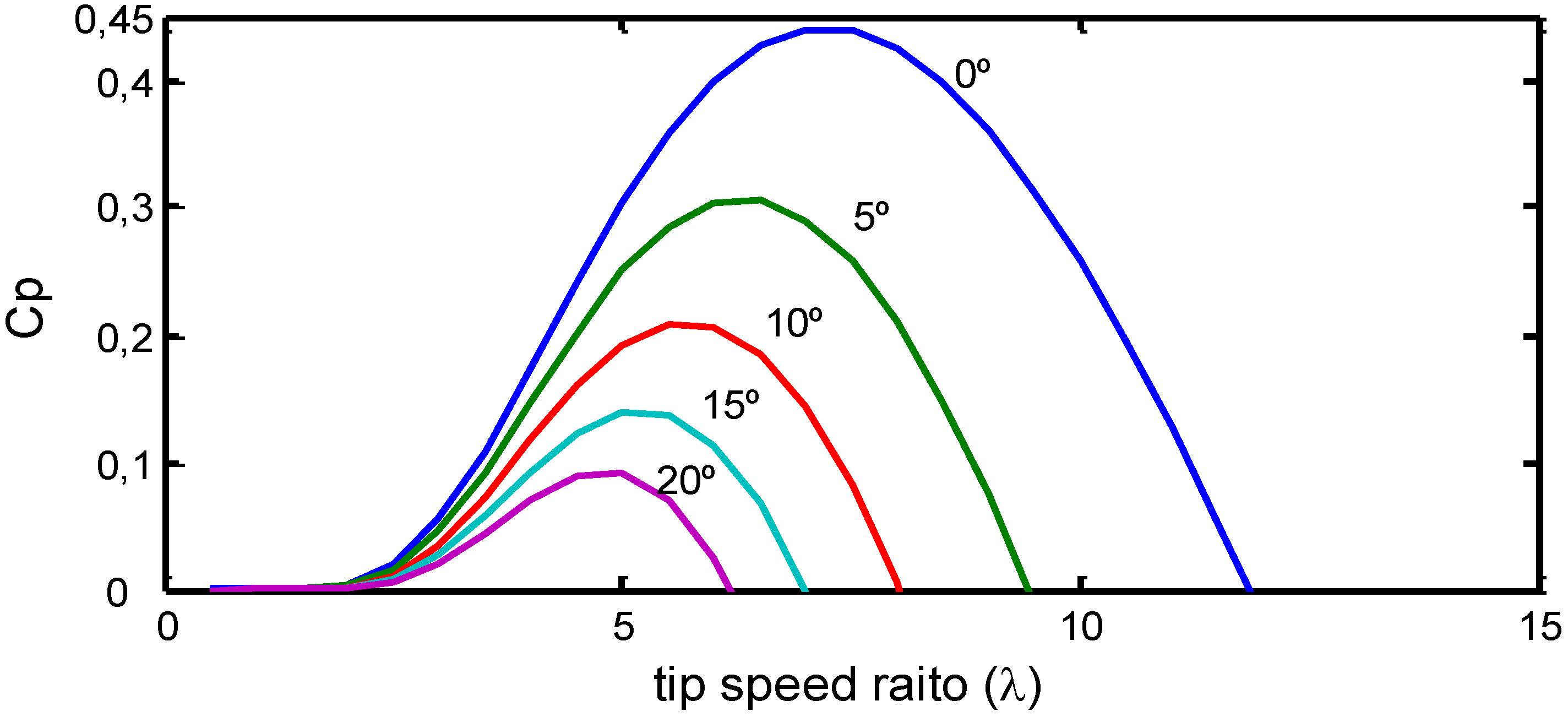
2.1. Aerodynamic Model

The Mechanical power captured from the wind and the mechanical torque developed by the turbine shaft can be calculated using the well-know aerodynamic Equations (1) and (2), at least addressed in [12,13]:
P m = 1 2 A ρ V 3 C p ( λ , β )
T m = P m ω m = 1 2 A ρ V 2 C p ( λ , β ) R λ
where
  • Tm = Mechanical torque (N.m)
  • Pm = Mechanical power (W)
  • A = Swept area by the turbine rotor (m2)
  • R = Turbine rotor radius (m)
  • ρ = Air density (kg/m3)
  • V = Wind speed (m/s)
  • Cp = Power coefficient (or performance coefficient)
  • λ = Tip speed ratio (ωm.R/V)
  • ωm = Angular speed of the wind turbine (rad/s)
  • β = Blade pitch angle (degree)
The power coefficient (Cp) indicates how efficiently the conversion of wind power to rotational mechanical power is performed by the wind turbine. The Betz limit is the maximum theoretic value reached by the power coefficient which is 0.59 for three blades horizontal axis wind turbine (a more complete discussion can be find in [12]). The Cp curves are obtained experimentally by the manufactures following international rules. In more generic analysis, the Equations (3) and (4) can be used to model the dynamics of the Cp. The values of c1–c9 presented in Table 3 were suggested by Slootweg to represent the aerodynamics of modern wind turbines [13].
C p ( λ , β ) = c 1 ( c 2 / λ i c 3 β c 4 β c 5 c 6 ) e c 7 / λ i
λ i = 1 1 λ + c 8 β c 9 β 3 + 1
Table 3. Optimized values of the Cp curve equations presented in [13].
c1c2c3c4c5c6c7c8c9
0.731510.580.0022.1413.218.4–0.02–0.003
The Cp curves were calculated for different tip speed ratio (λ) and different blade pitch angle (β). For better visualization, they are shown in Figure 1. The wind turbines from Enercon have one of the highest values of Cp among the largest manufactures (around 0.50).
Figure 1. Cp curves suggested by Slootweg for dynamic analysis.
Energies 03 00738 g001

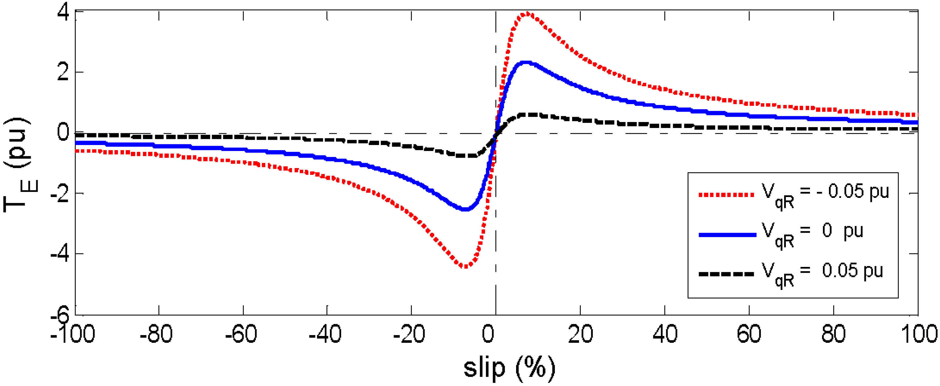
2.2. Electrical Model

The network components are represented by three-phase phasor models. The loads are modeled as constant impedances and transformers are represented by the T circuit. The DFIG is represented by an algebraic-differential model in the dq reference frame, as addressed in [14,15]. The test system shown in Figure 2 is an adaptation of an American Transmission System (WSCC-9), described by M. A. Pai in [16].
Figure 2. Single-line diagram of the test system.
Energies 03 00738 g002
The DFIG is the most widespread configuration for wind turbine generators since the development of highly efficient power electronic converters [6]. The concept is based on two back-to-back voltage source converters connecting the grid and the rotor windings. The stator windings are connected directly to the grid (Figure 3). The parameters used to model the DFIG can be found in [13].
As a generic operation strategy, the grid-side converter (GSC) regulates the active power inject (when the slip s > 0) or absorbed (when s < 0) by the rotor windings depending on the operation point. The rotor-side converter (RSC) regulates the rotor speed and the injection of reactive power to the grid (via rotor windings) to maintain a unitary power factor operation by the wind farm. The schematic diagram of a DFIG is presented in Figure 3.
Figure 3. Schematic diagram of a single DFIG based wind turbine.
Energies 03 00738 g003
The crowbar system used in modern wind turbines is based on a three-phase series resistance controlled by power electronics. The crowbar system is activated during over-current on the rotor windings or/and over-voltage on the DC link. Most of the time, these atypical values appear after a short circuit close to the wind farm. The steps involved during the activation and the deactivation of the crowbar system by the circuit breakers (CB) are summarized:
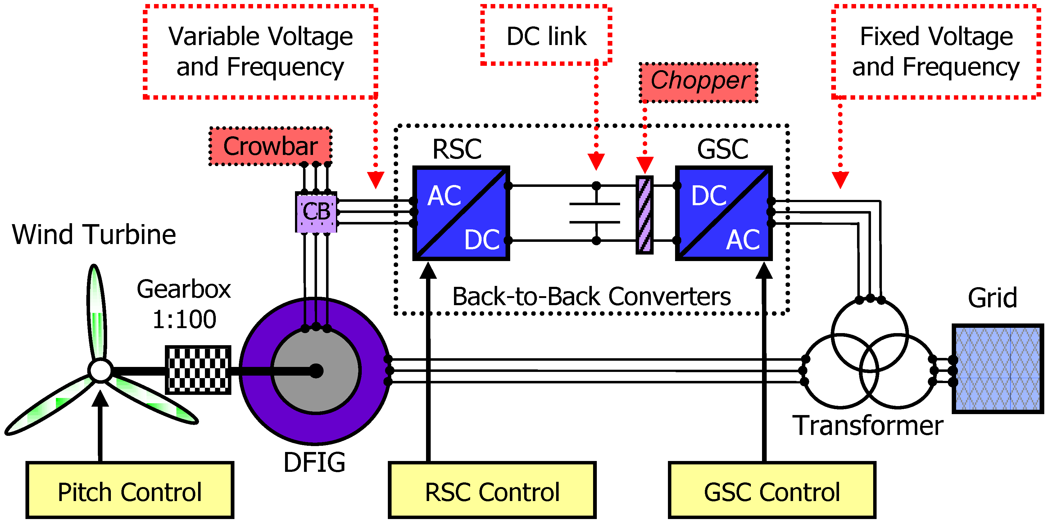
  • Disconnection of the rotor windings from the RSC.
  • Insertion of the three-phase resistance in series to the rotor windings (crowbar system).
  • Disconnection of the crowbar system from the rotor windings.
  • Reconnection of the RSC to the rotor windings.
If the voltage at the DC link or/and the current at the rotor windings are at a normal levels, the operation returns to its normal, however, if not, the activation of the crowbar system can be restarted (the second activation is undesirable). Considering more restrictive grid codes, the use of DC-Chopper system in the DC-link is also recommended to avoid the reinsertion of the crowbar system to enable the reestablishment of the terminal voltage control by the RSC. The DC-Chopper is a thyristor controlled resistance, in which the unbalance of electrical power injection into the power system by the GSC and the electrical power injected into the DC-link by the RSC is dissipated. The strategy combining the crowbar system and the DC-Chopper system were previously studied by the authors in [17]. More details about crowbar systems adopted in modern wind turbines can be found in [12,18].

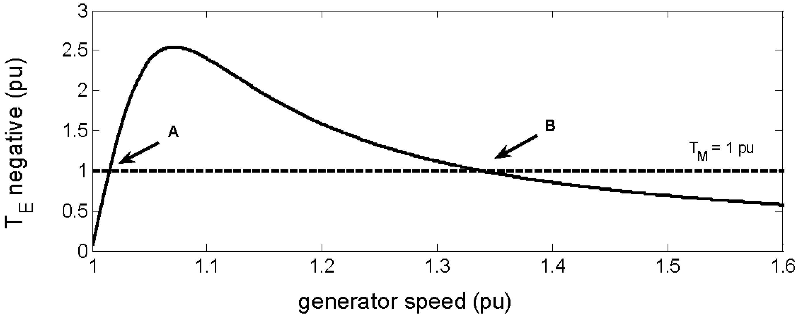
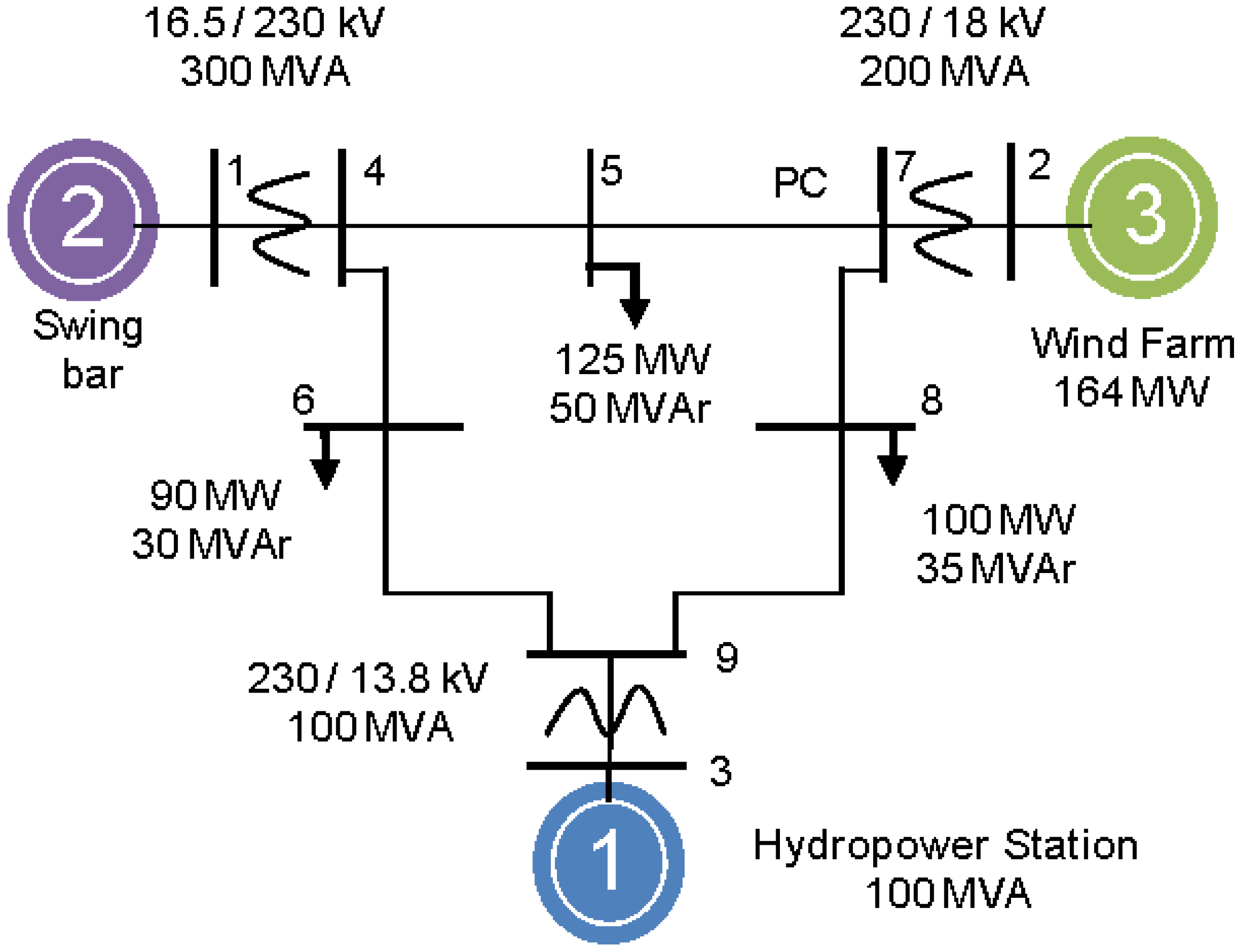
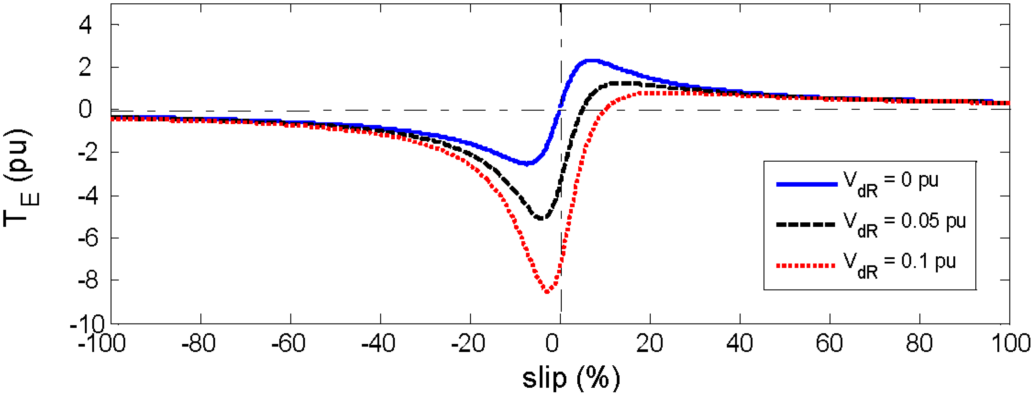
3. The Induction Generators Stability and the Critical Rotor Speed

During short circuits in the grid, the induction generators accelerate due to the reduction of the electrical torque. The large-disturbance stability of induction generators is related to the rotor speed. Samuelsson and Lindahl named this phenomenon as “Speed Stability” in [19], however, the classical theory of power system stability does not address a specific name for this case and it may be covered by the term “Voltage Stability”, as published in [14,20].
The phenomenon of instability of squirrel-cage induction generator (SCIG) can be visualized using the curves of electrical torque and mechanical torque versus generator speed, as show in Figure 4. A fixed value of the mechanical torque is considered in this discussion for simplification only. The mechanical torque and the electrical torque curves have two common points represented by A (stable operation point) and B (unstable operation point or critical rotor speed). The time corresponding to the generator acceleration from point A to point B may be called Critical Fault Clearance Time (Tcrit), it is the maximum duration of a grid fault supported by the generator without losing the stability. The Tcrit is related to the critical rotor speed (ωCR), which in fact indicates the same information, however, in a way to better represent the interest of a specific study.
Figure 4. Negative electrical torque (TE) and mechanical torque (TM) vs. generator speed.
Energies 03 00738 g004
During severe grid faults, the electrical torque drops to zero and the squirrel-cage induction generator starts to accelerate. In case of the fault clearance time (tf) before achieving the critical rotor speed, the electrical torque returns to the operation point C. In this situation, the electrical torque is higher than the mechanical torque. Therefore, the generator speed decelerates and returns to a stable operation in point A, as shown in Figure 5.
Figure 5. Stable operation of squirrel-cage induction generator.
Energies 03 00738 g005
In case of the fault clearance time (tf) after achieving the critical rotor speed, the electrical torque returns to the operation point C. In this situation, the electrical torque is lower than the mechanical torque, therefore, the generator speed accelerates and does not return to a stable operation (Figure 6).
Figure 6. Unstable operation of squirrel-cage induction generator.
Energies 03 00738 g006
The increase of the rotor resistance modifies the electrical torque curve giving different possibilities of the stable operation point A and enlarges the critical rotor speed (point B). The idea of varying the rotor resistance is used for more than a century to vary the speed of wound rotor induction motors [21] in variable speed applications and more recently in variable rotor resistance induction generator (VRRIG) [6,12], as the technology used by Suzlon. The activation of the crowbar system implies that the DFIG become a squirrel-cage induction generator with an extra rotor resistance.
In countries with low wind power penetration the injection of reactive currents during grid faults are not required, for this reason, the crowbar system normally operates during the whole fault period. When more restrictive policies are in need the operation of the crowbar system must be minimized to start the injection of reactive current by the RSC before the fault clearance. The voltage applied to the rotor windings by the control of the RSC also modifies the electromagnetic torque curve and enlarges the critical rotor speed (ωCR) in a more efficiently way than the limited action of the crowbar system.
In Figure 7, the complete electromagnetic torque curve versus the slip of a wound rotor induction machine is shown for different values of the direct axis component of the voltage applied to the rotor windings. When the applied value is enlarged, the maximum electromagnetic torque for generator operation (negative TE) is also enlarged, however, the maximum torque for motor operation (positive TE) is diminished.
In Figure 8, the complete electromagnetic torque curve versus the slip of a wound rotor induction machine is shown for different values of the quadrature axis component of the voltage applied to the rotor windings. When the applied value is enlarging in the negative direction, the maximum electromagnetic torque for generator operation (negative TE) and for motor operation (positive TE) is enlarged. The maximum torque for generator and for motor operation is diminished when the applied voltage is enlarging in the positive direction.
Figure 7. Electromagnetic torque curve vs. slip of wound rotor induction machine for different values of VdR.
Energies 03 00738 g007
Figure 8. Electromagnetic torque curve vs. slip of wound rotor induction machine for different values of VqR.
Energies 03 00738 g008
From Figure 7 and Figure 8, we can conclude that the control of the RSC can modify the TE during the short circuit (or immediately after its elimination, depends on the grid requirements) to a value that enlarges the critical rotor speed and forces TE to be equal (or higher) to TM much more faster than in the case of the SCIG despite the higher rotor speed operation of the DFIG.

4. The Dynamic Analysis of the Crowbar System Actuation during Grid Faults

The main objective of this article is to clarify the influence of the crowbar system on the dynamic performance of DFIG based wind turbines. The influence of the crowbar resistance value and the crowbar operation time are analyzed. The analyses are performed during a 150 ms fault at the bus B5 and at the bus B7 of the test system shown in Figure 2.

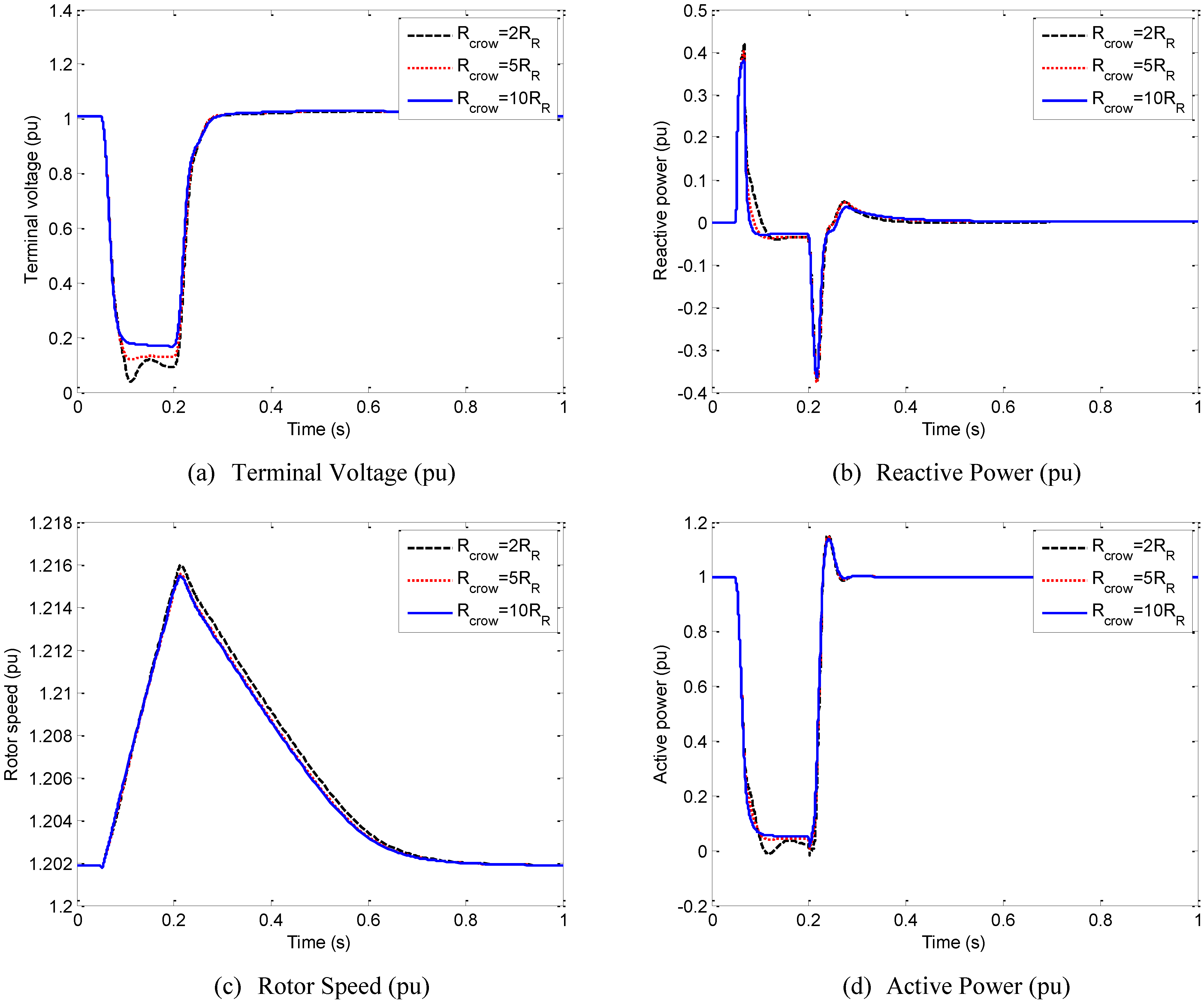
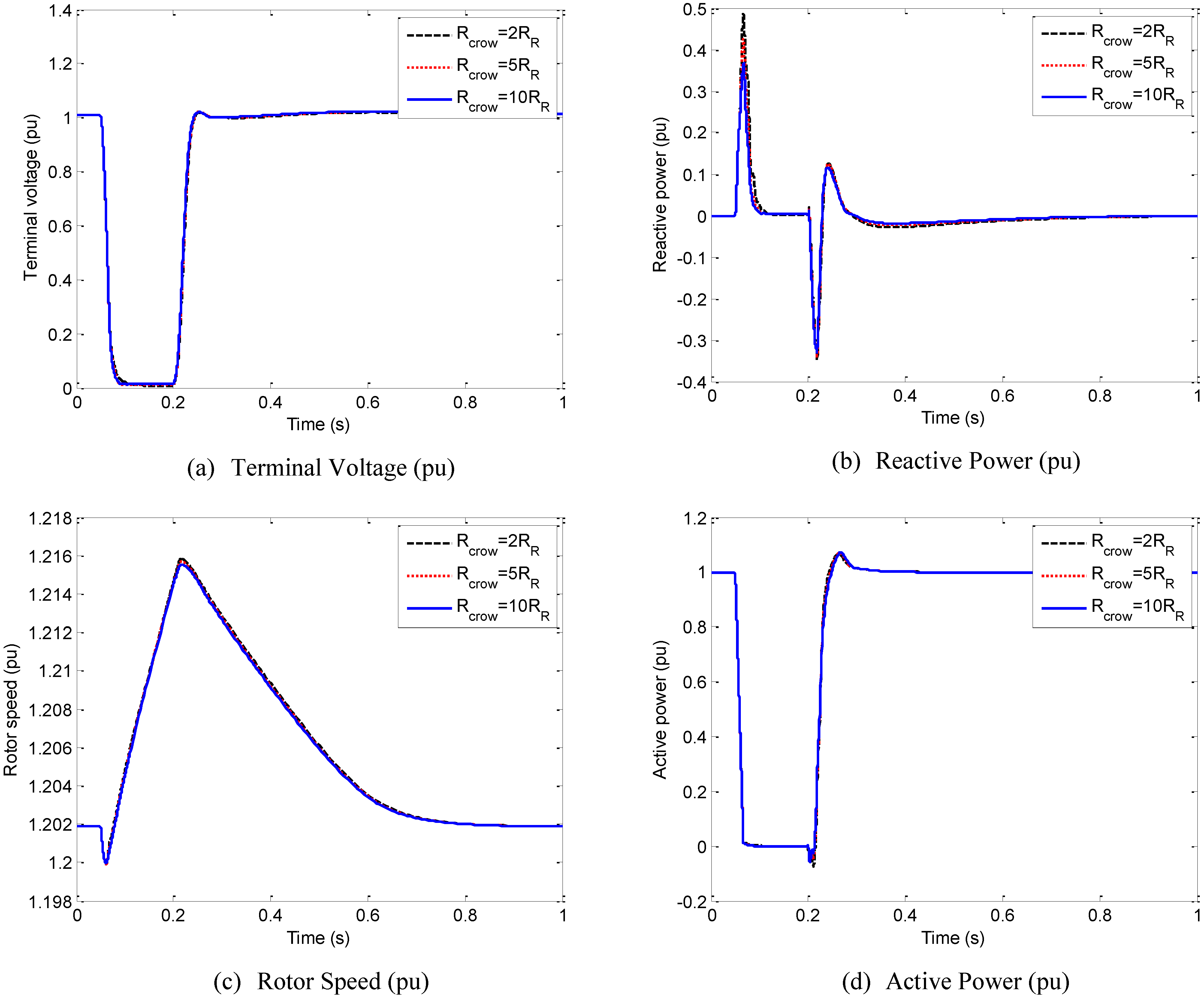
4.1. Influence of the Crowbar Resistance Value (Rcrow)

The control strategy adopted during fault for this analyses is described: the RSC is blocked and the crowbar system is activated; the GSC controls the DC-link voltage; the RSC is restarted and crowbar system is removed after the fault elimination. Different Rcrow are analyzed (2, 5 and 10 times the original rotor resistance RR). This is the most common operation mode during faults for countries with no reactive current injection requirement.
The terminal voltage shown in Figure 9a is higher during the fault when the Rcrow equal to 10.RR is used. In Figure 9b, the lower consumption of reactive power during the fault can explain the lower value of rotor speed shown in Figure 9c. Considering the stability of the machine the desired rotor speed should be as closer as possible to the normal operation speed in order to avoid the critical rotor speed, as described in Section 3. The active power injected by the DFIG is also increased for high values of the Rcrow, as shown in Figure 9d.
Figure 9. Dynamic analysis of the DFIG for different crowbar resistance value during a fault eliminated in 150 ms at B5.
Energies 03 00738 g009
Figure 10 shows the wind farm performances during a fault close to its terminal at the bus B7, the values of the Rcrow do not contribute in a different way from each other. However, the crowbar system is still important to guarantee a fast reconnection of the RSC to reestablish normal operation and to protect the power electronics of the RSC from damage. If the fault is not eliminated before the critical rotor speed is achieved the rotor may accelerate and loose the stability. The period of time that the wind turbines must remain connected to the network depends on the TSO requirements of the region and of the country (for some countries these times can be found in [8,10,22]).
Figure 10. Dynamic analysis of the DFIG for different crowbar resistance value during a fault eliminated in 150 ms at B7.
Energies 03 00738 g010

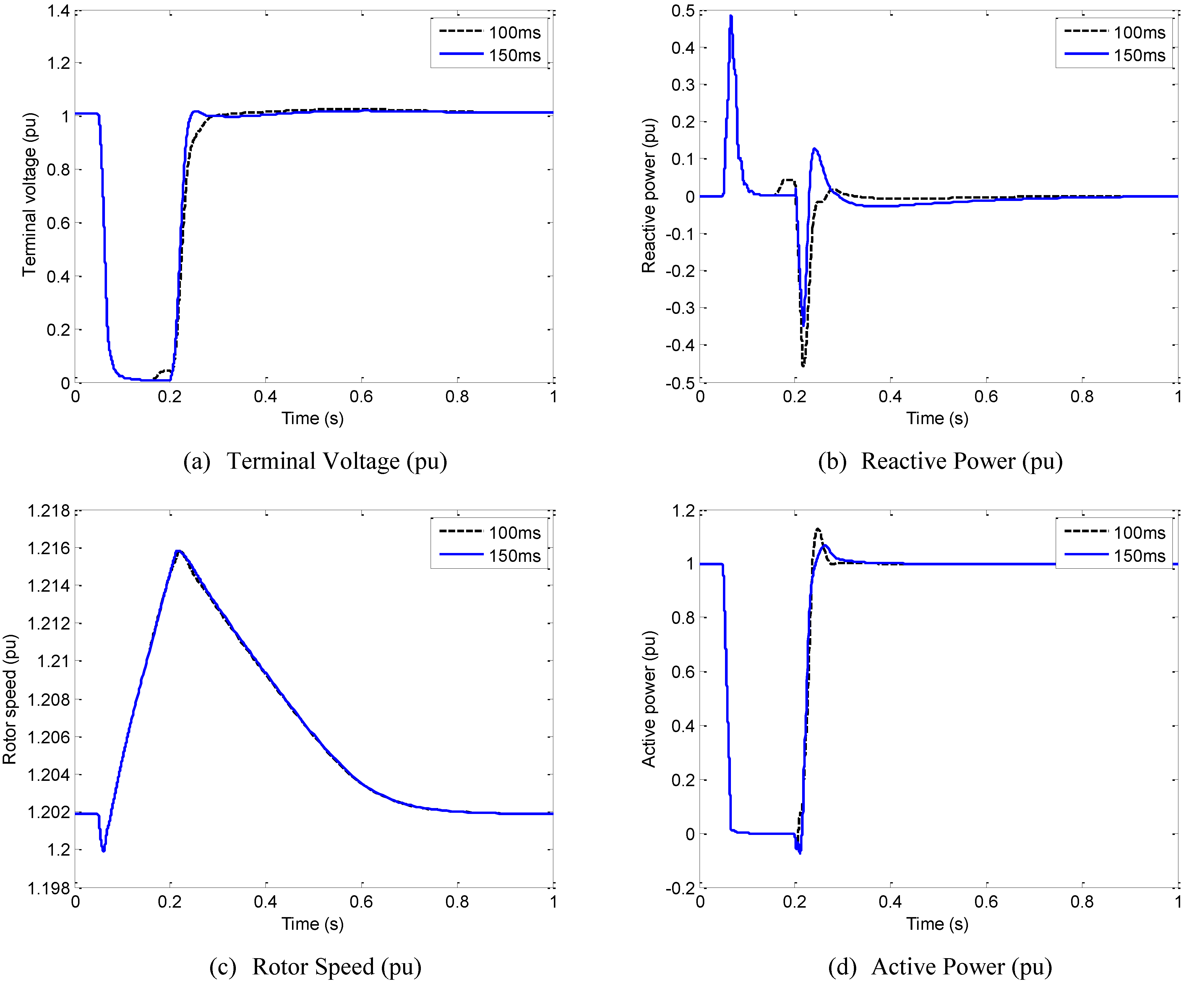
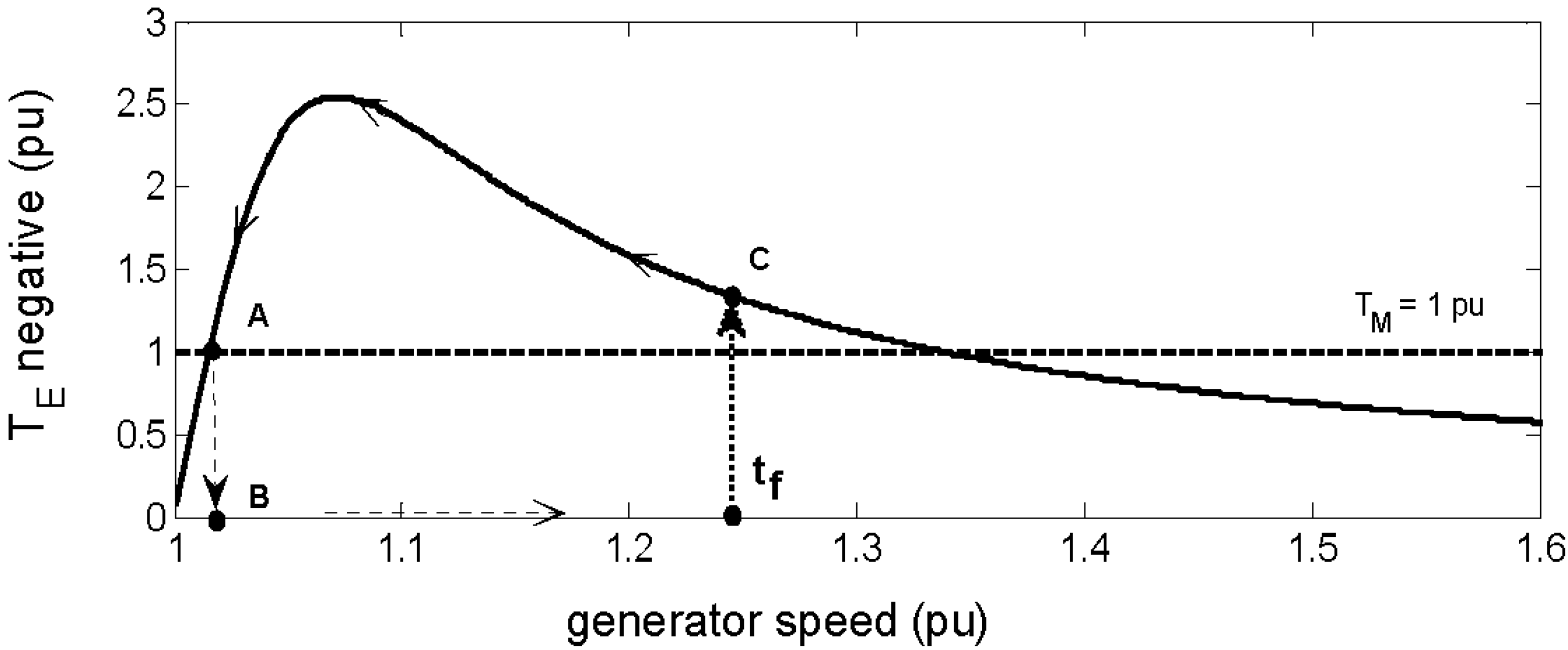
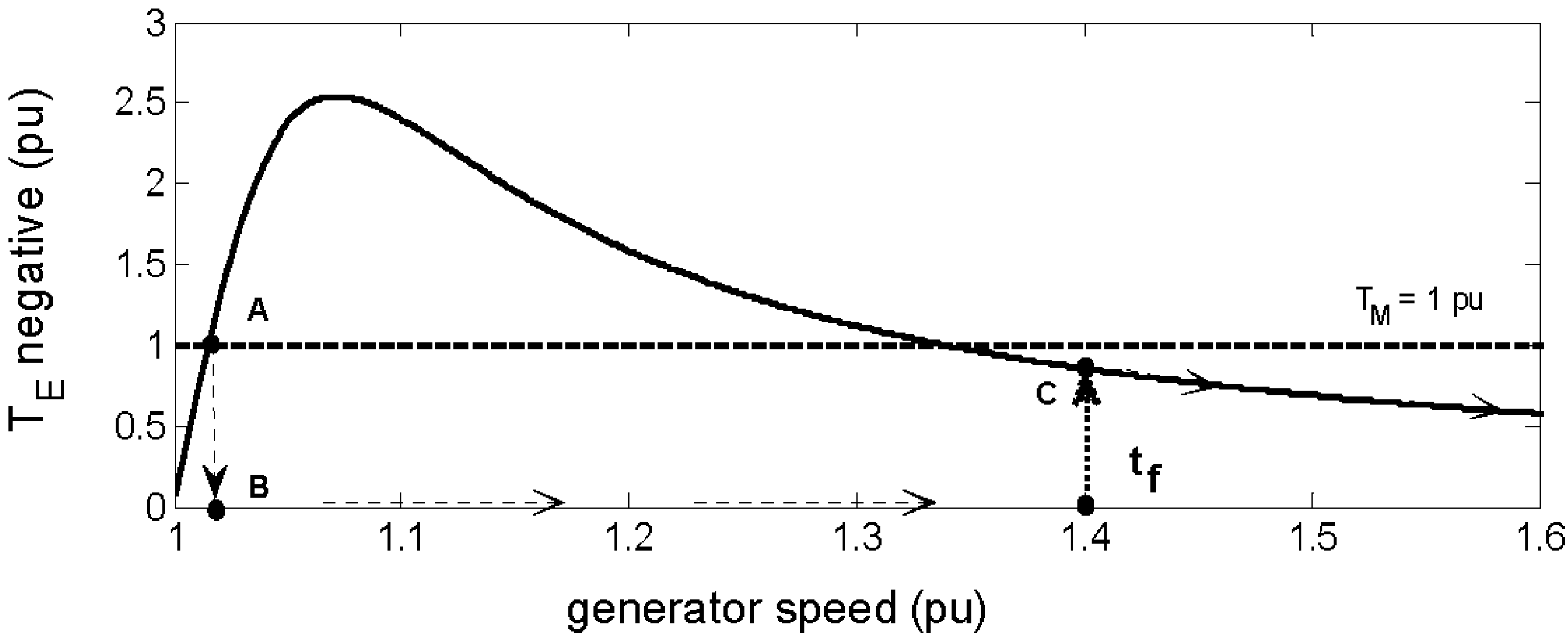
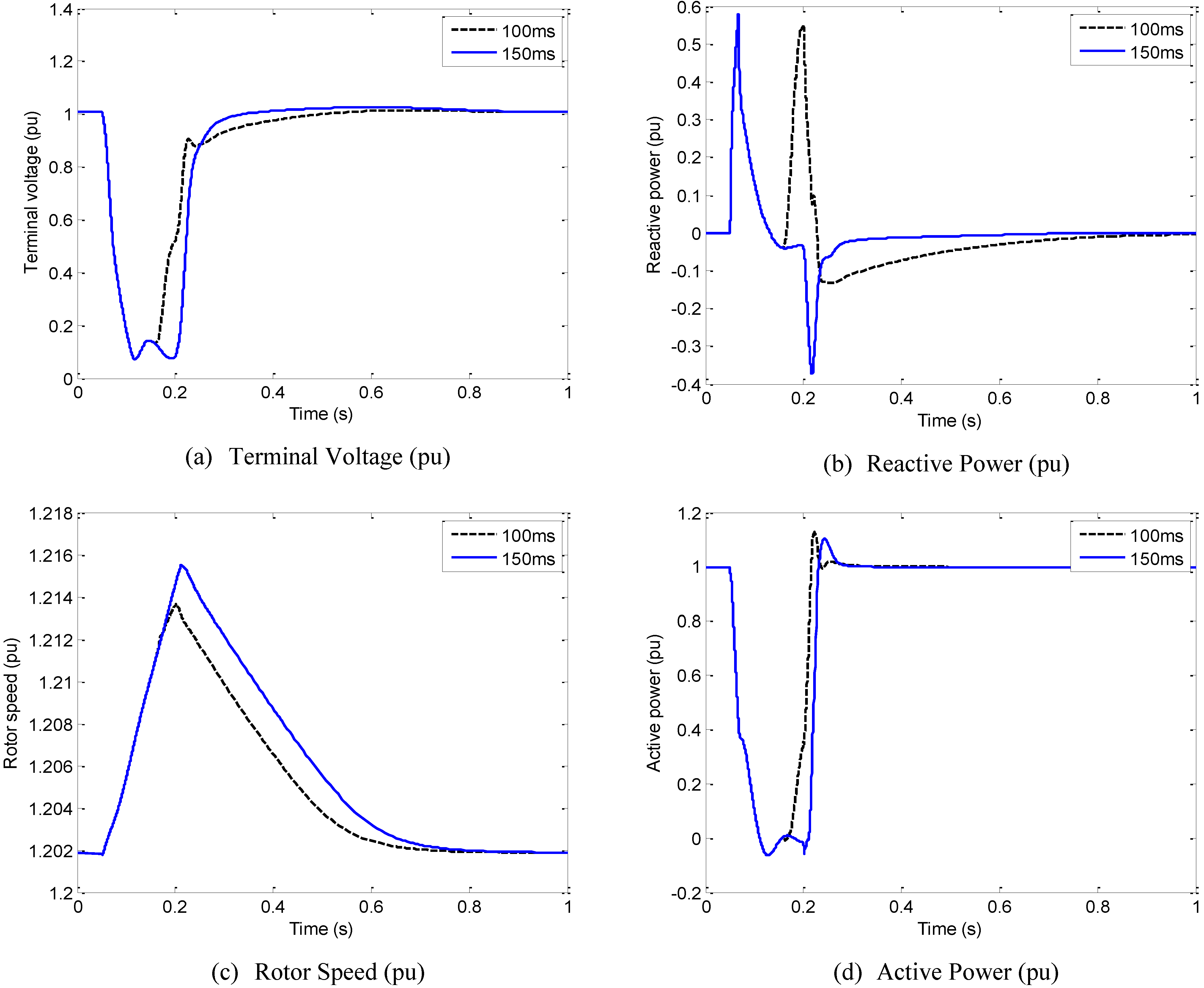
4.2. Influence of the Crowbar System Operation Time

In countries such as Spain and Germany, the operation mode during fault is more restrictive and the reactive current injection during the fault is required. By consequence, the crowbar system must actuate for a short time in order to enable the reactive current injection by the RSC via rotor windings.
In Figure 11, the analysis of two different operation times of the crowbar system during a fault at the bus B5 is presented. The DC-Chopper is also enabled to maintain the DC-link voltage during the crowbar system actuation and the Rcrow is considered equal to 2.RR for the following analysis.
Figure 11. Dynamic analysis of the DFIG for different crowbar operation time during a fault at B5 eliminated in 150 ms.
Energies 03 00738 g011
Figure 11a shows that when the crowbar operation time is equal to 100 ms, the terminal voltage increases before the elimination of the fault. As shown in Figure 11b, the injection of reactive power (positive values) during the fault by the RSC contributes to increase the terminal voltage. In Figure 11c, the rotor speed achieved by 100 ms operation time is lower than for 150 ms and the rotor speed operates closer to its normal speed avoiding the operation close to the critical rotor speed. The active power injected by the DFIG is close to zero for both operation times since the terminal voltage is almost zero, as shown in Figure 11d.
In Figure 12, the analysis of two different crowbar system operation time for a more severe fault close to the wind farm at the bus B7 is presented.
Figure 12. Dynamic analysis of the DFIG for different crowbar operation time during a fault at B7 eliminated in 150 ms.
Energies 03 00738 g012
Figure 12a shows that when the crowbar operation time is equal to 100 ms, the terminal voltage increases before the elimination of the fault. As shown in Figure 12b, the injection of reactive power (positive values) during the fault by the RSC contributes to increase the terminal voltage. Figure 12c shows the rotor speed achieved by the 100 ms operation time does not have any significance on the performance due to the low reactive power injection in very low terminal voltage. The active power injected by the DFIG is close to zero for both operation times since the terminal voltage is very small, as shown in Figure 12d. The most advantage of the use of a shorter operation time is the possibility of reactive power injection during the fault, although, for more severe faults the injection is limited.

5. Conclusions

This article presents the dynamic analysis of a DFIG-based wind farm connected to a test system. The dynamic model of the aerodynamics of the wind turbine and the electrical model were described in Section 2. A short revision of the instability phenomenon of induction generators was presented in Section 3. Dynamic simulation to verify the influence of the crowbar resistance value and its operation time were performed and are shown in Section 4.
Based on the results, when the wind turbines must keep connected during faults, the crowbar resistance value should be high enough to guarantee lower reactive power consumption. However, when the fault occurs close to the wind farm, the influence of the crowbar resistance is lower.
For more strict grid codes (such as from Germany and Spain) where the injection of reactive power is mandatory, the operation time of the crowbar system must be reduced to enable a fast restart of the RSC controlling the terminal voltage at the wind farm terminals.

Acknowledgements

The authors gratefully acknowledge the financial support from the Brazilian government via FAPESP (State of São Paulo Research Foundation), CNPq (National Counsel of Technological and Scientific Development) and CAPES (“Coordenação de Aperfeiçoamento de Pessoal de Nível Superior”, in Portuguese) as well as from Germany via DAAD (German Academic Exchange Service) to develop this research.

References

  1. European Wind Energy Association. Wind Energy—The Facts: A Guide To The Technology, Economics And Future Of Wind Power; Earthscan Publications: London, UK, March 2009. [Google Scholar]
  2. Global Wind Energy Council. Global Wind 2008 Report. Available online: http://www.gwec.net/fileadmin/documents/Global%20Wind%202008%20Report.pdf (accessed on 10 December 2009).
  3. ANEEL. Brazilian Information Data of Power Generation. Available online: http://www.aneel.gov.br/aplicacoes/capacidadebrasil/capacidadebrasil.asp (accessed on 10 December 2009).
  4. Emerging Energy Research. Global Wind Turbine Supply Market Share Update. Available online: http://www.environmentalleader.com/wp-content/uploads/2009/03/wind-turbine-market-share.jpg (accessed on 10 December 2009).
  5. Molly, J.P. Status der Windenergienutzung in Deutschland—Stand 31.12.2008 (in German). DEWI GmbH. Available online: http://www.wind-energie.de (accessed on 10 December 2009).
  6. Li, H.; Chen, Z. Overview of Different Wind Generator Systems and their Comparisons. IET Renew. Power Generat. 2008, 2, 123–138. [Google Scholar] [CrossRef]
  7. Morren, J.; de Haan, S.W.H. Ridethrough of Wind Turbines with Doubly-fed Induction Generator during a Voltage Dip. IEEE Trans. Energy Convers. 2005, 20, 435–441. [Google Scholar] [CrossRef]
  8. Ullah, N.R.; Thiringer, T.; Karlsson, D. Voltage and Transient Stability Support by Wind Farms Complying With the E.ON Netz Grid Code. IEEE Trans. Power System 2007, 22, 1647–1656. [Google Scholar] [CrossRef]
  9. Grid Code: High and Extra High Voltage. E.ON Netz GmbH Tech. Rep., Status: 1. Available online: http://www.eon-netz.com (accessed on 10 December 2009).
  10. Requisitos de Respuesta frente a Huecos de Tensión de las Instalaciones Eólicas. BOE no. 254. 2006, pp. 37017–37019. (in Spanish). Available online: http://www.ree.es/operacion/pdf/po/PO_resol_12.3_Respuesta_huecos_eolica.pdf (accessed on 10 December 2009).
  11. Grilo, A.P.; Mota, A.A.; Mota, L.T.M.; Freitas, W. An Analytical Method for Analysis of Large-Disturbance Stability of Induction Generators. IEEE Trans. Power Syst. 2007, 22, 1861–1869. [Google Scholar] [CrossRef]
  12. Akhmatov, V. Analysis of Dynamic Behaviour of Electric Power Systems with Large Amount of Wind Power. Ph.D. Thesis, Technical University of Denmark, Denmark, 2003. Available online: http://www.dtu.dk/upload/institutter/_oersted/eltek/research/00-05/05-va-thesis.pdf (accessed on 10 December 2009). [Google Scholar]
  13. Slootweg, J.G.; Polinder, H.; Kling, W.L. Representing Wind Turbine Electrical Generating Systems in Fundamental Frequency Simulations. IEEE Trans. Energy Conv. 2003, 18, 516–524. [Google Scholar] [CrossRef]
  14. Kundur, P. Power System Stability and Control; McGraw-Hill: New York, NY, USA, 1994. [Google Scholar]
  15. SimPower Systems—User's Guide: Version 5. Math Works. Available online: http://www.mathworks.com/access/helpdesk_r13/help/pdf_doc/physmod/powersys/powersys.pdf (accessed on 10 December 2009).
  16. Sauer, P.W.; Pai, M.A. Power System Dynamics and Stability; Prentice Hall: Upper Saddle River, NJ, USA, 1998. [Google Scholar]
  17. Salles, M.B.C.; Cardoso, J.R.; Grilo, A.P.; Rahmann, C.; Hameyer, K. Control Strategies of Doubly Fed Induction Generators to Support Grid Voltage. In Proceedings of IEEE International Electric Machines and Drives Conference—IEMDC'09, Miami, FL, USA, May 2009.
  18. Seman, S.; Niiranen, J.; Arkkio, A. Ride-Through Analysis of Doubly Fed Induction Wind-Power Generator Under Unsymmetrical Network Disturbance. IEEE Trans. Power Syst. 2006, 21, 1782–1789. [Google Scholar] [CrossRef]
  19. Samuelsson, O.; Lindahl, S. On Speed Stability. IEEE Trans. Power Syst. 2005, 20, 1179–1180. [Google Scholar] [CrossRef]
  20. Kundur, P.; Paserba, J.; Ajjarapu, V.; Andersson, G.; Bose, A.; Canizares, C.; Hatziargyriou, N.; Hill, D.; Stankovic, A.; Taylor, C.; Van Cutsem, T.; Vittal, V. Definition and Classification of Power System Stability IEEE/CIGRE Joint Task Force on Stability Terms and Definitions. IEEE Trans. Power Syst. 2004, 19, 1387–1401. [Google Scholar] [CrossRef]
  21. Storer, N.W. Three-Wire System for Variable Speed Motor Work. Transactions of the AIEE 1902, 20, 127–133. [Google Scholar]
  22. Submódulo 3.6 – Requisitos Técnicos Mínimos para a Conexão à Rede Básica. Operador Nacional do Sistema (ONS), Resolução Normativa 372/09. Agosto 2009. (in Portuguese)

