
Exploring Motion Stability of a Novel Semi-Submersible Platform for Offshore Wind Turbines
1
Department of Mechanical Engineering, Hunan Institute of Engineering, Xiangtan 411104, China
2
Hunan Province Engineering Laboratory of Wind Power Operation, Maintenance and Testing Technology, Xiangtan 411104, China
*
Author to whom correspondence should be addressed.
Energies 2024, 17(10), 2313; https://doi.org/10.3390/en17102313
Submission received: 14 March 2024
/
Revised: 1 May 2024
/
Accepted: 8 May 2024
/
Published: 10 May 2024
(This article belongs to the Topic Advances in Power Science and Technology)
Abstract
:The stability of offshore floating wind turbine foundation platforms is a fundamental requirement for the efficiency and safety of wind power generation systems. This paper proposes a novel small-diameter float-type semi-submersible platform to improve system stability. To evaluate the superior motion stability of the proposed floating platform, a comprehensive frequency–domain response analysis and experimental study were conducted in comparison with the OC4-DeepCwind platform developed by the National Renewable Energy Laboratory (NREL). The respective comparison of the frequency–domain response analysis and the experimental results demonstrated that the proposed floating wind turbine platform shows better hydrodynamic characteristics and resonance avoidance capability. This not only reduces the Response Amplitude Operators (RAOs), but also enhances the system stability, namely, effectively avoiding the regions of concentrated wave loading and low-frequency ranges. Furthermore, the proposed small-diameter semi-submersible platform has the potential to reduce manufacturing costs, providing valuable insights for the manufacturing of offshore floating wind turbine systems.
1. Introduction
In recent years, offshore floating wind energy technology has garnered increasing interest due to the richer and more stable wind resources available in deep-sea areas compared to coastal regions [1]. However, harnessing wind energy in deep-sea locations poses greater challenges compared to exploiting nearshore wind energy resources. Among the numerous challenges, one of the most critical issues is how to mitigate wave loads on offshore floating wind turbines (OFWTs) to enhance their motion stability [2].
Efforts have been made in recent years to improve the motion stability of OFWTs. For instance, improvements have been pursued through structural design modifications aimed at reducing platform motion and enhancing stability. Lemmer et al. [3] optimized design parameters such as column spacing, diameter, and height based on the OC4DeepCwind platform, demonstrating that the optimized structure effectively resists structural fatigue and ultimate loads. Zhang et al. [4] proposed a novel offshore wind turbine platform design and optimization method, introducing a tilted-column fully submerged OFWT platform with superior hydrodynamic performance and economic feasibility. Zhou et al. [5] improved the original OC4 model by integrating optimized multi-segment mooring lines and tilted columns, resulting in a new model capable of effectively reducing the heave and pitch motions of semi-submersible floating wind power platforms. Scicluna [6] developed a self-aligning single-point mooring buoy and conducted a stability analysis, revealing greater stability along the transverse axis compared to the pitch axis, meeting all requirements stipulated by DNV regulations. Rezanejad et al. [7] conducted experimental research on the hydrodynamic performance of a novel dual-chamber floating oscillating water column device, providing valuable insights for the design of such systems.
In addition, considerable scholarly efforts have been devoted to studying the hydrodynamic characteristics of these platforms. Chen et al. [8] developed a numerical model that fully couples air–water hydrodynamic analysis to evaluate OFWTs, offering precise forecasts of platform motions and dynamic loads critical for structural integrity assessments. Tabeshpour et al. [9] established a three-dimensional boundary element model of the Amirkabir platform using the boundary element method for hydrodynamic analysis, accurately obtaining RAOs. Yang et al. [10] formulated an aero-hydro-servo-elastic coupling framework for OFWT analysis, capturing the intricate interactions among aerodynamics, fluid dynamics, and structural components, and thus providing a nuanced representation of system dynamic behavior. Gao et al. [11,12,13], employing the OpenFOAM model, investigated the transient gap resonance between two solids induced by varying focusing wave amplitudes and spectral peak periods, yielding insights into mitigating vibration and motion response in such floating body systems. Zou et al. [14] introduced a novel short-term prediction method for OFWTs using the Kriging-MOGA algorithm, emphasizing the substantial influence of aerodynamic loads on floating wind turbine platform stability. Bashetty and Ozcelik [15] conducted a comprehensive review of OFWT dynamics, emphasizing the diverse challenges associated with operational aspects and underscoring the necessity for precise modeling and simulation techniques to ensure the safety and efficacy of these systems. Deng et al. [16] proposed a novel method employing neural networks for predicting semi-submersible platform motions, furnishing an accurate and efficient tool for platform dynamic evaluation. Rezanejad et al. [17], utilizing internally coupled tools to integrate far-field nonlinear waves, applied High-Order Spectral (HOS) methods to enhance the prediction of low-frequency motion responses of OFWTs.
Continuing from the aforementioned work, this paper presents a novel semi-submersible floating platform designed to support OFWTs, with an iterative optimization of its initial parameters to meet desired stability requirements. To facilitate this study, a hydrodynamic numerical model of the proposed semi-submersible floating wind turbine platform was first established, and its hydrodynamic performance, dynamic response, and wind–wave experimental performance were studied using ANSYS AQWA 2022 R2. Subsequently, scale models of both the proposed platform and the OC4-DeepCwind platform developed by the NREL were fabricated and tested in a multifunctional water tank. The comparison between these two platforms revealed that the proposed floating wind turbine platform has a superior natural period and is able to effectively avoid energy concentration areas and low-frequency ranges of waves, thereby reducing platform wave loads and actual motion response RAOs, and showing better hydrodynamic performance and stability. The specific computational theory will be introduced in Section 2. Section 3 will detail the main parameters of the platform model and mooring system. Section 4 will conduct the hydrodynamic analysis and the RAO comparisons for the two models, followed by Section 5, which will introduce the experimental equipment and validate the simulations through scaled model testing. Finally, a summary is given in Section 6.
2. Mathematical Theory
To provide a clear exposition of the research approach, Figure 1 displays a flowchart that depicts the study’s content and outlined methodology. The diagram encompasses the investigation of numerical models, the theoretical framework utilized, and the data derived from hydrodynamic calculations. Finally, a comparative and validating analysis of the two models is conducted through experimental methods.
2.1. Morrison Equation
For small-diameter components (where the ratio of component diameter to wavelength satisfies ≤ 0.15) [18], their presence has minimal impact on the surrounding flow field. When calculating wave forces, the Morrison equation method is employed. According to this method, wave forces can be divided into two parts: one part is the velocity force generated by the undisturbed velocity field, and the other part is the acceleration force generated by the wave acceleration field. For floating foundations, considering the motion of the foundation, the wave load on a unit height column can be expressed as follows:
In the equation, represents the inertial force acting on the unit height column; denotes the velocity force exerted on the unit height column; stands for the diameter of the column; represents the unit height; signifies the density of water; denotes the relative velocity between the water particle and the floating foundation; represents the velocity of the water particle; and and , respectively, represent the added mass coefficient and the drag coefficient. The value of , is typically set to 1.0.
2.2. Potential Flow Theory
For large-diameter components [18], the presence of structures will affect the surrounding flow field. In the theoretical calculation of wave loads, three-dimensional potential flow theory is commonly employed. This theory assumes that the water is an incompressible, inviscid, and irrotational ideal fluid, where waves are considered as potential motions, and linearized free surface boundary conditions are used for the solution. When the floating platform moves in still water, the first-order velocity potential in the flow field satisfies the Laplace equation:
Here, is the Laplace operator, representing the sum of the second-order spatial derivatives of the velocity potential. By solving this equation, the distribution of velocity potential in the flow field can be obtained, and thereby we can calculate the wave loads on the floating platform.
The first-order linear wave force is obtained through computation.
In the equation, represents the wave load generated by incident potential; denotes the diffraction force; signifies the radiation force; stands for the wave frequency; denotes the normal direction; represents the wetted surface area; stands for the incident potential; stands for the diffracted potential; stands for the density of water; stands for the direction factors; and denote the imaginary and real parts of the incident potential, respectively; and and represent the added mass coefficient and radiation damping coefficient, where , represents the degrees of freedom of the structure.
2.3. Hydrodynamic Theory
Based on the potential flow theory approach, considering the Bernoulli equation and the velocity potential equation, hydrodynamics are calculated based on the distribution of the fluid velocity field and pressure field. Reducing the waterline area will alter the hydrodynamic characteristics of the floating body. The specific statement is as follows:
Here, represents the density of the fluid, is the velocity field on the floating body, denotes the velocity field of the fluid flow, and represents the wetted surface area.
3. The Proposed Floating Platform
3.1. Numerical Model
The proposed floating platform features a distinctive inward concave design at the waterline of its three external columns, setting it apart from the conventional OC4-DeepCwind platform. This unique design leads to a noteworthy reduction in the waterplane area of the proposed floating platform. Consequently, the platform, in theory, would be subjected to decreased wave loads. For this reason, the proposed design would significantly benefit the motion stability of the OFWTs in their practical application. For ease of understanding, the conceptual design of the proposed floating platform and the OC4-DeepCwind platform are shown in Figure 2.
To enable the study of the proposed platform and the comparison with the OC4-DeepCwind platform, numerical models of both platforms were developed in ANSYS AQWA. By referencing the pertinent parameters of the OC4-DeepCwind platform [19], the initial dimensions of the proposed floating platform and the OFWT supported by it were determined. The structures of the platforms are depicted in Figure 3, and their numerical parameters are listed in Table 1.
3.2. Mooring System
The mooring system of the proposed platform is composed of three steel catenary mooring chains and their associated cable ducts. The cable ducts are designed to be located 14 m below the waterline on the large-diameter hanging cylinder at the bottom of the construction. The three mooring anchors are located in the seabed, and the cable duct and anchor point are connected to both ends of the catenary line. This type of semi-submersible platform has a large self-weight, providing self-stability. Figure 4 shows the schematic diagram of the mooring system, and Table 2 provides the parameters of the mooring chains.
4. Frequency–Domain Analysis
In this section, the hydrodynamic performances of the OFWTs that are supported by the proposed floating platform and the OC4-DeepCwind platform are studied numerically with the aid of ANSYS AQWA. During the numerical calculations, by following a consistency check, the whole computational domain is meshed by 12,000 elements, about 8000 of which are diffraction elements. In the numerical models, the mass of the wind turbine is simplified to a point force acting on the top surface of the platform. The structural meshing is shown in Figure 5.
In this study, both the near-field and far-field methods described in [20,21,22] were applied to calculate the second-order wave forces for validating the effectiveness of the meshing results and the reliability of the hydrodynamic model. The second-order mean drift forces in the surge direction obtained for the OFWTs supported by the two types of floating platforms are shown in Figure 6.
From Figure 6, it can be seen that the results of the average drift force in the surge direction obtained using the near-field and far-field methods are consistent in both trend and magnitude. Therefore, it can be concluded that the model meshing method meets the hydrodynamic calculation accuracy requirements very well.
4.1. Hydrodynamic Viscous Damping
The OFWT supported by the proposed floating platform will be deployed in an offshore wind farm where the water is 200 m deep and the density of the seawater is 1025 kg/m3. The incident wave period ranges from 2.6 to 50 s (i.e., 2.147 to 0.126 rad/s). Based on the potential flow theory for the hydrodynamic performance analysis of OFWTs [23,24,25], the issue of the overestimated hydrodynamic response of the OFWT is addressed by introducing additional viscous damping as a corrective measure in the calculation. The additional viscous damping effectively mitigates the overestimation, thereby leading to more accurate and reliable predictions.
Assuming the critical damping coefficient of the system in a particular Degree Of Freedom (DOF) is , it can be mathematically expressed as
where is the moment of inertia, is the added mass of the platform in the DOF of interest, and represents the hydrostatic restoring coefficient of the platform.
Take 5% of in every DOF as the additional viscous damping in the corresponding direction to assess the hydrodynamic performance of the OFWT. The estimated results of the additional viscous damping for the OFWT supported by the two types of floating platforms are listed in Table 3.
To verify the effect of the additional viscous damping on motion stability, the RAOs of the OFWT in the heave and roll directions were calculated before and after considering additional viscous damping, respectively. The results obtained when the wave incident angle is 0° are shown in Figure 7. Figure 7a depicts the calculated RAOs of the OFWT when it is supported by the proposed floating platform, while Figure 7b shows the RAOs of the OFWT when it is supported by the OC4-DeepCwind platform.
From Figure 7, it can be seen that regardless of the supporting platform, the hydrodynamic response of the OFWT is significantly biased before additional viscous damping is considered. By contrast, after considering additional viscous damping, the RAOs of the OFWT in both the heave and roll directions are diminished to varying extents across a wide range of wave periods. Therefore, it is imperative to consider additional viscous damping when employing ANSYS AQWA to evaluate the hydrodynamic responses of OFWTs.
4.2. Hydrodynamic Response
The RAO, i.e., the ratio of the motion amplitude of the structure in each DOF to the amplitude of sea waves, indicates the hydrodynamic response characteristics of a floating structure in waves. To investigate the hydrodynamic response of the OFWT under various wave conditions when it is supported by the proposed floating platform and to demonstrate the superiority of the proposed platform over the OC4-DeepCwind platform in ensuring the safety and reliability of the OFWT in extreme weather conditions, the RAOs of the OFWT supported by the proposed platform and the OC4-DeepCwind platform, respectively, are calculated with the incident waves approaching from various directions.
Firstly, Figure 8 shows the RAOs of the OFWT in all six DOFs when the OFWT is subjected to regular waves characterized by different wave periods and incident angles.
From Figure 8, it can be seen that, as expected, the dynamic response of the OFWT in the heave direction is insensitive to the change in the incident wave angle. In other words, the RAOs of the OFWT at the corresponding wave periods remain unchanged when the incident wave angle changes. By contrast, the RAOs of the OFWT at the corresponding wave periods in the other five DOFs show significant change as soon as the incident wave angle changes. This suggests that the hydrodynamic responses of the OFWT in the other five DOFs are sensitive to the change in the approaching direction of incident waves.
To demonstrate the superiority of the proposed platform over the conventional OC4-DeepCwind platform in ensuring the safety and reliability of the OFWT in extreme weather conditions, the RAOs of the OFWT supported by the proposed platform and the OC4-DeepCwind platform, respectively, are compared in this study. The comparison results in the heave and pitch directions are illustrated in Figure 9. Herein, the RAOs of the OFWT in the heave and pitch directions are of interest in the comparison because the safety and power generation efficiency of the OFWT can be significantly affected by the motions of the turbine in these two DOFs.
It is well known that the occurrence of resonant vibrations poses a big risk to the safe operation of OFWTs in waves. This is because resonant vibrations can lead to substantial fatigue loads on turbines’ structures and components, potentially resulting in immediate damage or, in the most severe cases, the complete sinking of the turbine. From Figure 9, it is found that the OFWT supported by the proposed platform implies smaller RAO values in both the heave and pitch directions when resonant vibration occurs. This implies that, in comparison to the OC4-DeepCwind platform, the proposed platform provides safer and more reliable support to the OFWT operating in waves.
5. Verification Test
5.1. Experimental Setup
The water tank used for the model tests in this study had a length of 14.65 m, a width of 5.9 m, and a height of 1.8 m. At both ends of the tank, the outer diameter was 5.9 m and the inner diameter was 2.4 m. One side of the tank featured a glass window, which was 3 m long and 1.2 m high, as illustrated in Figure 10. The wind–wave generation system of the tank can generate waves with a maximum height of 0.2 m and a wave period ranging from 0.5 s to 5 s. Additionally, the system is capable of generating a maximum wind speed of 16 m/s in the testing section.
The experiment used Smart sensor software(CBG03) for collecting wave probe data and the Qualisys motion tracking system for motion capture. The six DOF motions of the OFWT were measured using four Oqus motion capture cameras provided by Qualisys, as shown in Figure 11b. The scaled models of the OFWT supported by the two types of floating platform are depicted in Figure 12.
During the test, two distinct load condition categories were considered. The first category focused on assessing the seakeeping performance of the OFWT exclusively in pure waves. Meanwhile, the second category was designed to evaluate the seakeeping performance of the OFWT under combined wave and wind conditions, resembling the actual offshore environment in which the OFWT operates. Detailed information regarding the wave and wind parameters for each loading condition is given in Table 4.
5.2. Results and Discussion
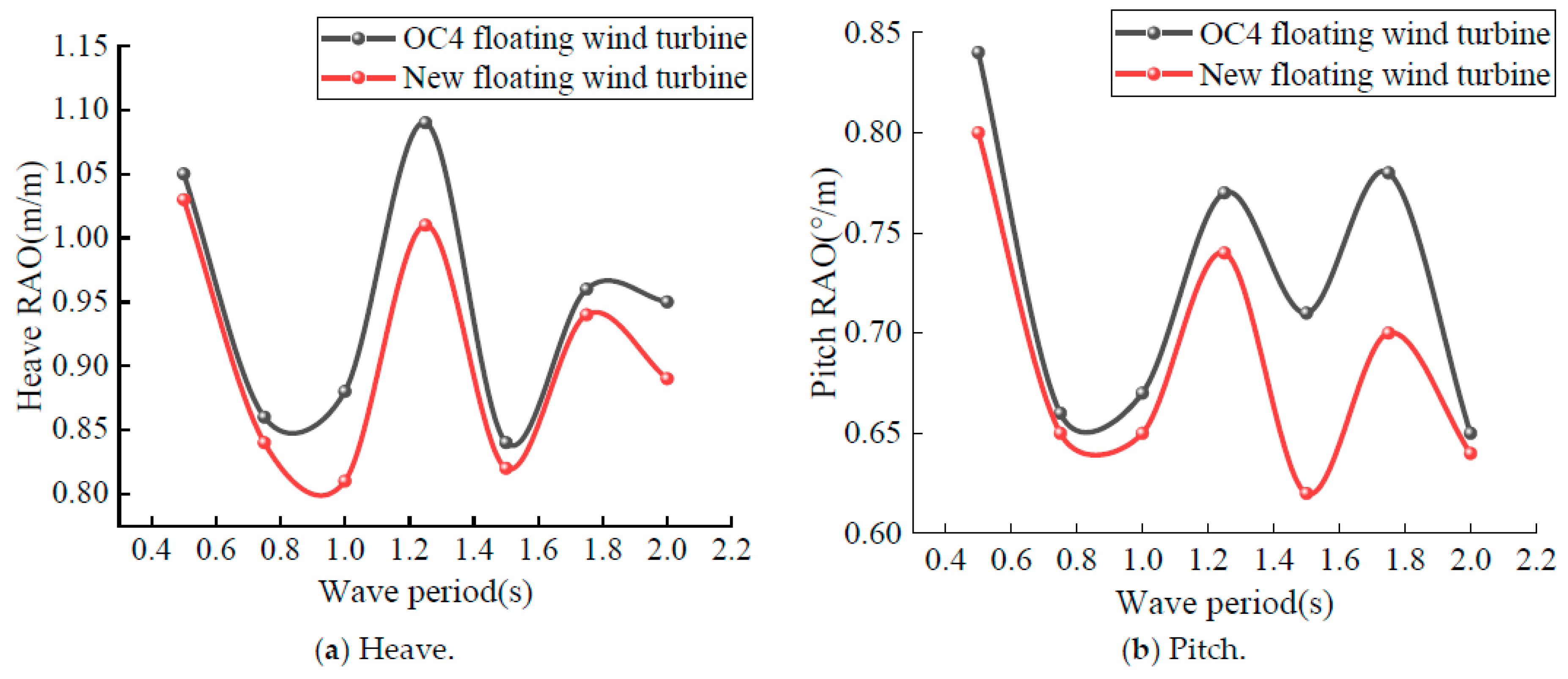
The proposed floating platform and the OC4-DeepCwind platform serve as the support structures for the OFWT during the test, respectively. The movements of the OFWT in all six DOFs under different external load conditions were measured using the Qualisys motion capture system. Given that the turbine’s movements in the heave and pitch directions profoundly influence its safety and power generation efficiency, the test results in these two directions under various external load conditions are shown in Figure 13 and Figure 14.
It is worth noting that, to minimize the influence of size on the evaluation results, Figure 13 and Figure 14 employed RAOs, which represent the ratios of turbine motion in a specific direction to the amplitude of the waves, thereby describing the seakeeping performance of the OFWT under various external loading conditions. From the results depicted in Figure 13 and Figure 14, when compared to the OC4 floating offshore wind turbine, it is obvious to see that the novel floating offshore wind turbine shows favorable heave and pitch motion performance in different wave periods, both under pure wave loading and combined loading conditions with varying wave periods and steady winds.
6. Conclusions
A novel floating wind turbine foundation has been proposed based on the OC4-DeepCwind floating foundation. Models of the systems were created and frequency–domain response analyses were conducted using Ansys AQWA, along with wind–wave experiments. The research findings lead to the following conclusions.
- Introducing viscous damping enables a more accurate determination of the corresponding natural period’s RAO, thus providing a more realistic reflection of the hydrodynamic characteristics of floating wind turbines. This enhances the reliability of the simulation comparisons between the two semi-submersible wind turbine platforms. The results indicate a lower RAO for the new floating wind turbine platform.
- The comparative frequency–domain analysis between the new design of the semi-submersible floating wind turbine and the OC4-DeepCwind platform revealed that a smaller diameter float contacting the water surface resulted in a better motion performance. However, the interaction between the floater and the water surface changes as the platform moves. Therefore, the next step could involve altering the height of the floater’s small waterline area and conducting fully coupled simulation experiments for the better optimization of the new design of the semi-submersible floating platform’s structure and performance.
- In scale model experiments under wind–wave conditions, the comparative analysis between the experimental and numerical simulations revealed the significant impact of steady wind waves on OFWTs at different wave periods. Compared to the OC4-DeepCwind platform, the new floating offshore wind turbine could better avoid energy concentration areas and low-frequency wave ranges, thereby preventing platform resonance and improving motion stability.
- The reduced diameter of the float at the waterline in the new design of the semi-submersible floating wind turbine could lower manufacturing costs as compared to the OC4-DeepCwind platform. However, the extent of diameter reduction must be considered in conjunction with overall strength. Future work will involve comprehensive strength testing of the new design of the semi-submersible floating platform.
Author Contributions
Methodology, X.W.; Software, X.W.; Formal analysis, Z.Z.; Data curation, H.Z. and Z.Z.; Writing—original draft, H.Z.; Writing—review & editing, Z.Z. All authors have read and agreed to the published version of the manuscript.
Funding
The work was supported by the Hunan Natural Science Foundation (Grant Nos. 2024JJ7110 and 2021JJ50105), the Xiangtan Science and Technology Plan Project (Grant Nos. ZX-YB20231004), and the Postgraduate Scientific Research Innovation Project of Hunan Province (CX20231280).
Data Availability Statement
The original contributions presented in the study are included in the article, further inquiries can be directed to the corresponding author.
Conflicts of Interest
The authors declare no conflict of interest.
References
- Edwards, E.C.; Holcombe, A.; Brown, S.; Ransley, E.; Hann, M.; Greaves, D. Trends in floating offshore wind platforms: A review of early-stage devices. Renew. Sustain. Energy Rev. 2024, 193, 114271. [Google Scholar] [CrossRef]
- Zhou, B.; Zhang, Z.; Li, G.; Yang, D.; Santos, M. Review of key technologies for offshore floating wind power generation. Energies 2023, 16, 710. [Google Scholar] [CrossRef]
- Lemmer, F.; Yu, W.; Müller, K.; Cheng, P.W. Semi-submersible wind turbine hull shape design for a favorable system response behavior. Mar. Struct. 2020, 71, 102725. [Google Scholar] [CrossRef]
- Zhang, H.; Wang, H.; Cai, X.; Xie, J.; Wang, Y.; Zhang, N. Novel method for designing and optimising the floating platforms of offshore wind turbines. Ocean Eng. 2022, 266, 112781. [Google Scholar] [CrossRef]
- Liu, Z.; Zhou, Q.; Tu, Y.; Wang, W.; Hua, X. Proposal of a novel semi-submersible floating wind turbine platform composed of inclined columns and multi-segmented mooring lines. Energies 2019, 12, 1809. [Google Scholar] [CrossRef]
- Scicluna, D.; De Marco Muscat-Fenech, C.; Sant, T.; Vernengo, G.; Tezdogan, T. Preliminary analysis on the hydrostatic stability of a self-aligning floating offshore wind turbine. J. Mar. Sci. Eng. 2022, 10, 2017. [Google Scholar] [CrossRef]
- Rezanejad, K.; Gadelho, J.F.M.; Xu, S.; Soares, C.G. Experimental investigation on the hydrodynamic performance of a new type floating Oscillating Water Column device with dual-chambers. Ocean Eng. 2021, 234, 109307. [Google Scholar] [CrossRef]
- Cheng, P.; Huang, Y.; Wan, D. A numerical model for fully coupled aero-hydrodynamic analysis of floating offshore wind turbine. Ocean Eng. 2019, 173, 183–196. [Google Scholar] [CrossRef]
- Tabeshpour, M.R.; Hajnoruzi, F. Conceptual study on dynamic responses of semi-submersible platforms. In Proceedings of the Institution of Civil Engineers-Maritime Engineering; Thomas Telford Ltd.: London, UK, 2023; Volume 176, pp. 31–43. [Google Scholar]
- Yang, Y.; Bashir, M.; Michailides, C.; Li, C.; Wang, J. Development and application of an aero-hydro-servo-elastic coupling framework for analysis of floating offshore wind turbines. Renew. Energy 2020, 161, 606–625. [Google Scholar] [CrossRef]
- Gao, J.L.; Lyu, J.; Wang, J.H.; Zhang, J.; Liu, Q.; Zang, J.; Zou, T. Study on transient gap resonance with consideration of the motion of floating body. China Ocean Eng. 2022, 36, 994–1006. [Google Scholar] [CrossRef]
- Gao, J.L.; Lyu, J.; Zhang, J.; Zang, J. Influences of floater motion on gap resonance triggered by focused wave groups. China Ocean Eng. 2023, 37, 685–697. [Google Scholar] [CrossRef]
- Gong, S.K.; Gao, J.L.; Mao, H.F. Investigations on fluid resonance within a narrow gap formed by two fixed bodies with varying breadth ratios. China Ocean Eng. 2023, 37, 962–974. [Google Scholar] [CrossRef]
- Zou, Q.; Lu, Z.; Shen, Y. Short-term prediction of hydrodynamic response of a novel semi-submersible FOWT platform under wind, current and wave loads. Ocean Eng. 2023, 27, 114471. [Google Scholar] [CrossRef]
- Bashetty, S.; Ozcelik, S. Review on dynamics of offshore floating wind turbine platforms. Energies 2021, 14, 6026. [Google Scholar] [CrossRef]
- Deng, Y.; Feng, W.; Xu, S.; Chen, X.; Wang, B. A novel approach for motion predictions of a semi-submersible platform with neural network. J. Mar. Sci. Technol. 2020, 26, 883–895. [Google Scholar] [CrossRef]
- Zhang, Y.; Xu, H.; Law, Y.; Santo, H.; Magee, A. Hydrodynamic analysis and validation of the floating DeepCwind semi-submersible under 3-h irregular wave with the HOS and CFD coupling method. Ocean Eng. 2023, 287, 115701. [Google Scholar] [CrossRef]
- Falnes, J.; Kurniawan, A. Ocean Waves and Oscillating Systems: Linear Interactions Including Wave-Energy Extraction; Cambridge University Press: Cambridge, UK, 2020. [Google Scholar]
- Robertson, A.; Jonkman, J.; Masciola, M.; Song, H.; Goupee, A.; Coulling, A.; Luan, C. Definition of the Semi-Submersible Floating System for Phase II of OC4; National Renewable Energy Lab.(NREL): Golden, CO, USA, 2014.
- Choi, Y.R.; Hong, S.Y.; Choi, H.S. An analysis of second-order wave forces on floating bodies by using a higher-order boundary element method. Ocean Eng. 2001, 28, 117–138. [Google Scholar] [CrossRef]
- Tran, T.T.; Kim, D.H. The coupled dynamic response computation for a semi-submersible platform of floating offshore wind turbine. J. Wind Eng. Ind. Aerodyn. 2015, 147, 104–119. [Google Scholar] [CrossRef]
- Liu, Z.; He, J.; Meng, Y.; Zhang, H.; Zhou, Y.; Tao, L. Numerical and experimental study on the influence of a moonpool on motion performance and stability of a drillship. Ocean Eng. 2022, 262, 112241. [Google Scholar] [CrossRef]
- Lopez-Pavon, C.; Souto-Iglesias, A. Hydrodynamic coefficients and pressure loads on heave plates for semi-submersible floating offshore wind turbines: A comparative analysis using large scale models. Renew. Energy 2015, 81, 864–881. [Google Scholar] [CrossRef]
- Joseph, D.D. Potential flow of viscous fluids: Historical notes. Int. J. Multiph. Flow 2006, 32, 285–310. [Google Scholar] [CrossRef]
- Felder, S.; Chanson, H. Turbulence, dynamic similarity and scale effects in high-velocity free-surface flows above a stepped chute. Exp. Fluids 2009, 47, 1–18. [Google Scholar] [CrossRef]
Figure 1.
Flowchart of research approach and methodology.

Figure 2.
The OC4-DeepCwind platform and the proposed platform.
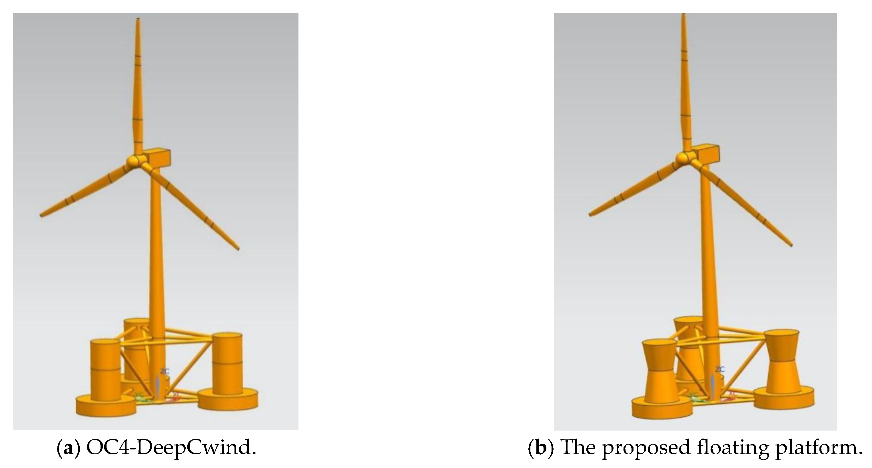
Figure 3.
Schematic diagram of the two floating platforms.

Figure 4.
The schematic diagram of the mooring system.
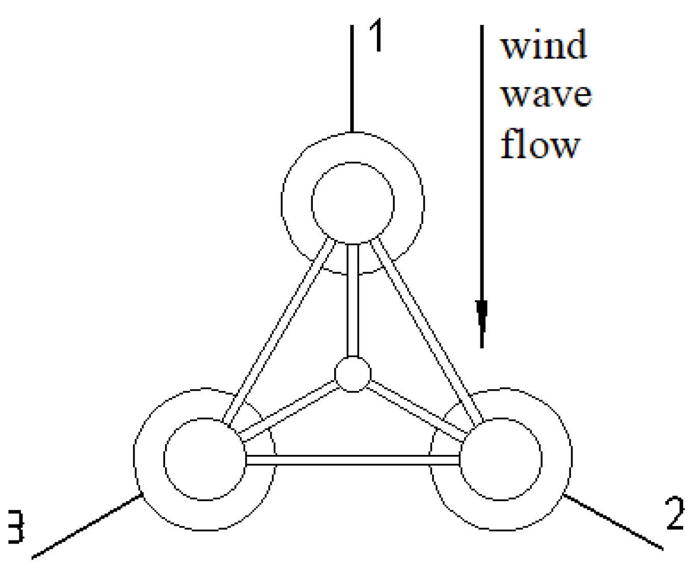
Figure 5.
Meshing results of the two types of floating platforms.
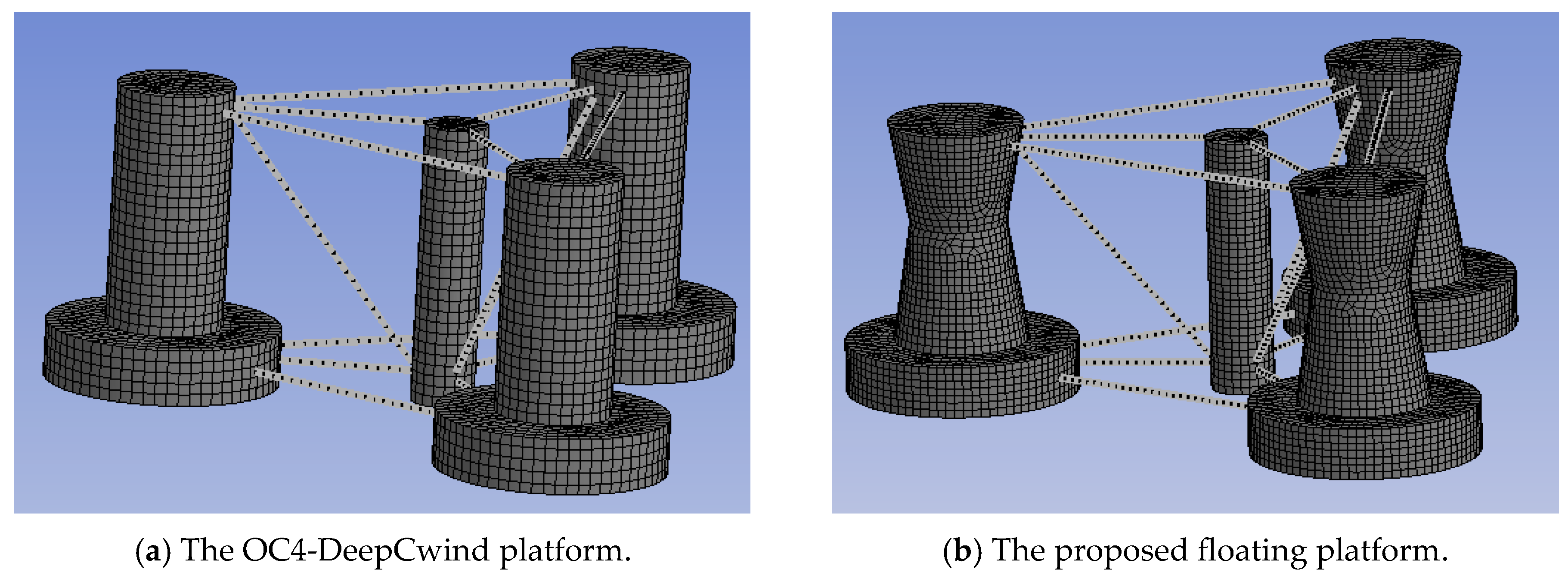
Figure 6.
Second-order mean drift forces in the surge direction.
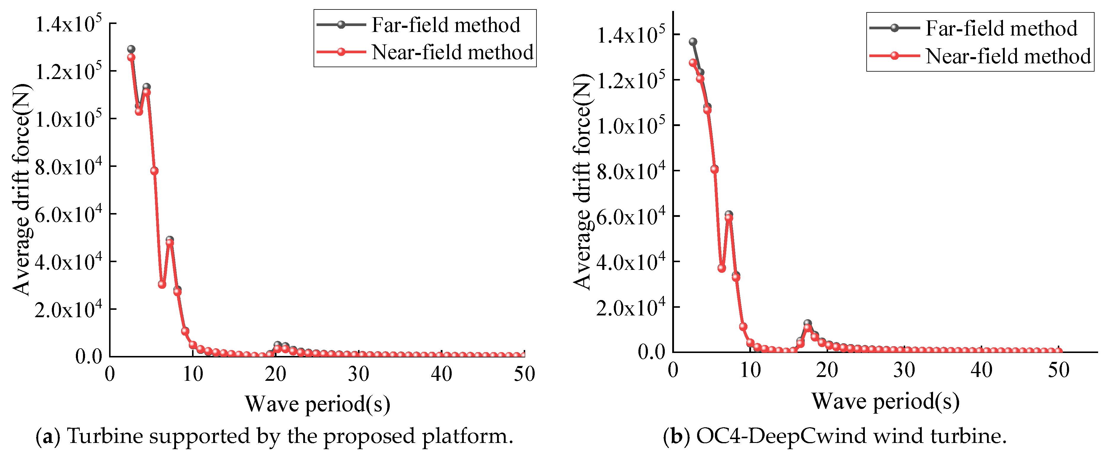
Figure 7.
RAOs of the OFWT were obtained before and after considering additional viscous damping.
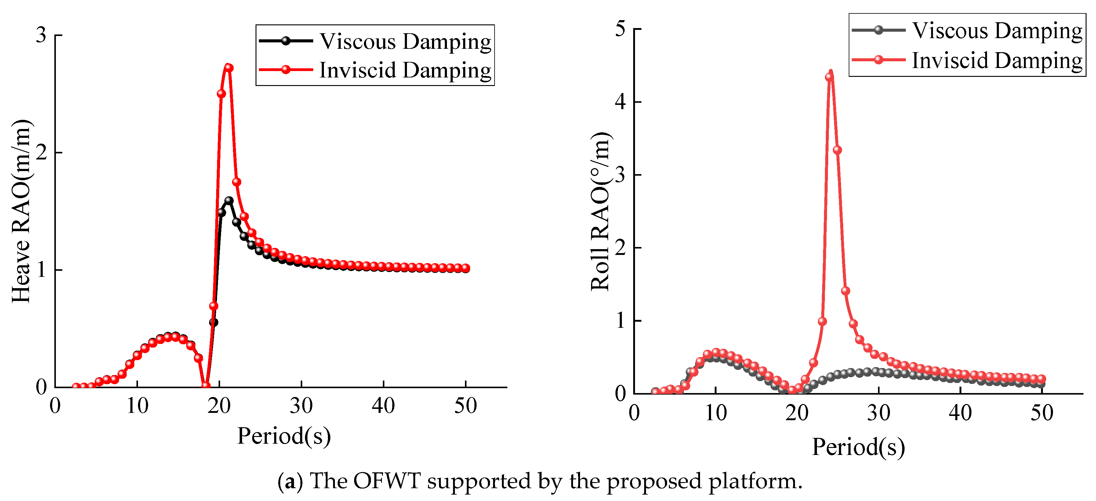

Figure 8.
RAOs of the OFWT when supported by the proposed floating platform.


Figure 9.
Comparison of the RAOs when the OFWT is supported by the two types of platform.
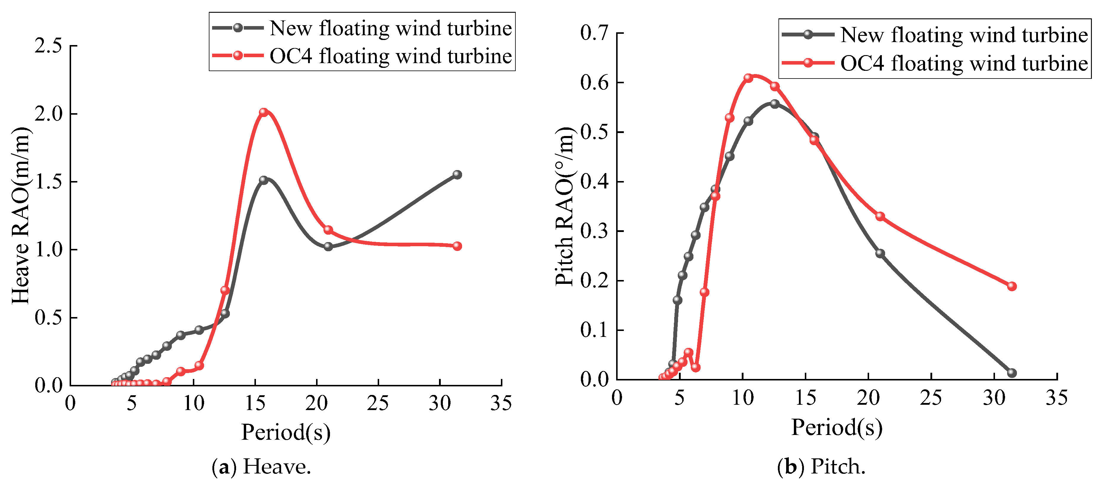
Figure 10.
Water tank used for the model tests.
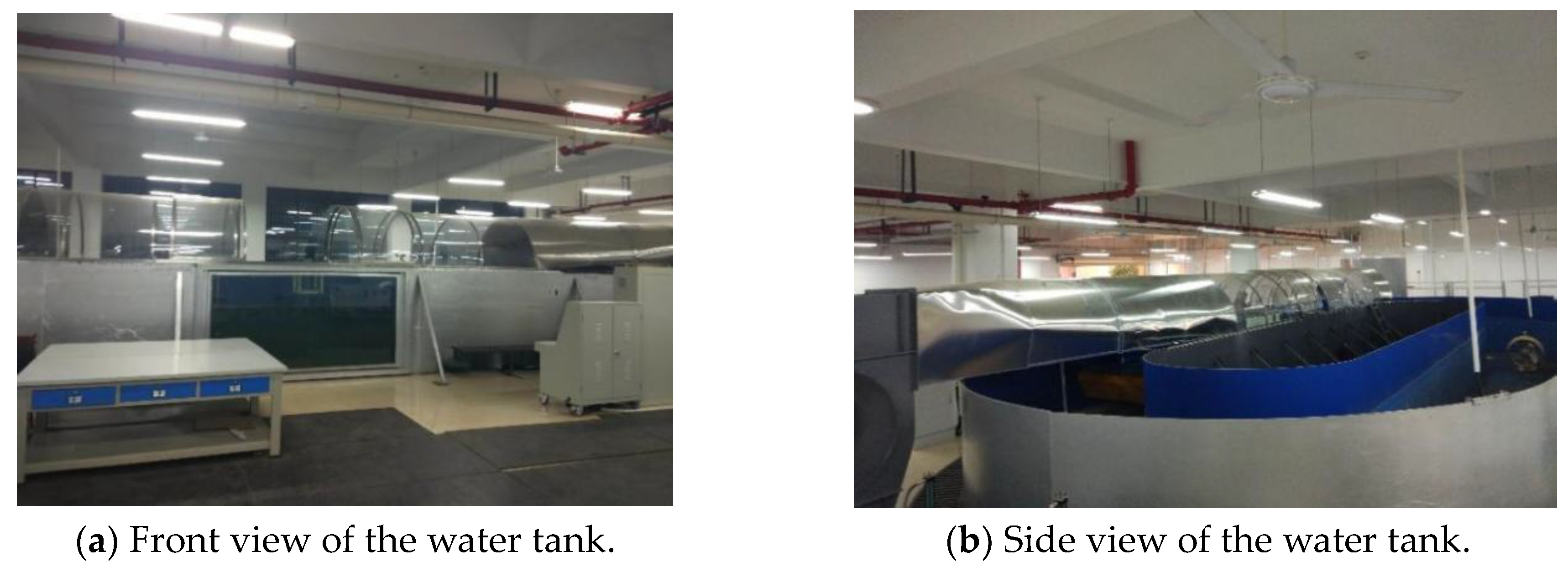
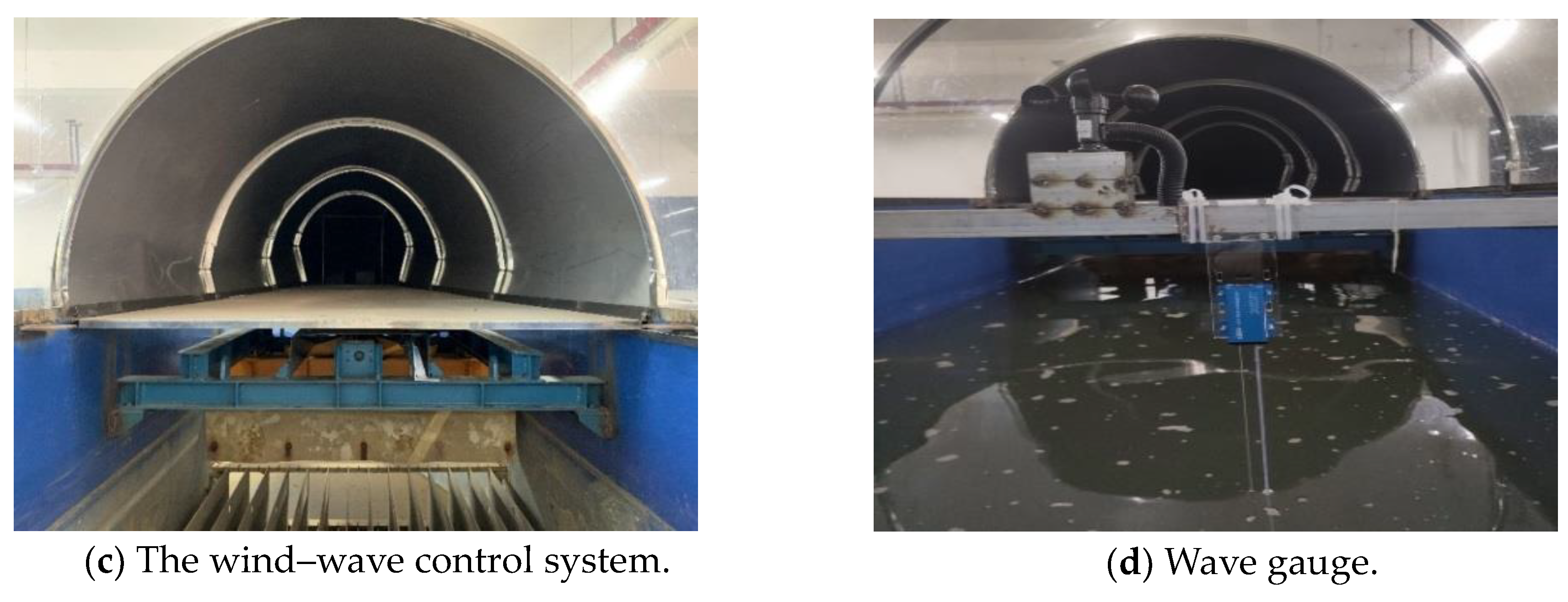
Figure 11.
Qualisys motion capture system.
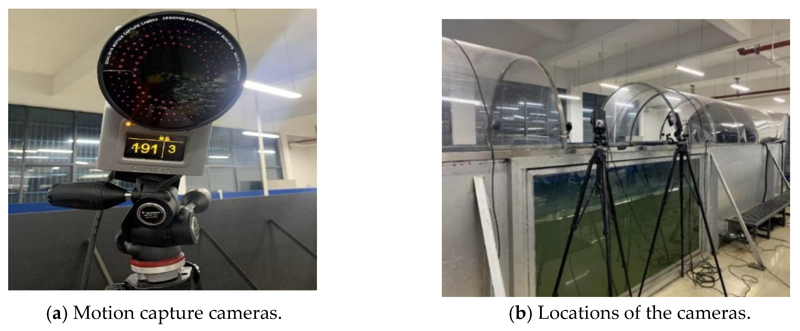
Figure 12.
The scaled models of the OFWT.
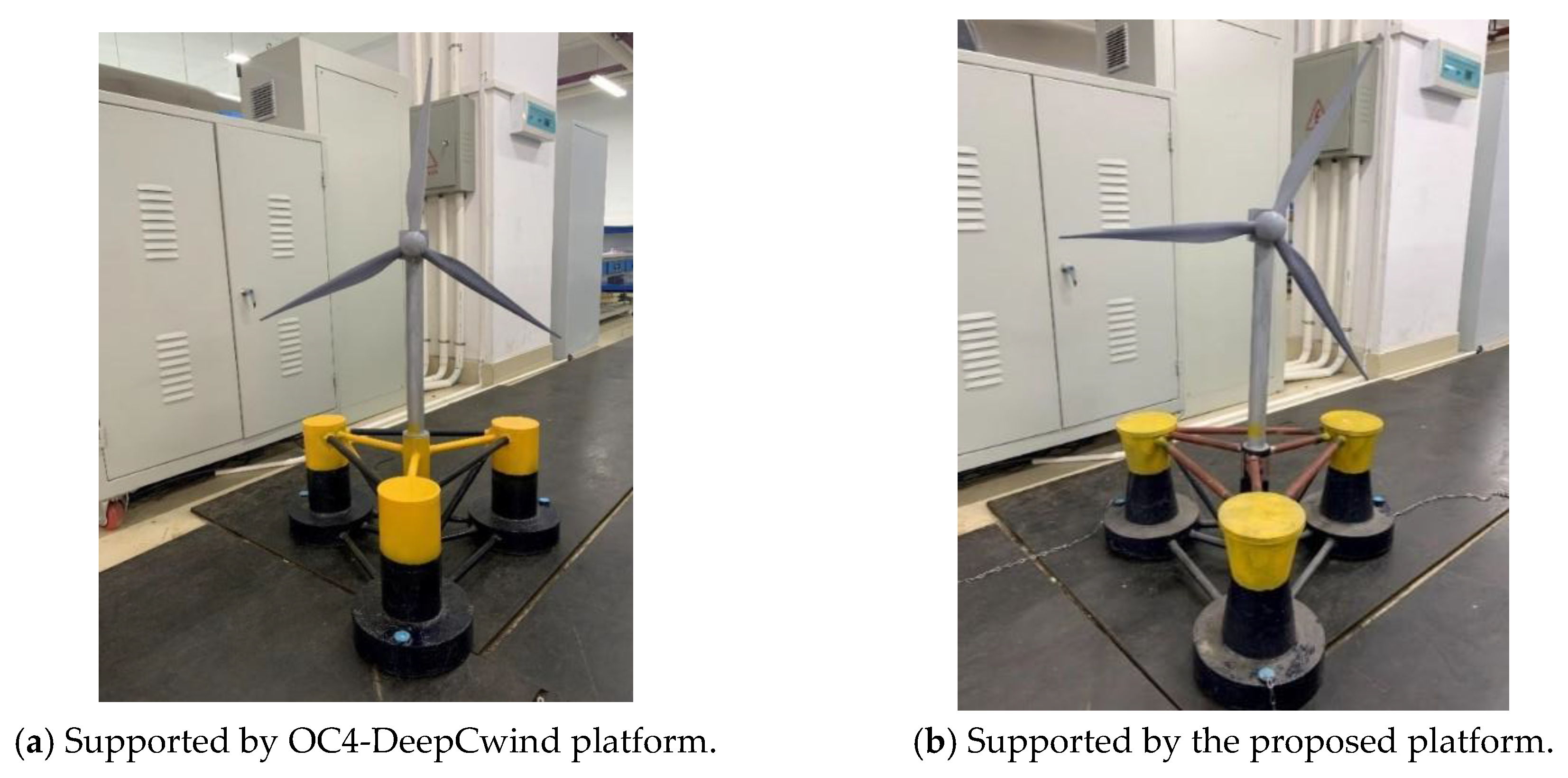
Figure 13.
Test results were obtained under pure wave excitation.
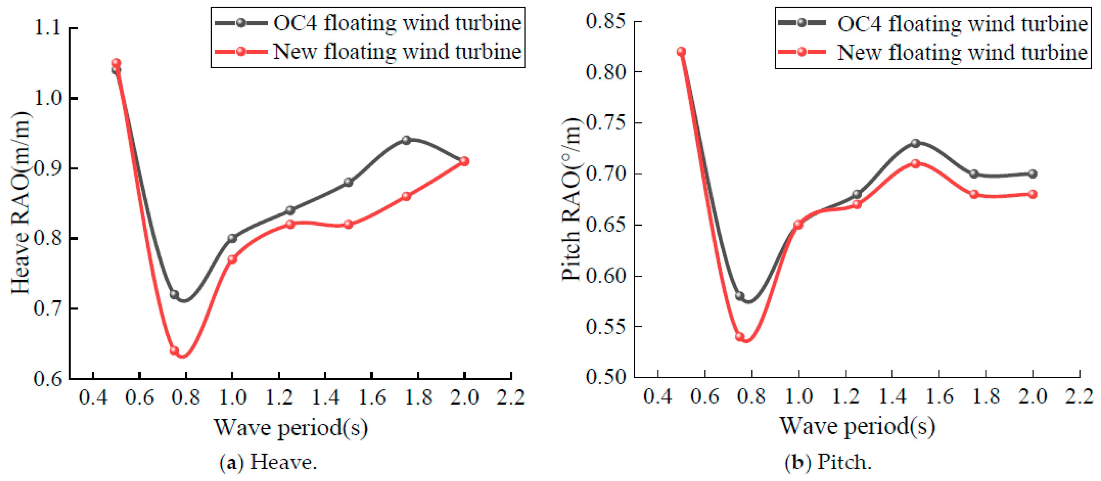
Figure 14.
Test results obtained under wind–wave combined excitation.

Table 1.
Detailed design parameters of the floating platforms.
| Parameters | Proposed Floating Platform | OC4-DeepCwind Platform |
|---|---|---|
| Draft (m) | 20 | 20 |
| Height above waterline of floater (m) | 12 | 12 |
| Outer bottom floater diameter (m) | 24 | 24 |
| Diameter at the outer draft line (m) | 10 | 12 |
| Diameter of outer floater (m) | 12 | 12 |
| Diameter of lower conical floater (m) | 12 | 12 |
| Height of lower conical float below Waterline (m) | 14 | 14 |
| Height of upper conical floater above Waterline (m) | 12 | 12 |
| Distance between outer-side pontoons (m) | 50 | 50 |
| Diameter of central pontoon (m) | 6 | 6 |
| Height of central pontoon (m) | 30 | 30 |
| Diameter of support column (m) | 1.6 | 1.6 |
| Total mass (kg) | 1.335 × 10⁷ | 1.347 × 10⁷ |
| Moment of inertia Ixx (kg/m2) | 7.370 × 10⁹ | 6.827 × 10⁹ |
| Moment of inertia Iyy (kg/m2) | 7.371 × 10⁹ | 6.827 × 10⁹ |
| Moment of inertia Izz (kg/m2) | 1.114 × 10¹⁰ | 1.226 × 10¹⁰ |
Table 2.
Mooring chain parameters.
| Parameters | Numerical Value |
|---|---|
| Quantity | 3 |
| Length (m) | 507 |
| Mass per unit length (kg/m) | 150 |
| Equivalent interfacial area (m2) | 0.01 |
| Axial stiffness (N/m) | 753,600,000 |
| Breaking force (N) | 6,090,000 |
| Added mass coefficient | 1.1 |
| Drag coefficient | 1.0 |
| Axial drag coefficient | 0.1 |
| Longitudinal damping coefficient | 0.025 |
Table 3.
Additional viscous damping of the OFWT.
| Platform | DOFs | Inertial Mass/kg | Added Mass/kg | Restoring Stiffness/N × m−1 | Critical Damping /N × (m/s)−1 or /N × m × (°/s)−1 | Viscous Damping /N × (m/s)−1 or /N × m × (°/s)−1 |
|---|---|---|---|---|---|---|
| Proposed platform | Heave | 1.33 × 10⁷ | 1.44 × 10⁷ | 2.75 × 10⁸ | 1.75 × 10⁶ | 8.74 × 10⁵ |
| Roll | 7.37 × 10⁹ | 1.08 × 10⁸ | 1.67 × 10⁷ | 7.07 × 10⁸ | 3.53 × 10⁷ | |
| Pitch | 7.37 × 10⁹ | 1.08 × 10⁸ | 1.67 × 10⁷ | 7.07 × 10⁸ | 3.53 × 10⁷ | |
| OC4-Deep Cwind | Heave | 1.34 × 10⁷ | 1.42 × 10⁷ | 3.79 × 10⁶ | 2.05 × 10⁷ | 1.02 × 10⁶ |
| Roll | 6.82 × 10⁹ | 1.08 × 10⁸ | 2.55 × 10⁷ | 8.42 × 10⁸ | 4.21 × 10⁷ | |
| Pitch | 6.82 × 10⁹ | 1.08 × 10⁸ | 2.55 × 10⁷ | 8.42 × 10⁸ | 4.21 × 10⁷ |
Table 4.
Matrix of testing conditions.
| Loading Conditions | Wave Period (s) | Wave Height (m) | Wind Speed (m/s) |
|---|---|---|---|
| Pure wave | 0.50 | 0.05 | --- |
| 0.75 | 0.05 | --- | |
| 1.00 | 0.05 | --- | |
| 1.25 | 0.05 | --- | |
| 1.50 | 0.05 | --- | |
| 1.75 | 0.05 | --- | |
| 2.00 | 0.05 | ||
| Wind–wave combined | 0.50 | 0.05 | 6.0 |
| 0.75 | 0.05 | 6.0 | |
| 1.00 | 0.05 | 6.0 | |
| 1.25 | 0.05 | 6.0 | |
| 1.50 | 0.05 | 6.0 | |
| 1.75 | 0.05 | 6.0 | |
| 2.00 | 0.05 | 6.0 |
Disclaimer/Publisher’s Note: The statements, opinions and data contained in all publications are solely those of the individual author(s) and contributor(s) and not of MDPI and/or the editor(s). MDPI and/or the editor(s) disclaim responsibility for any injury to people or property resulting from any ideas, methods, instructions or products referred to in the content. |
© 2024 by the authors. Licensee MDPI, Basel, Switzerland. This article is an open access article distributed under the terms and conditions of the Creative Commons Attribution (CC BY) license (https://creativecommons.org/licenses/by/4.0/).
Share and Cite
MDPI and ACS Style
Zhao, H.; Wu, X.; Zhou, Z. Exploring Motion Stability of a Novel Semi-Submersible Platform for Offshore Wind Turbines. Energies 2024, 17, 2313. https://doi.org/10.3390/en17102313
AMA Style
Zhao H, Wu X, Zhou Z. Exploring Motion Stability of a Novel Semi-Submersible Platform for Offshore Wind Turbines. Energies. 2024; 17(10):2313. https://doi.org/10.3390/en17102313
Chicago/Turabian StyleZhao, Hongxu, Xiang Wu, and Zhou Zhou. 2024. "Exploring Motion Stability of a Novel Semi-Submersible Platform for Offshore Wind Turbines" Energies 17, no. 10: 2313. https://doi.org/10.3390/en17102313
Note that from the first issue of 2016, this journal uses article numbers instead of page numbers. See further details here.